

Page 1

PROPRIETARY INFORMATION
ALL RIGHTS RESERVD, NO PARTS OF THIS DOCUMENT MAY BE REPRODUCED, STORD IN
RETRIEVAL SYSTEM, OR TRANSMITTED IN ANY FORM OR BY ANY MEANS, ELECTRONIC,
MECHANICAL PHOTOCOPYING, RECORDING OR OTHERWISE WITHOUT THE PRIOR WRITTEN
PERMISSION OF TELEMATICS WIRELESS LTD. NOR USED IN WHOLE OR IN PART FOR ANY
PURPOSE OR FOR ANY CUSTOMER EXCEPT TELEMATICS WIRELESS.
NAME:
FP310RAM-X
User Manual
DESIGNED
M.N.
March 2009
SHEET/OF
CHECKED
G.F.K
March 2009
1
21
APPROVED
A.S.
March 2009
Q.A.
A.S.
March 2009
PROD/PROJ: FP310RAM-X ASTM Mini Reader
SIZE
2 1 4 0 7 2 0 4 6 0 0
0
REV.
DESCRIPTION
E.C.N.
DATE
DRAWN
CHECKED
A
Page 2

PROPRIETARY
Note:
This device complies with Part 15 of the FCC Rules.
Operation is subject to the following two conditions:
1) This device may not cause harmful interference, and
2) This device must accept any interference received, including interference that may
cause undesired operation.
WARNING! Changes or modifications to this unit not expressly approved by Telematics
Wireless Ltd. could void the user's authority to operate the equipment.
The digital portion of the transceiver has been tested and found to comply with the limits for a
Class B digital device, pursuant to part 15 of the FCC Rules. These limits are designed to provide
reasonable protection against harmful interference in a residential installation. This equipment
generates uses and can radiate radio frequency energy and, if not installed and used in accordance
with the instructions, may cause harmful interference to radio communications. However, there is
no guarantee that interference will not occur in a particular installation. If this equipment does
cause harmful interference to radio or television reception, which can be determined by turning
the equipment off and on, the user is encouraged to try to correct the interference by the
following measure:
-Increase the separation between the equipment and receiver.
The antenna and therefore the unit, used for this transmitter must be installed to normally provide
minimum separation distance of at least 2 meters from all persons and must not be co-located or
operating in conjunction with any other antenna or transmitter.
Page 3

Table of Contents
PROPRIETARY
ii
This document contains proprietary information, which is the sole
property of Telematics-Wireless. The document is submitted to the
recipient for his use only. By receiving this document the recipient
undertakes not to duplicate or to disclose in part of, or the whole of, any
of the information contained herein to any third party without receiving
before hand, written permission from the submitting company.
FP310RAM-X
Mini Reader
User Manual
Version 1.1
Telematics Wireless Ltd.
26 Hamelacha St., POB 1911
Holon, 58117
Israel
Phone: +(972)3-5575717
Fax: +(972)3-5575713 March 2010
Page 4

Table of Contents
PROPRIETARY
iii
Table of Contents
Chapter 1 ...................................................................................................................... 1-1-2
Introduction .................................................................................................................. 1-1-2
1-1. Scope ............................................................................................................. 1-1-2
1-2. General Description ....................................................................................... 1-1-3
1-2.1 Purpose and Use ............................................................................... 1-1-3
1-2.2 Main Technical Characteristics ........................................................ 1-1-3
1-2.3 Host Utility ....................................................................................... 1-1-3
1-2.4 Additional Equipment Needed .......................................................... 1-1-3
1-2.5 FP310RAM-X vs. FP300RA ............................................................ 1-1-4
1-3. Physical Description ...................................................................................... 1-1-4
1-4. Functional Description .................................................................................. 1-1-5
1-4.1 Normal Mode .................................................................................... 1-1-5
1-4.2 Mute Mode ........................................................................................ 1-1-5
1-4.3 Maintenance Mode ........................................................................... 1-1-5
1-4.4 Host Communication ........................................................................ 1-1-5
Chapter 2 ...................................................................................................................... 2-2-1
Installation ................................................................................................................... 2-2-1
2-1. General........................................................................................................... 2-2-1
2-2. Installation Requirements .............................................................................. 2-2-1
2-2.1 Integration in Systems ...................................................................... 2-2-1
2-2.2 Safety Considerations ....................................................................... 2-2-1
2-2.3 Mechanical Data ............................................................................... 2-2-2
2-3. Installation Guidelines ................................................................................... 2-2-2
2-3.1 Power Requirements ......................................................................... 2-2-2
2-3.2 Antenna ............................................................................................. 2-2-2
2-3.3 Communication Cables ..................................................................... 2-2-3
2-3.4 Grounding and Lightning Protection Requirements ......................... 2-2-3
2-4. Installation Procedure .................................................................................... 2-2-3
2-4.1 Tools and Materials .......................................................................... 2-2-3
2-4.2 Preparation for Installation ............................................................... 2-2-3
2-4.3 FP310RAM-X Installation Procedure .............................................. 2-2-4
Chapter 3 ...................................................................................................................... 3-3-1
Operation ..................................................................................................................... 3-3-1
3-1. Scope ............................................................................................................. 3-3-1
3-2. Power-Up ....................................................................................................... 3-3-1
Appendix A .................................................................................................................. A-1
Page
Connection Data .......................................................................................................... A-1
A-1. Antenna Connector .......................................................................................... A-1
A-2. Power Input Connector .................................................................................... A-1
A-3. Host Interface Connector ................................................................................. A-1
A-4. I/O Connector .................................................................................................. A-1
Page 5

Table of Contents
PROPRIETARY
iv
List of Illustrations
Figure 1-1. FP310RAM-X, General View ....................................................................................... 1-1-3
Figure 1-2. FP310RAM-X, Host Side Panel .................................................................................... 1-1-4
Figure 1-3. FP310RAM-X, Antenna Side Panel .............................................................................. 1-1-4
Figure 2-1. FP-310RA Connections ................................................................................................. 2-2-1
Figure 2-2. FP310RAM-X Mechanical Data ................................................................................... 2-2-2
List of Tables
Table 1-1. FP-310RA Connectors, Indicators and Controls ............................................................. 1-1-5
Table A-1. DC IN Connector, Pin Functions ...................................................................................... A-1
Table A-2. HOST Connector, Pin Functions for RS-232 Interface ..................................................... A-1
Table A-3. I/O Connector .................................................................................................................... A-1
Page 6

PROPRIETARY
1-1
Chapter 1
INTRODUCTION
Contents
1-1. Scope ................................................................ ............................................. 1-1-2
1-2. General Description ....................................................................................... 1-1-3
1-2.1 Purpose and Use ............................................................................... 1-1-3
1-2.2 Main Technical Characteristics ........................................................ 1-1-3
1-2.3 Host Utility ....................................................................................... 1-1-3
1-2.4 Additional Equipment Needed .......................................................... 1-1-3
1-2.5 FP310RAM-X vs. FP300RA ............................................................ 1-1-4
1-3. Physical Description ...................................................................................... 1-1-4
1-4. Functional Description .................................................................................. 1-1-5
1-4.1 Normal Mode .................................................................................... 1-1-5
1-4.2 Mute Mode ........................................................................................ 1-1-5
1-4.3 Maintenance Mode ........................................................................... 1-1-5
1-4.4 Host Communication ........................................................................ 1-1-5
Page 7

Scope
PROPRIETARY
1-2
Presents the manual scope and organization, and describes the
FP310RAM-X mini reader functions and capabilities.
Chapter 1 – Introduction
Provides the information needed to plan the FP310RAM-X installation,
and detailed installation instructions.
Chapter 2 – Installation
Provides information on the FP310RAM-X operating modes.
Chapter 3 – Operation
Presents the information needed to connect to the FP310RAM-X.
Appendix A –
Connection Data
Chapter 1
Introduction
1-1. Scope
This manual covers the characteristics, applications, installation, configuration and maintenance of the
FP310RAM-X mini reader, an advanced and flexible roadside component offered by Telematics Wireless
for use in electronic Automatic Vehicle Identification (AVI) systems.
The information included in this manual is organized as follows:
For additional information on the FP310RAM-X technical specifications, its systems integration, help in
interfacing to the FP310RAM-X, and other issues regarding utilization of FP310RAM-X advanced
characteristics, contact Telematics Wireless.
Page 8
General Description
PROPRIETARY
1-3
1-2. General Description
1-2.1 Purpose and Use
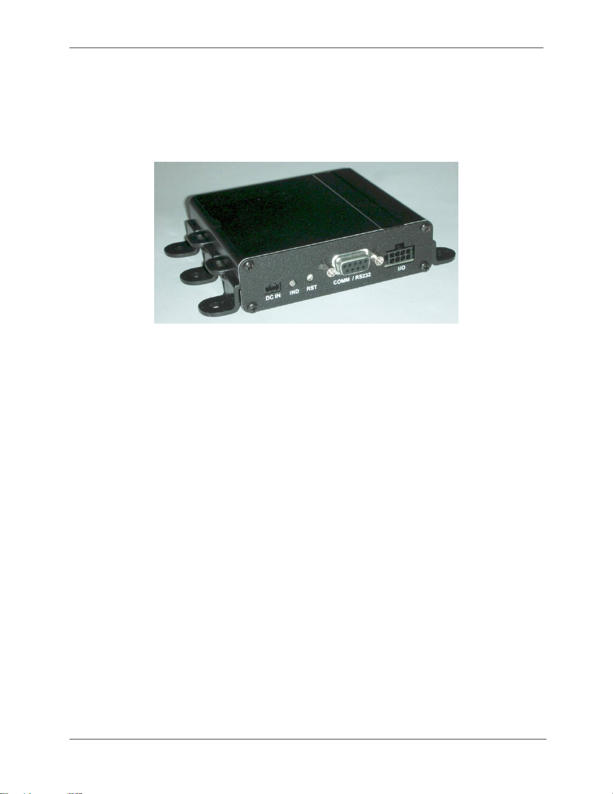
The FP310RAM-X mini reader offered by Telematics Wireless is a versatile, compact and reliable unit
that serves as the reader component of a vehicle identification system. Figure 1-1 shows a general view of
the FP310RAM-X.
Figure 1-1. FP310RAM-X, General View
The Telematics Wireless Mini Reader FP310RAM-X is a reduced version of Telematics Wireless
FP300RA road side reader. The mini reader is a versatile, compact, and reliable unit that serves as an
integral part of a vehicle identification system and may be used to read and write data to and from TDMA
tags and to activates the tag's driver alert signal. The FP310RAM-X mini reader can be used for traffic
load monitoring, gate pass applications, tag testing at point of sale and service and more.
The FP310RAM-X may be operated from DC sources in the range of 9 to 30 VDC. It has low power drain
(less than 0.3 W) and very compact size.
1-2.2 Main Technical Characteristics
The FP310RAM-X supports two-way communications with in-vehicle transponders (“tags”) using the
ASTM V6 Slotted-Aloha Time Division Multiple Access (TDMA) protocol. The physical layer is
compatible with ASTM PS111-98.
The FP310RAM-X communicates with transponders that enter its communication zone at speeds of up to
125 mph (200 kph). The communication uses fixed transmit and receive frequency within the ISM band is
used (915 MHz); the data rate is 500 kbps, with ASK modulation. The FP310RAM-X can use many types
of antennas, to match the spatial resolution needed in the desired operation mode.
1-2.3 Host Utility
Telematics Wireless offers a dedicated reader host utility for the FP310RAM-X that can be installed on
any PC running Microsoft® Corp. Windows 2000 or XP. The FP310RAM-X connects to one of the free
serial communication ports of the PC using a straight modem cable (9 pin to 9 pin). The host utility
provides full control over FP310RAM-X.
1-2.4 Additional Equipment Needed
The only additional accessories that have to be provided are:
Antennas of a type suitable for the specific installation requirements, and the required coaxial
cables for connecting to the antennas.
Page 9

Physical Description
PROPRIETARY
1-4
Function
FP-300RA
FP310RAM-X
RF
Support lanes
Up to 4
1
Tx power output
Software controlled
Fixed
Rx sensitivity
Software controlled
Fixed
Protocol
Report tag found
Yes
Yes
Report tag lost
Yes
Yes
Read/Write to tag
Multiple tags simultaneously
Multiple tags simultaneously
Agency programming
Yes
No
Lists
Active list
128
20
Hot lists
20
None
Tags in hot lists
40,000
None
Auto function
Multi level
None
Interfaces
3 UARTs (Host, Maintenance
and Aux)
1 UART (Host only)
Digital I/O
7 outputs / 8 inputs
2 output / 2 inputs
Input sense
On all inputs
No Real time clock
Yes
No
DC source capable of providing the required supply voltage (9 to 30 VDC) at maximum 0.3 W.
Means for communicating with the host (serial asynchronous communication link).
1-2.5 FP310RAM-X vs. FP300RA
Telematics Wireless FP300RA road side reader became the dominant roadside equipment in the ASTM
CVO market place. The following table summarizes the major differences between the FP300RA and the
FP310RAM-X.
1-3. Physical Description
Figure 1-2 and Figure 1-3 show the components located on the FP310RAM-X (see Figure 1-1 for
orientation). The functions of the various components are described in Table 1-1.
Figure 1-2. FP310RAM-X, Host Side Panel
Figure 1-3. FP310RAM-X, Antenna Side Panel
Page 10

Functional Description
PROPRIETARY
1-5
Side
Item
Function
Host
DC IN Connector
3-pin connector used to connect the DC input voltage.
RESET Push-button
Internal push-button used to initiate cold restart of the FP310RAM-X.
IND Indicator
Status indicator, provides the following indications:
Flashing green: normal operation, no tags detected
Flashing orange: normal operation, tags detected
Flashing red: mute mode (transmission disabled)
Blinking red: Test mode
HOST Connector
9-pin D-type female connector includes a serial asynchronous RS-232
DCE interface used for connection to the host computer.
Antenna
ANT Connector
SMA connector for connection to the main antenna.
I/O
I/O connector
CPA connector
Table 1-1. FP310RAM-X Connectors, Indicators and Controls
1-4. Functional Description
The FP310RAM-X has three operating modes, Normal mode, Mute mode and Maintenance mode.
1-4.1 Normal Mode
The functions performed by the FP310RAM-X during operation in the normal mode are as follows:
Report the transponders that are passing through its communication zone
Maintain a list of the transponders that are currently detected within the reader's
communication zone (active list)
Perform various functions on transponders in response to host requests:
o Read/write transponder internal or external memory
o Operate transponder driver interface
o Send transponder to sleep mode
1-4.2 Mute Mode
In mute mode the reader will not transmit any RF signal.
1-4.3 Maintenance Mode
In maintenance mode the reader can be command to activate various RF test function and to upgrade the
reader's software.
1-4.4 Host Communication
The FP310RAM-X supports communication with a host. Two types of messages are used:
FP310RAM-X initiated message used to report events, e.g., a new transponder
Messages sent in response to host requests.
Page 11

PROPRIETARY
Chapter 2
INSTALLATION
Contents
2-1. General........................................................................................................... 2-2-1
2-2. Installation Requirements .............................................................................. 2-2-1
2-2.1 Integration in Systems ...................................................................... 2-2-1
2-2.2 Safety Considerations ....................................................................... 2-2-1
2-2.3 Mechanical Data ............................................................................... 2-2-2
2-3. Installation Guidelines ................................................................................... 2-2-2
2-3.1 Power Requirements ......................................................................... 2-2-2
2-3.2 Antenna ............................................................................................. 2-2-2
2-3.3 Communication Cables ..................................................................... 2-2-3
2-3.4 Grounding and Lightning Protection Requirements ......................... 2-2-3
2-4. Installation Procedure .................................................................................... 2-2-3
2-4.1 Tools and Materials .......................................................................... 2-2-3
2-4.2 Preparation for Installation ............................................................... 2-2-3
2-4.3 FP310RAM-X Installation Procedure .............................................. 2-2-4
Page 12

PROPRIETARY
i/o
To i/o DEVICE
DC IN
HOST
FP-300RAM-X
To Host Computer
(9 - 30V)
Antenna
ANT
Chapter 2
Installation
2-1. General
This Chapter provides the information needed to install FP310RAM-X mini readers.
The information presented in this Chapter is organized as follows:
Installation requirements – Section 2-2.
Installation guidelines – Section 2-3.
Installation procedures – Section 2-4.
Before starting the installation procedures, make sure to review the Safety Information section at the
beginning of this chapter.
2-2. Installation Requirements
2-2.1 Integration in Systems
Figure 2-1 shows the connections needed to integrate an FP310RAM-X unit in a typical electronic vehicle
identification system. Use the information appearing in Chapter 1 and Appendix A that covers the
FP310RAM-X interface characteristics and connection data, to prepare cables in accordance with the
specific requirements of each location.
Figure 2-1. FP-310RA Connections
2-2.2 Safety Considerations
In addition to the electrical connections shown in Figure 2-1, the FP310RAM-X case must be connected to
protective grounding. Protective devices, complying with the applicable international standards and the
national and local regulations, must be used on all the lines connected to the FP310RAM-X, to protect
against lightning discharges and accidental contact with high-voltage lines.
Page 13
Installation Guidelines
2-2
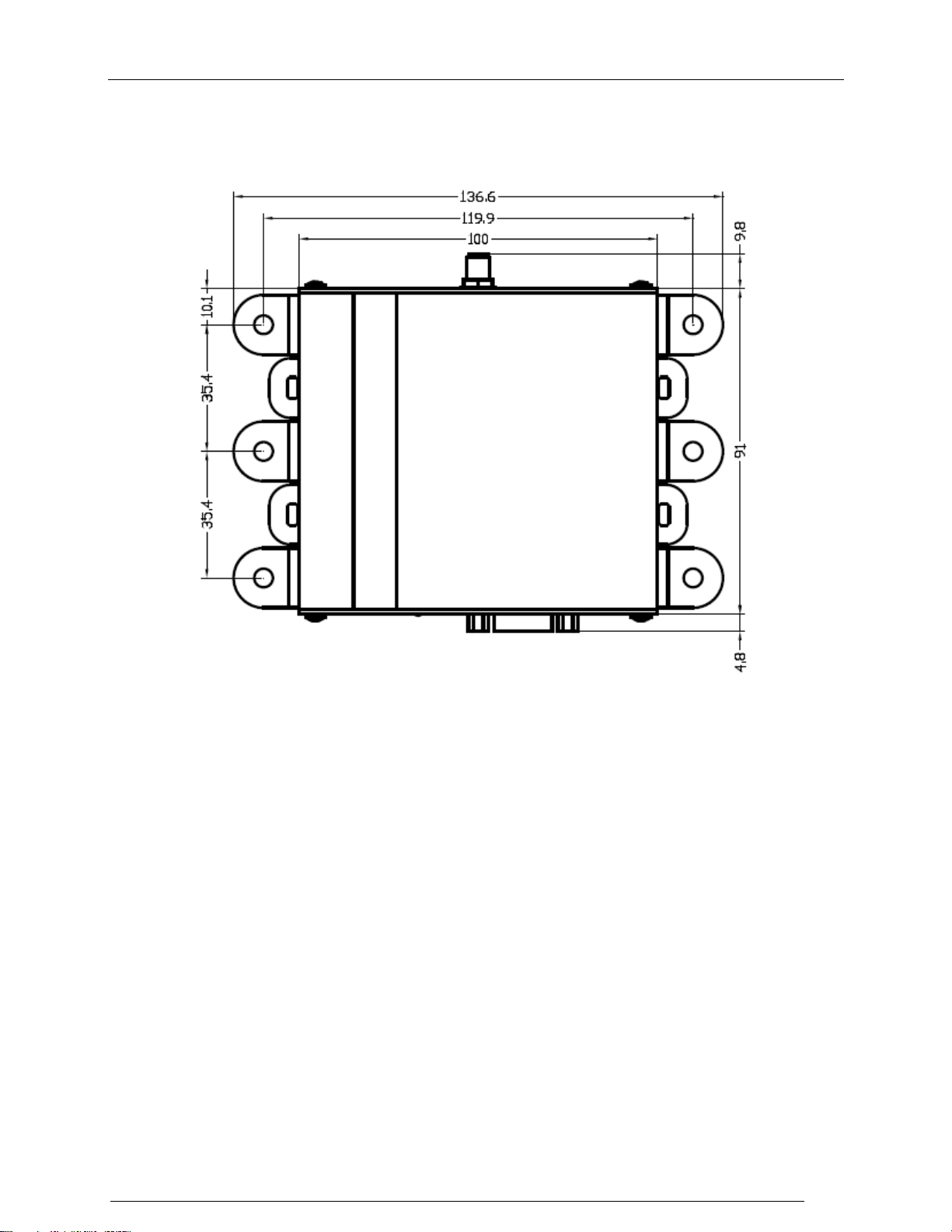
2-2.3 Mechanical Data
Figure 2-2 provides mechanical data for planning the installation of an FP310RAM-X unit.
Figure 2-2. FP310RAM-X Mechanical Data
2-3. Installation Guidelines
The FP310RAM-X is intended for installation in protected cabinets that prevent direct exposure to sun
radiation, rain, dust and dirt. It does not require forced air cooling.
The unit does not have any surge protection units inside.
2-3.1 Power Requirements
The FP310RAM-X operates on 9 to 30 VDC (nominal operation at 12Vdc), at an average power drain of
0.1W with instantaneous peak power of 0.3W. A suitable power source must be provided as part of the
installation.
The FP310RAM-X does not have an ON/OFF power switch, and will start operating as soon as power is
connected. Therefore, it is recommended to install a circuit breaker, which will also serve as an ON/OFF
switch, to protect the supply line of each FP310RAM-X.
2-3.2 Antenna
The type of antenna to be used with the FP310RAM-X is generally determined by the FP310RAM-X
application and communication zone requirements. The positioning of the antenna must be carefully set to
achieve the required communication zone pattern. Contact Telematics Wireless if you need help in
Page 14

Installation Procedure
2-3
Note
The antenna (ANT) connector of the FP310RAM-X must always connected to
antenna or be terminated in matched (50) loads.
selecting suitable antennas.
2-3.2.1 FP310RAM-X-to-Antenna Cabling
The maximum distance between the FP310RAM-X and its antenna is limited by cable signal loss.
Generally, the total signal loss between the antenna and the FP310RAM-X must be less than 3 dB. Any
losses on antenna patch panels must also be taken into consideration.
Cable routes should be carefully planned, to ensure they follow the shortest path yet are far from sources
of strong electrical interference such as electrical motors, air conditioning equipment, two-way radios, etc.
Make sure that cables are physically protected, for example, by routing them within cable ducts: sharp
bends, distortion of the cable outer shield, etc., may increase the attenuation by an unpredictable amount.
2-3.3 Communication Cables
The cables connecting the FP310RAM-X host port must be shielded. Communication-grade cables
consisting of twisted pairs with external shield should be used, and the shield must be grounded at one
end. Cables should be run through grounded conduits, to minimize external interference.
2-3.4 Grounding and Lightning Protection Requirements
All the FP310RAM-Xs, antenna, mounting pole, cabinet, cable conduits and cables must be properly
grounded in accordance with the applicable regulations, to prevent injury to personnel or damage to
equipment from lightning or other high voltage sources.
Ground bonding points must be free of paint and corrosion. Star washers should be placed on screws to
ensure good electrical contact.
For installations where a complete bonded ground connection is not possible for the entire antenna-toFP310RAM-X cabling, a separate lightning arrester must be installed at a point near the RF connection to
the FP310RAM-X cabinet.
2-4. Installation Procedure
2-4.1 Tools and Materials
Huber + Suhner 74Z-0-0-21 - SMA wrench with fixed torque.
Torque screwdriver to close the screws used to mount the FP310RAM-X unit to the cabinet.
2-4.2 Preparation for Installation
Refer to the site installation plan, and make sure all the required components, cables, and accessories are
available.
Identify the prescribed physical location of each system component, and find the grounding points.
Before installing any item (FP310RAM-X, cabinet, mounting accessory, antenna, cable conduit, etc.),
thoroughly clean the surface on which it will be mounted.
Page 15

Installation Procedure
2-4
Caution
The FP310RAM-X does not have an ON/OFF power switch, and will start
operating as soon as power is connected. Make sure that no power is supplied
until authorization to start operations is received.
Warning
Do not apply power to the FP310RAM-X before explicit authorization is
received from the person in charge. The FP310RAM-X may start
transmitting as soon as power is applied, resulting in possible exposure of
personnel working near the antenna to microwave radiation.
The FP310RAM-X must not be allowed to transmit without being connected
to an antenna, or to other matched (50) load.
2-4.3 FP310RAM-X Installation Procedure
2-4.3.1 Physical Installation
Use the following general procedure to install the FP310RAM-X in the prescribed location:
1. Identify the exact location and position of the FP310RAM-X.
2. Mark the 6 holes to be drilled in accordance with the information appearing in Figure 2-2,
and then drill using an appropriate drill tip for #8x32 screw.
3. Thoroughly clean the surface on which the FP310RAM-X will be mounted.
4. Insert a star washer and a flat washer on each of the 4 or 6 fastening bolts. Prepare
additional flat washers and star washers for insertion under the nuts (if 4 are used, then
place them on each of the corners).
5. Place the FP310RAM-X on the mounting position, and fasten it with 4 or 6 bolts and nuts
using a torque screwdriver set to 0.35 – 0.53 lb/inch.
2-4.3.2 Cable Connections
1. Identify the cables to be connected to the FP310RAM-X in accordance with the site
installation plan.
2. Visually inspect the connectors for any signs of damage: do not attempt to connect if shell
or pins are bent. Thoroughly clean using a soft, clean brush to remove dirt and foreign
matter.
3. Route each cable to the prescribed connector and mate the connectors. For each D-type
connector, secure the connection by tightening the two screws; use SMA wrench with
torque (see 2-4.1) to tighten RF connectors. Do not exert excessive force.
4. Four cable tying points are provided around the FP310RAM-X: use cable ties to secure
the cables. To prevent stress caused by bending, make sure to leave enough slack.
2-4.3.3 Final Inspection
1. Visually inspect the installation for proper execution, good workmanship and compliance
with the applicable practices and regulations.
2. Check cable connections, and check their routes. Make sure that cables are securely routed
and fastened.
3. Inspect the installation of the other system components in accordance with the applicable
instructions.
4. Correct any problems detected during the inspection.
5. After the inspection is successfully completed, refer to Chapter 3 to continue with the
preliminary configuration.
Page 16

Installation Procedure
2-5
Chapter 3
OPERATION
Contents
3-1. Scope ............................................................................................................. 3-3-1
3-2. Power-Up ....................................................................................................... 3-3-1
Error! Bookmark not defined.
Page 17

PROPRIETARY
3-1
Warning
Do not apply power to the FP310RAM-X before explicit authorization is
received from the person in charge. The FP310RAM-X may start
transmitting as soon as power is applied, resulting in possible exposure of
personnel working near the antennas to microwave radiation.
The FP310RAM-X must not be allowed to transmit without being connected
to antenna, or to a suitable (50) load.
Notes
Orange flashing indicates that transponders have been detected within the
communication zone of the FP310RAM-X. This is possible only when the
FP310RAM-X is connected to antennas.
Red flashing indicates that transmission has been disabled (muted) or the
reader in test mode. This is a normal indication. However, steady red means
that a malfunction has been detected: press the RESET push-button of the
FP310RAM-X and check that the problem disappears after the FP310RAMX restarts. If the indicator lights steadily in red, service is required.
Chapter 3
Operation
3-1. Scope
This Chapter provides the information needed to prepare a new FP310RAM-X for operation in your
system, using the FP310RAM-X host utility provided by Telematics Wireless.
3-2. Power-Up
Before performing the other activities described in this Chapter, power up the FP-310RA and connect it to
the PC running the host utility.
To apply power to the FP310RAM-X:
1. Check that power may be applied to the FP310RAM-X.
2. Apply power and monitor the FP310RAM-X IND indicator: it should start flashing
in green.
Page 18

PROPRIETARY
3-2
To connect the FP310RAM-X to the host PC:
1. Identify the serial COM port of the PC that is configured for communication with
the FP310RAM-X.
2. Connect a straight DB9 to DB9 modem cable between the host PC COM port and
the host connector of the FP310RAM-X.
3. Start the host utility.
4. After the PC establishes communication with the FP310RAM-X, the monitoring
window of the host utility should show the information retrieved from the
FP310RAM-X.
Power-Up
Page 19

PROPRIETARY
Appendix A
CONNECTION DATA
Contents
A-1. Antenna Connector .......................................................................................... A-1
A-2. Power Input Connector .................................................................................... A-1
A-3. Host Interface Connector ................................................................................. A-1
A-4. I/O Connector .................................................................................................. A-1
Page 20

PROPRIETARY
A-1
Pin
Function
1
Input voltage
2
Ground
3
N.C.
Pin
Designation
Function
Pin
Designation
Function
1
N.C.
6
N.C.
2
TxD
Transmit data output
(going out from the reader)
7
N.C.
3
RxD
Receive data input
(coming in to the reader)
8
N.C.
4
N.C.
9
N.C.
5
GND
Signal ground
Pin
Function
Pin
Function
1
GND
5
GND
2
Output 1
6
Input 1
3
GND
7
GND
4
Output 2
8
Input 2
1
1
8 6 4 2
7 5 3 1
Appendix A
Connection Data
A-1. Antenna Connector
The FP310RAM-X has one SMA female antenna connector.
A-2. Power Input Connector
The FP310RAM-X has one 3-pin connector, designated DC IN, and used to connect the DC input voltage.
Table A-1 lists the pin functions.
Table A-1. DC IN Connector, Pin Functions
A-3. Host Interface Connector
The host interface connector is 9-pin D-type female connector. The connector includes a serial
asynchronous DCE interface used for connection to the host computer RS-232 interface @38400 baud.
Table A-2. HOST Connector, Pin Functions for RS-232 Interface
A-4. I/O Connector
The I/O connector is 9-pin D-type female connector.
Table A-3. I/O Connector
Page 21

PROPRIETARY
 Loading...