

Page 1

Telekol Intelligent Applications
TVM-2000 (MiniTel-128 & TMP Version 3.95)
System Administrator &
Technical Reference Manual
Page 2

Page 3

TVM-2000 3.95.0001 Release Notes
The TVM-2000 3.95.0000 release enhances features and fixes problems found in earlier TVM-2000
releases.
Problems Solved
Build 3.95.0001
• Record Greeting by Number – Bug fixed to allow single digit number to be entered here to
record greetings. Previously entering a single digit, such as 1, would cause the TVM to record
message 1.msg rather than 01.msg that it looks for when playing greetings. This prevented the
TVM from playing or recording the correct greeting.
• Reports Screen – Report screen was updated for ease of use.
• Added support for 8-port MiniTel-128 and 16-port TMP systems.
Preface
TVM-2000 Technical Reference Manual i
Page 4

Preface
This manual is the property of Telekol Corporation. Information in this document is subject to change without notice and
does not represent any commitment on the part of Telekol Corporation. The product described in this document, as well as all
information hereto included, may only be used in accordance to the terms of the agreements signed prior to the purchase of
this equipment. No part of this manual may be reproduced or transmitted in any form or by any means electronic or
mechanical, including photocopying and recording, for any purpose, without the express written consent of Telekol
Corporation. This material is copyrighted by Telekol Corporation. Any unauthorized reproduction, use or disclosure of this
material, or any part thereof, is strictly forbidden and is a violation of the copyright laws of the United States of America (17
U.S.C. Section 101 et seq.).
Its use is restricted, and neither this document, nor its contents can be disclosed in whole or in part, without written
authorization from Telekol Corporation. Telekol Corporation reserves the right to change the specifications anytime without
notice. The information furnished by Telekol Corporation in this material is believed to be accurate and reliable at the time of
printing, but is not warranted to be correct in all cases.
Copyright © Telekol Corporation, 1998-2005. All Rights Reserved.
TMP, MiniTel-128, and TVM-2000 are trademarks of Telekol Corporation. All other product, brand and trade names are
trademarks of their respective owners.
Printed in the United States of America, 2005.
SKU # SCL-8312
ii TVM-2000 Technical Reference Manual
Page 5

FCC Notice
Preface
This equipment complies with Part 68 of the FCC rules. On the left side of this equipment is a label
that contains FCC information for this equipment. You must, upon request, provide this information
to your telephone company.
The REN is useful to determine the quantity of devices you may connect to your telephone line and
still have all of those devices ring when your telephone number is called. In most, but not all areas,
the sum of the REN’s of all devices connected to one line should not exceed five (5.0). To be certain
of the number of devices you may connect to your line, as determined by the REN, you should
contact your local telephone company to determine the maximum REN for your calling area.
If your telephone equipment causes harm to the telephone network, the Telephone Company may
discontinue your service temporarily. If possible, they will notify you in advance to give you an
opportunity to maintain uninterrupted telephone service. If advance notice is not practical, you will
be notified as soon as possible.
If you experience trouble with this telephone equipment, the telephone company may ask that you
disconnect this equipment from the network until the problem has been corrected or until you are
sure that the equipment is not malfunctioning.
This equipment may not be used on coin service provided by the telephone company. Connection to
party lines is subject to state tariffs.
WARNING: This equipment generates, uses, and can radiate radio frequency energy and if not
installed and used in accordance with the Operating Manual, may cause interference to radio
communications. It has been tested and found to comply with the limits for a Class A computing
device pursuant to Part 15 of FCC Rules, which are designed to provide reasonable protection
against such interference when operated in a commercial environment. Operation of this equipment
in a residential area is likely to cause interference in which case the user at their own expense will be
required to take whatever measures may be required to correct the interference.
WARNING — TO PREVENT FIRE OR SHOCK HAZARD, DO NOT EXPOSE THIS PRODUCT
TO RAIN OR MOISTURE AND DO NOT OPEN THE COVER. NO USER SERVICEABLE
PARTS INSIDE.
TVM-2000 Technical Reference Manual iii
Page 6

Preface
Distribution
The TVM-2000 line of voice mail systems is distributed to Telekol Authorized Dealers by
NETXUSA, INC.
Installation Precautions
The following list provides basic safety precautions that should be followed whenever using or
installing this equipment:
1. Read and understand all instructions.
2. Follow all warnings and instructions marked on the product.
3. Unplug telephone and power connections before cleaning or opening the unit.
4. This product should only be serviced by qualified repair personnel.
5. DO NOT use this product near water (i.e.: in a wet basement.)
6. DO NOT place this product on an unstable surface.
7. Never push objects of any kind into slots or openings as they may come in contact
dangerous voltage points or short out parts, causing a risk of fire or electrical
Never spill liquid of any kind on the unit.
8. This equipment is provided with a three-wire g rounding power cord. This is a safety feature. DO
NOT defeat the safety purpose of the grounding type plug.
9. DO NOT staple or otherwise attach the AC power cord to building surf aces.
10. DO NOT block or cover the ventilation slots and openings. They prevent the unit from
overheating. DO NOT place the product in a separate enclosure unless proper ventilation is
provided.
with
shock.
To Comment on This Manual
Please send any comments and recommendations for changes to:
Technical Documentation Department
NETXUSA, INC
P.O. Box 2206
Greenville, SC 29602
Fax: (864) 233-4344
Email:
iv TVM-2000 Technical Reference Manual
Page 7

Preface
TVM-2000 Technical Reference Manual v
Page 8

vi TVM-2000 Technical Reference Manual
Page 9

Table of Contents
Preface ...............................................................................................................................................................i
TVM-2000 3.95.0001 Release Notes ...........................................................................................................i
Problems Solved ..........................................................................................................................................i
Build 3.95.0001 ......................................................................................................................................i
FCC Notice ................................................................................................................................................. iii
Distribution.................................................................................................................................................. iv
Installation Precautions ..............................................................................................................................iv
To Comment on This Manual ..................................................................................................................... iv
Table of Contents...........................................................................................................................................vii
Welcome ...........................................................................................................................................................1
How to Use This Manual .............................................................................................................................1
Notation .......................................................................................................................................................1
Overview of Features.......................................................................................................................................3
Introduction to the TVM-2000......................................................................................................................3
Automated Attendant...................................................................................................................................3
Voice Mail ....................................................................................................................................................3
Fax Capabilities ...........................................................................................................................................4
Fax Module..................................................................................................................................................4
Fax Mail.................................................................................................................................................4
Fax On Demand....................................................................................................................................4
International/Localized Software .................................................................................................................5
Hospitality/PMS Module ..............................................................................................................................5
New Features ..............................................................................................................................................5
Telekol Product Commitment ......................................................................................................................5
Figure 1: Administrative Menu Tree (Console) for the TVM-2000 Call Processing System .......................6
Figure 2: Administrative Options Menu .......................................................................................................6
Figure 2: Administrative Options Menu .......................................................................................................7
Section 1: Express Install ...............................................................................................................................9
Hardware Installation...................................................................................................................................9
Overview ...............................................................................................................................................9
Installation Considerations....................................................................................................................9
Planning.....................................................................................................................................................10
Connecting to the Telephone System .......................................................................................................11
Enabling Remote Maintenance (Optional)..........................................................................................12
Configuring the Terminal (Optional)....................................................................................................12
Configuring the Modem (Optional)......................................................................................................12
Connecting to Remote Maintenance (Optional)..................................................................................12
Powering Up ..............................................................................................................................................13
Quitting the TVM-2000 ..............................................................................................................................13
Modifying Screen Parameters ...................................................................................................................13
Main Menu.................................................................................................................................................14
Loading Switch Defaults ............................................................................................................................16
TVM-2000 and Switch Integration.......................................................................................................16
System Greetings ......................................................................................................................................17
Recording System Greetings (Telephone Interface) ..........................................................................18
Setting Operation Modes ....................................................................................................................19
Setting Up Operator (General Delivery) Mailboxes...................................................................................20
Fax Detection ............................................................................................................................................20
Company Directory Options ......................................................................................................................21
TVM-2000 Technical Reference Manual vii
Page 10

Table of Contents
Section 2: Mailbox Setup.............................................................................................................................. 25
Setting Up User Mailboxes ....................................................................................................................... 25
Assigning a Personal Operator for an Individual Mailbox .................................................................. 26
Setting up Hold Options for Each Mailbox ......................................................................................... 27
Activating Optional Mailbox Features ....................................................................................................... 29
Notification Options ............................................................................................................................ 29
Beeper Notification Option ................................................................................................................. 29
Outbound Message Notification ......................................................................................................... 30
Outbound “Follow-Me” (Call Forwarding)........................................................................................... 32
Call Recording and Call Screening .................................................................................................... 33
Group Mailboxes....................................................................................................................................... 34
Group Types ............................................................................................................................................. 35
Broadcast Groups .............................................................................................................................. 35
Dispatch Groups................................................................................................................................. 35
Retrieval Groups ................................................................................................................................ 35
Automatic Call Distribution (ACD) Only Groups................................................................................. 35
Call Distribution Types.............................................................................................................................. 36
Top Down ........................................................................................................................................... 36
Uniform............................................................................................................................................... 36
None................................................................................................................................................... 36
Setting Up Audiotext Mailboxes................................................................................................................ 37
Setting Up Q&A Mailboxes ....................................................................................................................... 39
Section 3: Using TVM-2000 Features .......................................................................................................... 41
Enabling Announcement Only .................................................................................................................. 41
Fax On Demand Setup ............................................................................................................................. 41
To Set Up an Audiotext Mailbox ............................................................................................................... 42
How An Audiotext Tree Works.................................................................................................................. 43
Enabling Message Forwarding ................................................................................................................. 44
Enabling Multi-Tenant Applications .......................................................................................................... 45
Using Port Specific Options ............................................................................................................... 45
Using Line ID Mapping....................................................................................................................... 46
Setting Up Multi-tenant & Multilingual Operator (General Delivery) Mailboxes........................................ 47
Creating Call Screening within the Voice Mail.......................................................................................... 48
Creating Paging within the Voice Mail ...................................................................................................... 49
Section 4: Optional Equipment Installation & Configuration ................................................................... 51
Fax Module ............................................................................................................................................... 52
Configuring the Fax Module ............................................................................................................... 52
Overflow to Fax Mailbox..................................................................................................................... 53
SMDI Integrations ..................................................................................................................................... 54
Advanced SMDI Setup....................................................................................................................... 56
Processing Rules in SMDI ................................................................................................................. 57
Call Analysis Rules screen................................................................................................................. 58
Other Rules Screen............................................................................................................................ 59
Voice Mail Port IDs Screen ................................................................................................................ 60
Serial Port Configuration Screen........................................................................................................ 61
Beginning Marks Screen .................................................................................................................... 62
Ending Marks Screen......................................................................................................................... 63
Hospitality Module .................................................................................................................................... 64
Installation .......................................................................................................................................... 64
Front Desk Operations ....................................................................................................................... 65
Check in a Guest ......................................................................................................................... 65
Check out a Guest ....................................................................................................................... 66
Guest Operation Guide ...................................................................................................................... 67
Template Mailboxes ........................................................................................................................... 68
Using the Fax Module with the Hospitality Option ............................................................................. 70
Wake Up Calls.................................................................................................................................... 71
To Add a Wake Up Call Request From the Front Desk .............................................................. 71
To Add a Wake Up Call Request From Guest Extension............................................................ 71
viii TVM-2000 Technical Reference Manual
Page 11

Table of Contents
To Remove a Wake Up Call From the Front Desk.......................................................................71
To Remove a Wake Up Call From a Guest Extension.................................................................71
To Enable/Disable Wake Up Calls (System Wide).......................................................................72
To Enable/Disable Wake Up Calls (Per Mailbox).........................................................................72
To View Scheduled Wake Up Calls..............................................................................................72
Wake Up Call Reports ..................................................................................................................72
Notes about wake up calls............................................................................................................72
Advanced Hotel Parameters ...............................................................................................................73
Transfer to Guests........................................................................................................................74
Administrative Extensions ............................................................................................................74
Property Management System (PMS).......................................................................................................75
Supported PMS systems ....................................................................................................................75
System Upgrades ......................................................................................................................................76
Multilingual Software (MLS).......................................................................................................................76
To Use the Multilingual Option............................................................................................................76
Foreign Language Support (FLS) modules ...............................................................................................76
Section 5: System Testing ............................................................................................................................79
Test Procedure ..........................................................................................................................................79
Troubleshooting.........................................................................................................................................80
How to Troubleshoot...........................................................................................................................80
System Trouble .........................................................................................................................................81
Calling Technical Support..........................................................................................................................83
Section 6: System Reference........................................................................................................................85
Administrative Main Menu .........................................................................................................................85
Enter Security Level Screen......................................................................................................................86
Operations Screen.....................................................................................................................................87
Holiday Setup Screen................................................................................................................................89
Add Holiday Screen...................................................................................................................................90
Set Business Hours ...................................................................................................................................91
Load Switch Defaults.................................................................................................................................93
Loading Preset Switch Configurations................................................................................................94
Change Switch Name .........................................................................................................................94
Writing New Switch Defaults...............................................................................................................94
Configuration Screen.................................................................................................................................95
System Hold Options Screen ....................................................................................................................98
Hold Attempts ...............................................................................................................................98
Name Search Screen ................................................................................................................................99
Port Specific Options Screen...................................................................................................................100
VM Extensions Screen ............................................................................................................................101
Single Digit Menu ....................................................................................................................................102
Mailbox Setup/Editing..............................................................................................................................104
Activating Mailboxes .........................................................................................................................104
Mailbox Editing Screen .....................................................................................................................105
Names Screen ..................................................................................................................................107
Personal Operator Screen ................................................................................................................108
Hold Options Screen/Call Queuing Application ................................................................................109
Mailbox Attributes..............................................................................................................................111
Group Setup......................................................................................................................................115
Audiotext Mailboxes ................................................................................................................................116
Reports ....................................................................................................................................................117
System Configuration Report............................................................................................................117
Mailbox Report ..................................................................................................................................117
Activity Report ...................................................................................................................................117
Delete Activity Log ............................................................................................................................117
Turn Activity Log On/Off....................................................................................................................117
View Log File.....................................................................................................................................118
Recent Log View ...............................................................................................................................118
Wake Up Call Reports ......................................................................................................................118
TVM-2000 Technical Reference Manual ix
Page 12

Table of Contents
Get Mailbox Message Status ........................................................................................................... 118
Utilities Menu .......................................................................................................................................... 119
Backing Up the TVM-2000 ............................................................................................................... 120
Restoring the TVM-2000 System ..................................................................................................... 120
Upgrading TVM-2000 System.......................................................................................................... 120
Disk Defragment and Repair............................................................................................................ 120
Enable Remote Maintenance........................................................................................................... 120
Advanced Settings.................................................................................................................................. 121
Switch Configuration Menu..................................................................................................................... 122
Line ID Mapping Screen ......................................................................................................................... 124
More Switch Configuration...................................................................................................................... 125
Call Record Screen................................................................................................................................. 127
Edit CP DTMFs....................................................................................................................................... 128
Rules....................................................................................................................................................... 129
Misc. Advanced Parameters (Other) ...................................................................................................... 132
Digital Integrations .................................................................................................................................. 134
Digital Rules Screen......................................................................................................................... 134
Digital Options Screen...................................................................................................................... 136
Advanced Switch Configuration Menu.................................................................................................... 137
Standard Parameters Menu.................................................................................................................... 138
Call Progress Parameters....................................................................................................................... 140
Tone Definition Screen..................................................................................................................... 141
Video Options ......................................................................................................................................... 142
Appendix A: Worksheets............................................................................................................................ 145
Planning .................................................................................................................................................. 145
Worksheet Overview............................................................................................................................... 146
System Overview ............................................................................................................................. 146
Mailbox Owner/Attributes Information .............................................................................................. 146
Business Hour Information............................................................................................................... 146
Greeting Scripts, Part One ............................................................................................................... 146
Greeting Scripts, Part Two ............................................................................................................... 146
Single Digit Menu Worksheets, Part 1 ............................................................................................. 146
Single Digit Menu Worksheets, Part 2 ............................................................................................. 146
System Overview.................................................................................................................................... 147
Mailbox Owner/Attributes Information .................................................................................................... 150
Mailbox Owner/Attributes Information, Cont........................................................................................... 151
Business Hour Information ..................................................................................................................... 152
Greeting Scripts, Part 1 .......................................................................................................................... 154
Greeting Scripts, Part 2 .......................................................................................................................... 155
Single Digit Menu Worksheets, Part 1.................................................................................................... 156
Single Digit Menu Worksheets, Part 2.................................................................................................... 157
Appendix B: Glossary................................................................................................................................. 159
Appendix C: Languages and Codes.......................................................................................................... 165
Dialing Codes.......................................................................................................................................... 165
In-Band Rule Processing Codes............................................................................................................. 165
SMDI Rule Processing Codes ................................................................................................................ 165
TVM-2000 PMS Interface ....................................................................................................................... 166
Telekol Basic .................................................................................................................................... 167
Telekol Advanced............................................................................................................................. 169
Integrating a PMS System with the TVM-2000 ................................................................................ 170
Message Format........................................................................................................................ 171
Message Action ......................................................................................................................... 171
Message Response Format....................................................................................................... 172
Message ID Length.................................................................................................................... 173
PMS.ini File Section Example .......................................................................................................... 174
Communications Example ............................................................................................................... 177
x TVM-2000 Technical Reference Manual
Page 13

Table of Contents
Appendix D: System Prompts ................................................................................................................... 179
General System Prompts ........................................................................................................................179
User Recorded Prompts ..........................................................................................................................179
Caller Side Prompts.................................................................................................................................180
Mailbox Owner’s Side Prompts ...............................................................................................................185
System Administrator’s Side Prompts .....................................................................................................189
Numbers and Fillers ................................................................................................................................192
Index............................................................................................................................................................. 197
Notes ............................................................................................................................................................ 201
TVM-2000 Technical Reference Manual xi
Page 14

xii TVM-2000 Technical Reference Manual
Page 15

How to Use This Manual
This manual explains how to install, configure, and administer TVM-2000 systems and utilities. It
also contains switch integration information, application instructions, TVM-2000 specifications, and
a glossary of related terms. This manual should be studied before attempting to install or maintain
the TVM-2000. The complete manual set includes this material, User Guides, and Quick Reference
Cards.
Notation
Throughout this manual, numbers in brackets, e.g., [0] to [9], [*], and [#] refer to the touch-tone
keypad button(s). The [*] key is called the “star” key and the [#] key is called the “pound” key.
[ESC], [ENTER], [BACKSPACE], etc. denote corresponding keys on the keyboard.
User entries typeface Entries made by the user, be they administrators, callers, or mailbox
owners, are indicated by this typeface.
Use of carets (« and ») on the menu screens indicates that the field within the carets has its own submenu screen. This enables you to access additional parameters and features for full customization of
the TVM-2000.
Welcome
TVM-2000 Technical Reference Manual 1
Page 16

2 TVM-2000 Technical Reference Manual
Page 17

Introduction to the TVM-2000
The TVM-2000 is a call processing system designed to improve employee productivity and enhance
customer service. The TVM-2000 platform is modular and scalable to accommodate the changing
needs of growing businesses. The base system handles full-featured voice mail, automated attendant,
Automatic Call Distribution (ACD), and audiotext functionality. Optional modules include fax mail
and fax on demand capabilities, a multilingual module created for international companies, and a
PMS/Hospitality module created for use by the Hotel/Motel industry. TVM-2000 Version 3.95 runs
on DOS 6.22.
Automated Attendant
The TVM-2000 integrates with most Private Branch eXchanges (PBXs) to provide a smooth and
simple messaging interface for callers. The TVM-2000 can be programmed to answer, route, and
screen calls, provide information, hold callers in queue, and even service multiple businesses at once.
Overview of Features
Voice Mail
The TVM-2000 supports up to 1,000 voice mailboxes, each of which can be configured with a
variety of features, including (but not limited to); group mailboxes, flexible personal passwords,
multiple greeting messages, and live call recording capabilities. The TVM-2000 answers mailbox
extensions, plays personal greetings, and receives and delivers confidential messages at any time of
the day or night. Once a message is received in a mailbox, the system can turn on a message waiting
light, call the mailbox extension, make an announcement through an overhead page, or call an offsite telephone or beeper. These features assure users of timely receipt of messages regardless of their
location.
The TVM-2000 also provides mailbox owners and callers with multiple options for listening to and
leaving messages. Callers can mark outgoing messages as private or urgent. Mailbox owners can
forward, delete or append to messages all with simple commands. Mailbox owners also have the
ability to select the order in which they listen to messages, and they can fast forward, rewind, pause,
and control the playback volume of messages. Callers to the system also are able to leave messages
for one person or several people with the touch of a button. Experienced callers can override prompts
and greeting messages. If required, a live operator can be reached at any time.
TVM-2000 Technical Reference Manual 3
Page 18

Overview of Features
Fax Capabilities
The TVM-2000 base unit can be used to detect CNG tones and transfer calls to fax machines.
Fax Module
The optional Fax module allows the TVM-2000 to become a complete fax-processing platform. Each
mailbox owner can receive faxes through their existing voice mailbox or through a separate fax
mailbox. Fax mail can be sent to any fax machine at any time of the day. The Fax Module includes
both fax mail and fax on demand capabilities.
Fax Mail
Fax mail confidentially receives and stores incoming faxes. All messages are time and date stamped
and can be retrieved from any telephone, forwarded to another fax mailbox, appended to with a voice
message, or forwarded to on-site and remote fax machines.
Fax On Demand
TVM-2000’s fax-on-demand capability offers a self-service information library to users. Callers can
retrieve company or product information around the clock by listening to simple voice instructions
and selecting numbered documents. Packed with useful features such as support for multiple calls,
same-call or callback fax transmission, and automatic cover page, the TVM-2000 is a highly flexible
information delivery tool. The Fax Module also enhances business marketing and customer support
by providing detailed inquiry reports and recordings of caller information, such as name, phone
number and interests.
Fax on Demand features include:
• Automatic cover pages
• Unlimited menu levels
• Definable number of documents allowed per call
• Call back, or same call fax transmission
• Local area code recognition
• International dialing enabling or disabling
4 TVM-2000 Technical Reference Manual
Page 19

International/Localized Software
TVM-2000’s multilingual modules facilitate multilingual communication by supporting up to nine
languages. This feature gives businesses an advantage in today’s global marketplace. International
support consists of two modules described below:
• Multilingual Support (MLS) – Multilingual communication capabilities for global companies.
Enables the TVM-2000 to speak multiple languages (up to nine languages supported per
system), use multiple greetings and prompts.
• Foreign Language Software (FLS) – Pre-recorded greetings and prompts.
Hospitality/PMS Module
The Hospitality/PMS (Property Management System) Module was developed exclusively for the
Hotel/Motel industry. The simple interface allows front desk personnel to check in and check out
guest mailboxes. The auto-attendant can be programmed to answer calls for both guests and hotel
administrators, or for administrators only. The guest mailboxes can be password protected to secure
private access to messages from outside the room. This module also features a quick automatic
wake-up call scheduling function, and integrates fully with most Property Management Systems.
Overview of Features
New Features
• Version 3.95 includes the following new features:
• Support for Dialogic Boards
• Wake Up Call Reports
• Holiday Scheduling and Greetings
• Personal Operators assignable for each mailbox
• Auto message purge
• Emergency purge
• Multiple greetings per mailbox
Telekol Product Commitment
The TVM-2000 uses Telekol’s foundation of voice and fax communication to provide a cost
effective call processing and system. The system’s flexibility, feature set, and ease of customization
create a standard for call processing systems. Voice and fax message control has never been so
effortless. Let TVM-2000 empower your business.
TVM-2000 Technical Reference Manual 5
Page 20
Overview of Features
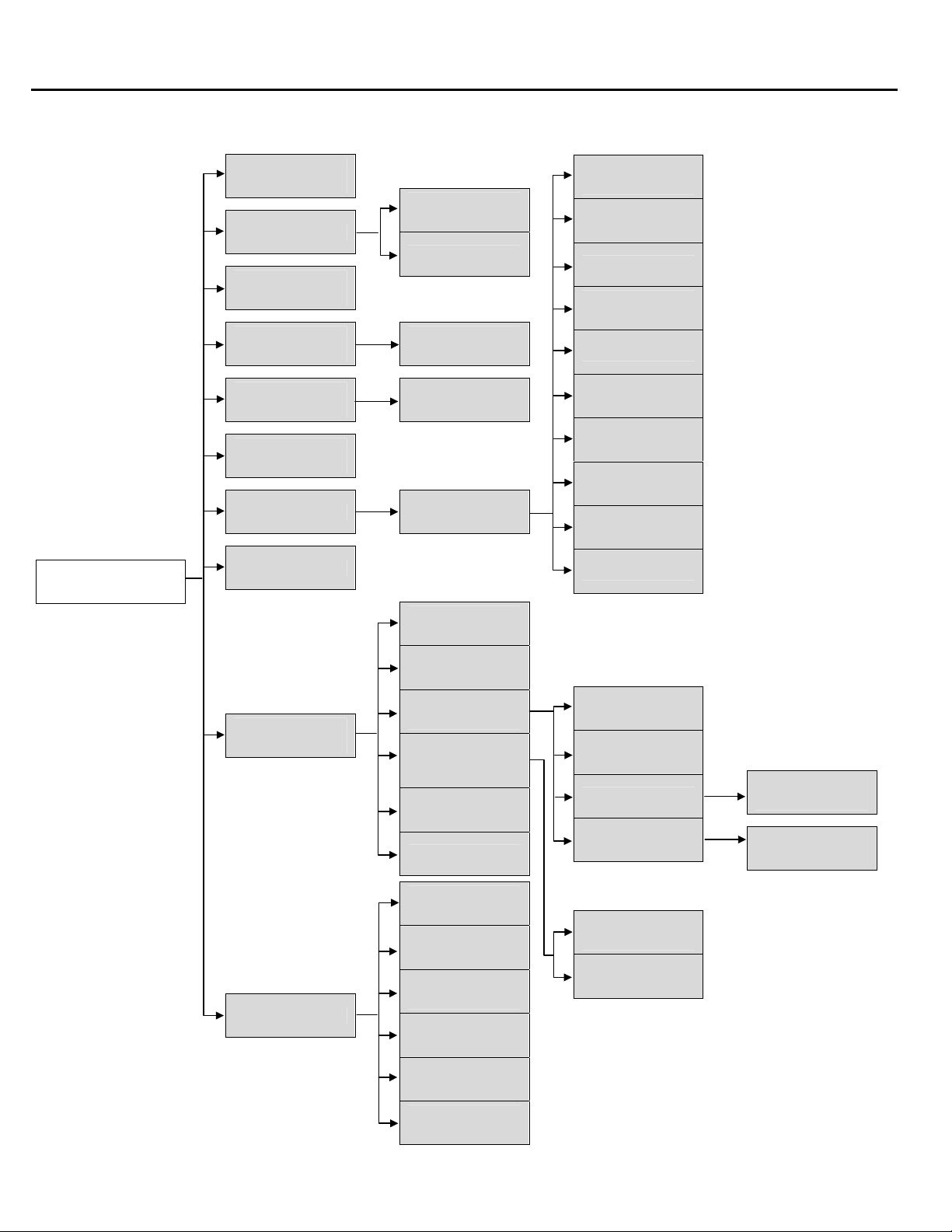
Figure 1: Administrative Menu Tree (Console) for the TVM-2000 Call Processing System
Security
Options
Operation Menu
Load Switch
Default
Configuration
Menu
Set Business
Hours
Holiday Setup
Fax
Configuration
Forwarding
Options
Mailbox
Greetings
Names
Personal
Operator
Notifications
Administrative
Main Menu
Port Specific
Options
Single Digit
Menu
Mailbox Setup
Reports
Advanced
Settings
VM Extensions
Edit Mailboxes
Switch
Configuration
Line ID
Mapping
More Switch
Configuration
Advanced
Switch
Configuration
Remote
Configuration
Video Options
Page
Hold Options
Mailbox
Attributes
Audiotext
Wake Up
Edit CP DTMFs
Rules
Hotel
Other
Admin
Extensions
PMS Setup
Backup
TVM-2000
Restore
TVM-2000
Manual PBX
Utilities
6 TVM-2000 Technical Reference Manual
Setup
Upgrade
TVM-2000
Disk
Defragment
Enable Remote
Maintenance
Standard
Parameters
Call Progress
Parameters
Page 21
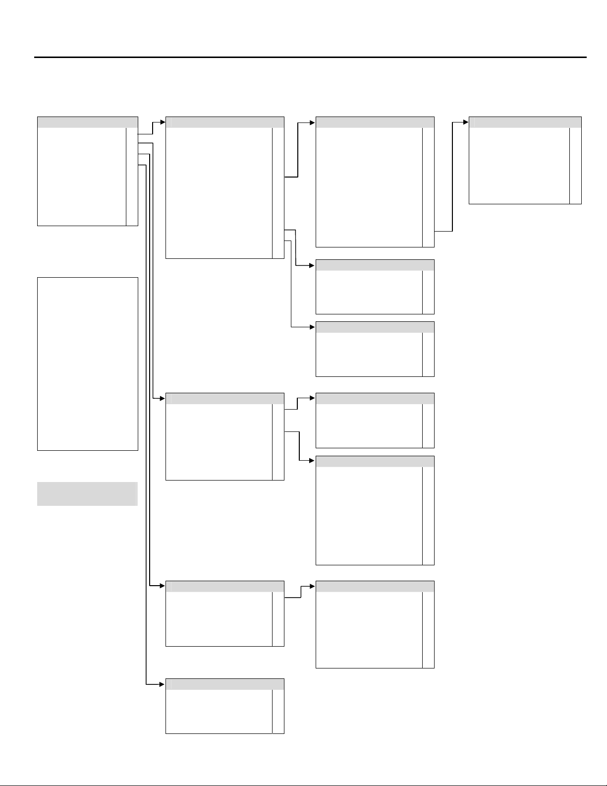
Figure 2: Administrative Options Menu
Overview of Features
Administrative Options
Mailbox Setup 1
System Setup 2
System Configuration 3
System Reports 4
System Backup 5
System Restore 6
Load Preset PBX* 8
Advanced Functions 9
Exit #
To access the
Administrative Options
Menu:
Call the Voice Mail System
Press the [*] key during the
greeting message.
When asked for your
mailbox number, enter 99 for
2-digit and 999 for 3-digit
systems.
Enter your access code.
From the Mailbox Owner’s
Menu, press 9 to reach the
Administrative Options
menu.
Options marked by “*” are
intended for use only by
Telekol Authorized Dealers.
Mailbox Setup
Activate a Mailbox 1
Cancel a Mailbox 2
Access Code 3
Outbound Dial Control 4
Set Mailbox Type 5
Set Record Time 6
Set Message Limit 7
Set Message Purge Time 8
Set Rings at Extension 9
More Options
Group Setup *
Exit #
System Setup
Set Day/Night 1
Set Special Greeting 2
Record Greetings 3
Set Business Hours 4
Set Single Digit Menu 5
Assign Single Digit Mailbox 6
Exit #
Mailbox Type
Normal 1
Day Transfer Only 2
Notify Before Connect 3
No Call Progress 4
Direct Access 5
Group 6
Speakerphone Announce 7
Voice Mail Only 8
Audiotext 9
0
Mailbox Type Cont. *
Exit #
More Options
Record Mailbox Greeting 1
Record Mailbox Name 2
Listen to Messages 3
Exit #
Group Setup
Review Group Members 1
Add Group Members 2
Delete Group Members 3
Exit #
Set Day/Night
Automatic 1
Day Mode 2
Night Mode 3
Exit #
Record Greetings
Day Greeting 1
Night Greeting 2
Special Greeting 3
Main Menu Part 1 4
Single Digit Menu 5
Main Menu Part 2 6
Multilingual Greeting 7
Greeting By Number 8
Exit #
Mailbox Type Cont.
Page 1
Urgent 2
Always Page 3
Alternate Msg. Notification 4
Skip Status 5
Call Screening 6
Exit #
System Configuration
Telephone Settings 1
Set 2 or 3 Digit Mailbox 2
Set Time 3
Set Date 4
Exit #
Reports
Mailbox Reports 1
Activity Report 2
System Reports 3
Exit #
Telephone Settings
Rings Before Answer 1
MWL On Sequence 2
MWL Off Sequence 3
Outbound Follow-Me Seq. 4
Beeper Sequence 5
Outbound Msg. Notify Seq. 6
Exit #
TVM-2000 Technical Reference Manual 7
Page 22

8 TVM-2000 Technical Reference Manual
Page 23

Hardware Installation
Overview
Installation of the TVM-2000 call processing system requires careful planning and execution.
Remove the unit from its packaging. The unit was fully inspected at NETXUSA before shipping. If
you find any damage, please save all original packaging materials and notify NETXUSA and the
shipper immediately. The following items are packed with each unit:
ITEM QUANTITY
System Unit 1
AC Power Cord 1
TVM-2000 Quick Reference Cards 5 per port
TVM-2000 System Administrator & Technical
Reference Manual
TVM-2000 User Guides 10 per every 4 ports
Section 1:
Express Install
1 for first time buyers
Installation Considerations
Use the following guidelines to choose a suitable location for your TVM-2000 unit:
• Avoid direct sunlight and extremely hot, cold or humid locations. Environment temperature
should be between 40 and 90 degrees Fahrenheit, and relative humidity between 10 and 90
percent.
• Avoid excessive dust and vibration.
• Avoid locations with abrupt temperature swings.
• Avoid power circuits with thermostat-controlled equipment or other equipment that draws large
currents.
Use of surge protection, uninterruptible power supply (UPS), and telephone line protection is
strongly recommended.
TVM-2000 Technical Reference Manual 9
Page 24

Section 1: Express Install
Planning
Follow the steps below to plan the elements and features of the voice mail system.
1. Review the Integration Notes for your particular telephone switch to determine the parameter
limits and features available. If it appears that your switch does not support a desirable feature,
the TVM-2000 may provide you with the ability to configure an alternate method by utilizing its
own internal hardware and software systems. See “Section 3: Using TVM-2000 Features” on
page 41 for more information on activating features using non-compliant switches.
2. Develop a list of existing extensions.
3. Ascertain the relationship(s) among extensions, e.g., John Smith is one of 25 extensions in the
Customer Service Department.
4. Work with the client to establish parameters and system-wide preferences.
5. Develop a call progress work flow diagram to find any possible “dead-ends” in your system.
Ensure that all caller options either end in a voice response or a voice mailbox, fax or fax
mailbox, or return the caller to the main menu.
Using “Appendix A: Worksheets” on page 145 will expedite the planning process.
10 TVM-2000 Technical Reference Manual
Page 25
Connecting to the Telephone System
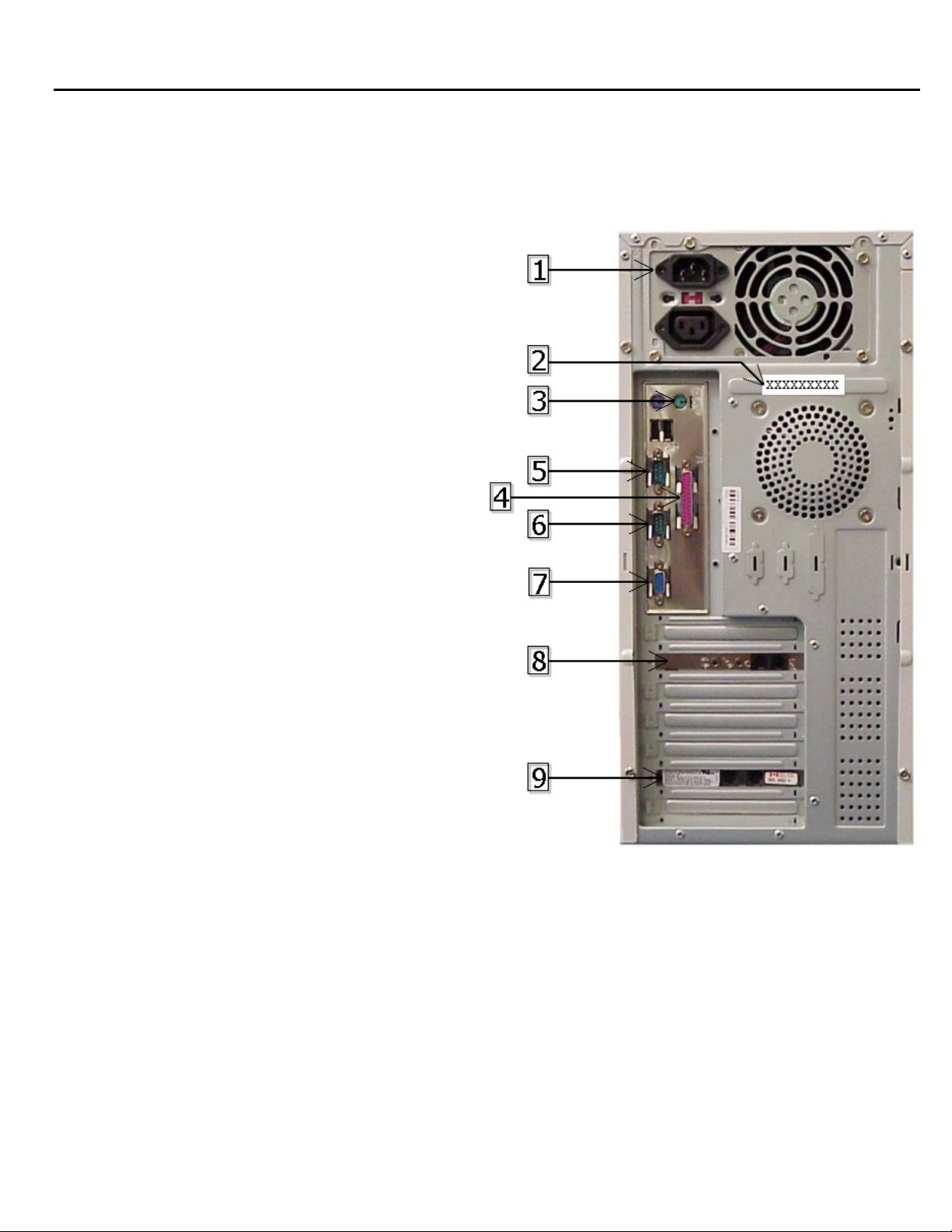
The following figure illustrates the physical connections in the tower required to set up the TVM2000 unit.
Key:
1. Power Connector
2. TVM Serial Number
3. Keyboard Connector
4. Parallel Printer
5. Serial Port 1 (COM 2)
6. Serial Port 2 (COM 1)
7. Monitor
8. Modem
9. 4-Port Voice Board
(2 RJ-14 port model shown)
Section 1: Express Install
Figure 1-1: TVM-2000 Physical Connections
TVM-2000 Technical Reference Manual 11
Page 26

Section 1: Express Install
Enabling Remote Maintenance (Optional)
Telekol recommends enabling the remote maintenance software that is shipped with your TVM-2000
unit. Follow the steps below to enable remote maintenance:
1. Refer to Figure 1-1 on page 11 to connect the modem or terminal.
2. Call the TVM from any touch-tone phone.
3. Press [*] at the TVM welcome message.
4. Enter [999], or [99] when asked for a mailbox number.
5. Enter [9876] (default) when asked for the access code.
6. Enter [9] when the Mailbox Owner’s Main Menu is listed.
7. From administrator’s Main Menu, enter [9].
8. Enter [1786] when asked for the default access code.
9. After the tone,
a. Select [841] for serial port if using a terminal or an external modem
b. Select [842] for internal modem.
10. Repeat steps 7 and 8 and press [9*] to activate the remote maintenance software.
11. Allow the TVM-2000 reset itself.
Configuring the Terminal (Optional)
If a terminal or terminal emulator from a laptop is being used, set the emulation to either VT-100 or
VT-102. Set the serial port for No parity, 8 data bits, 1 stop bit, and 19,200 baud.
Configuring the Modem (Optional)
Set the remote terminal to either VT-100 or VT-102 emulation. Dial the phone number of the line
connected to the TVM remote maintenance modem.
Connecting to Remote Maintenance (Optional)
After the connection has been established, press <Ctrl><A> four times (for null modem
connections only).
1. At the password prompt, enter JORDAN (default)
2. The TVM main menu will appear.
3. For security purposes, the system will automatically log off if no activity is detected after five
minutes. To re-access the system, press <CTRL><A> four times, and then enter the password
(for terminal only).
12 TVM-2000 Technical Reference Manual
Page 27

Powering Up
The TVM-2000 will run the following diagnostic programs during power up to optimize and verify
its disks, data, and directories:
1. ScanDisk checks for disk errors and automatically repairs them.
2. MDXCHK analyzes the databases.
Several LEDs will light as the system is booting up, and after about 30-50 seconds, the system will
sound three “beeps” indicating it is ready to accept calls.
Quitting the TVM-2000
Should powering down the TVM-2000 voice mail server ever become necessary, press <CTRL><q>
at the main menu then once at the “C:\TM\PROD>” prompt, turn the power off.
Modifying Screen Parameters
There are two types of parameters in the TVM-2000 interface; some parameters require that a value
be typed in, the others require toggling between values. To type in a value, position the cursor on the
desired parameter, then press the [ENTER] key to access the field. Use the [BACKSPACE] key to
delete an existing value and enter a new one. When finished, press the [ENTER] key to exit edit
mode. To toggle between values, press the [ENTER] key repeatedly. Pressing the [ESC] key from
any screen will produce the previous screen. Whenever changes are made, a new screen will appear
requesting confirmation of the change. Entering [Y] will save the changes. Entering [N] will cancel
the changes.
Section 1: Express Install
TVM-2000 Technical Reference Manual 13
Page 28
Section 1: Express Install
Main Menu
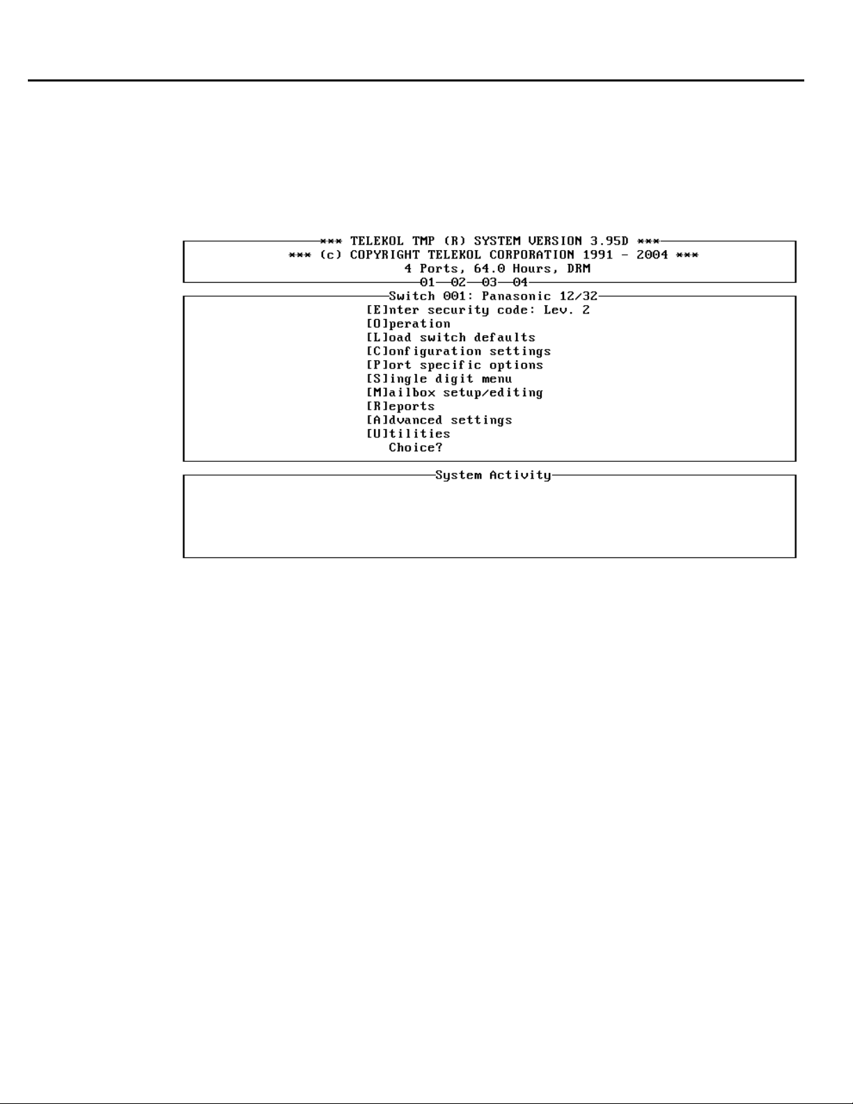
Your TVM-2000 voice mail software is loaded automatically whenever the TVM-2000 unit is
booted up. When the software has completely booted up, the TVM-2000 Main Menu screen will
appear. (If the optional Hospitality Module is installed, the Hospitality Main Menu screen will
appear instead.)
F igure 1-2: TVM-2000 Main Menu
The Main Menu is divided into three sections: System Information, System Setup/Options and System
ctivity.
A
he System Information Window is at the top of the screen. It displays general system information
T
cluding the software version number, number of ports, and the maximum storage capacity
in
urchased (the storage capacity is the number of hours available for recording messages and
p
greetings). Inverse video surrounding a port num
The System Setup/Option ns
f nt screen. To
rom the curre choose a particular option, type in the first letter of the option name.
T nd
he System Activity Wi ow is at the bottom of the screen. It shows the activity associated with
each port. This allows revi
n
otification, etc.
P at E
ressing [SPACE BAR]
BAR] he
again will return t
s Window is in the middle of the screen. It describes the available optio
ew of current system activities such as call progress, voice mail,
the main menu will enlarge the System Activity screen, pressing [SPAC
screen to its original state.
ber indicates that the port is processing a call.
14 TVM-2000 Technical Reference Manual
Page 29

Section 1: Express Install
FIELD DESCRIPTION
[E]nter Security Code Allows access to the administrative functions. It is recommended that
only authorized dealers change this parameter. The default is Level 2.
[O]peration Sets the system-wide parameters, e.g. Date, Time, Operator Mailbox
ID, Business Hours and Holidays
[L]oad Switch Defaults Enables automatic default parameter settings for individual telephone
switches through the entry of a switch default code found in the Preset
Switch Default Table.
[C]onfiguration
Settings
[P]ort Specific Options Enables and configures parameters and functions for individual Voice
[S]ingle Digit Screen Assigns and enables settings for the single digit Screen.
[M]ailbox Setup/Editing Activates, edits and deletes individual mailbox settings for all mailbox
[R]eports Lists the available reports about the system and its mailboxes and
[A]dvanced Settings Details advanced settings for entire TVM-2000 system.
[U]tilities Lists available utilities, such as backup, restore, upgrade, and routine
Sets Voice Mail specific system configuration options.
Mail ports or port groups, e.g., multi-tenant switch configurations.
types.
enables requests to be sent to printer or text file.
maintenance.
TVM-2000 Technical Reference Manual 15
Page 30
Section 1: Express Install
Loading Switch Defaults
Select a preset switch default that will integrate the TVM-2000 with your Private Branch Exchange
(PBX or “Switch”).
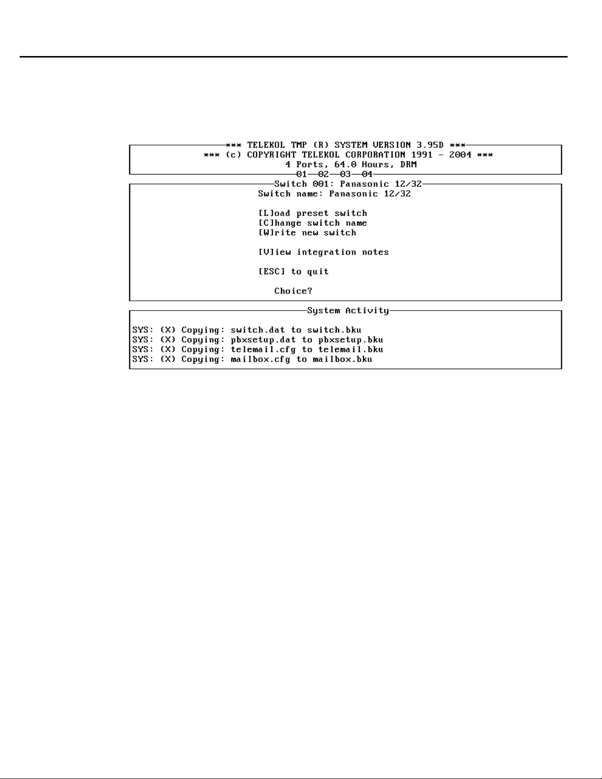
Figure 1-3: Load Switch Defaults Menu — To access from the Main Menu, press [L].
Use the Load Switch Defaults Menu to access the Load Switch Defaults screen. Select [L]oad Preset
Switch, and enter the Switch default number listed in the second to last column of the “Preset Switch
Settings Table”. (In cases where different switches share the same integration notes, you may have to
refer to the integration notes in order to find the correct switch default number.) Upon returning to
the Main Menu, you will notice that at the top of the System Setup/Options Window, the switch
name will have changed to the name of the switch selected.
The default switch settings are tailor-made to combine the TVM-2000 with each switch in the most
effective manner. Telekol recommends against changing any of the preset switch defaults.
Warning – Loading a switch default removes all Mailboxes and Settings.
TVM-2000 and Switch Integration
After loading the switch defaults using the switch number provided in the Preset Switch Defaults
Table, complete the integration as detailed in the Switch Integration Manual.
16 TVM-2000 Technical Reference Manual
Page 31
System Greetings
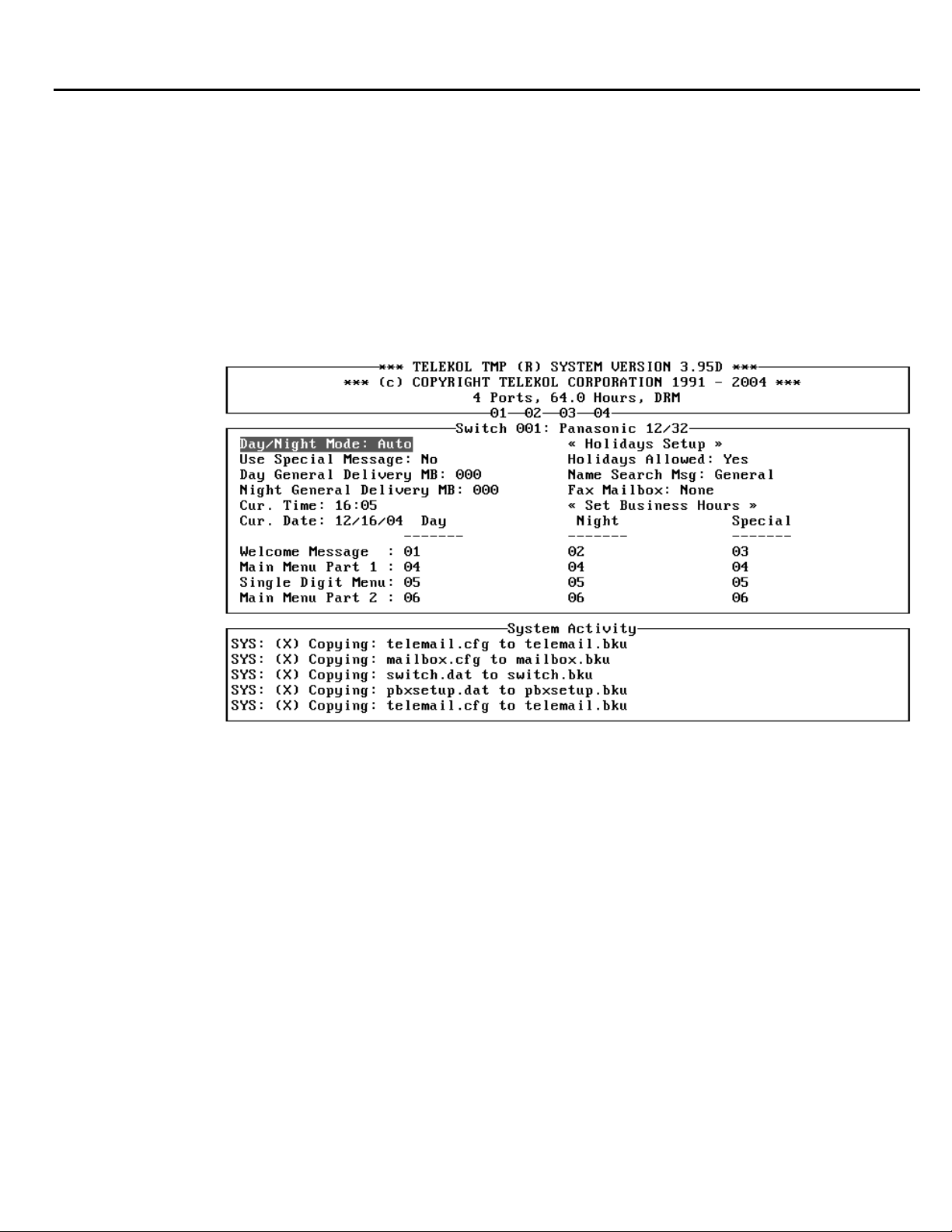
System Greetings are the initial greetings callers hear when they reach the TVM-2000. System
Greetings are composed from the Welcome Message, Main Menu Part 1, Single Digit Menu, and
Main Menu Part 2. Each of these greetings can be customized, numbered, and programmed to play
on different days or at different times of the day. The TVM-2000 concatenates these greetings and
plays them to the caller as if they were a single greeting.
Typical System Greeting structures use a total of 6 greetings and arrange them depending on the day
and time the call comes into the system. The order in which the messages are played are configured
via the Operations screen.
Section 1: Express Install
Figu re 1-4: Operations Screen — To access from the Main Menu, press [O].
TVM-2000 Technical Reference Manual 17
Page 32

Section 1: Express Install
Example:
ABC Corporation wants to greet callers with 3 different greetings depending on the time of day.
During the day, callers will hear:
Welcome to ABC Corporation. If you know your party’s extension number, you may dial it at
any time. For a company directory, dial 411. For sales, press 1, for technical support press 2,
for fax on demand press 3. If you need further assistance, please press 0 or stay on the line
for the operator.
After hours, callers will hear:
Welcome to ABC Corporation, our hours of operation are from 8:30 AM to 7:30 PM. If you
know your party’s extension number, you may dial it at any time. For a company directory,
dial 411.
During lunch, callers will hear:
Welcome to ABC Corporation, from 12 p.m. to 1 p.m. we are closed for lunch. If you know
your party’s extension number, you may dial it at any time. For a company directory, dial
411. For emergency technical support, press 7.
In order to do this, the administrator would record and label 6 greetings as shown below:
1. “Welcome to ABC Corporation”
2. “Welcome to ABC Corporation, our hours of operation are from 8:30 a.m. to 7:30 p.m.”
3. “Welcome to ABC Corporation, from 12 p.m. to 1 p.m. we are closed for lunch.”
4. “If you know your party’s extension number, you may dial it at any time. For a company
directory, dial 411.”
5. “For sales, press 1; for technical support, press 2; for fax on demand, press 3.”
6. “If you need further assistance, please press 0 or stay on the line for the operator.”
The greetings could then be arranged as shown in the matrix in figure 1-4. The greeting for each
mode is the concatenated greetings in the column for that time of day. The TVM-2000 allows for
the same greeting number to be used during different times of the day thereby increasing
flexibility in rearranging and recording greetings.
Note: If only one greeting is recorded, the greeting number should be put in the “Main Menu
Part 1” row on the Operations screen.
Recording System Greetings (Telephone Interface)
Record your greetings from the TVM-2000’s Administrative menus. The administration mailbox
number is 99 or 999. (“Greeting Scripts” on page 154 can be used to plan your greetings before you
record them.)
To access the Administrative Options Menu, perform the following steps:
1. Call the TVM-2000 from any touch-tone phone.
2. Press [*] at the TVM-2000 welcome message.
3. Dial [9]+[9]+[9] (for 3 digit dialing plan) when asked for a mailbox number.
4. Enter [9]+[8]+[7]+[6] (default) when asked for the access code.
5. Enter [9] when the Mailbox Owners Main Menu is played.
After you access the administration side, the Administration Options Menu will play. Press [2], [3] to
access the Record System Greetings menu. Select option 8 if you are recording by number. After
recording, the TVM-2000 will offer you four options:
• To listen to your greeting, press [1]
• To save your greeting, press [2]
• To record your greeting again, press [3]
• To exit without saving, press [4]
18 TVM-2000 Technical Reference Manual
Page 33
Section 1: Express Install
Using Pre-Recorded Greetings
Some dealers and customers prefer using professionally recorded greetings instead of recording
System Greetings through the telephone. If you wish to have your greetings professionally
recorded, first make sure that your vendor can digitize recordings into 8 bit, 8 kilohertz PCM mulaw files. The files can then be labeled according to the numbers used in the matrix on the
operations screen (01.msg, 02.msg, etc.). Once the greetings are labeled, shut down the TVM2000 and place the files in the c:\tm\msg\ directory. The new greetings will be used once the
TVM-2000 is re-started.
Setting Operation Modes
The next step in setting up the initial system greetings is to tell the TVM-2000 when to play day,
night and special messages.
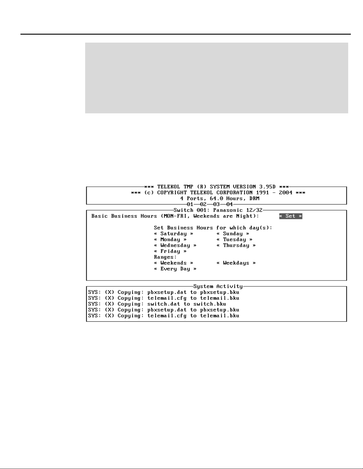
1. On the Operations screen, make sure the Day/Night Mode field is set to “Auto” (default).
2. From the Operations screen, access the Set Business Hours screen.
Use the Set Business Hours screen to configure Day, Night, and Special time ranges.
3.
Figure 1-5: Set Business Hours Menu — To access from the Main Menu, press [O], «Set
Business Hours».
TVM-2000 Technical Reference Manual 19
Page 34

Section 1: Express Install
Setting Up Operator (General Delivery) Mailboxes
The first mailboxes to set up are the Operator, or General Delivery mailboxes. These are the default
mailboxes used, for example, when the caller selects no options or the mode of operation dictates a
transfer to a general delivery mailbox, such as during holidays.
Before working on a mailbox, it must be created via the Mailbox/Setup Editing screen.
Set the mailbox number for Day or Night mode by entering the operator’s mailbox in the Day
General Delivery MB and the Night General Delivery MB fields on the Operations Screen.
Fax Detection
The TVM-2000 base unit includes the ability to detect Fax calls (CNG tones) and transfer them to a
fax machine. (For information on setting up the additional features included with the Optional Fax
Module, see “Fax Module” on page 52.)
1. From the Main Menu, select [M]ailbox Setup/Editing.
2. Select a MB to which Fax calls will be transferred.
3. Access the Mailbox Attributes screen.
4. Activate (put a “*” next to) the NoCallProgress field.
5. From the Main Menu, select [O]perations.
6. Enter the number of the fax mailbox in the Fax Mailbox field.
20 TVM-2000 Technical Reference Manual
Page 35
Company Directory Options
The last step in your express setup is to specify your company directory options. The TVM-2000 can
be configured to allow callers to access a directory of telephone extensions through the Name Search
screen, and can be further configured to perform special functions if there is more than one person at
a company with the same first or last name.
Section 1: Express Install
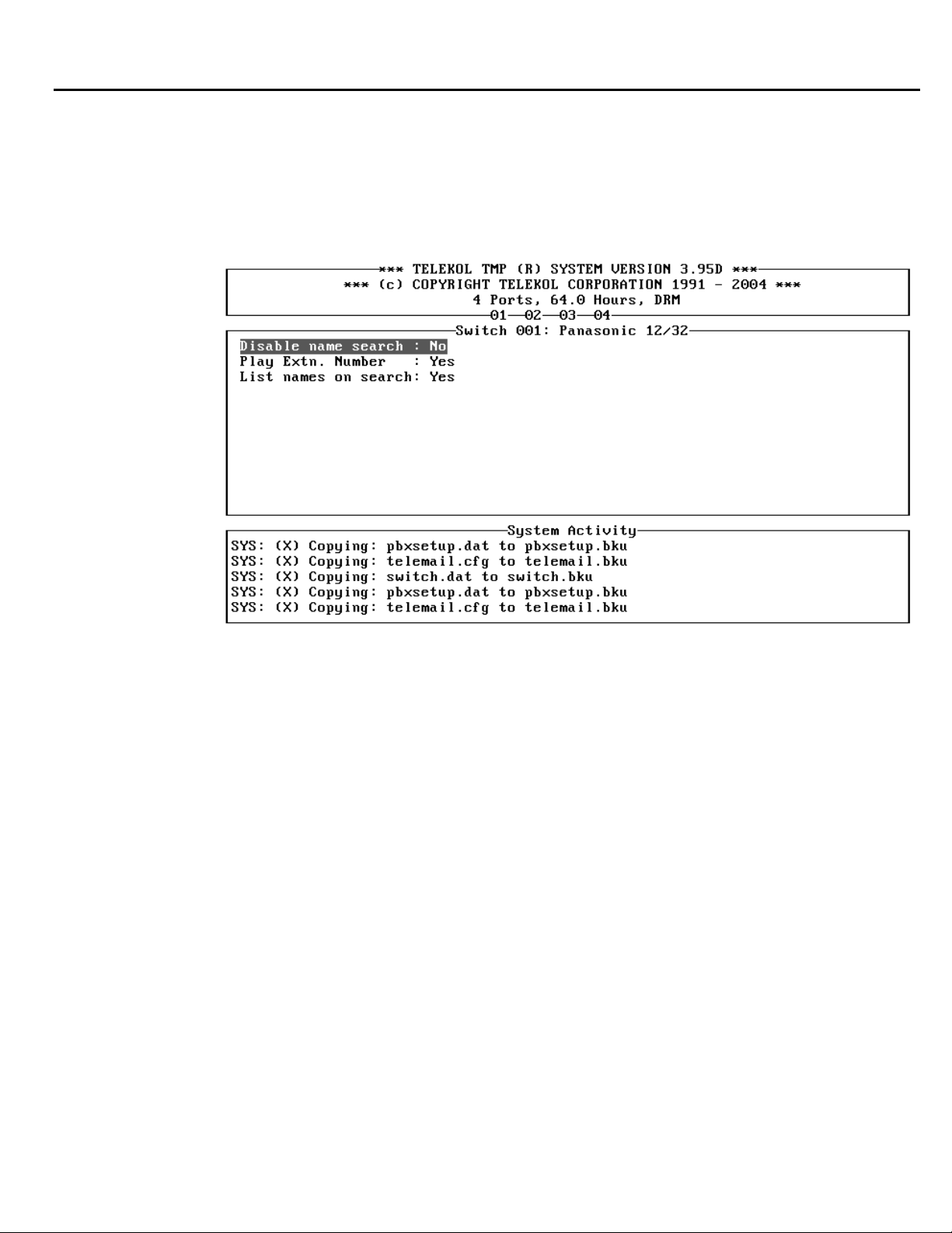
Figure 1-6: Name Search Screen — To access from the Main Menu, press [C], «NameSearch».
The Company directory allows callers to find their party by name. There are five fields that control
the behavior of the Directory feature:
Disable Name Search Name Search screen
Toggles on or off (activating or deactivating) the Directory Option.
Hide Extension Number Name Search screen
When set to “No” (default), this parameter allows the TVM-2000 to reveal the extension number of
the called party to the caller, i.e., “You are being transferred to extension 111, John Smith.” When
set to “Yes”, the caller is simply put through to the called party without first learning the extension
number, i.e., “You are being transferred to John Smith.”
TVM-2000 Technical Reference Manual 21
Page 36

Section 1: Express Install
List Names on Search Name Search screen
This parameter overrides the Operations screen’s Name Search Msg field and works in two separate
ways after more than one name in the Corporate Directory is identified as matching the caller’s
entry:
“Yes”: (default) After the caller is instructed to enter the first three letters of the name of the person
she/he is trying to reach, the TVM-2000 announces if the person you are trying to reach is <recorded
name>, press [1]. If the name identified is incorrect, the caller is asked to press [2]. If there is more
than one person with a last name that matches the caller’s entry, the TVM-2000 system then plays
the next person’s name, until no additional names are identified. At that point, the Voice Mail plays a
message that no match was found, and the caller is returned to the main menu to review the other
options.
“No”: The caller is instructed to enter the first three letters of the last name of the person she/he is
trying to reach. If more than one person is identified by the caller’s entry, the Voice Mail then asks
for the first three letters of the first name, and then the middle initial until no additional names are
identified. At that point, the Voice Mail plays a message that no match was found.
Follow the following steps to complete the setup of the Company Directory:
1. Enter the Configuration Settings screen by pressing [C] from the Main Menu.
2. Set the Directory MB field to the digits the caller needs to enter in order to access the directory.
By default this field is set to 002.
3. Enter the Operations screen by pressing [O] from the main menu.
4. Highlight the Name Search Msg field. This field controls the message that is played when the
caller reaches the directory.
5. Instruct each Mailbox Owner to enter his or her name in the corporate directory by following the
directions in the TVM-2000 User’s Guide.
Warning — Names will not show up in the name search unless they are entered and recorded.
Directory MB Configuration screen
This field determines the digits the caller needs to enter to access the company directory.
Name Search Msg Operations screen
This field controls the message that is played when the caller reaches the directory. This field may be
set as follows:
1. “General”: Prompts the caller to enter up to the first three letters of the first or last name of the
person they are trying to reach.
2. “First”: Prompts the caller to enter up to the first three letters of the first name of the person they
are trying to reach.
3. “Last”: Prompts the caller to enter up to the first three letters of the last name of the person they
are trying to reach.
22 TVM-2000 Technical Reference Manual
Page 37

TVM-2000 Technical Reference Manual 23
Page 38

24 TVM-2000 Technical Reference Manual
Page 39
The TVM-2000 uses three types of mailboxes: User Mailboxes, Audiotext Mailboxes, and Group
mailboxes. User Mailboxes are set up to serve as separate, private answering machines for each
company employee. Audiotext Mailboxes can be set up to play recorded announcements or
information to callers. Group mailboxes are used to route calls and messages to specific groups of
employees.
Setting Up User Mailboxes
Each preset switch default comes with a usable range of Mailbox numbers. Use “
Owner/Attributes Information
number can, but does not necessarily have to be, the same as the extension number. Once mailbox
and extension numbers have been assigned, follow the steps below to activate mailboxes for each
employee:
1. Enter the [M]ailbox Setup/Editing screen from the Main Menu.
Section 2:
Mailbox Setup
Mailbox
” on page 150 to assign each employee a mailbox. The mailbox
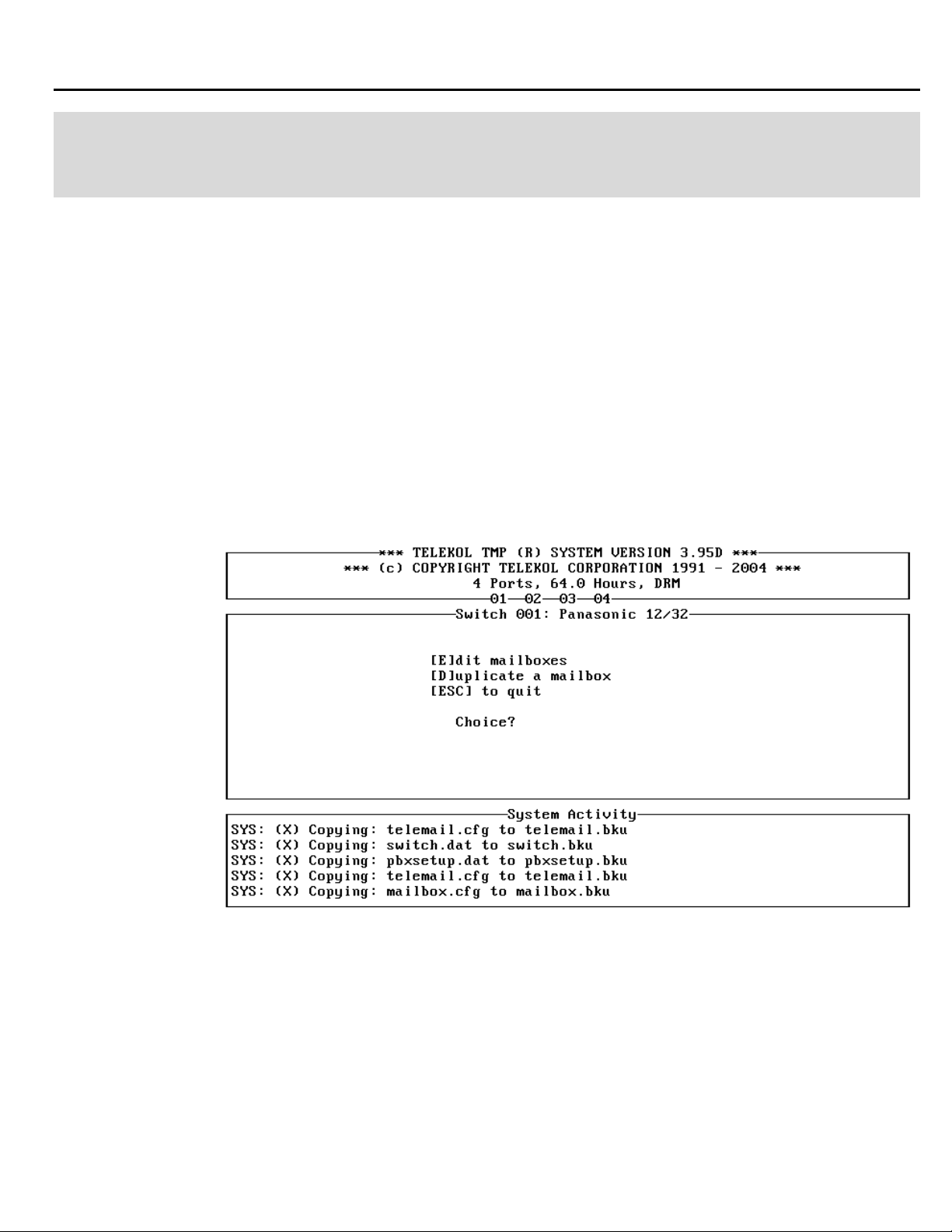
Figure 2-1: Mailbox Menu — To access from the Main Menu, press [M].
TVM-2000 Technical Reference Manual 25
Page 40
Section 2: Mailbox Setup
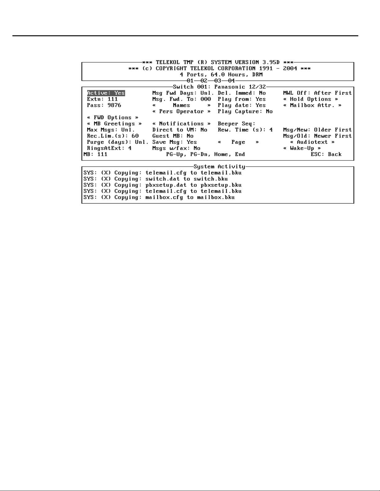
2. Enter the [E]dit Mailboxes screen, shown below:
Figure 2-2: Mailbox Editing Screen — To access from the Main Menu press [M], [E], mailbox
#, [ENTER].
3. Enter the mailbox number that you wish to edit.
. Enter the employee’s extension number in the Extn: field at the top of the left column on the
4
screen.
5. Access the Names screen
6. Enter the employee’s last and first name in the Last Name and First Name fields, respectively.
Changing the rest of the fields on Mailbox Editing screen is optional. Which fields will require
changing depends primarily on the specific application you are setting up. Contact your Telekol
Authorized Dealer for details.
Assigning a Personal Operator for an Individual Mailbox
A personal operator can be assigned for any mailbox. To assign a personal operator to a mailbox:
1. From the Main Menu, press [M] for Mailbox Setup/Editing.
2. Press [E] to Edit Mailboxes.
3. Enter the number of the mailbox for which you want to assign a Personal Operator.
4. Access the Personal Operator screen from the Mailbox Editing screen
5. In the Personal Operator field, enter “Yes”.
6. In the Personal Operator MB field, enter the Personal Operator’s MB number.
TVM-2000 will not allow you to assign a non-active mailbox as a personal operator.
26 TVM-2000 Technical Reference Manual
Page 41
Section 2: Mailbox Setup
Setting up Hold Options for Each Mailbox
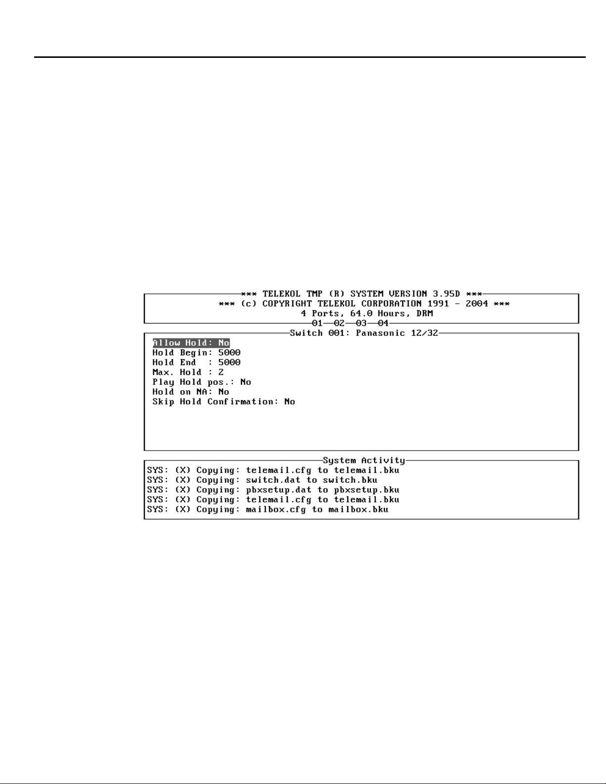
The Hold Options screen controls whether or not callers to a particular mailbox are allowed to hold
in queue.
The first caller on hold in queue is on hold in the switch. All other callers are held in the Voice
Mail.
To enable hold options for a particular mailbox, follow the steps below:
1. Type [M] from the Main Menu to enter the Mailbox Editing screen.
2. Type [E] from the Mailbox Editing screen.
3. Enter the number of the mailbox that will use Hold Options.
4. Access the «Mailbox Attr.» screen.
5. If there is a star to the left of NoCallProgress, deactivate it. You must have supervised transfers
enabled for hold options to work on this mailbox. Consult the Switch Integration Manual to
determine how to enable supervised transfers for your PBX.
6. Press [ESC] and then enter the «Hold Options» screen from the Mailbox Setup/Editing screen.
Figure 2-3: Hold Options Screen — To access from the Main Menu press [M], [E], mailbox #,
«Hold Options».
7. Set the Allow Hold field to “Yes.”
8. [ESC] out and save your changes.
TVM-2000 Technical Reference Manual 27
Page 42
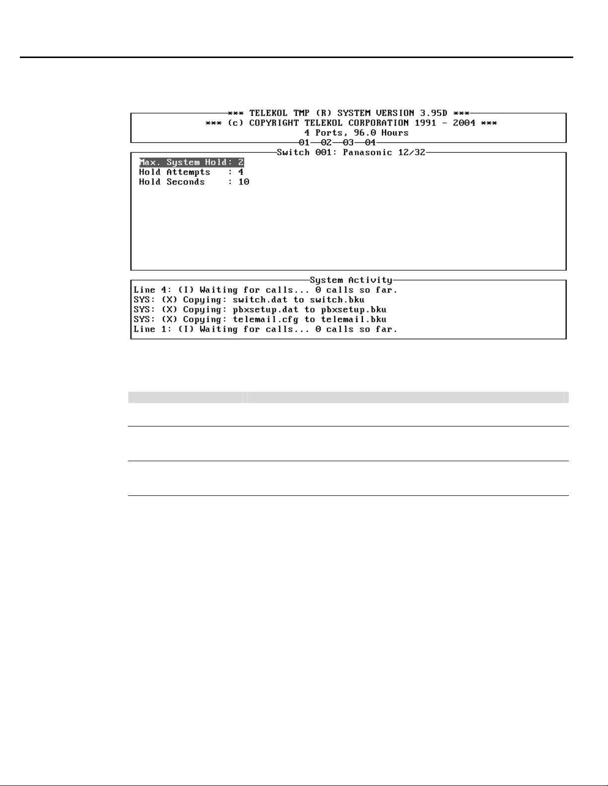
Section 2: Mailbox Setup
9. From the Main Screen, enter the Configuration screen by typing [C].
10. Enter «Hold Options».
Figure 2-4: System Hold Options Screen — To access from the Main Menu press [C], «Hold
Options».
FIELD DESCRIPTION
Max System Hold The maximum number of callers allowed to hold in the system queue
at the same time. Limited to the number of ports.
Hold Attempts Sets the number of times the TVM-2000 attempts to transfer the caller
to a busy extension before prompting the caller with an option to
continue holding.
Hold Secs. When using hold options, this field sets the length of time the system
waits before retrying a busy extension. Do not set higher than the
default value of 10.
11. In the phone switch, disable call forwarding on all stations which have hold options enabled in
order to prevent callers on hold from being forwarded to another extension.
For a complete explanation of all the fields listed on the Hold Options and Configuration screens, see
“System Hold Options Screen” on page 98 and “Configuration screen” on page 95.
Telekol ships “Hold Music” with every TVM-2000 unit. The Hold Music is stored in message
numbers 5000 through 5009.
28 TVM-2000 Technical Reference Manual
Page 43

Activating Optional Mailbox Features
Notification Options
The TVM-2000 can be set up to notify mailbox owners of incoming calls and waiting messages
using a variety of options.
Beeper Notification Option
The Beeper Notification Option programs the TVM-2000 to beep Mailbox Owners whenever
messages are left for them. Follow the steps below to configure the Beeper Notification Option:
1. Enter the Configuration screen by pressing [C] from the Main Menu.
2. In the Beeper Seq field, enter the appropriate string of dialing codes. For a list of dialing codes,
see “Dialing Codes” on page 173.
3. From the Main Menu, enter the Mailbox Editing screen by pressing [M], [E].
4. Enter the number of the mailbox that will be given beeper notification.
5. Access the «FWD Options» screen.
6. Set the Outbd Fwd Ok field to “Yes”.
7. Set the Fwd field to “Beeper”.
8. Enter the phone number of the beeper in the Fwd Num field. Please note that this number
should be entered as it would be dialed. Do not include any digits required for an outside line by
the switch.
9. (Optional) At this point, the mailbox is configured to notify the mailbox owner on all messages.
To configure the mailbox to perform beeper notification on urgent messages only, enter the
«Mailbox Attr.» screen and activate (place a “*” next to) the Urgent OK field.
There are several fields that affect beeper notification and its behavior. Review each of the following
fields to ensure efficient processing:
[M]ailbox Setup/Editing screen
Beeper Seq.: The individual mailbox owner’s beeper number sequence. If it is blank, the value
entered in the Beeper Seq. field on the Configuration screen is used.
Play Capture: When set to “Yes,” Voice Mail will play the captured DTMFs as the message.
«Notifications»
Not. Del.: The number of minutes the Voice Mail waits before performing the beeper notification
procedure.
Num Notifys: The number of times the Voice Mail performs the beeper notification procedure if the
message is not retrieved.
Notify Mins: The amount of time the Voice Mail waits before initiating another beeper notification
procedure if the message is not retrieved.
«Mailbox Attr» screen
Capture Digits: When enabled, allows callers to enter the DTMFs that will appear as the number to
call in the beeper window.
Urgent Ok: When enabled, mailbox owners will only be notified of messages left in their mailbox
that are marked “Urgent”.
Section 2: Mailbox Setup
TVM-2000 Technical Reference Manual 29
Page 44

Section 2: Mailbox Setup
[C]onfiguration screen
Notification Cycle: Global Parameter-Number of minutes the Voice Mail waits before performing
beeper notification, outbound message notification, call forwarding procedures, etc.
Beeper Seq.: Global Parameter-The default beeper number sequence.
Outbound Message Notification
When outbound message notification is enabled, the mailbox owner receives calls to the outside line
specified in the Fwd Num field. If the call connects, two methods of notification can occur. If “*4”
is the last part of the sequence string in the Outbound Dialing Seq., the call connects, the Voice Mail
hears the connection, and the recorded prompts instruct the mailbox owner how to retrieve the
message on the same call. If “*6” is the last part of the sequence, the call connects, the Voice Mail
notifies the mailbox owner that she/he has a message waiting, and hangs up.
1. Enter the Advanced Settings menu by pressing [A] from the Main Menu.
2. Enter the Switch Configuration screen by pressing [S] from the Advanced Settings menu.
3. In the Outbd Dialing Seq. field, enter the appropriate string of dialing codes. For a list of
Dialing Codes, see “Dialing Codes” on page 165.
4. Press [Esc] to go back to the Main Menu.
5. From the Main Menu, press [M] for Mailbox Setup/Editing.
6. Press [E] from the Mailbox Setup/Editing screen.
7. Enter the number of the mailbox that will be given Outbound Message notification functionality.
8. Access the «FWD Options» screen.
9. Set the Outbd Fwd Ok field to “Yes.”
10. Set the Fwd field to “Out-Msg Notif.”
11. Enter the phone number of the external location in the Fwd Num field. Please note that this
number should be entered as it would be dialed. Do not include any digits required for an outside
line by the switch.
12. (Optional) At this point, the mailbox is configured to notify the mailbox owner on all messages.
To configure the mailbox to perform out bound message notification on urgent messages only,
highlight «Mailbox Attr.» and press [ENTER].
13. (Optional) Highlight Urgent OK and press [ENTER] to activate this attribute.
30 TVM-2000 Technical Reference Manual
Page 45

Section 2: Mailbox Setup
There are several options that affect outbound message notification and its behavior. Review each of
the following fields to ensure efficient processing:
«FWD Options» screen
Outbd Fwd Ok: When set to “Yes,” Voice Mail is enabled to deliver messages and transfer calls to
off-site telephone numbers and beepers.
Fwd: Indicates the type of forwarding enabled for this particular mailbox. It should be set to “OutMsg Notif”.
Fwd Num: The off-site telephone number to which the message notification is being sent.
«Notifications» screen
Not. Del.: The number of minutes the Voice Mail waits before performing the outbound message
notification procedure.
Num Notifys: The number of times the Voice Mail performs the outbound message notification
procedure if the message is not retrieved.
Notify Mins: The amount of time the Voice Mail waits before initiating another beeper notification
procedure if the message is not retrieved.
[M]ailbox Editing Screen
Play Capture: When set to “Yes,” Voice Mail will play the captured DTMFs as the message.
«Mailbox Attr»
Urgent Ok: When enabled, mailbox owners will only be notified of messages left in their mailbox
that are marked “Urgent”.
[C]onfiguration screen
Notification Cycle: A global parameter that sets the number of minutes the Voice Mail waits before
performing outbound message notification.
TVM-2000 Technical Reference Manual 31
Page 46

Section 2: Mailbox Setup
Outbound “Follow-Me” (Call Forwarding)
Outbound Follow-Me allows the TVM-2000 to put an incoming call on hold, dial an outside line and
connect to a telephone off-site, verify the connection and connect the caller to that outside telephone.
To properly configure the TVM-2000 to initiate an out bound message notification session, the
Switch and CO line must support unsupervised trunk-to-trunk transfers (such as Centrex).
1. Enter the Advanced Settings screen by pressing [A] from the Main Menu.
2. Enter the Switch Configuration screen by pressing [S] from the Advanced Settings menu.
3. In the Outbd Follow-Me Seq. field, enter the appropriate string of dialing codes. For example,
the Outbd Follow-Me Sequence may look like: 9*1*9*4*3. The first 9 in this example is used to
secure a CO line. For a list of Dialing Codes, see “Dialing Codes” on page 165.
4. From the main menu, press [M] for Mailbox Setup/Editing.
5. Press [E] to access the Mailbox Editing Screen.
6. Enter the number of the mailbox that will be given Outbound Follow-me functionality.
7. Access the «FWD Options» screen
8. Set the Outbd Fwd Ok field to “Yes” by highlighting the field and pressing [ENTER].
9. Set the Fwd field to “Out-Follow.”
10. Enter the phone number of the external location in the Fwd Num field. This number should be
entered as it would be dialed. Do not include any digits required for an outside line by the
switch.
There are several options that affect Outbound Follow-Me and its behavior. Review each of the
following fields to ensure efficient processing:
«FWD Options» screen
Outbd Fwd Ok: When set to “Yes”, Voice Mail is enabled to deliver messages and transfer calls to
off-site telephone numbers and beepers.
Fwd: Indicates the type of forwarding enabled for this particular mailbox. It should be set to “OutFollow”.
Fwd Num: The sequence string matching the off-site telephone number to which the calls are being
transferred.
[S]witch Configuration screen
Outbd Follow-Me Seq: Sequence string matching the off-site telephone number to which the call is
to be transferred.
Outbd Port: Port assigned for automatic call forwarding, message, and beeper notification.
«Other» screen
Outbd Recall: Sequence string for retrieving a caller on hold in the Voice Mail when the outbound
call fails to connect.
Outbd Connect: Sequence string for connecting a caller on hold in the Voice Mail when the
outbound call connects.
32 TVM-2000 Technical Reference Manual
Page 47

Section 2: Mailbox Setup
Call Recording and Call Screening
Call Recording is most effective when combined with Speakerphone Announce and Call Screening.
The caller dials the desired extension and is prompted to speak his/her name. When the incoming call
is picked up by the extension, the Voice Mail will prompt the called party with: “Call from (caller’s
name). To save a recording of this call, press [1]. To tentatively record this call, press [2]. To not
record this call, press the [#] key.” If [1] or [2] is selected, the TVM-2000 will record both sides of
the conversation.
Enabling Call Recording requires switches that support “Supervised Transfers”. Check the Switch
Integration Notes for each switch that doesn’t support Supervised Transfers for additional
instructions on enabling Call Recording.
1. From the Main Menu screen, press [M].
2. Type [E] from the [M]ailbox Setup/Editing menu.
3. Enter the number of the mailbox that will be used.
4. Highlight «Mailbox Attr» and press [ENTER].
5. Activate (put a “*” next to) the Speakerphone field.
6. Activate (put a “*” next to) the Call Screening field.
7. Activate (put a “*” next to) the Call Recording field.
There are several options that effect two-way call recording and its behavior. Review each of the
following fields to ensure efficient processing: Refer to your telephone switch manual for the
specific DTMFs to use for the following parameters.
• Conference Seq.: This field indicates the digits the system automatically dials to initiate a two-
way call recording session. If left blank (default), the Voice Mail interprets this to mean a flashhook.
• Drop Conf. Seq.: This field indicates the digits the system automatically dials to disconnect
from a two-way call recording session. The Voice Mail stops recording, e.g., due to reaching the
maximum number of seconds of silence, but the call progresses. The two parties continue the
conversation. If left blank (default), the Voice Mail hangs up.
• Disc./Conf Seq.: This field indicates the digits the system automatically dials to abandon all
parties in a two-way call recording session. If left blank (default), the Voice Mail hangs up.
• RSilCallRec: ([A]dvanced Settings, [A]dvanced Switch Configuration, [S]tandard Parameters)
This field indicates the maximum number of seconds of silence allowed before the Voice Mail
assumes the call is over and stops recording. This setting is especially important since silences in
conversation can be much longer than those during the leaving of a message.
TVM-2000 Technical Reference Manual 33
Page 48
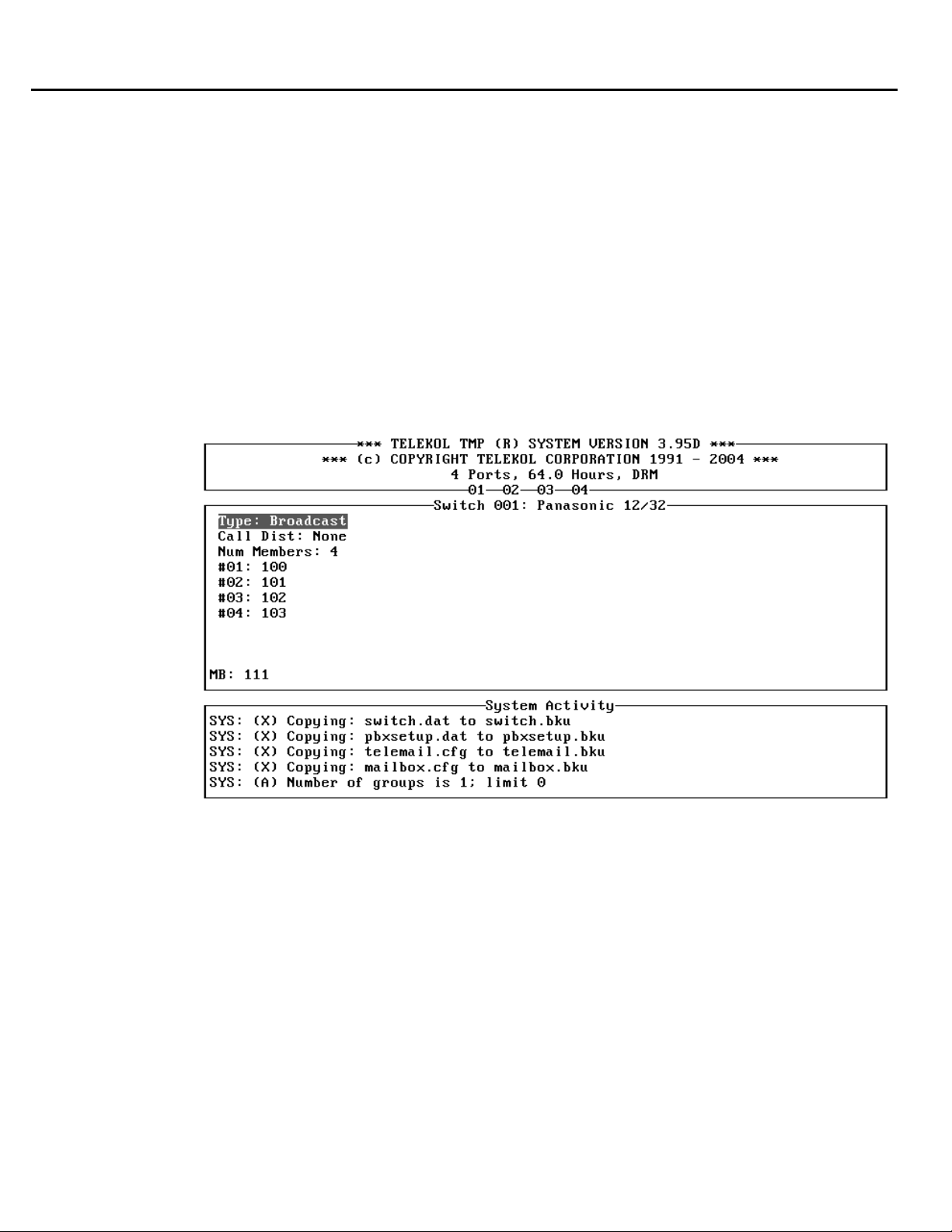
Section 2: Mailbox Setup
Group Mailboxes
Group Mailboxes are set up to allow several people to handle calls from a single mailbox. To set up
a group mailbox, follow the steps below:
1. Access an existing or create a new mailbox. For information on accessing or creating mailboxes,
see “Setting Up User Mailboxes” on page 25.
2. Access the «Mailbox Attr.» screen.
3. Activate (put a “*” next to) the Group field.
4. Press [Esc] to return to the Mailbox Editing screen.
5. Access the «Group Setup» screen, shown below. There are three fields on the Group Setup
screen that configure your group mailbox. The first, Type, controls the type of distribution of
calls or messages. The second, Call Distribution, controls how the calls or messages are
distributed to the group’s members. The third, Num Members, sets the number of members in
the group.
Figure 2-5: Group Setup Screen — To access from the Main Menu press [M], [E], mailbox #,
«Group Setup» for a mailbox with Groups enabled.
To access the Group Setup screen, the mailbox must first have “groups” enabled. The group field
is enabled via the «Mailbox Attr.» screen, which is also accessed through the mailbox editing
screen.
34 TVM-2000 Technical Reference Manual
Page 49

Group Types
Section 2: Mailbox Setup
Broadcast Groups
Messages left in Broadcast Group mailboxes are sent (broadcast) to every member within the group.
When a member of the group listens to the message, the message remains in all other mailboxes in
the group.
1. From the Mailbox Editing screen, highlight «Group Setup» and press [ENTER].
2. Enter “Broadcast” in the Type field.
3. Change the Num Members field to reflect the number of members in the group. TVM-2000
systems have a maximum of 40 members per group.
4. Enter the group members in the corresponding fields.
Dispatch Groups
Messages left in a dispatch group mailbox are sent to every member within the group. Once a
member of the group listens to the message, the message is removed from all other mailboxes in the
group.
1. From the Mailbox Editing Screen, highlight «Group Setup» and press [ENTER].
2. Enter “Dispatch” in the Type field.
3. Change the Num Members field to reflect the number of members in the group.
4. Enter the group members in the corresponding fields. Enter the members in the order in which
you wish to have them notified of a caller.
Retrieval Groups
Retrieval Groups are used to retrieve messages from several mailboxes in one step. Accessing the
owner’s side of the mailbox will allow the listener to hear all messages left for all the members of the
group. While accessing messages from one mailbox, the mailbox owner can press the star (*) key to
go to the next mailbox in the group.
1. From the Mailbox Editing Screen highlight «Group Setup» and press [ENTER].
2. Enter “Retrieval” in the Type field.
3. Change the Num Members field to reflect the number of members in the group.
4. Enter the group members in the corresponding fields.
Automatic Call Distribution (ACD) Only Groups
ACD Only groups distribute calls to the members of its group. These mailboxes handle messages as
a non-Group mailbox would. This type of mailbox has Group Mailbox functionality only insofar as
the Call Distribution field specifies.
1. From the Mailbox Editing Screen, highlight «Group Setup» and press [ENTER].
2. Enter “ACD Only” in the Type field.
3. Select the type of Call Distribution. See Call Distribution Types below.
4. Change the Num Members field to reflect the number of members in the group.
5. Enter the Group members in the corresponding fields.
TVM-2000 Technical Reference Manual 35
Page 50

Section 2: Mailbox Setup
Call Distribution Types
The Call Distribution field handles how group mailboxes distribute calls.
Top Down
Calls to group mailboxes with “Top Down” call distribution are distributed to the same extension in
the group in the same order. Each new call that comes in is routed to the same first extension each
time.
Uniform
Calls to group mailboxes with “Uniform” call distribution are distributed to group members in
sequential order. For each new call that comes in, the mailbox checks the last place to which it
transferred a call and begins hunting at the next Group Mailbox member.
Example: Top Down vs. Uniform
A mailbox group has members A, B, C, and D. If the group were set up as a “Top Down”
mailbox, incoming calls would always be first routed to mailbox A. If mailbox A was busy, the
call would be routed to B, then C, and finally D. The next incoming call would again be routed
first to extension A. If the group were set up as a “Uniform” mailbox, the first incoming call
routed to A. If mailbox A was busy, the call would be routed to B, then C, and finally D. The
NEXT incoming call would be routed to B. If B was busy, the call would be routed to C, D, and
finally A. The next incoming call would start off with C, etc.
Make sure NoCallProgress is NOT activated (there is no “*” next to NoCallProgress) if either Top
Down or Uniform groups are used.
None
Calls to ACD Only mailboxes with “None” selected route calls as any other non-Group mailbox
would.
36 TVM-2000 Technical Reference Manual
Page 51
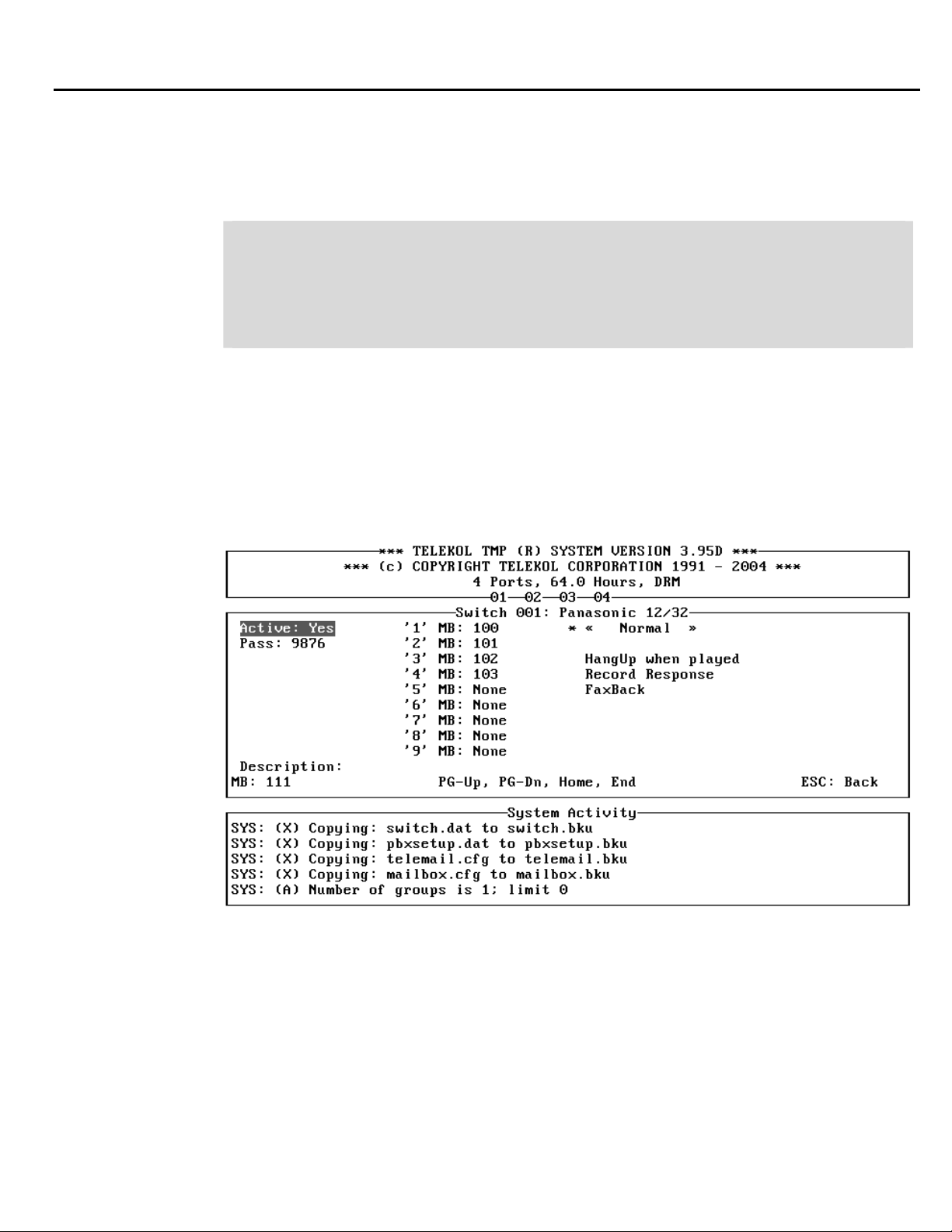
Setting Up Audiotext Mailboxes
Audiotext Mailboxes can be used as part of a fax on demand or ordering application, to provide
announcements to callers, or to present a series of options for routing incoming calls.
Example:
ABC Corporation wishes to have callers who enter “200” to be routed to a menu of options. The
menu will say, “For widget sales, press 1. For computer sales, press 2. For software sales, press
3.” The call will then be routed to the appropriate extension based upon what the caller chooses. If
the caller presses 1, she/he will be transferred to extension 110. If the caller presses 2, she/he will
be transferred to extension 111. If the caller presses 3, she/ he will be transferred to extension 112.
1. From the Main Menu, enter the Mailbox Setup/Editing screen by pressing [M].
2. Edit a new mailbox by entering [E] from the Mailbox Setup/Editing screen.
3. Enter the number of the mailbox that will be configured as the menu or audiotext mailbox. Using
the above application example, enter 200.
4. Move the highlight to «Audiotext» and press [ENTER]. The screen will display a message
stating that this process is irreversible and will remove all messages from this mailbox. Press [Y]
and then [ENTER].
5. The Audiotext screen will be displayed as shown below:
Section 2: Mailbox Setup
F
igure 2-6: Audiotext Screen — To access from the Main Menu press [M], [E], «Audiotext»,
[Y].
6. Enter the mailbox which callers will be transferred to when they press “1” in the ‘1’ MB field.
Using the application example, enter 110 in this field.
7. Repeat step 6 for any remaining digits. In our application example, enter 111 in the ‘2’ MB field
and 112 in the ‘3’ MB field.
8. Record the greeting for this Audiotext Box by calling into the TVM-2000 System. When the
welcome greeting plays, press [*] + [Mailbox Number]. Enter the mailbox’s access code when
prompted. The default access code is 9876. The system will immediately prompt for the
recording of a new greeting.
TVM-2000 Technical Reference Manual 37
Page 52

Section 2: Mailbox Setup
An Audiotext mailbox co
limit on the number of Au
uld lead to another Audiotext Box or to a regular extension. There is no
diotext levels in the system. Plan your Audiotext trees before
implementing them.
Before assigning audiotext f
dialog will appear
whether or not there are any messages and faxes outstanding.
unctionality to a mailbox, ensure that the mailbox is empty. The warning
38 TVM-2000 Technical Reference Manual
Page 53

Setting Up Q&A Mailboxes
The Question and Answer Audiotext mailbox allows the TVM-2000 to gather and process
information automatically.
Example:
An advertising company wishes to automate the process of the placement of magazine ads. The
questions that need to be answered are as follows:
1. Name & billing address of the company
2. Telephone number
3. Size of the ad
4. Number of publications to run the ad
5. Credit Card Type
6. Credit card number & expiration date
After the information is recorded and stored in the specified Q&A Mailbox, the advertising firm
wants the TVM-2000 to say, “Thank you for you order. If we experience any difficulties while
processing your order, we will contact you immediately. Please submit all relevant artwork to
ABC Advertising 1234 Main Street, Anytown, Massachusetts 01234.”
1. From the Main Menu, enter the Mailbox Editing screen by pressing [M].
2. Type [E] from the Mailbox Setup/Editing screen.
3. Enter the number of the mailbox that will be configured as the first question.
4. Move the highlight to «Audiotext» and press [ENTER].
5. Activate (put a “*” next to) the Record Response field.
6. Enter the number of the second question in the Next Mailbox field.
7. Enter the number of the mailbox in which all answers will be stored in the Store in MB field.
8. If the answer to this question is required, enter “1” in the Required field. If the answer is not
required, enter a “0” in the Required field.
9. Repeat steps 1 through 8 for the other questions.
10. For the “Thank you for your order...” follow steps 1 through 9 and then activate (put a “*” next
to) the Hang Up When Played field.
11. Record all of the questions by performing the following steps:
a. Call into the TVM-2000 and press [*]+[Mailbox Number].
b. When prompted, enter the access code. The default access code is 9876.
c. Follow the prompts to record each question.
Section 2: Mailbox Setup
TVM-2000 Technical Reference Manual 39
Page 54

40 TVM-2000 Technical Reference Manual
Page 55

Enabling Announcement Only
Announcement Only mailboxes are used to play informational messages. After playing the
information, callers are routed back to the Main Menu Part 1.
1. From the Main Screen, enter the Mailbox Setup/Editing screen by typing [M].
2. Type [E] from the Mailbox Setup/Editing screen.
3. Enter the number of the mailbox that will be used.
4. Set the Extension field to “None”.
5. Set the Max Msgs field to “0”
6. Record the personal greeting for this mailbox as any other mailbox greeting.
Note — You can dial an extension from an Announcement Only mailbox.
Section 3:
Using TVM-2000 Features
Fax On Demand Setup
Fax On Demand can be configured to allow callers to request faxes be sent to them automatically
Fax On Demand works in conjunction with Audiotext. To make faxes available to callers, they m
e faxed into thb
i
ma lbox.
1. From the main menu, enter the Mailbox Setup/Editing screen by pressing [M].
2. Type [E] from the Mailbox Setup/Editing screen.
3. Enter the number of the mailbox that will be used. Press [ENTER].
4. Highlight «Audiotext» and press [ENTER].
5. Activate (place a “*” next to) the FaxBack field.
6. Assign document numbers to the individual documents.
8. At the administrator side dial [9]+[0]. The TVM-2000 will prompt you to enter the document
number, ask you to confirm the number, then ask you to push the start button on your fax
machine. The voice mail will confirm the fax transmission and ask if you would like to add
additional documents. The document numbers are recorded in the ‘MB’ field on the Audiotext
Screen. Repeat until all documents have been entered.
9. If you want access to more than ten documents, you must organize your documents via audiotex
trees.
10. ey have
The audiotext trees can be organized in such a way to send callers back one menu after th
selected a document. To acco
One Selection
e TVM-2000 system and left like a message in the correctly identified Audiotext
field.
achine and acc7. Dial into your TVM-2000 from a local fax m
mplish this, return to the «Audiotext» menu and activate the FB
ess the system administrator’s side.
.
ust
t
TVM-2000 Technical Reference Manual 41
Page 56
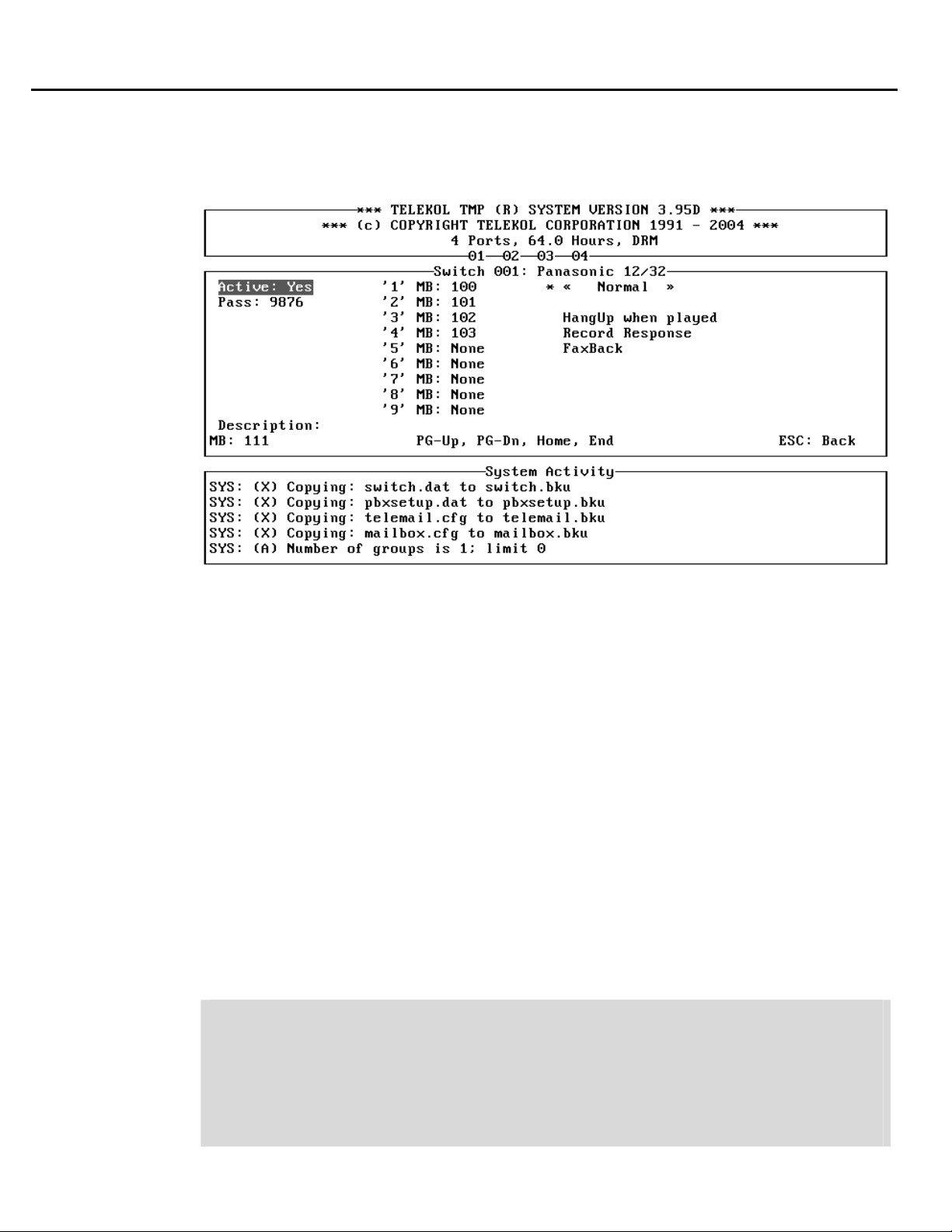
Section 3: Using TVM-2000 Features
To Set Up an Audiotext Mailbox
Audiotext Mailboxes play a series of options for routing incoming calls.
F
igure 3-1: Audiotext Screen — To access from the Main Menu, press [M], [E], mailbox #,
«
Audiotext».
1 Mailbox Setup/Editing screen by pressing [M].
. From the Main Menu, enter the
2.
Edit a new mailbox by entering [E] from the Mailbox Setup/Editing screen.
3 sing
. Enter the number of the mailbox that will be configured as the menu or audiotext mailbox. U
the above application example, enter 200.
4
. Enter the mailbox number that will be configured as the Menu or audiotext mailbox.
5.
If the mailbox is not active, press [ENTER].
6
. The screen will display a message stating that this process is irreversible and will remove all
messages from this mailbox. Press [Y] and then [ENTER].
7
. Access the «Audiotext» screen.
8 e mailbox that callers will reach when they press ‘1’ in the ‘1’ MB field.
. Enter the number of th
Using the application example, enter 110 in this field.
9
. Repeat step 8 for any remaining digits. In our application example, enter 111 in the ‘2’ MB field
and 112 in the ‘3’ MB field.
1
0. Record the greeting for this Audiotext Screen by calling into the TVM-2000 System. When the
welcome greeting plays, press [*] + [Mailb
prompted. The default access code is 9876. The system will immediately prompt for the
recording of a new greeting.
ox Number]. Enter the mailbox’s access code when
Example:
ABC Corporation wishes to have callers routed to a menu of options when the caller enters 200
for the sales department. The menu will say, “For widget sales, press 1. For computer sales, press
2. For software sales, press 3.” The call will then be routed to the appropriate extension based
upon what he/she chooses. If the caller presses 1, they will be transferred to extension 110. If the
caller presses 2, they will be transferred to extension 111. If the caller presses, 3, they will be
transferred to extension 112.
42 TVM-2000 Technical Reference Manual
Page 57

How An Audiotext Tree Works
Audiotext mailboxes enable a caller to quickly reach a more specific subset of mailboxes after each
menu.
Example:
A mortgage company programs the TVM-2000 to offer callers a set of single digit options after
playing the welcome message.
MAIN MENU: “Dial [1] for first and second mortgages rates. Dial [2] for answers to frequently
asked questions about mortgages. Dial [3] to apply for a new mortgage or to refinance your
cu nts and rrent mortgage. Dial [4] for existing account information. Dial [5] for delinquent accou
foreclosure abatement programs. Dial [0] or stay on the line to speak to a Customer Service
Representative.”
Option One is an Audiotext box that plays the following prompt after the announcement regarding
today’s rates:
MENU 1-1: “Dial [1] for answers to frequently asked questions on qualifying for mortgages. Dial
[2] to apply for a new mortgage or to refinance your current mortgage. Dial [0] or stay on the line
to speak to a Customer Service Representative.”
Option Two is another Audiotext box that plays the following options:
MENU 1-2: “For answers to questions on how to improve a bad credit record before applying for
a mortgage, dial [1]. For answers to questions on how the mortgage application and closing
process works, dial [2]. For answers to questions on how to pre-qualify for a mortgage, dial [3].
To learn about the types of mortgages available through us, dial [4]. To speak to a Customer
Service Representative, dial [0].”
Option Three is an ACD Group mailbox that consists of residential loan officers. The system
hunts through the extensions until an open extension is available. The caller is put in a holding
queue. The caller is given the option to hold or leave a message by pressing [1] at any time.
Option Four is a Q & A mailbox that asks the customer to provide account information prior to
sending the call through to another ACD group consisting of customer service representatives.
The caller is put in a holding queue. The caller is given the option to hold or leave a message by
pressing [1] at any time.
Option Five is another Q & A mailbox that asks the customer to provide account information, and
perhaps case numbers, prior to sending the call through to another ACD group consisting of
collection specialists. The caller is put in a holding queue. The caller in given the option to hold or
leave a message by pressing [1] at any time.
To set up audiotext mailboxes, See “ Setting Up Audiotext Mailboxes” on page 37. To set up Q&A
mailboxes, See “Setting Up Q&A Mailboxes” on page 39.
Section 3: Using TVM-2000 Features
TVM-2000 Technical Reference Manual 43
Page 58

Section 3: Using TVM-2000 Features
Enabling Message Forwarding
The Message Forwarding feature allows the administrator to specify an alternate mailbox to send
messages to if the mailbox owner does not retrieve messages within a specified time range.
1. From the Main Screen, enter the Mailbox Setup/Editing screen by typing [M].
2. Type [E] from the Mailbox Setup/Editing
3. Enter the number of the mailbox that will be used.
4. Enter the number of the mailbox to which messages should be forwarded in the Msg Fwd To
field.
Set the number of days to wait before forwarding a new message in the Msg Fwd Days Field.
5.
(Marking this field “0” causes the TVM-2000 to forward this message immediately.)
. Record the personal greeting for this mailbox as you would any other mailbox greeting. 6
screen.
44 TVM-2000 Technical Reference Manual
Page 59
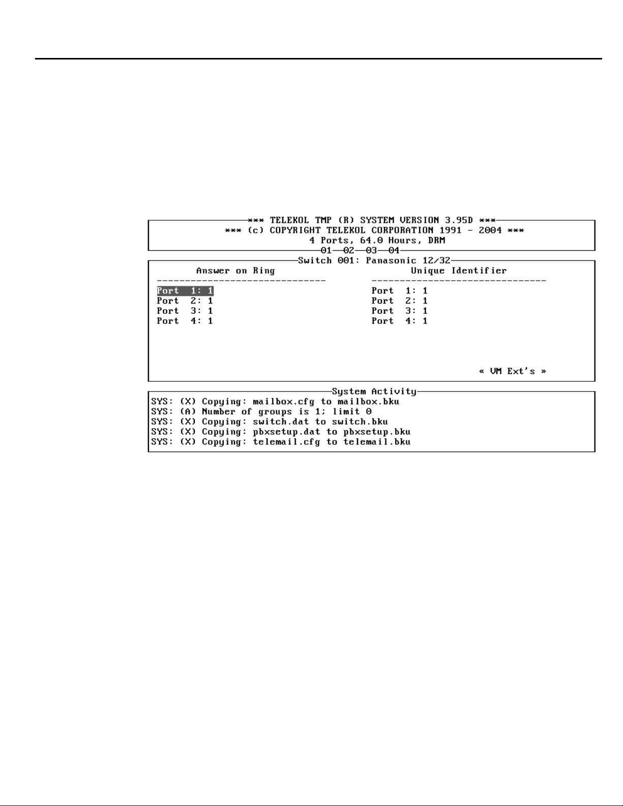
Enabling Multi-Tenant Applications
Multi-tenantin
ithout sacrificing any of the features available to single company users. Enabling Multi-tenanting
w
can be done either by using Line ID Mapping or Port
Using Port Specific Options
sin pecific Options involves assigning unique identifiers for each voice mail port. This is
g Port SU
done via the Port Specific Options screen, shown below:
g allows two companies to share the same telephone switch and TVM-2000 system,
Section 3: Using TVM-2000 Features
Specific Options.
Figure 3-2: Port Specific Options Screen — To access from the Main Menu, press [P].
1. c Ac ess the [P]ort Specific Options screen.
2.
Assign a unique identifier for each port.
3. ue identifier.
Call into each port and record a separate greeting message for each uniq
4.
up Operator Mailboxes for Multi-tenant applications.See the instructions below on setting
TVM-2000 Technical Reference Manual 45
Page 60
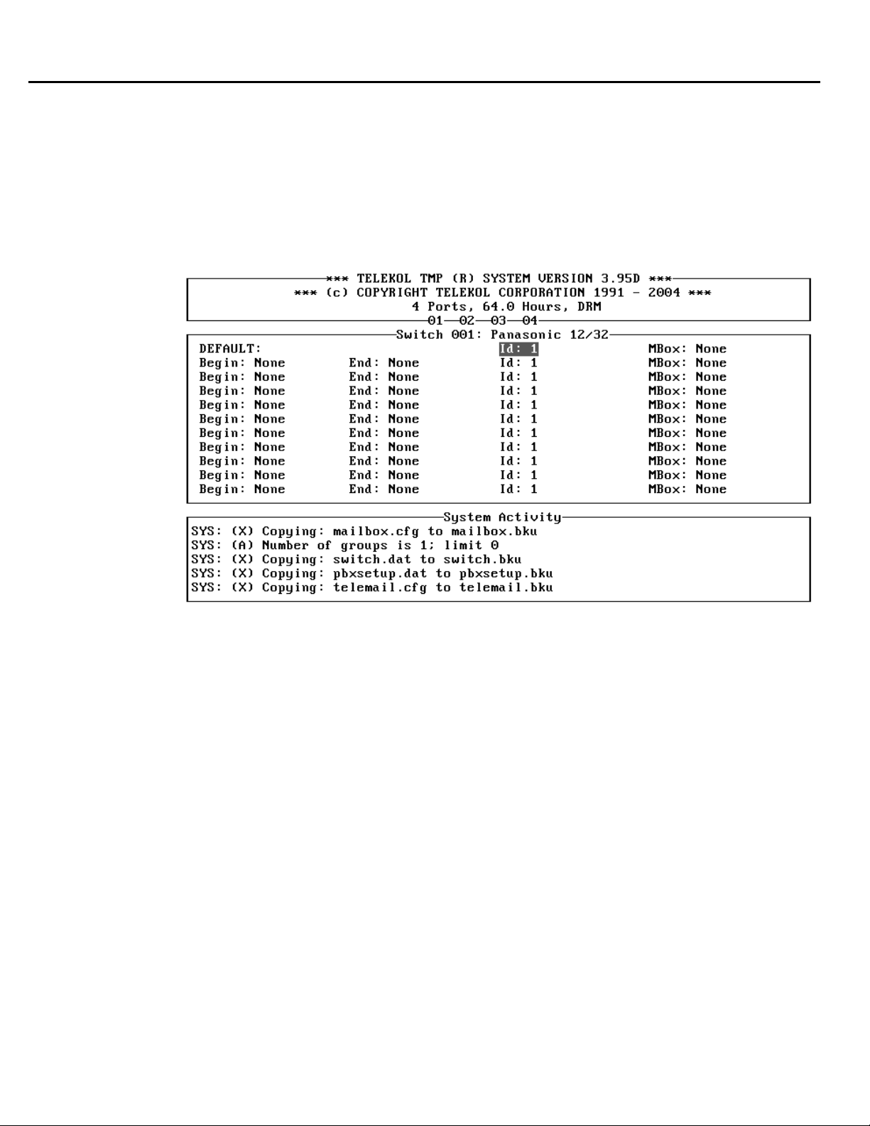
Section 3: Using TVM-2000 Features
Using Line ID Mapping
Using Line ID Mapping requires telephone switches capable of sending In-band Trunk ID
information
To enable Line ID Mapping, follow the steps below:
1. From the Main Menu, pre
Screen.
ss [A]dvanced, then [L]ine ID Mapping to get to the Line ID Mapping
Figure 3-3: Line ID Mapping Screen — To access from the Main Menu, press [A], [L].
2. Enter the beginning and ending Trunk ID number for each company.
3. Record the main greetings (repeat for each company):
a. Call in one trunk for Company ABC.
b. Access the administrator m
c. Enter the administration area and Record Greetings section; [9][3]
d. Record the desired greeting(s).
4. Set up the operator DAY and NIGHT general delivery mailboxes for each company:
Telekol recommends against using night and day general delivery mailbox numbers of 0. If,
for some reason, it is necessary to use a general delivery mailbox number of 0, please refer to
“Setting Up Multi-tenant and Multilingual Operator (General Delivery) Mailboxes” below for
a listing of warnings and special instructions that go along with configuring your multi-tenant
system in this manner.
a. Access the [O]peration screen from the main menu.
b. Check the day general delivery mailbox number for Company ABC. The number shown plus
the company ID# in the Line ID mapping section will be the operator mailbox (during the
ay) for Company ABC. Example: If the day general delivery mailbox for Company ABC is
200 and the ID# is 3, then the operator mailbox (during the day) would be 203. Note:
Companies with a line ID# of “1” are an exception to this rule. If the line ID# is “1”, the
operator mailbox number is the same as the day general delivery mailbox number.
ailbox; [*][999].
46 TVM-2000 Technical Reference Manual
Page 61

Section 3: Using TVM-2000 Features
Setting Up Multi-tenant & Multilingual Operator (General Delivery)
Mailboxes
When a call comes into the multi-tenant or multilingual system, the operator mailbox number is
calculated according to the tenant number or language number. Tenant number or language number
referred to as “ID” below. is
fo e “Operator by ID” (if configuring Multi-tenant) oBe re beginning this procedure, make sur
“Operator by Language” (if configuring multilingual) on the [A]dvanced, [M]ore screen is set to
e
“Y s”.
The operator mailbox number for each incoming call should calculated according to the following
e
rul s:
1. If a tenant or language has an ID of 1, the Operator (General Delivery) mailbox number is the
number entered in the Day or Night General Delivery MB field.
2. For all other ID’s, the Operator (General Delivery) mailbox number is the number entered in the
Day or Night General Delivery MB
Example 1:
A Four-port system is configured for four tenants. The “Multi-tenant by port” application is use
The Port unique identifiers are “1” for port 1, “1” for port 2, “2” for port 3, and “2” for port
Day General Delivery MB is 100 and the Night General Delivery MB is 300.
PORT ID DAY OPERATOR NIGHT OPERATOR
1 1 100 300
2 1 100 300
3 2 102 302
4 2 102 302
The TVM-2000 will hang up on the callers who are routed to Operator (General Delivery)
Mailboxes that do not exist. (The nonexistent operator mailbox is printed in the system activity
window and in the log file.)
field plus the ID number.
4. The
r
d.
TVM-2000 Technical Reference Manual 47
Page 62

Section 3: Using TVM-2000 Features
Creating Call Screening within the Voice Mail
This feature enables switches that do not support Call Screening to use the TVM-2000’s hardw
and software to set up Call Screening without the help
ith all switches. To check whether or not TVM-2000 can emulate call screening with a particular
w
switch, see “Loading Switch Defaults” on page 16.
1.
Access the [M]ore Switch Configuration Menu by pressing [A], [M] from the Main Menu.
2.
Enter “Yes” in the Alt. Spkrphn field.
3. Refer to the reference manual that came with the switch to determine the specific digits to enter
in Put on Hold and Pick up
Screening to work properly.
4. For each individual mailbox, activate (put a “*” next to) the Speakerphone field in the «Mailbo
Attr.» screen.
nce these parameters are enabled/have values set, the Voice Mail systems first refers to the switch
O
for Call Screening, and upon not finding it at the switch level, returns to the Voice Mail system,
accessing the Alt. Spkrphn settings.
The caller dials the mailbox owner’s extension, and the TVM-2000 asks the caller to speak his or he
name. The TVM-2000 then dials the extension number. If the call connects, the TVM-20
ceiver if she/he wants to take a call from [caller’s recorded name>, prompting to press [1] to
re
accept. The receiver hangs up the phone, and the TVM-2000 releases the caller back to the
extension. Hanging up without pressing [1] returns the call to Voice Mail message prompts.
Hold fields. These fields must have values entered for Call
of the switch. This approach does not work
are
x
r
00 asks the
48 TVM-2000 Technical Reference Manual
Page 63

Creating Paging within the Voice Mail
Many of the switches that do not have the “Meet-Me Page” feature can still use TVM-2000’s
hardware and software to offer paging functionality.
1. In the [M]ore Switch Configuration Menu, change the Alt. Page Parameter to “Yes.”
2. Refer to the switch’s Integration Note (See the Switch Integration Manual ) and the reference
manual that came with the switch to determine the specific digits to enter in Put on Hold and
Pick up Hold fields. These fields must have values entered in order for Paging to work.
3. For each individual mailbox, activate (put a “*” next to) the Page Ok or Page Always field in
the «Mailbox Attr.» screen.
Once these parameters are enabled/have values set, the Voice Mail system first refers to the switch
for Paging, and upon not finding it at the switch level, returns to the Voice Mail system, accessing
the Alt. Page settings.
To use this method for paging with Page Ok enabled, the caller dials the mailbox owner’s extension,
and fails to connect (no answer). The Voice Mail offers the caller the option of entering [3] to page.
Upon confirmation from the caller, the Voice Mail dials the paging sequence. The Voice Mail then
plays the mailbox owner’s pre-recorded name or extension number over the public address system,
announcing that the extension has a call, and that it is being transferred to an extension.
When Page Always is enabled, the caller does not get a series of prompts with paging as one of the
options. Instead, the caller is put on hold and the Voice Mail immediately dials the paging sequence.
Section 3: Using TVM-2000 Features
TVM-2000 Technical Reference Manual 49
Page 64

50 TVM-2000 Technical Reference Manual
Page 65

Section 4:
Optio
nal Equipment Installation & Configuration
The TVM-2000 can be customized with a variety of optional features.
The Fax Module allows the TVM-2000 to become a complete fax-processing platform. Each
mailbox owner can receive, view, print or delete faxes through their existing voice mailbox or
through a separate fax mailbox. Fax mail can be sent to any fax machine for printing at any time of
the day. The Fax Module can also be used to print to any printer connected to the computer. The Fax
odule also allows voice mail messages to be attached to faxes. M
The Hospitality Module can be used by administrators in the Hotel/Motel industry to create guest
mailboxes, wake up calls, and a host of other features.
PMS Module automatically administers TVM-2000 mailboxes by integrating with existing
The
Property Management Systems.
The Multi
language
T 00 is also ava ith
he TVM-20 ilable with an SMDI Module that allows the TVM-2000 to integrate w
d ches using SMD
igital swit I. See your Telekol Authorized Dealer for details.
lingual Software Module allows callers to the TVM-2000 to choose from a variety of
s.
TVM-2000 Technical Reference Manual 51
Page 66
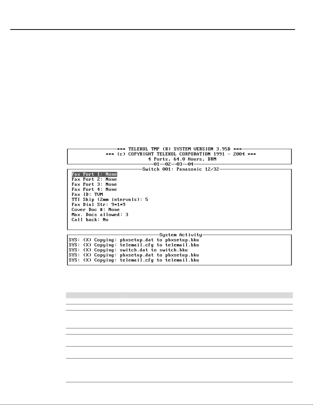
Section 4: Optional Equipment Installation & Configuration
Fax Module
The optional Fax Module allows each mailbox owner to receive, print and delete faxes through their
existing voice mailbox or through separate fax mailboxes. Fax mail can be sent to any fax machine
or local printers. The TVM-2000 system handles fax mail an d voice mail in the same fashion. The
ax Module also allows voice mail messages to be attached to faxes.
F
The Fax Module can be ordered pre-installed with new TVM-2000 units, or added as an upgra
xisting voice mail products from Telekol. If purchased as an Upgrade, the Fax module is delivered
e
n 3.5" diskette along with Upgrade instructions. Upgrading existing systems to include the Fax
o
Module requires that the existing system first be upgraded to TVM-2000 Version 3.7.
Configuring the Fax Module
Configuration of the Fax Module requires setting up the extension numbers to which fax ports are
connected.
de to
Figure 4-1: Fax Configuration Screen — To access from the Main Menu, press [C], «Fax
Config».
FIELD DESCRIPTION
Fax Port # Indicates the extension number dedicated to that particular fax port.
Fax ID Text ID to print at the top of the pages sent.
TTI Skip When the fax document is originally entered into the TVM-2000
mailbox, the Fax ID header is included. This enabling just the new one
to appear when the document is faxed from the system.
Fax Dial String Indicates default string sequence for faxing documents.
Cover Doc # Multiple cover pages can be assigned numbers and then a default cover
page can be established in this field.
Max. Docs Allowed Indicates the maximum number of documents that can be attached to a
single fax.
Call back If set to No, does not call phones back to fax. When set to Yes, the
caller is prompted to enter the receiving fax number and hang up. The
TVM-2000 then calls the entered fax number and faxes the requested
documents.
52 TVM-2000 Technical Reference Manual
Page 67

Section 4: Optional Equipment Installation & Configuration
Overflow to Fax Mailbox
The TVM-2000’s Overflow to Fax Mailbox feature allows faxes to be stored in a mailbox when the
local fax machine is busy or down for maintenance. To configure the Overflow to Fax Mailbox
feature, follow the steps below:
1. From the Main Menu ch
2. Access the [E]dit Mailboxes screen.
4. In the Mailbox Editing Screen
Ext: field.
5. Access the «Mailbox Attr .» screen.
6. Select the NoCallProgress field and make sure there is no asterisk (*) next to it. If there is, press
[ENTER] to remove it.
7. Activate (put a “*” next to) the FaxOnly field.
oose the [M]ailbox Setup/Editing option.
u have assigned to the Fax Mailbox. 3. Enter the mailbox number yo
enter the extension number to which the fax is connected in the
TVM-2000 Technical Reference Manual 53
Page 68
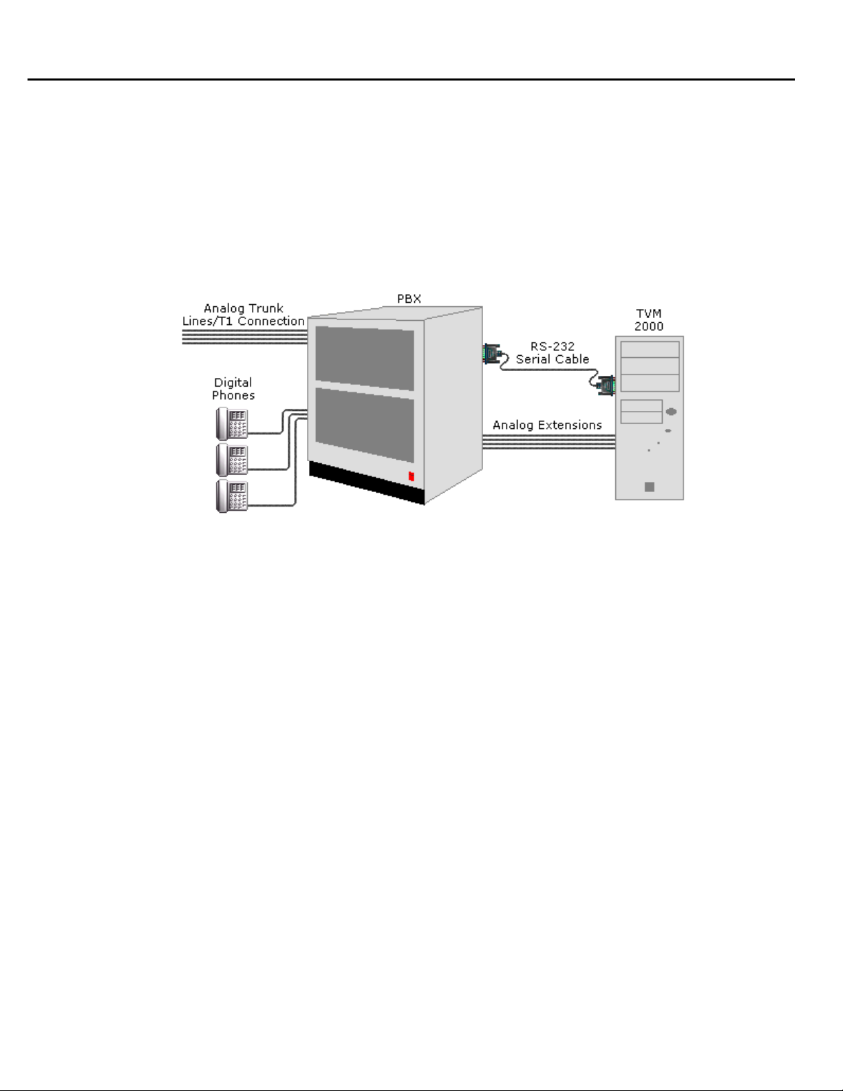
Section 4: Optional Equipment Installation & Configuration
SMDI Integra
tions
The Digital Options submenu and screens allow the TVM-2000 to integrate with PBXs that have the
capability of sending integration to the Voice Mail via out of band serial connections. Follow the
steps below to set up an SMD
SMDI enabled TVM-2000 systems can only have ONE fax port. This section is common to all
SMDI integrations. For switch-specific SMDI notes refer to the Switch Integration Manual.
I switch with the TVM-2000.
Figure 4-2: SMDI integration with the TVM-2000 Voice Mail server
. Attach 1
unit. (See “Connecting to the Telephone System” on page 11).
2. Plug the switch into the available voice mail ports on the back of the TVM-2000 unit.
. Load the switch default listed in the Switch Integration Manual for your SMDI switch. 3
the switch’s serial feed to Serial Port #2 on the back of the SMDI enabled TVM-2000
54 TVM-2000 Technical Reference Manual
Page 69
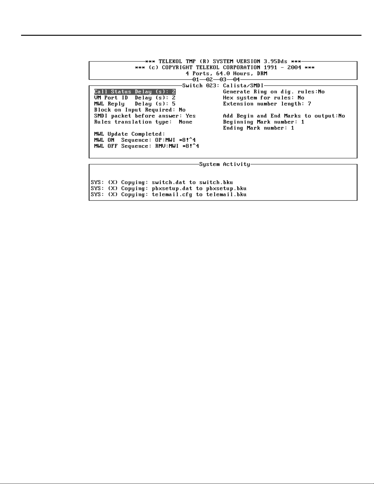
Section 4: Optional Equipment Installation & Configuration
4. Access the General Configuration screen.
Figure 4-3: General Conf
ig Screen — To access from the Main Menu, press [A], [M], «Digital
Options», «General Config»
5. Set COM Port to “2”.
. Match the Baud Rate, Data Bits, Parity, and Stop Bits settings to those on y6
7. Reboot the TVM-2000 unit.
our SMDI switch.
TVM-2000 Technical Reference Manual 55
Page 70
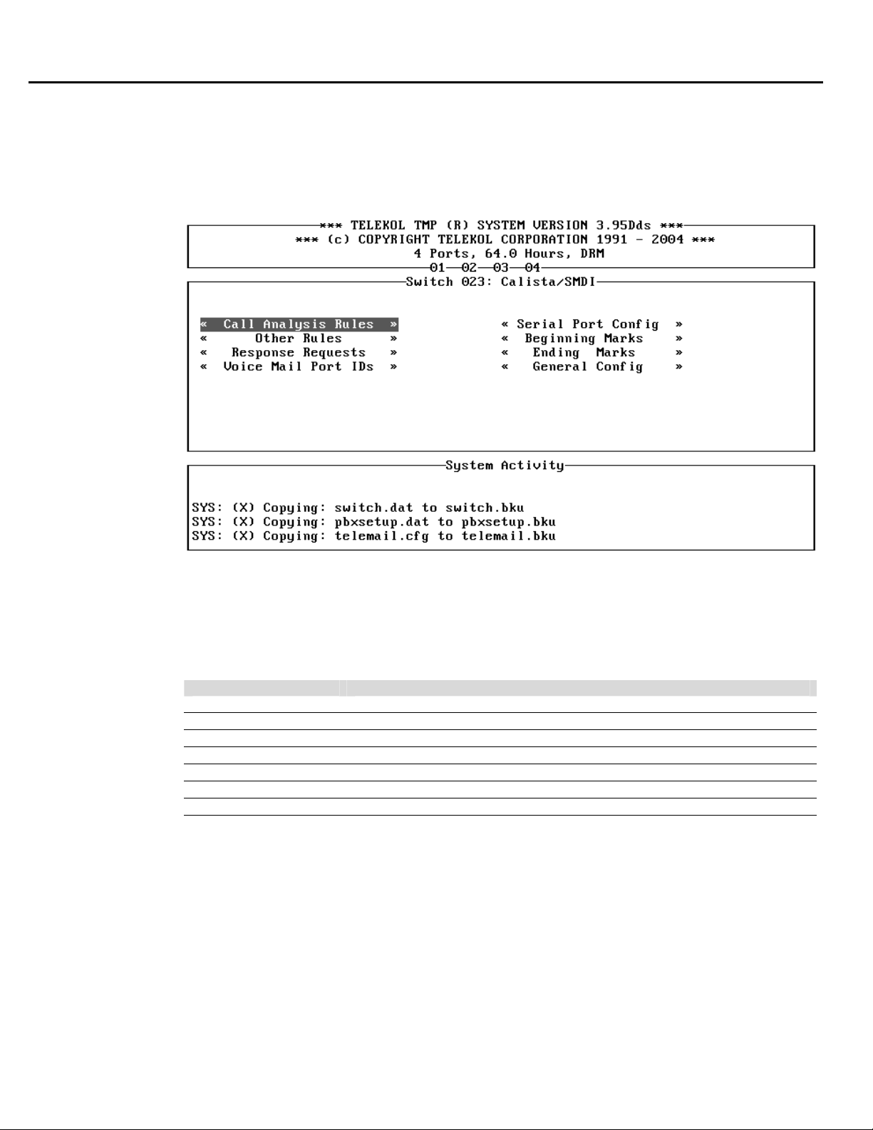
Section 4: Optional Equipment Installation & Configuration
Advanced SMDI Setup
The screens listed in the Advanced setup sections contain values that are automatically loaded with
the SMDI switch defaults. Most of these fields should not r equire changes during normal setup and
peration. Before changing any of the fields listed in the steps below, contact Telekol Technical
o
Support at 1-800-797-0123.
Figure 4-4: Digital Options screen — To access from the Main Menu, enter [A], [M], «Digital
Options»
The TVM-2000 receives information from SMDI capable switches for each incoming call and
continuously scans the serial port for call information such as disconnect signals and dialed digits.
FIELD DESCRIPTION
Call Analysis Rules Accesses the Call Analysis screen.
Other Rules Accesses the Other Rules screen
Voice Mail Port IDs Accesses the Voice Mail Port IDs screen
Serial Port Config Accesses the Serial Port Config Screen
Beginning Marks Accesses the Beginning Marks Screen
Ending Marks Accesses the Ending Marks Screen
General Config Accesses the General Config Screen
56 TVM-2000 Technical Reference Manual
Page 71

Section 4: Optional Equipment Installation & Configuration
Processing Rules in SMDI
The TVM-2000 is able to interpret serial rules specified in two kinds of formats, as ASCII codes
as Hexadecimal co
onfiguration screen (See “General Config Screen” on page 55.)
C
des, depending on the setting for the Hex System for Rules field on the General
Each rule is a logical representation of a string of characters that the VM receives from the PBX. All
variable characters such as calling extension number or trunk number, should be substituted with
special ‘%$’ sequences, where:
VARIABLE DESCRIPTION
%F Forwarding from extension number
%E Calling extension number
%G Calling trunk group
%T Calling trunk number
%D Calling DID port
%A Caller ID
%V Voice Mail ID of port that the incoming call information is for
%X Unused or insignificant number
%I Dialed digits (may include ‘*’ and ‘#’)
%Q Extension number ML operation is being performed for
? Any character
* Any number of any characters
For example, if the PBX sends the sequence ‘02,EVVV,EXXX,EYYY’ when an internal call is
forwarded upon busy condition from extension YYY to VM ID of VVV and the original caller is
XXX, one of the «Fwd Busy
Int.» rules should look like ‘02,E%V,E%E,E%F’.
If rules are not delineated by commas, the width of
i ys: Throug tween
n one of two wa h the “Extension Number Length” field or by adding the width be
each field needs to be specified. This can be done
the “%” and variable. (%2F would denote a Forwarding Extension number that was two digits.)
Example:
A rule is set as “8543%F”.
If “Hex System for Rules ions ” is set to “No”, then all of the rules entered in the SMDI configurat
screen are taken as ASCII al) of codes. Thus the TVM-2000 will look for the ASCII values (decim
8543 (in other words, “56 52 51 50” coming through the serial port.
If “Hex System for Rules ” is set to “Yes”, then all of the rules entered in the SMDI configurations
screen are taken as Hexadecimal codes. Thus, the TVM-2000 will look for the Hexadecimal code
(Hex 85 and Hex 43 or 0x85 and 0x43) coming through the serial port.
Sequences sent FROM th y the e TVM-2000 to the PBX (Outgoing Rules) are not affected b
setting in the “Hex System for Rules” field. If Outgoing Rules are not ASCII sequences, they
should be proceeded by a “^” and should be three digits long. In other words, to send the decimal
number 45 to the switch, 0 should send the sequence “^045”. the TVM-200
If the TVM-2000 uses a sequence of characters to determine the beginning and ending of all
incoming sequences, thes Marks screen. (See e should be configured in the Beginning and Ending
“Beginning Marks Screen” on page 62).
or
TVM-2000 Technical Reference Manual 57
Page 72
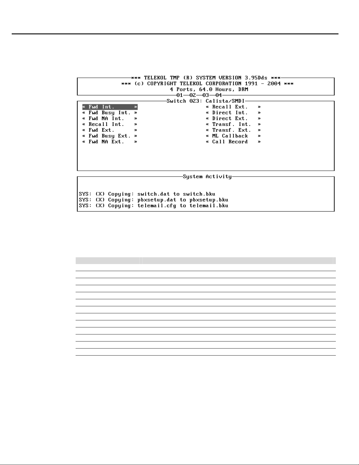
Section 4: Optional Equipment Installation & Configuration
Call Analysis Rules screen
The Call Analysis Rules screen allows the administrator to configure how the TVM-2000 handles
information received about incoming calls from the PBX.
Figure 4-5: Call Analysis Rules Screen — To access from the Main Menu, press [A], [M],
«Digital Options», «Call Analysis Rules».
The sets of rules that each submenu represents is explained below:
SCREEN DESCRIPTION
«Fwd Int.» Internal Call Forwarded to VM on All Calls or unknown condition
«Fwd Busy Int.» Internal call forwarded to VM on busy condition
«Fwd NA Int.» Internal call forwarded to VM on No Answer condition
«Recall Int.» Internal unanswered call recalls to transferring VM port
«Fwd Ext.» External call forwarded to VM on All Calls or unknown condition
«Fwd Busy Ext.» External call forwarded to VM on busy condition
«Fwd NA Ext.» External call forwarded to VM on No Answer condition
«Recall Ext.» External unanswered call recalls to transferring VM port
«Direct Int.» Direct internal call to VM port
«Direct Ext.» Direct external call to VM port
«Transfer Int.» Internal call transferred to VM
«Transfer Ext.» External call transferred to VM
«ML Callback» Call to VM by pressing ‘Message’ (‘Msg’) button on digital keysets
58 TVM-2000 Technical Reference Manual
Page 73
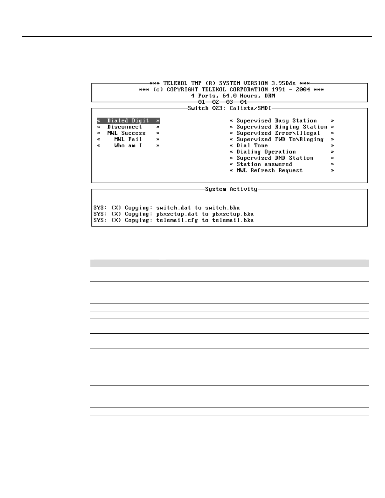
Section 4: Optional Equipment Installation & Configuration
Other Rules Screen
The Other Rules screen serves the same function as the Call Analysis Rules screen does for the
Analog switches.
Figure 4-6: Other Rules Screen — To access from the Main Menu, press [A], [M], «Digital
Options», «Other Rules».
SCREEN DESCRIPTION
«Dialed Digit» Digits dialed on a digital set that doesn’t provide in-bound DTMF
signaling.
«Disconnect» Sequence sent to Voice Mail upon caller being connected to VM port
has hung up.
«Who am I» Information about the extension number the VM port is connected to.
«MWL Success» ML operation success acknowledgment sequences.
«MWL Fail» ML operation failure acknowledgment sequences.
«Supervised Busy
Station»
«Supervised Ringing
Station»
«Supervised
Error/Illegal»
«Supervised FWD To/
Ringing»
«Dial Tone» Sequence: “Voice Mail is off-hook and receiving dial tone”.
«Dialing Operation» Voice Mail is receiving this sequence during any dialing operation.
«Supervised DND
Station»
«Station answered» Sequence: “Station is talking/interacting with Voice Mail”.
«MWL Refresh
Request»
Sequence: “Voice Mail tried to call Station, but Station was busy”.
Sequence: “Voice Mail has called Station which is ringing”.
Sequence: “Voice Mail did an operation which resulted in error signal”.
Sequence: “Voice Mail has called Station (A), but has been forwarded
to Station (B), which is ringing”.
Sequence: “Voice Mail tried to call Station, but Station has Do-NotDisturb set.”
Sends request to VM to turn on all MSG lights that should be on. The
VM turns on the lights at the next notification cycle.
TVM-2000 Technical Reference Manual 59
Page 74
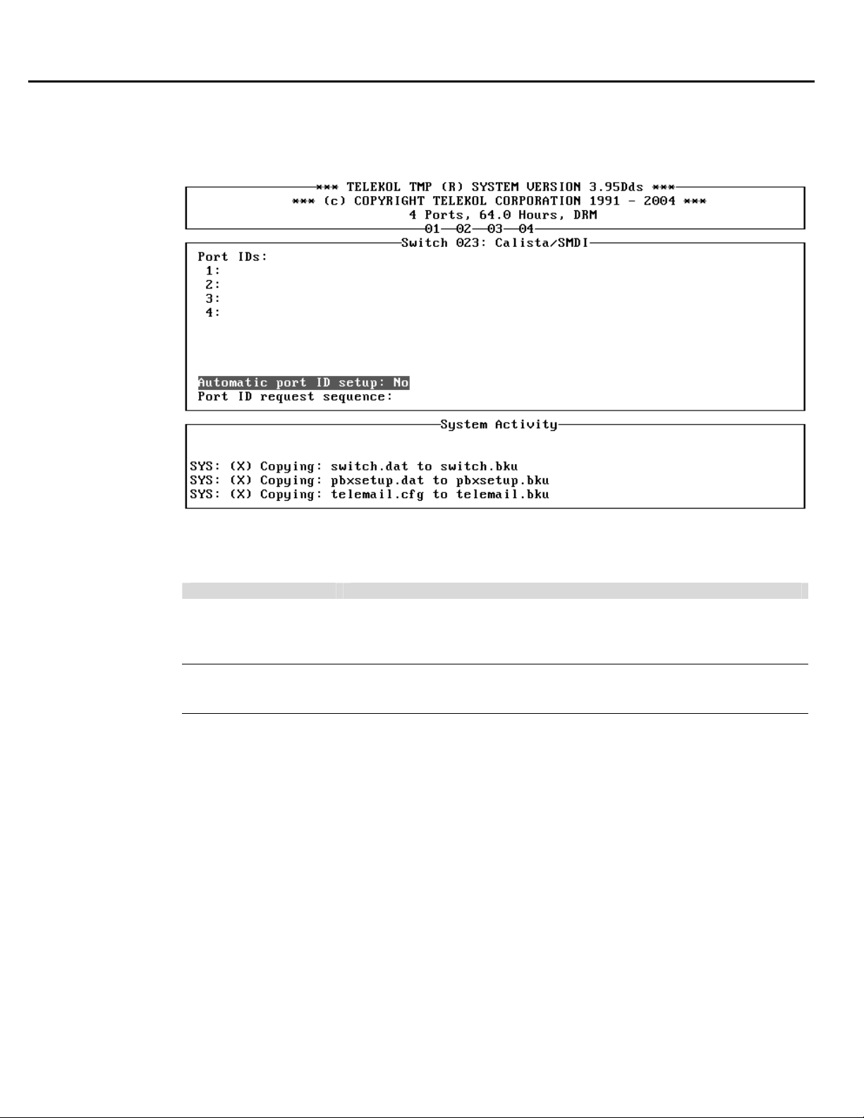
Section 4: Optional Equipment Installation & Configuration
Voice Mail Port IDs Screen
The Voice Mail Port IDs screen allows configuration of each Port ID. On this screen, the Voice M
ID is the port for the incoming call information. The ID is usually the same as the extension number.
ail
Figure 4-7: Voice Mail Port ID screen — To access from the Main Menu, press [A], [M],
«Digital Options», «Voice Mail Port ID».
FIELD DESCRIPTION
Automatic Port ID
Setup
Port ID Request
Sequence
If set to “Yes”, allows the automatic recognition of the VM extension.
The process of automatic VM extension configuration will start if the
Port ID request sequence is a non-blank string and at least one of the
Voice Mail IDs is not specified.
Allows the system administrator to enter the sequence of digits that the
VM port has to dial in order to receive its extension number. String may
contain Control Codes.
If automatic VM extension configuration is not supported by the PBX or if it fails, the system
administrator must specify the extension for each existing VM port in items 1: through 24:
respectively. If your system has less than 24 ports (as in the example above), menu items for nonexisting VM ports will not appear.
60 TVM-2000 Technical Reference Manual
Page 75
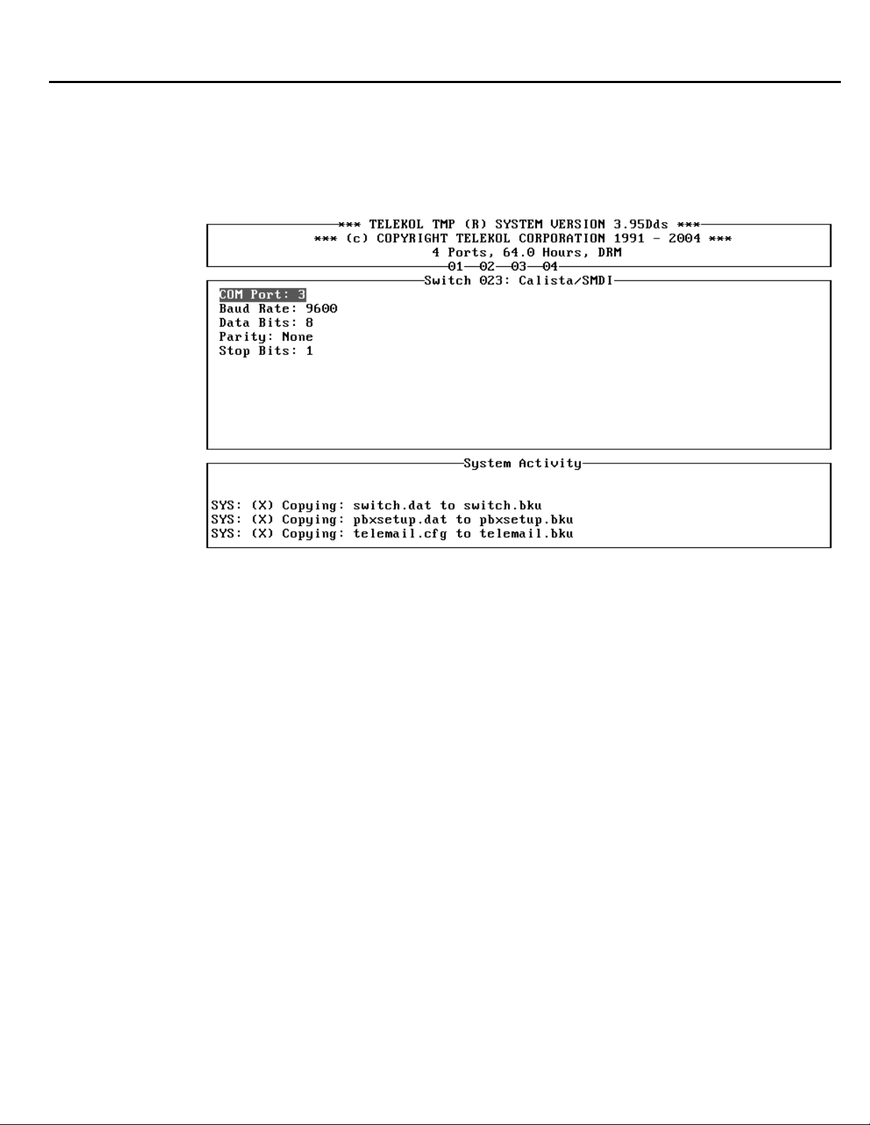
Section 4: Optional Equipment Installation & Configuration
Serial Port Configuration Screen
The Serial Port Configuration screen allows the system administrator to match parameters suc
COM port number, baud rate, parity, and numbers of stop and data bits with their respective PBX
settings. Whenever any of these parameters are changed, the TVM-2000 offers to reboot itself in
order for these changes to tak
e effect.
h as
’s
Figure 4-8: Serial Port Configuration Screen — To access from the Main Menu, press [A], [M]
«Digital Options», «Serial Po, rt Config».
TVM-2000 Technical Reference Manual 61
Page 76
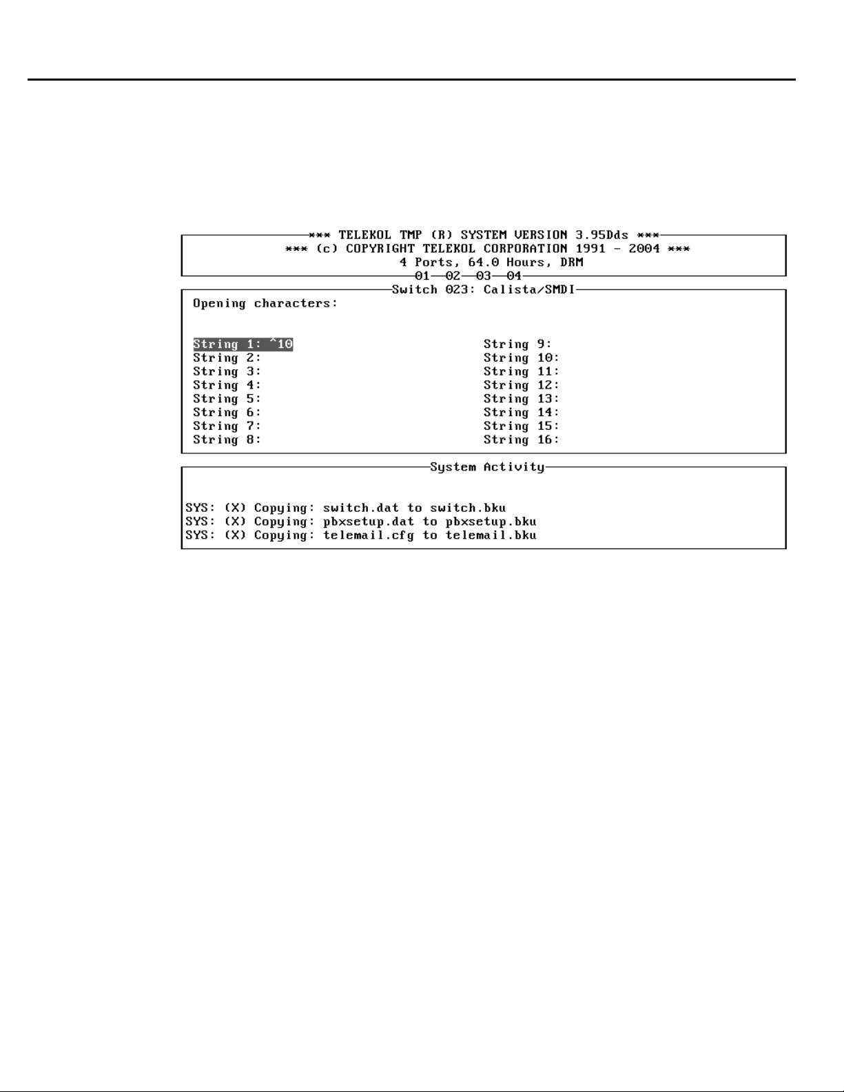
Section 4: Optional Equipment Installation & Configuration
Beginn
he Beginning Marks
T
represent the begin
in the beginning mark has an ASCII code less than 32 (20H) it can be substituted by the ‘^’ character
followed by its ASCII code, specified right away, or in a combination of formats. The characters ‘^^’
represent the ‘^’ character itself.
ing Marks Screen
screen allows the system administrator to enter one to sixteen strings that
ning of the meaningful sequence of characters in the serial stream. If a character
Figure 4-9: Beginning Marks Screen — To access from the Main Menu, press [A], [M],
«Digital Options», «Beginning Marks».
62 TVM-2000 Technical Reference Manual
Page 77
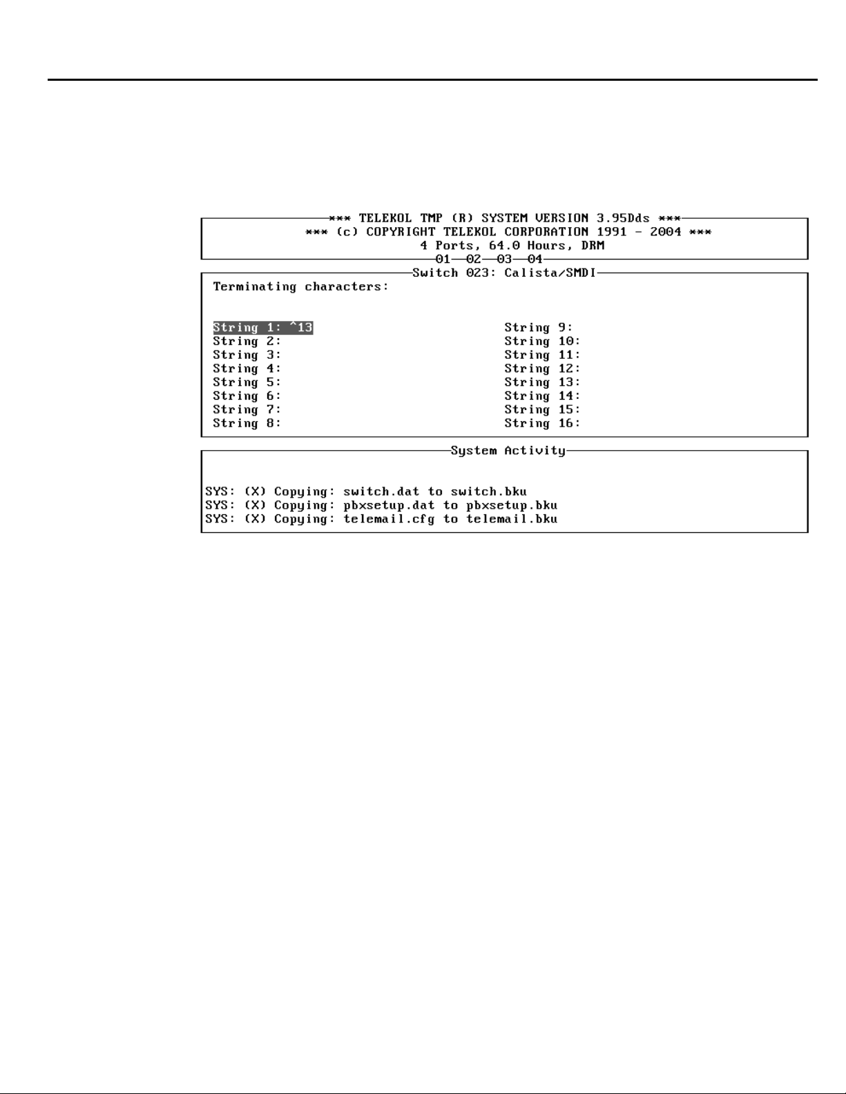
Section 4: Optional Equipment Installation & Configuration
Ending Marks Screen
The Ending Marks screen allows the system administrator to enter one to sixteen strings that
represent the end of the meaningful sequence of characters in the serial stream. Characters with
SCII codes less than 32 (20) are treated as they are in the beginning marks screen (see “Beginning
A
a e 62).
M rks Screen” on pag
Figure 4-10: Ending Marks screen — To access from the Main Menu, press [A], [M], «Digital
Options», «Ending Marks»
Note: All beginning and ending marks must use the ^ character for non-ascii data. The hex system
for rules has no effect on this table.
he extension number in MWL (Message Waiting Light) related sequences should be represented
T
by ‘*8’. For example, if the MWL On sequence for ext. 21 is ‘£21¥’, it will be set i
s ‘^156*8^157’.
a
n the TVM-2000
TVM-2000 Technical Reference Manual 63
Page 78
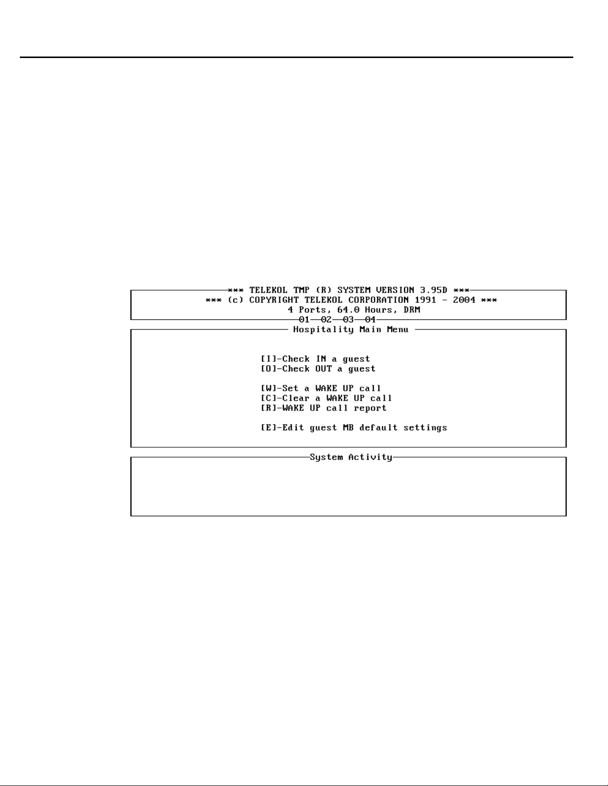
Section 4: Optional Equipment Installation & Configuration
Hospitality Mo
dule
Installation
purchased as part of a new TVM-2000 unit, the Hospitality Module is factory installed and tested.
If
If purchased as a field upgrade, the Hospitality Module is delivered on a 3.5" diskette for use only
for the unit with the serial number for w
lephone switch with Auto Login capabilities. To start the installation process, insert the diskette
te
into the a: drive on your voice mail unit, and select [U]tilities, [U]pgrade TVM System from the
Main Menu.
When the installation is complete, the unit will reboot and the Hospitality Menu will display
automatically.
If access to the system administrator menus is required, press [SHIFT] + [TAB] and enter the
administ
rator’s access code. The default code is [9876].
hich it was purchased. The Hospitality Option requires a
Figure 4-11: Hospitality Main Menu — This menu is the default Main Menu when the
Hospitality option is installed.
64 TVM-2000 Technical Reference Manual
Page 79
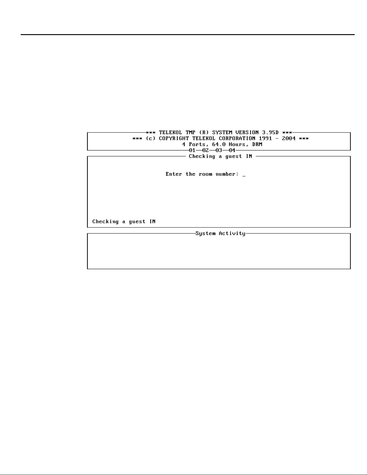
Section 4: Optional Equipment Installation & Configuration
Front Desk Operations
The Hospitality module was designed for use by front desk operators in hotels, motels or other
ospitality businesses. The day-to-day operation has two options:
h
• Check in a guest
• Check out a guest
Check in a Guest
To check in a guest press [I] from the Hospitality Main Menu, followed b
s
tsy em validates the room number to ensure that you are checking in to an unoccupied mailbox.
y the room number. The
Figure 4-12: Check In a Guest
Upon successful completion, the guest has an active mailbox at his or her disposal.
TVM-2000 Technical Reference Manual 65
Page 80
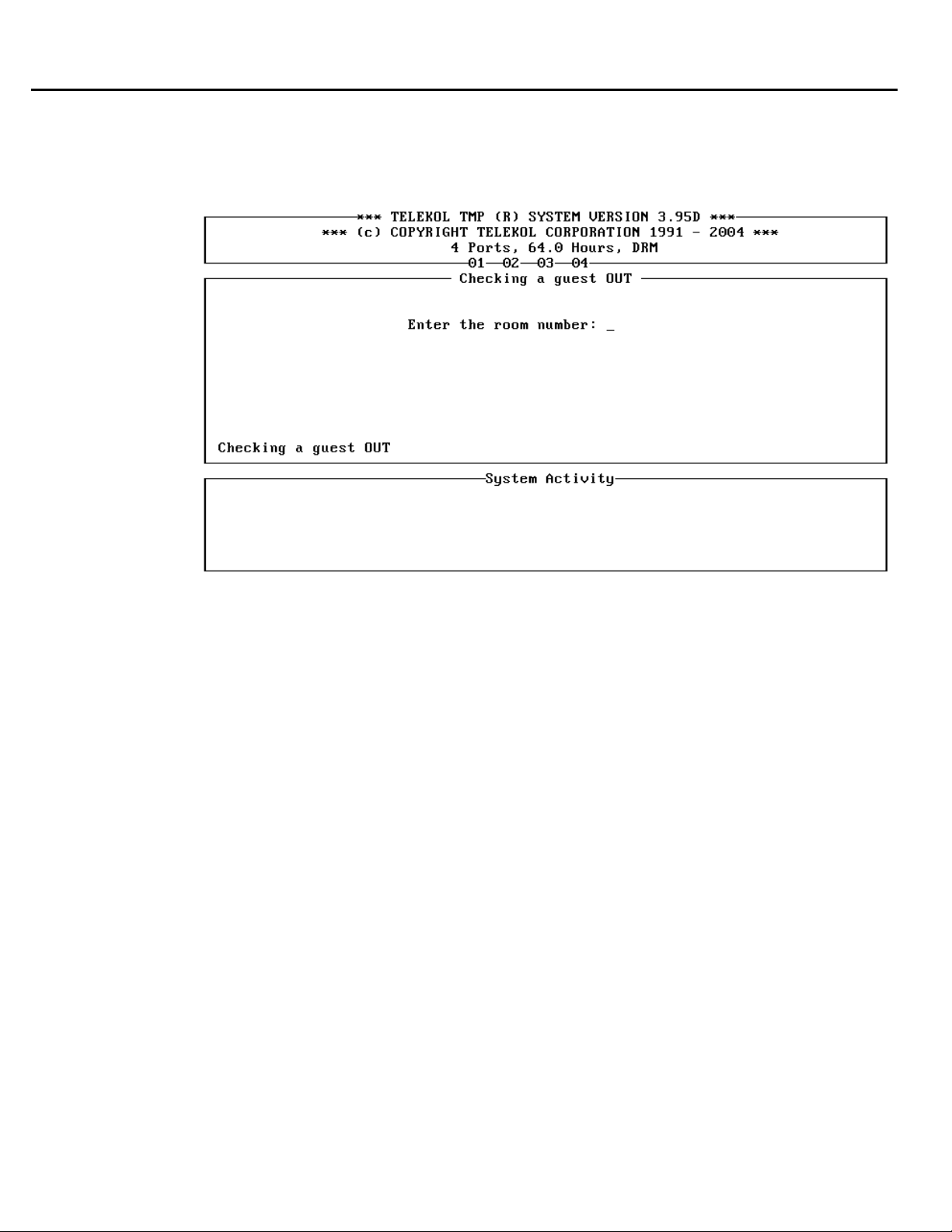
Section 4: Optional Equipment Installation & Configuration
Check out a Guest
To check out a guest, press [O] from the Hospitality Main Menu, followed by the room number of
the guest. The system checks to verify that this is an active guest mailbox, and checks for messages
n the mailbox.
i
Figure 4-13: Check Out Guest Menu
If the operator confirms the check out when new messages are still in the mailbox, these message
will be erased irreversibly!
If there are new messages in the guest’s mailbox, a confirmation dialog is displayed. The number of
new messages and faxes is highlighted. If the guest wishes to listen to these messages before the
completion of the check out, he or she may do so from either a house phone, or the guest’s roo
fter positive verification and the cA
heck out is completed, all existing messages and greetings are
m.
deleted.
s
66 TVM-2000 Technical Reference Manual
Page 81

Section 4: Optional Equipment Installation & Configuration
Guest Operation Guide
G e voic il system just differences:
uests use th e ma like regular voice mail users, with a few
• ize their ma
Guests cannot custom ilboxes
• nnot s d messages
Guests ca en
• Guests cannot forward messages
• annot s default fax
Guests c et the machine number
• Guests cannot retrieve faxes to an
• Guests access their mailbox witho
• on cess their mai on
Guests may ly ac lbox from their room unless the Remote Guest Access opti
been turned in the Guest M
I e access the voi
f guests are allow
t s d (access code
hem to enter a pas
p re d to access th
assword will be
th wh cessing the v
is access code
d to
wor
quire
en ac
y location except the default fax
ut a password while in their room
ailbox Temphas on late
ce mail from outside their rooms, the TVM-2000 will prompt
) when they access the mailbox for the first time. This
e mailbox from outside the room. The system will not require
oice mail from inside the room.
TVM-2000 Technical Reference Manual 67
Page 82
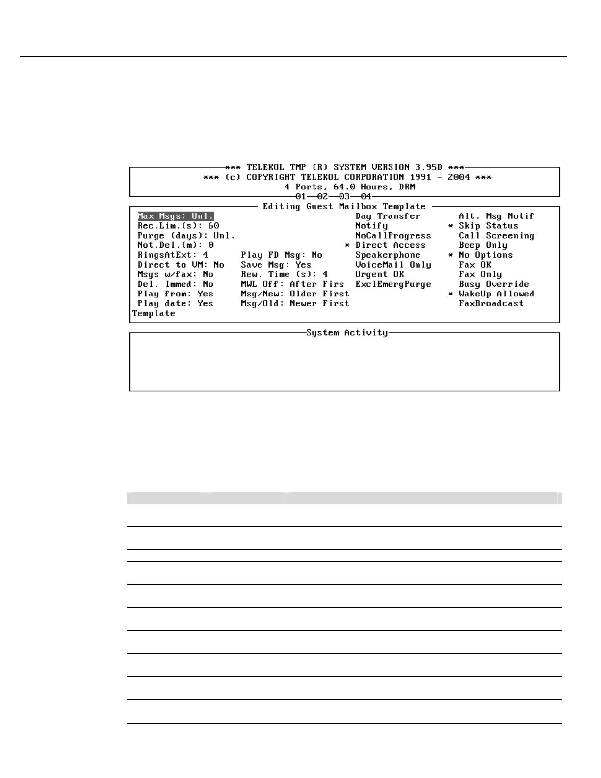
Section 4: Optional Equipment Installation & Configuration
Template Mailboxes
The setting of the guest mailbox template affects all guest mailboxes. Anytime a change is made
the template, all active and newly created guest mailboxes will have the new template settings.
Editing the Guest Mailbox Template and acce
se the Administrative password (default 9876).
U
to
ssing the Administrative menus requires a password.
Figure 4-14: Guest Mailbox Template Screen — To access from the Hospitality Main Menu,
press [E], access code, [E].
The Hospitality module guest template is factory configured and can be used in most cases without
further change. The parameters of the guest MB template are a subset of the regular mailbox
parameters. These parameters are:
FIELD DEFAULT DESCRIPTION
Del. Immed No When set to “Yes”, deleted messages are removed from the
disk immediately and cannot be ‘undeleted’.
Direct to VM No When set to “Yes”, calls are transferred immediately to Voice
Mail, without attempting to transfer to the extension first.
Max Msgs Unl. Maximum number of messages allowed in this mailbox.
Msg/New Oldest First Determines the order in which new messages are played,
possible settings are Oldest First or Newest First.
MWL Off After First Determines when the MWL is turned off, After First new
message was heard or After All new messages.
Msg/Old Newest First Determines the order in which old messages are played.
Possible settings are Oldest First or Newest First.
Msgs w/Fax No Determines whether or not a voice message can be left with
a fax. Applicable only with Fax Options installed.
Play from Yes System plays the name of message-senderbefore the
message is played.
Play date Yes System plays the time and date of the message after the
message is played.
Purge Time Unl. Number of days that a message can remain in (days) a
mailbox.
68 TVM-2000 Technical Reference Manual
Page 83

Section 4: Optional Equipment Installation & Configuration
FIELD DEFAULT DESCRIPTION
Rec. Limit
(secs)
Rew. Time (s): 4 Number of seconds to rewind or skip forward while listening
RingsAtExt 4 Number of rings at the extension before no answer is
Save Msg Yes When set to “No”, messages are deleted automatically
Day Transfer No When set to “Yes”, transfers calls to the extension in day
Notify No When set to “Yes”, the system informs the user which
NoCallProgress No When set to “No”, the system performs supervised tr
Direct Access Yes When set to: “Yes,” the caller can only leave a message, and
Speakerphone No When set to: ”Yes,” the system announces the call via the
Voic When set to: “Yes,” the system does not attempt to transfer
eMail Only No
Urgent OK etermines whether urgent messaging is allowed for guest No D
Alt. Msg Notif No When set to: “Yes,” uses the alternate message notification
Skip Status Yes Does not play Busy / No Answer message.
Call Screening No When set to: “Yes,” call screening is enabled for all guests.
Beep Only No When set to: “Yes,” the system
No Options Yes When set to: “Yes” callers are
Fax OK No Setting to “Yes” enables Fax Mail for the guests (Requires
Fax Only No Setting to “Yes” limits guest mailboxes to only receiving
Busy Override No Setting to “Yes” allows busy override for all guest mailboxes.
Call Recording No Setting to “Yes” 2-way Call Recording is enabled.
60 Maximum message length in seconds.
to a message.
transfer. determined in a supervised call
immediately after they have been
guest may need to ac
mode only.
to the extension.
no other menu options are made available.
speaker phone.
to the extension and places the caller in voice mail
ediately.
imm
mailboxes.
sequence.
after the tone.” prompt.
Fax Options).
faxes.
cess old messages.
messag
listened to. Set Yes if your
onnecting the call. mailbox was dialed before c
skips the “Begin recording
not offered any options after
e. they have recorded a
ansfers
TVM-2000 Technical Reference Manual 69
Page 84
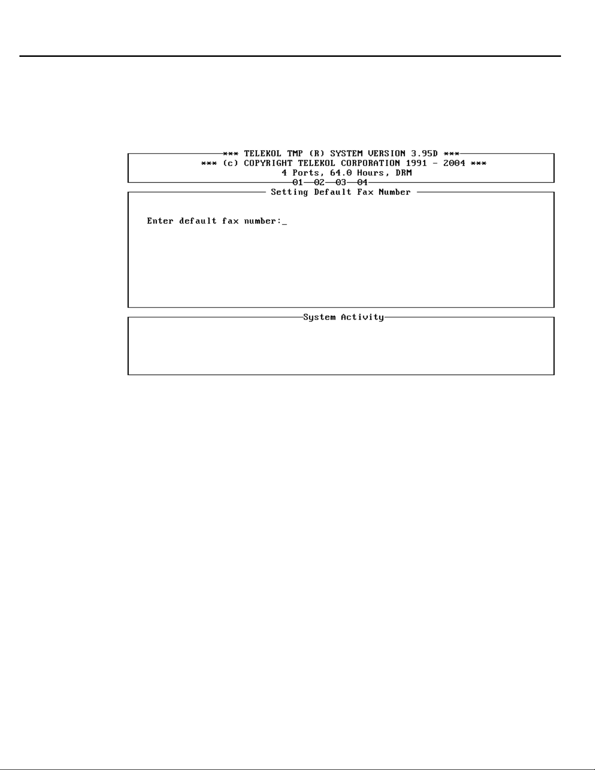
Section 4: Optional Equipment Installation & Configuration
Using the Fax Module with the Hospitality Option
If the system is also configured with the Fax Module, you can se
ne. Access the Default Ffront desk fax machi
number to which the fax machine is assigned.
t up the front desk fax machine
This will allow guephone number or extension to retrieve faxes.
sts to direct incoming faxes to the
ax Number screen and enter the extension or phone
Figure 4-15: Default Fax Number Screen — To access from the Hospitality Main Menu, press
[E], access code, [F].
70 TVM-2000 Technical Reference Manual
Page 85

Section 4: Optional Equipment Installation & Configuration
Wake Up Calls
The TVM-2000 Hospitality Module allows for wake up calls to be programmed from both the Fr
Desk and Guest extensions. The wake up calls ring guest rooms or outside lines.
To Add a Wake Up Call Request From the Front Desk
hospitality is enabled, the default screen is the Hospitality Screen.
If
1. From the Hospitality Main Menu, enter [W] to set a Wake up call.
2. Enter the desired wake up call time in 24-hour format.
The system will redisplay the desired wake up call time.
To Add a Wake Up Call Request From Guest Extension
To prevent users from programming Wake Up calls from telephone extensions, see “To
Enable/Disable Wake Up Calls (System Wide)” below.
1. From the Mailbox Owner’s Main Menu, select [6]. The user is presented with the following
options:
WAKE UP OPTIONS MENU
[1] To add a wake up call
[2] To cancel a wake up call
[3] To list all wake up calls
[#] Exit and return to the previous menu
2. Press [1] to add a wake up call.
3. Enter the desired time and date of the wake up call in 24-hour format.
To Remove a Wake Up Call From the Front Desk
If hospitality is enabled, th
e default screen is the Hospitality Screen.
1. From screen, e
2 he wake
. Enter the number of t
the Hospitality
nter [C] to Clear a Wake up call.
up call you wish to clear.
T ke Up Call F
o Remove a Wa rom a Guest Extension
1 ailbox Owner’s
. Access the M
2. Select [6] r Wake Up call o
. Select [2] to cancel wake up calls.
3
fo
Main Menu.
ptions.
4. The TVM-2000 will say the time and date of any previously set wake up calls. Press 1 to delete
the call.
ont
TVM-2000 Technical Reference Manual 71
Page 86

Section 4: Optional Equipment Installation & Configuration
To Enable/Disable Wake Up Calls (System Wide)
1. Enter [E]dit Guest Mailbox Template from the Main Menu
2. Enter the access code (9876 by default).
. Enter [E] again.
3
4. Activate (put a “*” next to) t
he WakeUp Allowed field to enable a Guest to activate a wake up
call via the telephone.
To Enable/Disable Wake Up Calls (Per Mailbox)
1. Enter [M]ailbox Setup/Edi
. Select «Mailbox Attr.».
2
ting from the Main Menu.
3. Set the WakeUp Allowed parameter to enable or disable wake up calls.
To View Scheduled Wake Up Calls
1. From the Main Menu, select [M]ailbox Setup/Editing.
2. Select «Wake Up». The TVM-2000 will display the time and number of existing wake up calls.
Wake Up Call Reports
To view a report of scheduled wake up calls:
1. Enter [R]eports from the Main Menu.
2. Enter [W]ake Up Call Reports.
3. Enter the number of the mailbox for which you wish to see scheduled wake up calls, or press
[Enter] to see a report on all mailboxes.
4. Enter the start date and end dates for which you wish to see scheduled wake up calls.
5. Enter the name of the file to which you wish to have your report printed.
Notes about wake up calls
• *4 Inbound Rings and *4 Outbound Rings should be set to a value that is less than the number
of rings to extension before transferring to Voice Mail.
• Minutes between wake up attempts and number of wake up attempts can be set in the
[A]dvanced..., [M]ore..., «Other» screen.
• Three wake up times are allowed per room.
• Wake up calls are considered to be the “next time around.” For instance, if you set a wake up
time at 5:00 p.m., the next time 5:00 p.m. comes around (regardless of the date) it is used.
• A wake up call is considered “Complete” when someone answers the phone. At this point, a
voice will come on and say, “This is your wake up call. The current time is xx:xx..”
.
72 TVM-2000 Technical Reference Manual
Page 87
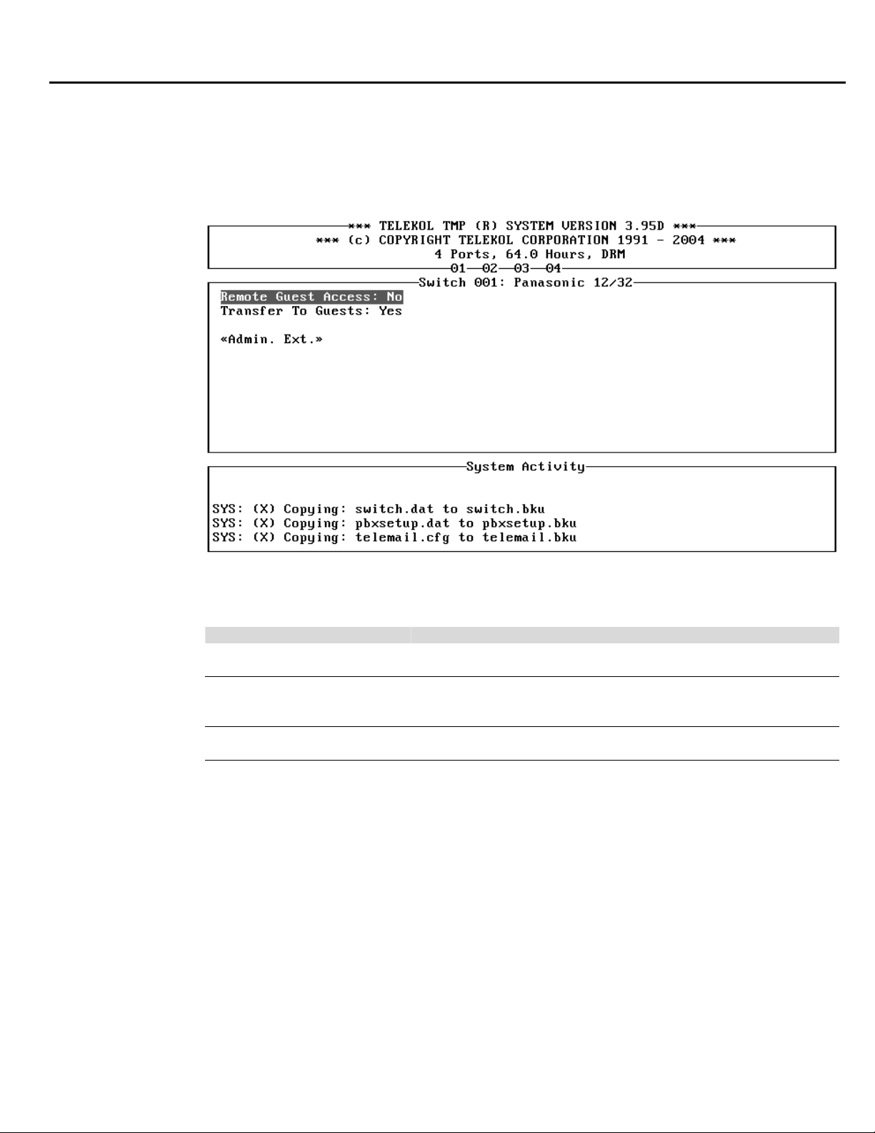
Section 4: Optional Equipment Installation & Configuration
Advanced Hotel Parameters
addition to the setting of the guest mailbox te mplate and the default fax machine number, the
In
Hospitality feature offers parameters that determine whether guests can access the voice mail only
from their room or also from other locations; and whether the system uses the automated att
transfer calls to guest rooms, or operator intervention is required.
endant to
Figure 4-16: Hotel Advanced Parameter Settings Screen — To access from the Main Menu,
press [A], [M], «Hotel».
FIELD DESCRIPTION
Remote Guest Access Enables or disables access to guest mailboxes from an internal
extension or an outside line.
. When Transfer to Guest When set to “Yes”, caller may dial room extension directly
set to “No”, the Voice Mail requires operator intervention for
transfer to room extension.
«Admin. Ext.» Accesses Admin Ext. screen, enabling the activation of up to ten
Admin. mailboxes.
Remote Guest Access indicates whether or not a guest needs a password to access messages. If set to
“No,” messages can only be heard from th
to “Yes,” guests must access the Voice M
set, messages can be accessed from any telepho
e guest’s room or from an administrative extension. If set
ail from their rooms first and set their access code. Once
ne capable of accessing the TVM-2000.
Regardless of the setting, when guests calls from th r an administrative extensions, the
TVM-2000 will not ask for a password.
eir rooms o
TVM-2000 Technical Reference Manual 73
Page 88
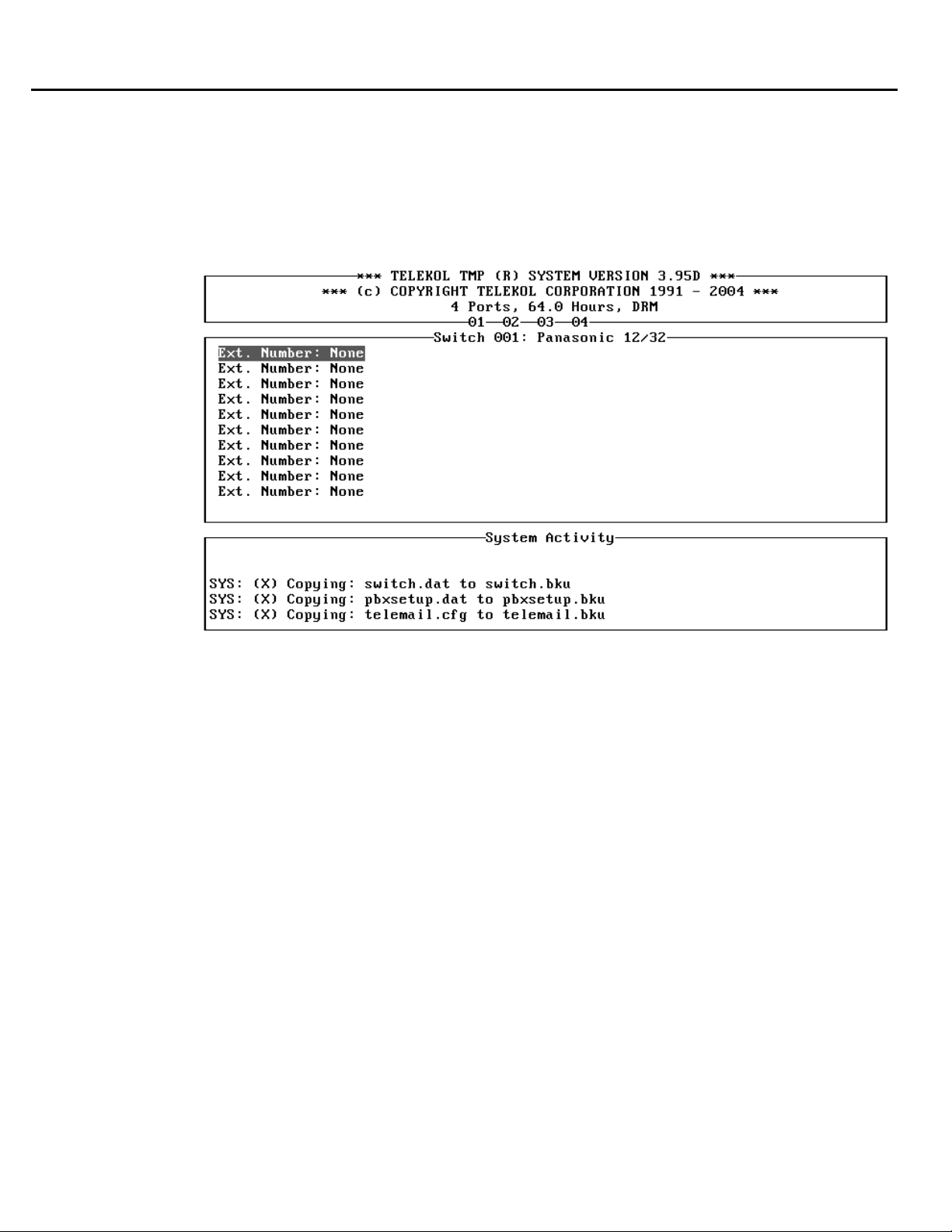
Section 4: Optional Equipment Installation & Configuration
Transfer
Transfer t
to Guests
o Guests allows the Voice Mail to transfer calls directly to the guest mailboxes. If this
parameter is disabled, the caller must dial [9] + [Extension]. If callers enter just the room num
they will hear “The selection you’ve made is not valid. Please make another selection.”
Administrative Extensi
The Administrative Extens
ons
ions screen allows the up to 10 administrative extensions to be set.
ber,
Figure 4-17: Administrative Extension Screen — To access from the Main Menu, press [A],
[M], «Hotel», «Admin.Ext».
his option permits setting up to ten Administrative phone extensions. Administrative extensions are
T
sed to allow access to guest mailboxes from outside the room WITHOUT requiring a password. For
u
example, if messages arrive for guests while they are checking out, they could use the operator’s
phone to listen to these messages without having to return to their room.
74 TVM-2000 Technical Reference Manual
Page 89
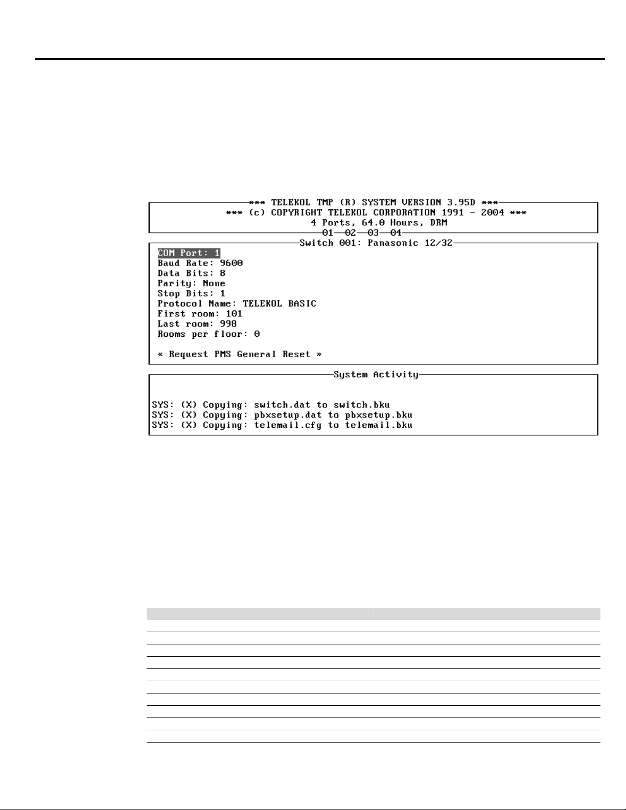
Property Management System (PMS)
The Property
industry. The simple interface allows front desk personnel to check in and check out guest
mailboxes. The auto-attendant can be programmed to answer calls for both guests and hotel
administrators, or for administrators only. The guest mailboxes can be password protected to secure
private access to messages from outside the room. This module also features a quick automatic
wake-up call scheduling function, and integrates fully with many Property Management Systems.
Management System (PMS) Module was developed exclusively for the Hotel/Motel
Section 4: Optional Equipment Installation & Configuration
Figure 4-18: PMS Setup Screen — To access from the Main Menu press [A], [M], «Other»,
«PMS Setup».
First room, Last room and Rooms Per Floor parameters are used to narrow the continuous
numeration to the actual room numbers. It is assumed that every floor has the number of Rooms Per
Floor rooms starting with a room number ending on 01. If Rooms Per Floor = 0, the TVM-2000 uses
continuous numeration from the First room to the Last room.
The “Request PMS General Reset” button is used to send the Reset Request message to the PMS.
Supported PMS systems
Following is a list of supported PMS systems:
COMPANY PROTOCOL NAME
Computel Computel
Encore Systems, Inc. Teletech
First Resort Systems Teletech
HSS Limited Telekol Basic
Innsoft Telekol Basic
Remco Software Remco
Resorts Data Processing Telekol Basic
Softech Telekol Basic
Sulcus Hospitality Group/Lodgistix Lanmark
Innsoft Innsoft
TVM-2000 Technical Reference Manual 75
Page 90

Section 4: Optional Equipment Installation & Configuration
System Upgrades
Adding voice mail ports, fax ports, and system storage is done by contacting Telekol’s Sales
Department. Instructions for each upgrade come with the upgrade diskettes.
Multilingual Software (MLS)
If purchased as part of a new TVM-2000 system, Multilingual Software (MLS) will be installed and
tested at the factory. When purchased as an upgrade, the software is delivered on a 3-1/2" diskette.
To install the upgrade, follow the steps below:
1. Insert the diskette into the A: drive on your TVM-2000.
2. Go to [U]tilities, [U]pgrade TVM System.
3. Follow the instructions on the screen to complete the installation.
To Use the Multilingual Option
If the multilingual software is installed, the TVM-2000 automatically plays the multilingual greeting
as part of the welcome message. The default multilingual portion of the welcome message is “For
English, press 1. For Spanish, press 2.” To record over the default multilingual welcome message,
access the administrator side and then enter ‘2’ + ‘3’ + ‘7’.
The rest of the multilingual messages are accessed by first calling the TVM-2000, accessing the
respective language, pressing “*” and then accessing the administrator mailbox.
Foreign Language Support (FLS) modules
Foreign Language Support (FLS) modules include all recorded generic greetings for use with the
MLS option. Up to nine foreign language modules can be used with each TVM-2000 system.
76 TVM-2000 Technical Reference Manual
Page 91

TVM-2000 Technical Reference Manual 77
Page 92

78 TVM-2000 Technical Reference Manual
Page 93

Section 5:
System Testing
Test Procedu
re
The following steps outline the test procedure to verify that your TVM-20
and configured correctly.
. Dial into each voice mail port to test incoming ring detection.
1
2. If Automated Attendant is configured,
Menu Part 1, Single-Digit menu, a
3. Test BUSY / NO ANSWER / PIC
times to verify proper detection.
4. If automated attendant is utilized, verify that a call is transferred properly and taken back into
TVM-2000 unit onc
5. Leave several messages for different mailboxes and retrieve them. Use varying messa
to test the limits set.
. Verify that the message lights are turned on and off appropriately.
6
7. Test each of the other notificatio
a with calls from both internal extensions and CO lines.
e a call has not been answered or if the extension dialed is busy.
e systemM ke sure you have tested th
call the voice mail to test the Welcome Message, Main
nd Main Menu Part 2.
KUP detection supervised mode. Repeat each condition five
n functions and follow-me methods active on the system.
00 unit has been installed
ge lengths
the
TVM-2000 Technical Reference Manual 79
Page 94

Section 5: System Testing
Troubleshooting
installing or configuring the TVM-2000. Please read this section thoroughly befo
Support.
o
H w to Troubleshoot
In order to effectively troubleshoot, the following items should b
1. This Manual
.
Butt-In Test Set (Butt Set) 2
3. Keyboard and VGA monitor (or serial communications device).
4. Digit Grabber
Following the steps listed below will make troubleshooting a more systematic process:
1. Collect sufficient information to fully define the parameters of the problem.
.
Attempt to duplicate the problem. 2
. Evaluate the information and isolate problems from symptoms. (Often, multiple problems are
3
actually symptoms of the same problem)
4. Determine the cause of failure.
5. Take corrective action.
6. Test the system, and make sure the problem has been corrected.
s encountered wThis section provides a list of steps that should be followed if a problem i
re calling Technical
e available for use:
hile
80 TVM-2000 Technical Reference Manual
Page 95

System Trouble
System troubles are problems that are occurring for more than one user, and to both internal an
external callers.
allers are being disconnected from the system:
C
• Verify that calls are being transferred properly.
• Increase the num
• The system may b
Calls are not transferring properly:
• Try both inside and outs
• Verify that the mailbox is ac
• Check the mailbox type. (i.e. Voice Mail Only, Day Transfer Only, etc.)
Calls are not being answered:
• Verify that the unit is turned on.
• Check port connections.
• Verify the proper operation of the extensions to which the TVM-2000 is connected.
• Check the Answer On Ring parameters in port specific options.
Check phone system programming. •
•
he system does not recognize DTMF:
T
•
The single-digit menu is not functioning properly:
• Verify that the single-digit menu message has been recorded.
• Verify that the SINGLE DIGIT MENU ACTIVE parameter is set to YES.
• Verify that the ACTIVE AT NIGHT parameter is set properly.
• Check the digit selections, and verify that they correspond to active mailboxes.
The dial-by-name directory does not work:
• Confirm that all mailbox owners’ names have been recorded and entered in the mailboxes.
• Verify that the name search feature has been enabled in system configuration.
• Check the DIRECTORY MB: parameter in system configuration, and make sure that it is set
The Day, Night, and Special Welcome Messages are not playing:
• Verify that the greetings have been recorded.
• Be sure that the system is in the proper mode, i.e. day, night, or special.
• Check the time and date settings on the system.
• Ensure that the message numbers in the operations screen are set properly.
Section 5: System Testing
ber of Retries On No Input in system configuration.
e disconnecting on silence prematurely. Increase the RSilenceLimit parameter
in advanced
switch configuration.
ide calls
tive.
witch default has been loaded.
r s• Make sure that the prope
arameters in the advanced switch configuration screen. (Flash timer,
nsfer p• Check the call tra
digits to dial, etc.)
Verify the proper operati• on of the extensions to which the TVM-2000 is connected.
If the problem persists check if all the ports are busy.
Verify that the phones are sending valid DTMF signals.
properly.
d
TVM-2000 Technical Reference Manual 81
Page 96

Section 5: System Testing
The system cannot be accessed through a serial communications device:
•
• If a local device is being used, verify that a null modem cable is being used.
• Be sure that the cable is plugged into the serial port with the DB-9 connector
• Be sure that the communications software is configured to support 19,200 baud, no parity, 8 data
• Verify that the Port Location parameter is set appropriately.
• If the modem is being used, verify that a phone line is plugged into the LINE jack, and that the
Some cables hold pin 9 high, which prevents the connection from being made. In that case,
cutting pin 9 resolves the problem.
The TVM-2000 hangs up on the caller after playing the welcome message:
• Check that the operator mailbox exists. See “Setting Up Multi-tenant & Multilingual Operator
Make sure that the remote communications utility has been enabled.
bits, 1 stop bit; and is configured for VT-100 terminal emulation.
correct phone number is being dialed.
(General Delivery) Mailboxes” on page 47.
82 TVM-2000 Technical Reference Manual
Page 97

Calling Technical Support
Telekol’s Technical Support Group takes pride in its abi
. Technical support is available to Telekol Au
1-800-797-0123.
hen calling the TechniW
and items available:
• Customer Name
Site Nam•
• Call Back Phone Number
• System Model and software version numb
System Serial Number •
• Phone System Information
Keyboard and Monitor •
• Butt-
• entatio
System Docum
• f the pro
Description o
details you can provide, the better our technical support personnel can assist you.
If a technical support representative is not available to assist you immediately, you will be able to
l describin and
eave a message
f to available re er
orwarded
of the sy del, tele s the system is
e echnica
xperiencing. A T
e
In Test Set
Section 5: System Testing
lity to assist customers promptly and
thorized Dealers only at efficiently
cal Support Group, please be on site, and have the following information
er
n
blem. Verify, if possible, that you can reproduce the problem. The more
g the problem you are experiencing. Messages are constantly retrieved
presentatives. Please leave a detailed message, including the serial numb
phone system and a destem, mo
tailed description of the symptom
l Support Representative will call back shortly.
TVM-2000 Technical Reference Manual 83
Page 98

84 TVM-2000 Technical Reference Manual
Page 99
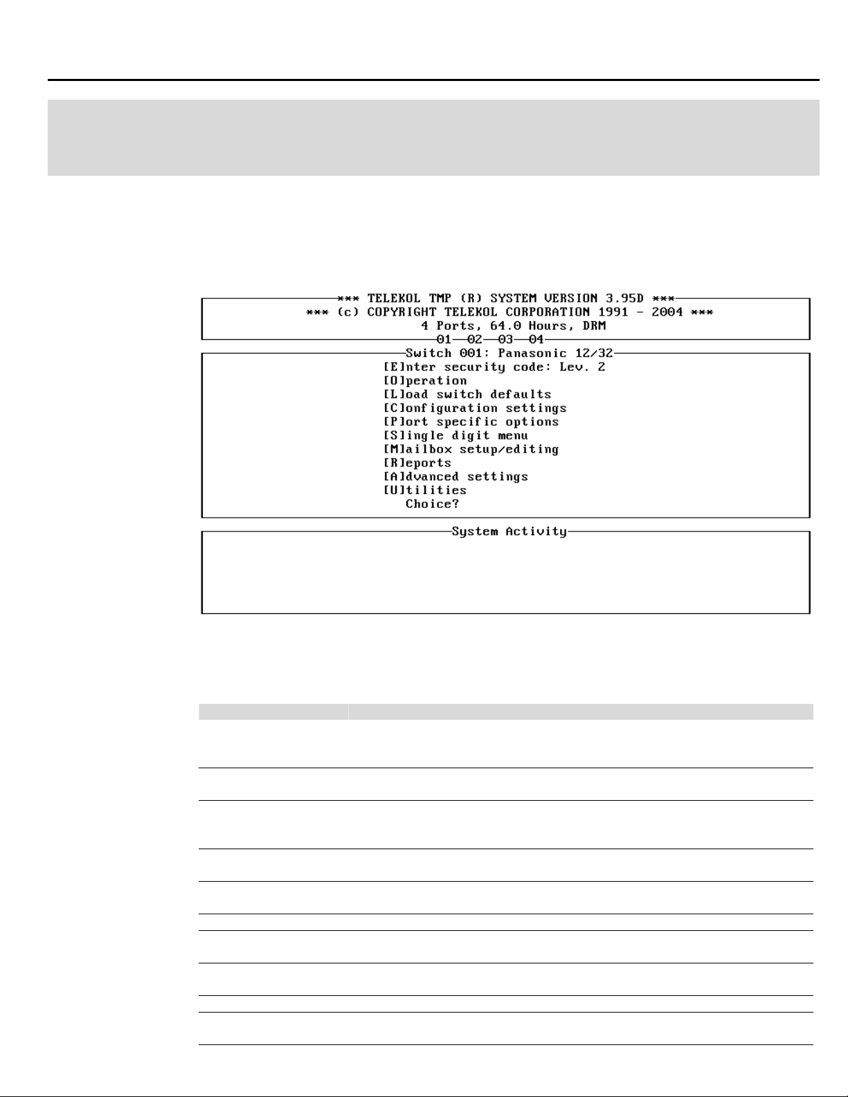
Administrative Main Menu
T nu sc VM-2000
he administrative Main Me reen is the first screen displayed upon powering up the T
s
ystem.
Section 6:
System Reference
Figure 6-1: TVM-2000 Main Menu screen.
The options available in the Setup/Options window are as follows:
FIELD DESCRIPTION
[E]nter Security
Code:
[O]peration Sets system-wide parameters, such as Date, Time, Operator Mailbox,
[L]oad Switch
Defaults
[C]onfiguration
Settings
[P]ort Specific
Options
[S]ingle Digit Menu Assigns and enables settings for the single digit menu.
[M]ailbox
Setup/Editing
[R]eports Lists the available reports about the system and the mailboxes and
[A]dvanced Settings Details advanced settings for entire TVM-2000 system.
[U]tilities Lists available utilities, such as backup, restore, upgrade, and routine
Allows access to the administrative functions. It is recommended Lev. 2
that only authorized dealers change this parameter. The default is Level
2.
Business Hours, and Holidays.
Enables automatic default parameter settings for individual telephone
switches through the entry of a switch default code found in the Preset
Switch Default Table.
Sets Voice Mail-specific system configuration options.
Enables and configures parameters and functions for individual Voice
Mail ports or port groups, e.g., multi-tenant switch configurations.
Activates, edits, and deletes individual mailbox settings for all mailbox
types.
enables requests to be sent to printer or text file.
maintenance.
TVM-2000 Technical Reference Manual 85
Page 100
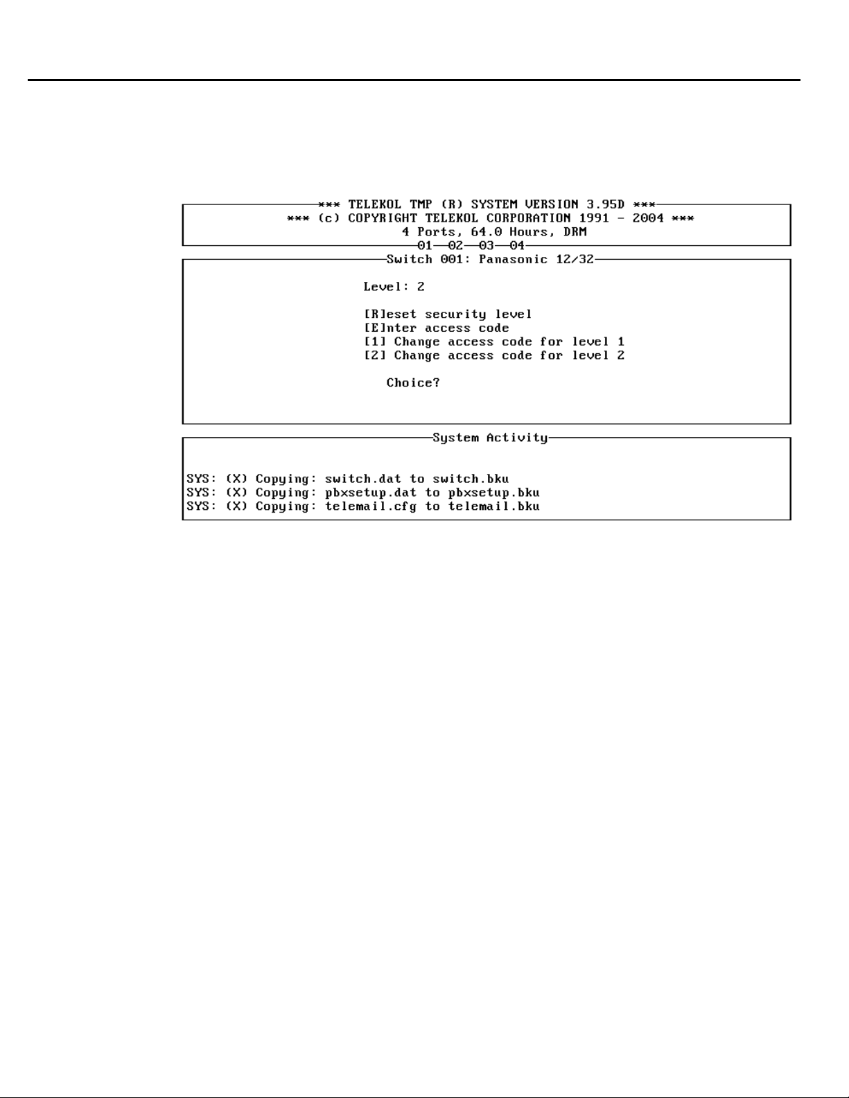
Section 6: System Reference
Enter Security Level Screen
he Enter Security Level screen controls access to all of the screens in the TVM-2000 T
Administrativ
e Menu structure.
Figure 6-2: Enter Security Level Screen. — To access from the Main Menu, press [E].
There are three security levels:
Level 0: Allows access the Enter Security Level screen ONLY.
Level 1: Allows access to the Operation, Reports, and Enter Security screens
Level 2: Allows acc
The default is level 2. To change the security level, first create or enter a security code. By default,
there is no security code. Once security codes have been entered, pressing [ESC] changes the
security level to the level accessed by the entered security c
ess to all screens.
ode.
86 TVM-2000 Technical Reference Manual
 Loading...