

Telegesis ZigBee RangeFinder ZHT100, ZigBee RangeFinder SAT100 Product Manual
Telegesis ZigBee RangeFinder
©2012 Telegesis (UK) Ltd -1- Telegesis ZigBee RangeFinder
Telegesis
TG-RF-PM-501 ZigBee RangeFinder
ZigBee RangeFinder
Product Manual 0501 r2
Telegesis ZigBee RangeFinder
Product Manual
Rev: 2
Date: Jan 2013
Patent pending: GB1222898.7

Telegesis ZigBee RangeFinder
©2012 Telegesis (UK) Ltd -2- Telegesis ZigBee RangeFinder
Table of Contents
Table of Contents .............................................................................................................................. 2
Package Contents ............................................................................................................................. 5
Specifications .................................................................................................................................... 6
Handheld Terminal (HHT).............................................................................................................. 6
Satellite (SAT-x) ............................................................................................................................ 6
Handheld Terminal Unit .................................................................................................................... 7
Layout ........................................................................................................................................... 7
Functionality .................................................................................................................................. 9
Start-up: ................................................................................................................................... 10
Menu Screens: ......................................................................................................................... 11
Normal Test Modes: ................................................................................................................. 12
Continuous Test Modes: .......................................................................................................... 16
Device Configurations: ............................................................................................................. 22
Firmware Upgrades: ................................................................................................................ 26
Data Logging: .......................................................................................................................... 29
Power .......................................................................................................................................... 32
Batteries .................................................................................................................................. 32
Charging .................................................................................................................................. 32
Power Saving ........................................................................................................................... 32
Satellite Unit .................................................................................................................................... 33
Layout ......................................................................................................................................... 33
Functionality ................................................................................................................................ 34
Buttons .................................................................................................................................... 34
LEDs ........................................................................................................................................ 34
Power .......................................................................................................................................... 35
Batteries .................................................................................................................................. 35
Power Consumption ................................................................................................................. 35
Usage ............................................................................................................................................. 35
System Topology ......................................................................................................................... 35
Workflow ..................................................................................................................................... 37
Interpreting Test Results ................................................................................................................. 38
RSSI Calculation ...................................................................................................................... 38
Packet Error Rate .................................................................................................................... 38
Pass/Fail Criteria ...................................................................................................................... 38
Warranty ......................................................................................................................................... 39

Telegesis ZigBee RangeFinder
©2012 Telegesis (UK) Ltd -3- Telegesis ZigBee RangeFinder
Compliance with Laws and Regulations .......................................................................................... 41
Disclaimer ....................................................................................................................................... 41
Contact Information ......................................................................................................................... 41

Telegesis ZigBee RangeFinder
©2012 Telegesis (UK) Ltd -4- Telegesis ZigBee RangeFinder
Table of Figures
Figure 1: Package Contents .............................................................................................................. 5
Figure 2: Handheld Terminal Front .................................................................................................... 7
Figure 3: Handheld Terminal Back ................................................................................................ .... 8
Figure 4: Product Label ..................................................................................................................... 9
Figure 5: Start-up Screen ................................................................................................................ 10
Figure 6: Start-up Screen ................................................................................................................ 11
Figure 7: Pre-Test Screen ............................................................................................................... 12
Figure 8: Test Start Screen ............................................................................................................. 13
Figure 9: Screen for Test A and B ................................................................................................... 14
Figure 10: Energy Scan Screen ...................................................................................................... 15
Figure 11: Tx tone ........................................................................................................................... 16
Figure 12: Continuous Ping Configuration ....................................................................................... 17
Figure 13: Continuous Ping Results ................................................................................................ 18
Figure 14: Single Channel E-Scan .................................................................................................. 19
Figure 15 One hop configuration screen ......................................................................................... 20
Figure 16 One Hop Test Result Screens ......................................................................................... 21
Figure 17: Configurations Screen .................................................................................................... 23
Figure 18: Advanced Configurations Screen ................................................................................... 24
Figure 19: Configurations Parameter Limits .................................................................................... 25
Figure 20 Firmware Upgrade Screens ............................................................................................ 26
Figure 21 HHT Firmware Upgrade .................................................................................................. 26
Figure 22 HHT Firmware upgrade options ...................................................................................... 27
Figure 23 SAT Firmware Options .................................................................................................... 28
Figure 24 Data Logger Screen ....................................................................................................... 29
Figure 25: Battery Symbol ............................................................................................................... 32
Figure 26: Battery Charging Symbol ............................................................................................... 32
Figure 27: Satellite Front ................................................................................................................. 33
Figure 28: Satellite Back ................................................................................................................. 33
Figure 29: Satellite Product Label ................................................................................................... 34
Figure 30: Satellite LED States ....................................................................................................... 34
Figure 31: A typical floor plan with Smart Energy equipment locations ............................................ 35
Figure 32: RangeFinder locations: Electric meter, Gas meter and Kitchen work surface ................. 36
Figure 33: Workflow ........................................................................................................................ 37
Telegesis ZigBee RangeFinder
©2012 Telegesis (UK) Ltd -5- Telegesis ZigBee RangeFinder
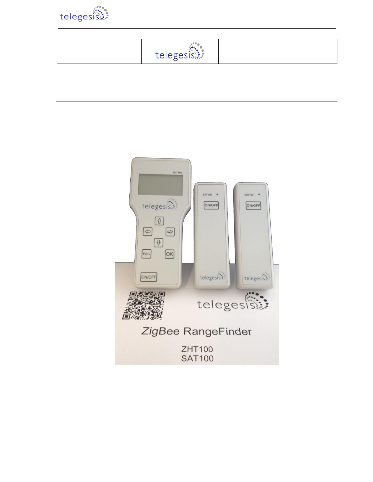
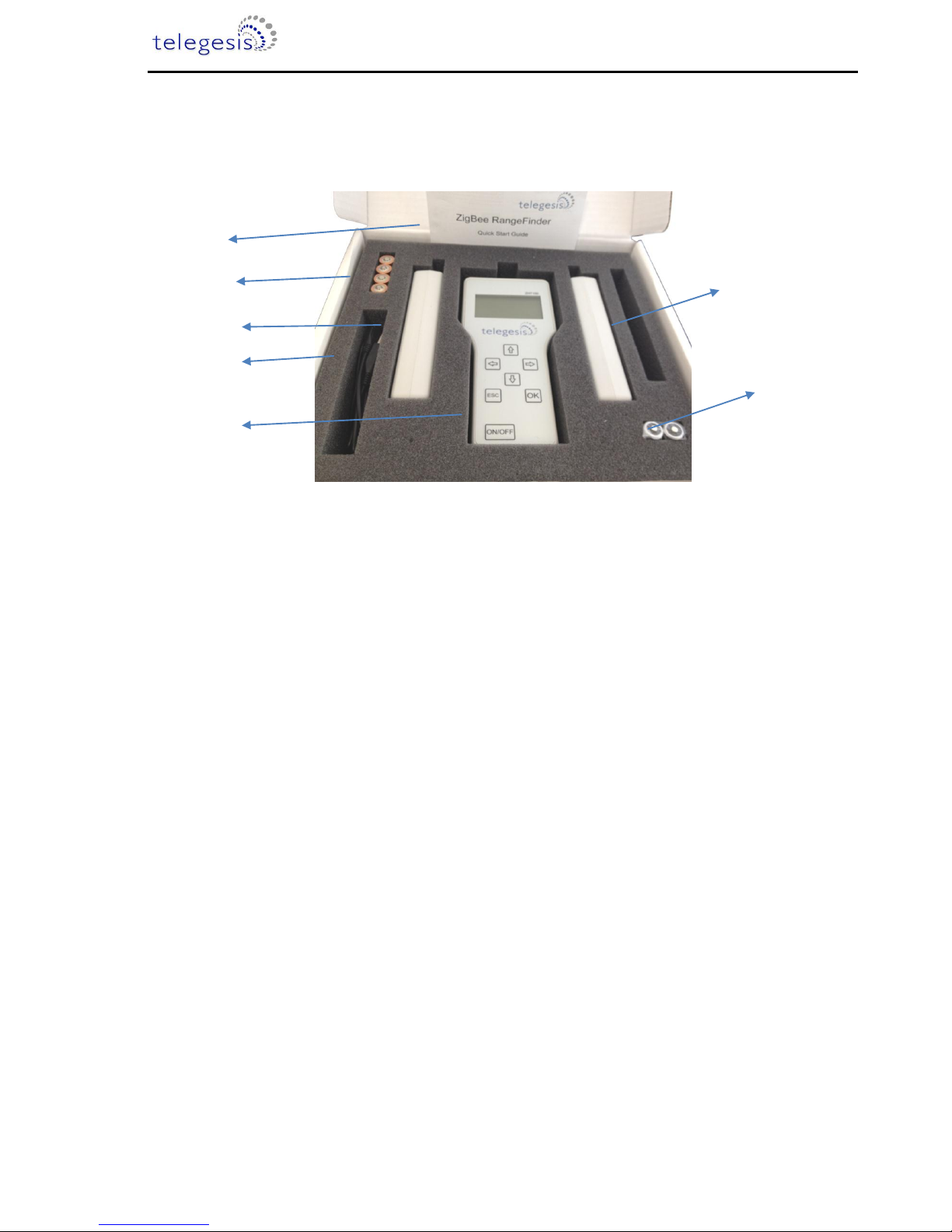
Package Contents
The package contains the following items,
Figure 1: Package Contents
a) 1x Quick Start Guide
b) 4x 1.5V AA Alkaline Batteries
c) 2x Satellite Units SAT100
d) 1x USB A to USB Micro Cable
e) 1x Handheld Terminal ZHT100
f) 2x 1.2V AA 2000mA Rechargeable Batteries
g) 3x 2.4GHz Half-wave Antennas
(a)
(b)
(c)
(d)
(e)
(f)
(g)

Telegesis ZigBee RangeFinder
©2012 Telegesis (UK) Ltd -6- Telegesis ZigBee RangeFinder
Specifications
Handheld Terminal (HHT)
Model Number
ZHT100
RF Interface
2.4GHz IEEE802.15.4
RF Output Power
-9dBm to +8dBm
Antenna
Half-wave Dipole Antenna 2dBi Gain
Battery
2x 1.2V 2000mAH NiMH Rechargeable
Expected Battery Life
Tbd
Charging
5Volts @ 300mA via USB Micro Connector
Operating Temperature
0 to 50C
Humidity
95% TH Non-condensing
IP Rating
IP54 (subject to testing)
Satellite (SAT-x)
Model Number
SAT100
RF Interface
2.4GHz IEEE802.15.4
RF Output Power
-9dBm to +8dBm
Antenna
Half-wave Dipole Antenna 2dBi Gain
Battery
2x 1.5V AA Alkaline Batteries
Expected Battery Life
Tbd
Operating Temperature
0 to 50C
Humidity
95% TH Non-condensing
IP Rating
IP54 (subject to testing)
Telegesis ZigBee RangeFinder
©2012 Telegesis (UK) Ltd -7- Telegesis ZigBee RangeFinder
Handheld Terminal Unit
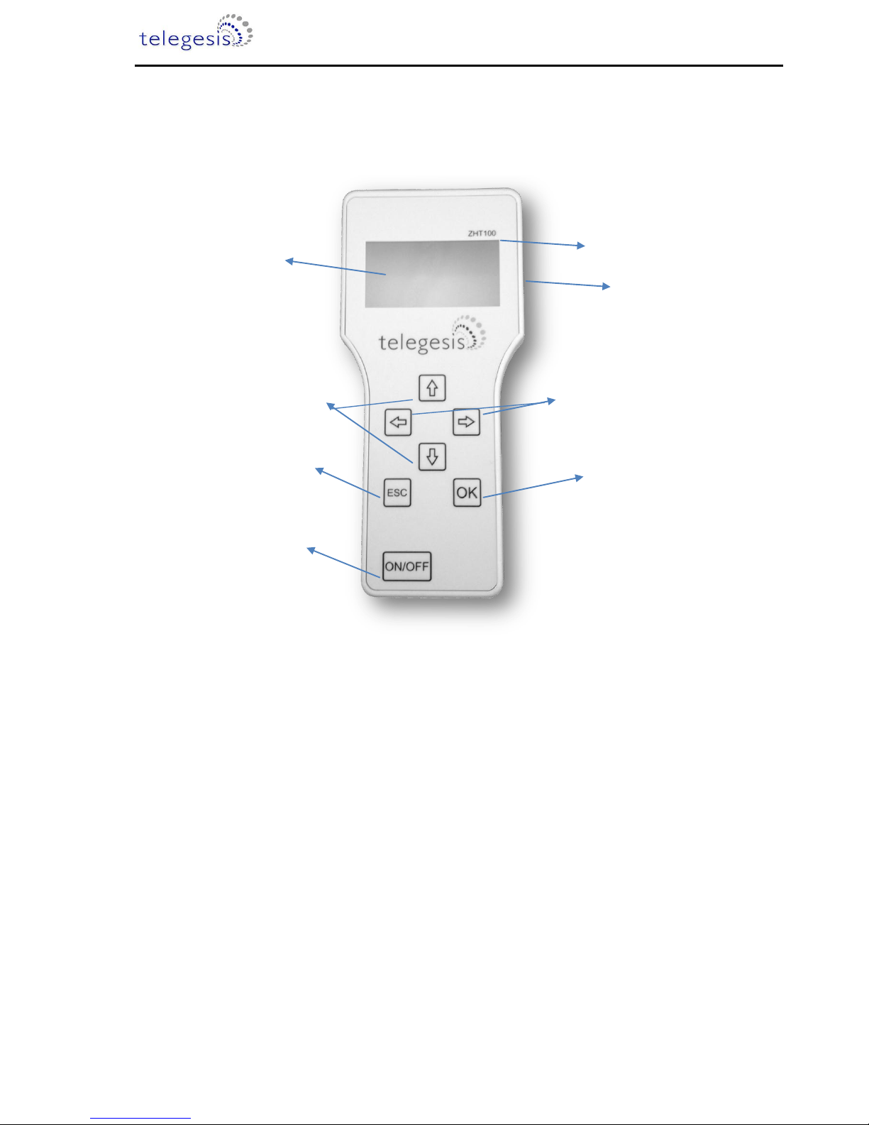
Layout
Figure 2: Handheld Terminal Front
Handheld Terminal Front
(a) Product Model Number
(b) LCD Display
(c) Navigation Keys
(d) Value Change Keys
(e) Escape (Back) Key
(f) Enter (Activate) Key
(g) Power On/Off Key
(h) USB-B Micro Connector
(h)
(a)
(b)
(c)
(f)
(e)
(g)
(d)
Telegesis ZigBee RangeFinder
©2012 Telegesis (UK) Ltd -8- Telegesis ZigBee RangeFinder
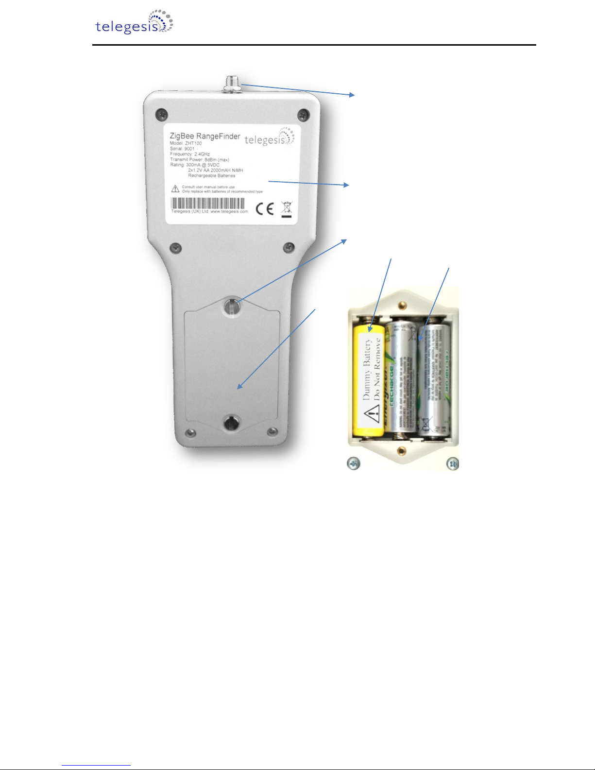
Figure 3: Handheld Terminal Back
Handheld Terminal Back
(a) SMA Connector for Antenna
(b) Product Label
(c) 2x Screw for Battery Compartment
(d) Battery Compartment
(e) Dummy Battery (non-removable)
(f) 2x Rechargeable Batteries
(a)
(b)
(d)
(c)
(f)
(e)
Telegesis ZigBee RangeFinder
©2012 Telegesis (UK) Ltd -9- Telegesis ZigBee RangeFinder
Functionality
The Hand-Held Terminal (HHT) is the centre point of the system and all communication in
the system is with respect to the HHT. The operator can set up parameters for tests, perform the
tests and configure other test settings from the HHT. Below are the explanations of various options
and output screens one can use on the HHT.
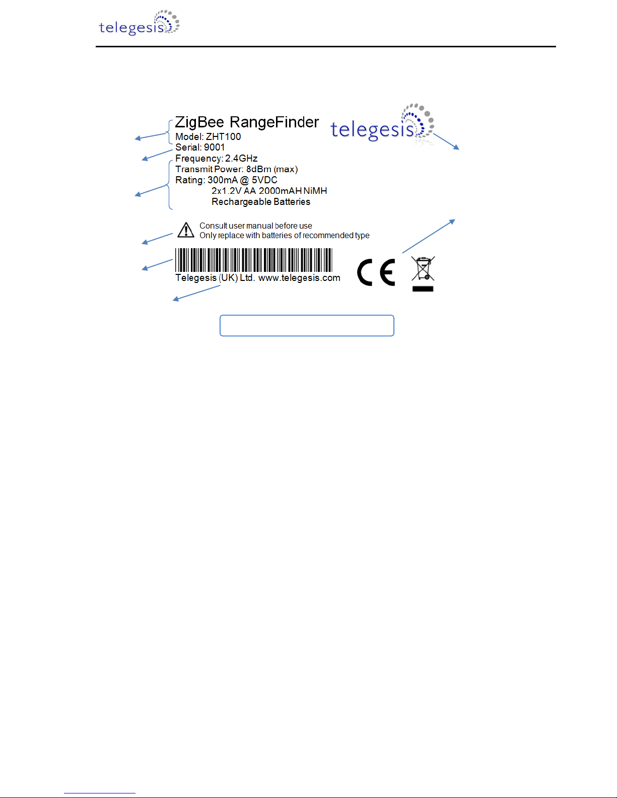
Figure 4: Product Label
Handheld Terminal Label
(a) Product name “ZigBee RangeFinder” and product model number “ZHT100”
(b) Serial number of the product
(c) Operating parameters of the product
(d) Warning
(e) Barcode with following content:
<Model>/L<Serial>
e.g. ‘ZHT100/L9001’
(f) Compliance marking for CE and WEEE
(g) Manufacturer’s logo
(h) Manufacturer’s contact information
(a)
(b)
(c)
(d)
(e)
(f)
(g)
(h)
Patent pending: GB1222898.7
Telegesis ZigBee RangeFinder
©2012 Telegesis (UK) Ltd -10- Telegesis ZigBee RangeFinder
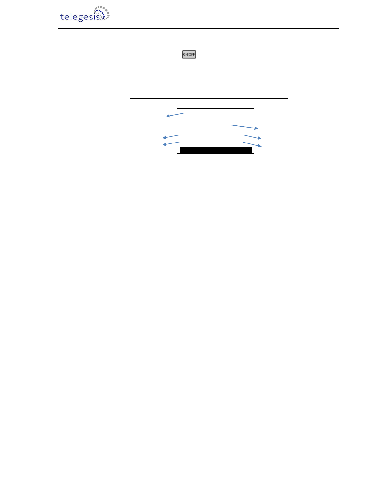
Start-up:
Upon pressing the power button for four seconds the following screen will be
displayed. This screen has useful information about the product such as the serial numbers of
device and the firmware version of HHT. This screen is only displayed upon power up.
Figure 5: Start-up Screen
TELEGESIS RANGE FINDER
Press Any Key
a
HHT
2.4GHz ZigBee
Network Surveyor
IHD
: xxx
: xxx
VER
GAS
: xxx
: xxx
c
d
b
f
e
(a) Product Name
(b) Space for OEM Label
(c) Serial Number of the HHT
(d) Serial Number of SAT-A set to emulate IHD
(e) Serial Number of SAT-B set to emulate GAS
(f) Device Firmware version.
Telegesis ZigBee RangeFinder
©2012 Telegesis (UK) Ltd -11- Telegesis ZigBee RangeFinder
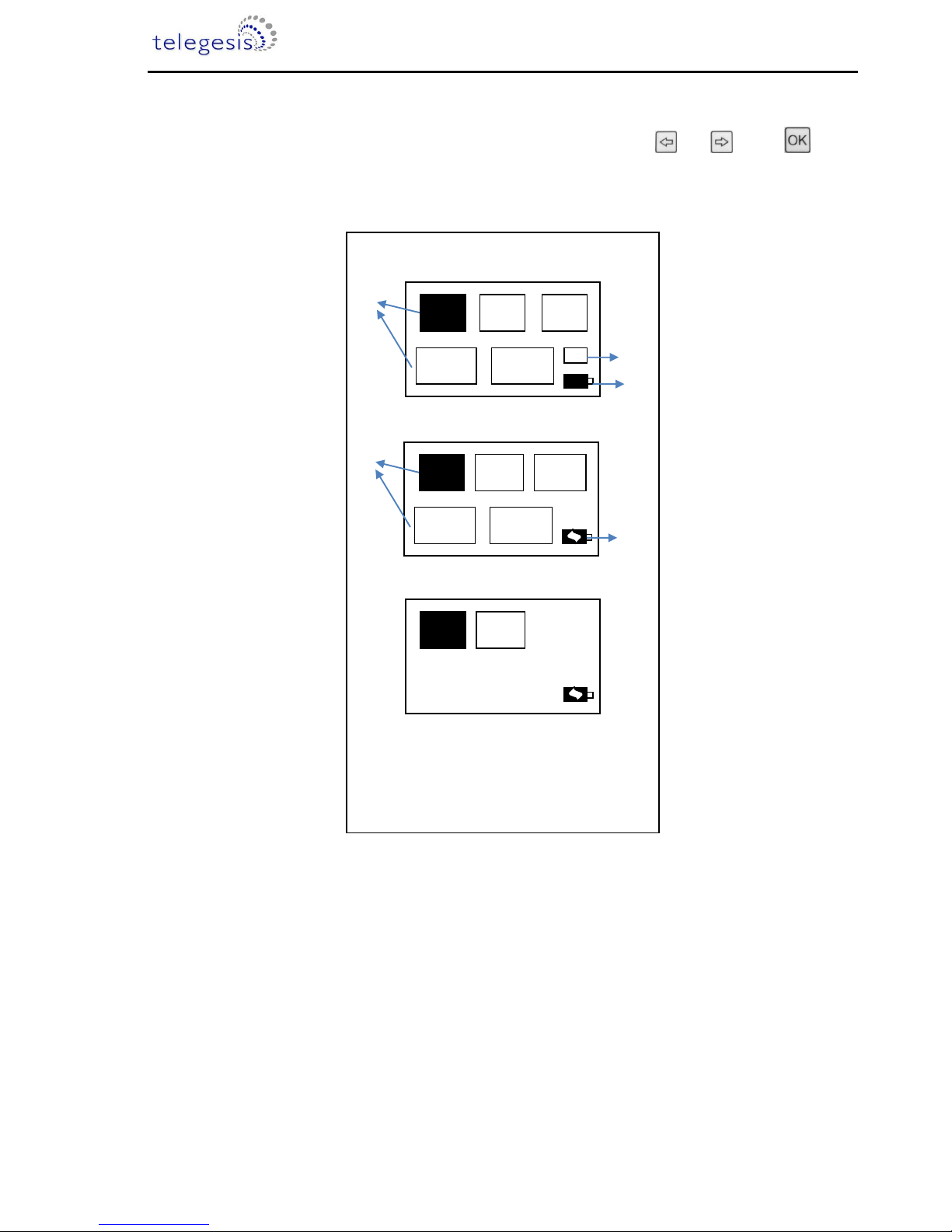
Menu Screens:
Menu items can be scrolled through using the navigations keys and Press button
to enter the selected menu item. The battery symbol shows the current battery status.
Figure 6: Start-up Screen
(a) Menu Items
(b) Single SAT / Dual SAT option
(c) Battery status
(d) Battery charging
a
a
b
c
PreTest
TestA Test B Energy
Scan
Config
IG
Menu Screen 1
d
Tx
Tone
Ch
Ping
Ch
E-Scan
FW
Upgrades
Data
Logger
Menu Screen 2
One
Hop
Device
Info
Menu Screen 3
Telegesis ZigBee RangeFinder
©2012 Telegesis (UK) Ltd -12- Telegesis ZigBee RangeFinder
Normal Test Modes:
Pre-Test:
A Pre-Test is required before the ‘Test A’ or ‘Test B’ can be performed. The Pre-Test has the
function of sanity checking the link between the HHT and the SAT units. Also performing Pre-Test
will configure the current test settings in SAT units. A test carried out without running a Pre-Test
may NOT present valid results. Any change in the Configuration settings should be followed by a
Pre-Test.
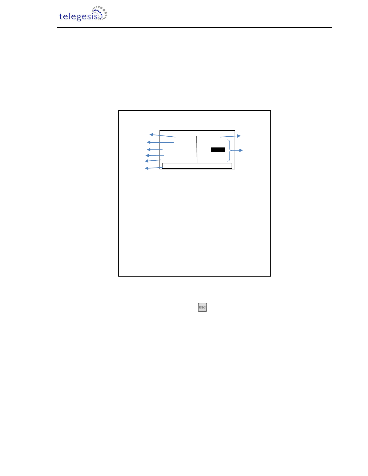
Figure 7: Pre-Test Screen
The completion of the Pre-Test is indicated by a short beep from the built-in buzzer. To return to the
main menu from the Pre-Test Screen please press
(a) Label of the first Satellite unit IHD
(b) Serial number of Satellite Labelled IHD
(c) Status of Pre-Test, OK for Success and NOK for Failure
indicated by Red backlight
(d) Battery status of the IHD unit in percentage from 0 to 100%
(e) RSSI of the received data during Pre-Test
(f) HHT information
i. Channel used for Pre-Test
ii. Power output level for Pre-Test
iii. Battery status of HHT
(g) Label of second Satellite unit GAS
(h) Information as listed in (b) to (e) relating to second Satellite Unit
GAS
a
h
g
IHD
GAS
65534
Link
IHD
RSSI
: OK
: 4%
65535
: -20
: -20
RSSI
IHD
Link
: 4%
: NOK
Ch: 11 Pw:8dBm Bat:100%
b
e
c
d
f
Pre-Test Screen
Telegesis ZigBee RangeFinder
©2012 Telegesis (UK) Ltd -13- Telegesis ZigBee RangeFinder
Test A / Test B:
Telegesis Range Finder tests are designed to evaluate the suitability of deployment of a
Smart Energy device which is why they focus on the ZigBee Smart Energy recommended RF
channels in the 2.4GHz spectrum. Tests A and B are performed on ZigBee SE channels 11, 14, 15
and 19 during Test-A, while the remaining of SE channels 20, 24 and 25 are tested in Test-B.
Although the Rangefinder is designed to assist with ZSE installations, the Continuous test
and Energy scan can be used to analyse the entire ZigBee 2.4GHz spectrum.
At the start of each test-A/B, countdown is activated to give a chance for the operator to
put the HHT in place of simulated test device such as electricity meter and move away from the
meter housing if necessary. This timer is configurable in the Configuration Menu.
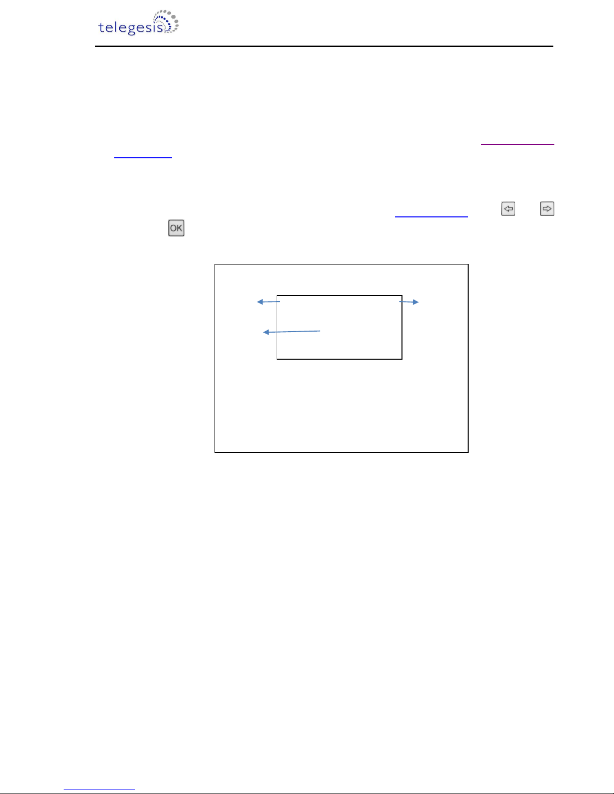
To perform tests A or B, navigate to the menu item on Menu Screen 1 using and
keys and press button for the test start screen to appear. Continuous and
Figure 8: Test Start Screen
Once the countdown has elapsed, the test starts and the test results are displayed for each
channel for the test as the test progresses. The completion of the test is indicated by a short beep
from the built-in buzzer. The display backlight changes to Red for test failure and to Blue colour if
the test is a pass. Also the failed values will be inverted. For details of the Pass/Fail criteria please
see section “Interpreting Test Results”.
(a) Name of the test about to run (Test A in this case)
(b) Countdown, the default value of the countdown is 5
seconds which can be changed through Config menu
(c) Transmit power for the test
a
c
Test A
Tx:8dBm
b
Time to Start
02
Test Start Screen
 Loading...