

Page 1
Telegesis (UK) Limited
TG-ETRX1-PM-01-106 1
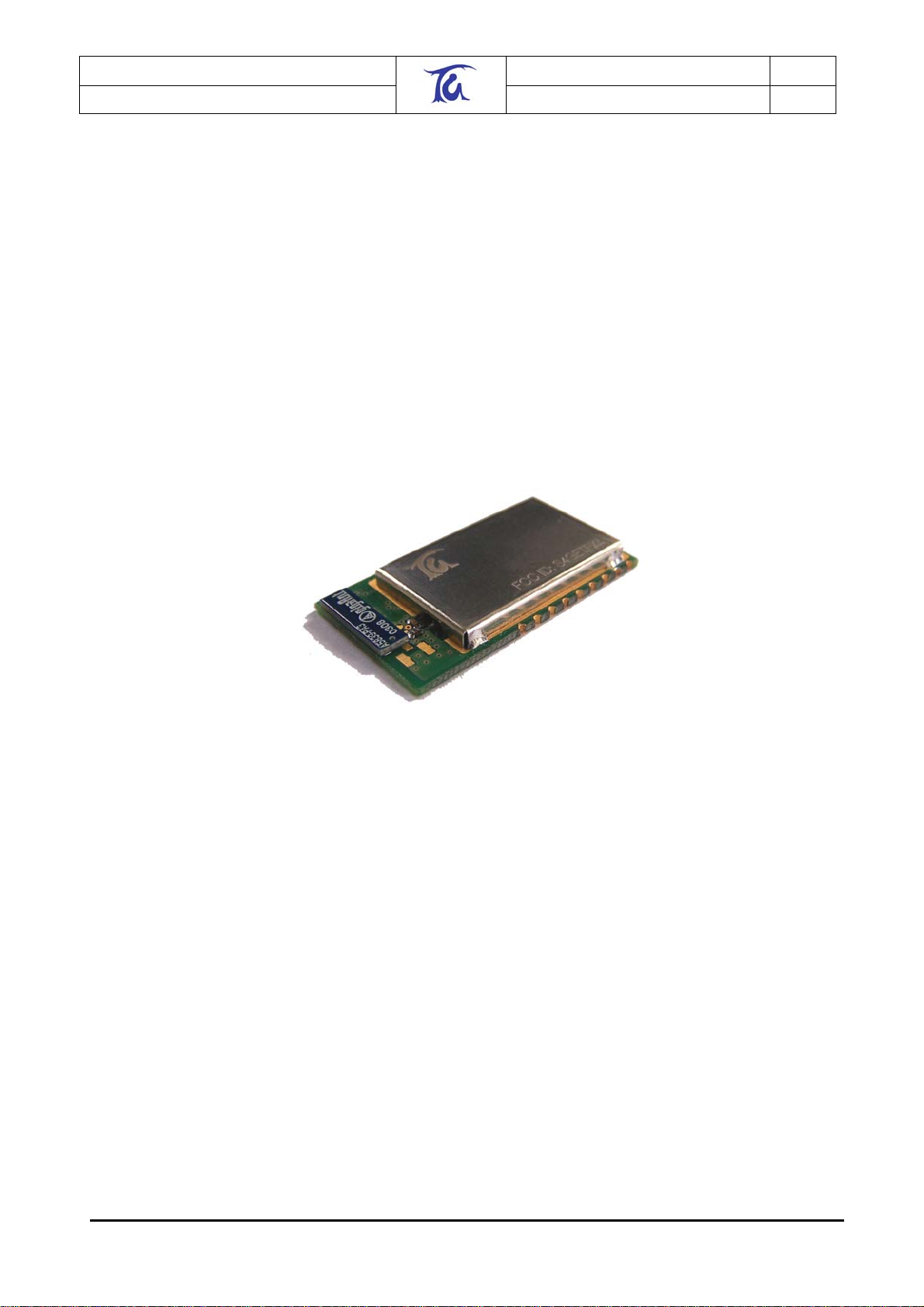
ETRX1
Preliminary Product Manual 1.06
TG-ETRX1-PM-01-106
ETRX1 (ZIGBEE™ READY) MODULE
PRODUCT MANUAL
Telegesis
©2005 Telegesis (UK) Ltd ETRX1 Product Manual (Rev 1.06)
Page 2

Telegesis (UK) Limited
TG-ETRX1-PM-01-106 2
ETRX1
Preliminary Product Manual 1.06
Table of Contents
1. INTRODUCTION..........................................................................................................3
2. ETRX1 FUNCTION SUMMARY ..................................................................................4
3. PRODUCT APPROVALS............................................................................................5
3.1. CE & FCC Approvals ................................................................................................ 5
3.2. IEEE 802.15.4........................................................................................................... 5
3.3. The ZigBee™ Protocol.............................................................................................. 5
4. FREQUENTLY ASKED QUESTIONS.........................................................................6
5. ABSOLUTE MAXIMUM RATINGS..............................................................................8
6. OPERATING CONDITIONS ........................................................................................8
7. ELECTRICAL SPECIFICATIONS ...............................................................................9
8. FUNCTIONAL DESCRIPTION ..................................................................................10
8.1. Device Pin-out ......................................................................................................... 11
8.2. Firmware Description .............................................................................................. 12
8.2.1. Custom Firmware.................................................................................................... 12
8.3. Interface Description............................................................................................... 13
9. AT STYLE COMMAND CONVENTIONS ..................................................................14
9.1. Using parameters.................................................................................................... 14
9.2. AT Command Syntax.............................................................................................. 15
9.2.1. Module Control & Configuration Commands ..........................................................16
9.2.2. Communication Commands.................................................................................... 20
9.2.3. I/O Commands........................................................................................................ 30
10. S-REGISTERS...........................................................................................................31
10.1. Standard S-Registers.............................................................................................. 32
10.2. Extended S-Registers ............................................................................................. 36
11. LIST OF ERROR CODES..........................................................................................40
12. PHYSICAL DIMENSIONS .........................................................................................41
13. RECOMMENDED FOOTPRINT ................................................................................42
14. ORDERING INFORMATION .....................................................................................43
15. TRADEMARKS..........................................................................................................44
16. DISCLAIMER.............................................................................................................44
17. CONTACT INFORMATION .......................................................................................44
18. REFERENCES...........................................................................................................44
©2005 Telegesis (UK) Ltd ETRX1 Product Manual (Rev 1.06)
Page 3

Telegesis (UK) Limited
TG-ETRX1-PM-01-106 3
ETRX1
Preliminary Product Manual 1.06
1. Introduction
This document describes the Telegesis ETRX1 wireless meshing Module which has been
designed to be integrated into another device and to provide a fast, simple and low cost (ZigBee
compatible with adoption of the EmberZstack) interface.
The Telegesis ETRX1 Module has been designed to be built into any device and provide a low
cost low power radio, ZigBee™ ready meshing solution, using the Ember technologies EmberNet
stack. Integration into a wide range of applications is made easy using a simple AT style software
interface and advanced hardware design.
No RF experience or expertise is required to add this powerful wireless networking capability to
your products. The ETRX1 offers fast integration opportunities and the shortest possible time to
market for your product.
©2005 Telegesis (UK) Ltd ETRX1 Product Manual (Rev 1.06)
Page 4
Telegesis (UK) Limited
A
TG-ETRX1-PM-01-106 4
ETRX1
Preliminary Product Manual 1.06
2. ETRX1 Function Summary
The Telegesis ETRX1 has been designed to be built into any device and
provide a low cost, low power, ZigBee™ ready meshing solution, using the
proven EmberNet technology. No RF experience or expertise is required
to add this powerful wireless networking capability to your products. The
ETRX1 offers fast integration opportunities and the shortest possible time
to market for your product. The AT style command line interface allows
the adopter to quickly integrate meshing radio technology into any product
without the need for complex programming or RF design work.
Module Features
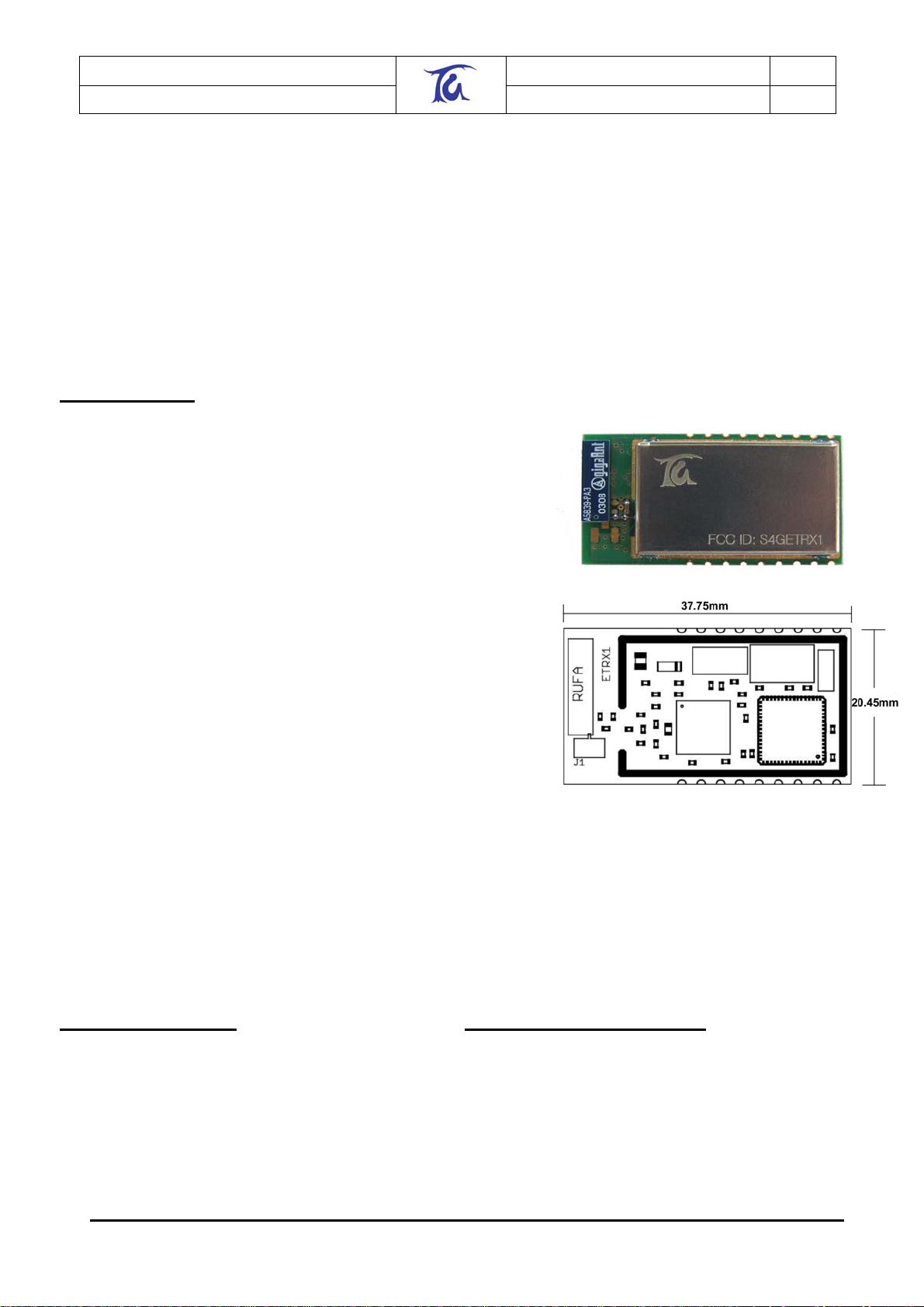
• Small form factor, SMT module 37.75mm x 20.45mm x
3.4mm
• Optional board to board or board to cable plug-in connector
• Integrated antenna or alternative Hirose U.FL antenna
connector
• UART interface for easy communication
• IEEE 802.15.4 compliant
• Can act as FFD, RFD and Coordinator
• Hosts the Atmel Atmega 128L and the Ember EM2420
• 128k flash, 4kbytes EEPROM and 4kbytes of RAM
• Up to 8 MIPS processing power
• Module comes with standard Telegesis AT style software
interface.
lso available without Telegesis AT style interface or with
•
customer specific firmware
• 8 general purpose I/O lines and 2 analogue inputs
• In System programmable
• Optional JTAG Support
• Supports 5 different power down modes
• Based on the proven EmberNet classic Stack
• Full ZigBee™ compliance will be available with the upcoming
EmberZNet stack
• Firmware upgrades via RS232 or over the air (password
protected)
• Hardware supported encryption (AES-128)
• Supply voltage 2.7V – 3.6V
• Current Consumption as low as 15uA in sleep mode
• Tested for CE and FCC compliance (with integrated
antenna)
• Operating temperature range -20
0
C to +650C
Development Support
• A Development Kit is available with a
development board with RS232 connectivity
and I/O break-outs
• For high volume customers the AT style
software interface command dictionary can be
extended
• Custom software development can be provided
on request
Example AT-Style Commands
• AT+SN Search network & discover
devices
• AT+BCAST Sends a Broadcast
• AT+UCAST:<address> Sends a Unicast
• AT+ASS:<address> Associate Node
At Power-up the last configuration is loaded from EEPROM.
This can eliminate the need for an additional Host
Controller.
©2005 Telegesis (UK) Ltd ETRX1 Product Manual (Rev 1.06)
Suggested Applications
• AMR – Automatic Meter Reading
• Wireless Alarm and Security
• Home/Building Automation
• Wireless sensor Networks
• Industrial Control
• ZigBee™ systems
• PC Peripherals
• IEEE 802.15.4 systems
Radio Features
• Based on the Ember EM2420, 2.4GHz
ISM Band.
• Direct Sequence Spread Spectrum RF
transceiver (DSSS)
• 250kbit/s effective data rate
• Very Low Power ( – 30mA in Rx)
• 16 channels (802.15.4 Channel 11 to 26)
• Up to –1dBm output power
Page 5

Telegesis (UK) Limited
TG-ETRX1-PM-01-106 5
ETRX1
Preliminary Product Manual 1.06
3. Product Approvals
3.1. CE & FCC Approvals
The ETRX1 has been designed to meet all national regulations for World-wide use. It has been
tested and approved by a certified laboratory for RF Transmission, EMC and for general product
safety.
Using the integrated Antenna it conforms with EN300 440 (Europe) and FCC CFR 47 Part 15
(USA).
This device complies with Part 15 of the FCC rules. Operation is subject to the following
two conditions: (1) this device may not cause harmful interference, and (2) this device must
accept any interference received, including interference that may cause undesired
operation.
FCC ID: S4GETRX1
Please Note:
The ETRX1 device carries FCC authorization and is marked with the FCC ID Number. Whilst any
device into which this authorized module is installed will not normally be required to obtain FCC
authorization, this does not preclude the possibility that some other form of authorization or testing
may be required for the finished device.
When the ETRX1 module is integrated inside another device/product, then the outside surface of
that device/product must display a label referring to the enclosed module. This exterior label can
use wording such as “Contains Transmitter Module FCC ID: S4GETRX1” or “Contains FCC ID:
S4GETRX1” although any similar wording that expresses the same meaning may be used.
This module complies with the USA SAR requirements and is not intended to be operated with in
20cm of the body.
3.2. IEEE 802.15.4
IEEE 802.15.4 is a standard for low data rate wireless networks (typically data rates of 250 kbps,
40 kbps, and 20 kbps) which focuses on low cost, low duty cycle, long primary battery life
applications as well as mains-powered applications. It is the basis for the open ZigBee™ Protocol.
3.3. The ZigBee™ Protocol
The ZigBee™ Protocol is a new set of standards for wireless connectivity between any devices
over short distances (100 metres). The specification was ratified in December 2004, paving the
way for companies to start making low-power networks a reality.
ZigBee™ uses an IEEE 802.15.4 radio specification running on the 2.4GHz band, plus three
additional layers for networking,
security, and applications. What makes the specification unique is
its use of a mesh network architecture which, in bucket chain style, passes data from one node to
the next until it lands at its endpoint.
©2005 Telegesis (UK) Ltd ETRX1 Product Manual (Rev 1.06)
Page 6

Telegesis (UK) Limited
TG-ETRX1-PM-01-106 6
ETRX1
Preliminary Product Manual 1.06
4. Frequently Asked Questions
• What is the ZigBee™ Alliance?
The ZigBee™ Alliance is an association of companies working together to enable reliable, costeffective, low-power, wirelessly networked, monitoring and control products based on an open
global standard.
The goal of the ZigBee™ Alliance is to provide the consumer with ultimate flexibility, mobility, and
ease of use by building wireless intelligence and capabilities into every day devices. ZigBee™
technology will be embedded in a wide range of products and applications across consumer,
commercial, industrial and government markets worldwide. For the first time, companies will have
a standards-based wireless platform optimised for the unique needs of remote monitoring and
control applications, including simplicity, reliability, low-cost and low-power.
• Why do we need ZigBee™ ?
Until The ZigBee™ Standard was ratified in December of 2004 there was no standard approach
that addressed the unique needs of most remote monitoring and control applications. The
ZigBee™ Standard enables the broad-based deployment of reliable wireless networks with low
complexity, low cost solutions and provides the ability for a product to run for years on inexpensive
primary batteries (for a typical monitoring application). It is also, of course, capable of
inexpensively supporting robust mesh networking technologies
• What is the EmberZNet Stack?
The Telegesis ETRX1 utilises the EmberNet/EmberZNet protocol stacks and can form a scalable,
self-organizing, self-healing wireless networking platform based on the ZigBee™ specifications.
The EmberZNet supports a variety of network topologies for wireless monitoring and control
applications, including mesh, star, and cluster tree. Applications running the EmberZNet stack can
be interoperable with other ZigBee™ nodes. EmberZNet provides all of the standard benefits that
come with ZigBee™ including: flexible topologies, high security, broad interoperability, low cost,
long battery life, and integrated network management. In addition, EmberZNet applications can
take advantage of the industrial strength reliability and unprecedented ease of use of the Ember
Transport Layer capabilities.
Until now, much of the cost of deploying sensing and control devices was in installing the network
to connect them. With EmberZNet, the value, like the network, is embedded in the devices
themselves. EmberZNet’s self-organizing, self-healing mesh algorithms produce networks that are
reliable, flexible, secure, and easy to use. Adding devices only makes EmberZNet sensing and
control networks stronger and more efficient. Designed from the ground up for developers of
sensing and control products, the EmberZNet product suite enables rapid development and
deployment of embedded wireless networks that virtually “see around corners,” and that have no
single point of failure.
The EmberZNet Protocol Stack is a compact, scalable implementation of the ZigBee
specifications which translates into lower cost MCU options for device manufacturers. The stack is
available in different configurations optimized for the various ZigBee node types; PAN
coordinators, full function devices, and reduced function devices. The stack is already available for
several microprocessor platforms supported by Ember.
©2005 Telegesis (UK) Ltd ETRX1 Product Manual (Rev 1.06)
Page 7

Telegesis (UK) Limited
TG-ETRX1-PM-01-106 7
ETRX1
Preliminary Product Manual 1.06
• Where would my application sit?
There are a number of options. When using the Telegesis AT style command interface the
application sits on a host microcontroller which is external to the ETRX1 Module. Additionally the
ETRX1 can be used stand-alone using the pre-defined functionality defined in the non volatile SRegisters. The S-Registers (shown in Section 10) are mostly non-volatile registers holding the
configuration data of the ETRX1 wireless meshing module. If you decide to develop your own
firmware instead of using the Telegesis “AT style” command interface then it can run on the Atmel
ATmega128L on the ETRX1 module.
• What do I need to start my development?
The quickest and easiest way to begin your development is to use a set of ETRX1DV development
kits, but if you wish you could integrate the ETRX1 onto your own carrier boards. To connect the
ETRX1 to a PC you will need to use an RS232 level converter or alternatively connect the ETRX1
straight to a host microcontroller.
©2005 Telegesis (UK) Ltd ETRX1 Product Manual (Rev 1.06)
Page 8

Telegesis (UK) Limited
TG-ETRX1-PM-01-106 8
ETRX1
Preliminary Product Manual 1.06
5. Absolute Maximum Ratings
Parameter Min. Max. Units Condition
Supply Voltage Vdd -0.3 3.6 V
Voltage on any pin -0.3 Vdd+0.3, max 3.6 V
Input RF level 10 dBm
Storage Temperature range -50 150 °C
Reflow Soldering Temperature 260 °C T=10s
Table 1: Absolute Maximum Ratings
The absolute maximum ratings given above should under no circumstances be violated.
Exceeding one or more of the limiting values may cause permanent damage to the device.
Caution! ESD sensitive device. Precautions should be used when handling the
device in order to prevent permanent damage.
6. Operating Conditions
Typical values at 3.3V 25°C.
Parameter Min. Typ. Max. Units Condition
Supply Voltage, Vdd 2.7 3.3 3.6 V
Supply Current
Operating ambient
temperature range
Table 2: Operating Conditions
30 mA TX –1dBm
22 mA TX – 10dBm
19 mA TX –20dBm
18 mA TX –30dBm
30 mA RX
10 mA Sleep Mode 1
3.3 mA Sleep Mode 2
4.2 mA Sleep Mode 3
4.2 mA Sleep Mode 4
15 uA Sleep Mode 5
-20 25 70 °C
©2005 Telegesis (UK) Ltd ETRX1 Product Manual (Rev 1.06)
Page 9
Telegesis (UK) Limited
TG-ETRX1-PM-01-106 9
ETRX1
Preliminary Product Manual 1.06
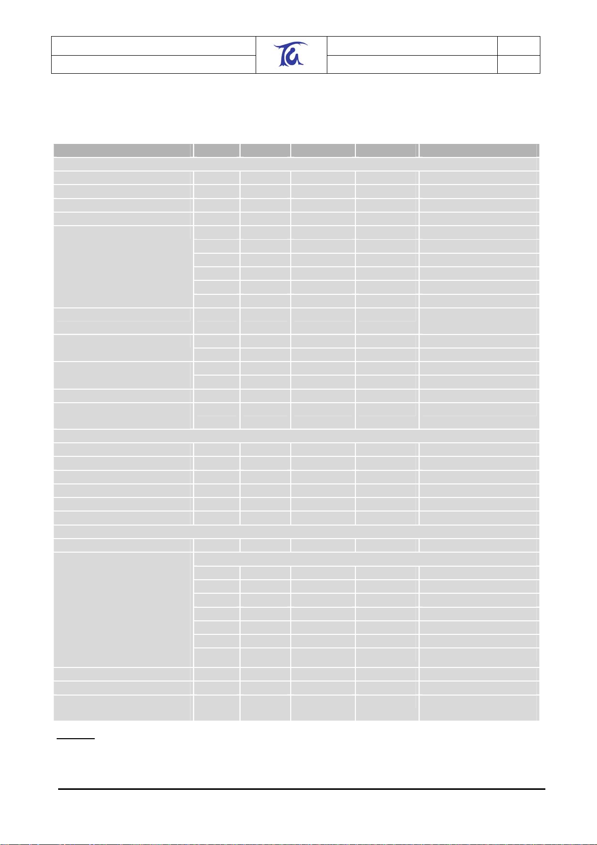
7. Electrical Specifications
Parameter Min. Typ. Max. Units Condition Radio Characteristics
Frequency Range 2.405 2.480 GHz
Adjustable output power -31 -1 dBm
Receiver sensitivity TBA dBm PER=1%
Channel Spacing 5 MHz
Spurious Emissions
Optimum load Impedance 50 Ω Using external
Rejection
Frequency error tolerance -300 300 kHz
Symbol rate error
tolerance
DC Characteristics
Input Low Voltage -0.5 0.2*V
Input High Voltage 0.6*V
Output Low Voltage 0.5 V VCC=3V I=10mA
Output High Voltage 2.4 V VCC=3V
IO Pin Pull-up Resistor 20 50 k Ω
ADC Input Resistance 55 100 M Ω
AC Characteristics
UART Baud Rate 1200 38400 38400 Bps
UART Error
1200
2400
4800
9600
14400
19200
28800
38400
ADC Conversion Time 2 µs
ADC Input Bandwidth 38.5 kHz
Special function Pin output
frequency
TBA dBm TX 30-1000MHz
TBA dBm TX 1-12.75GHz
TBA dBm TX 1.8-1.9Ghz
TBA dBm TX 5.15-5.3GHz
TBA dBm RX 0-1000MHz
TBA dBm RX 1-12.75GHz
Antenna
46 dB +5MHz Adjacent channel rejection
39 dB -5MHz
58 dB +10MHz Alternate Channel
55 dB -10MHz
120 ppm
V
CC
CC
VCC+0.5 V
0.2 %
0.2 %
0.2 %
0.2 %
-0.8 %
0.2 %
2.1 %
4MHz PWM available below
2MHz
Table 3: Electrical Specifications
©2005 Telegesis (UK) Ltd ETRX1 Product Manual (Rev 1.06)
Page 10
Telegesis (UK) Limited
TG-ETRX1-PM-01-106 10
ETRX1
Preliminary Product Manual 1.06
8. Functional Description
The Telegesis ETRX1 Module has been designed to be built into any device and provide a low
cost, low power, ZigBee™ ready meshing solution, using the Ember technologies EmberNet stack.
Integration into a wide range of applications is made easy using a simple AT style command
interface.
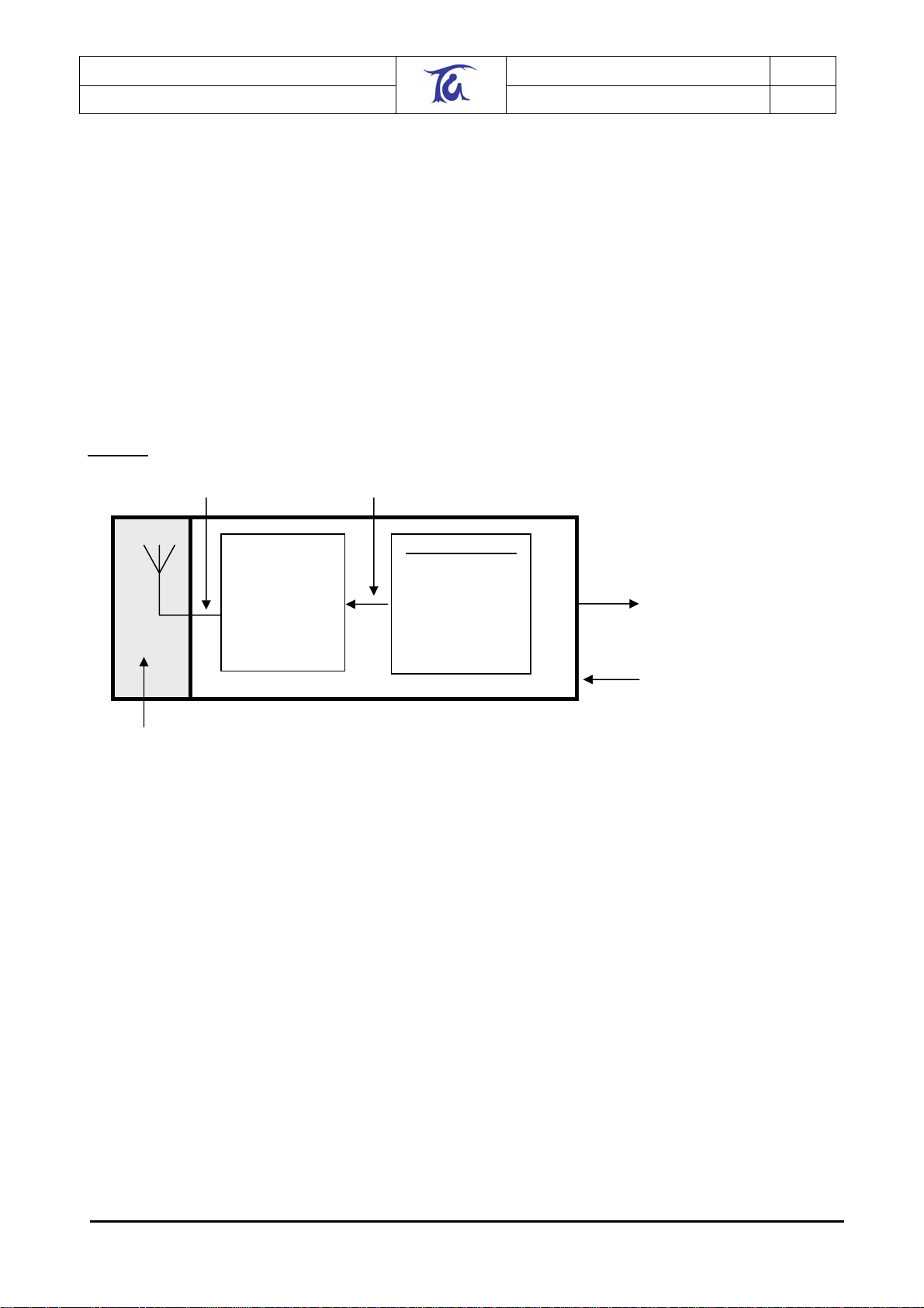
As shown in Figure 1, the module hosts the Ember EM2420 802.15.4 Transceiver and the Atmel
Atmega 128L. The flexible architecture also allows the module to be used for custom software
based on any existing or upcoming software stack.
The on-board antenna allows easy integration without the need for RF expertise. If required the
module can be supplied with a U.FL antenna connector to connect an external antenna.
Figure 1. Block Diagram
Balun Matching Circuit Data and Commands
Integrated Antenna or
optional Hirose U.FL
connector
The Atmel Atmega 128L is clocked at 8MHz delivering up to 8MIPS of processing power. For
timekeeping an additional 32.768kHz crystal is used. The microcontroller can be programmed in
circuit using an in-circuit programmer. Alternatively the pre-programmed boot-loader can be used
to upgrade the firmware via the UART or over the air. Note that in circuit programming using a
programmer will erase the boot-loader.
The EM 2420 transceiver uses Direct Sequence Spread Spectrum (DSSS) with 2 Mchip/s chip rate
giving a raw data rate of 250k/bits. The modulation format is Offset Quadrature Phase Shift
Keying (O-QPSK). The DSSS makes the communication link robust in noisy environments when
sharing the same frequency band with other applications.
For full details on the Ember EM2420 2.4GHz transceiver and the Atmel Atmega 128L please
consult the respective data sheets.
The use of RF frequencies and maximum allowed RF power is limited by national regulations. The
ETRX1 complies with the applicable regulations for the world-wide 2.45GHz ISM band. For full
details please see Section 3 on Product Approvals.
Ember EM2420
IEEE 802.15.4 RF
Transceiver
Atmel Atmega 128
Bootloader
AT-Command
Interpreter
EmberNet Stack
IEEE 802.15.4
8x Digital I/O
2 x Analogue Inputs
UART Interface
ISP
PWM
Optional JTAG
2.7 – 3.6 V
©2005 Telegesis (UK) Ltd ETRX1 Product Manual (Rev 1.06)
Page 11
Telegesis (UK) Limited
TG-ETRX1-PM-01-106 11
ETRX1
Preliminary Product Manual 1.06
8.1. Device Pin-out
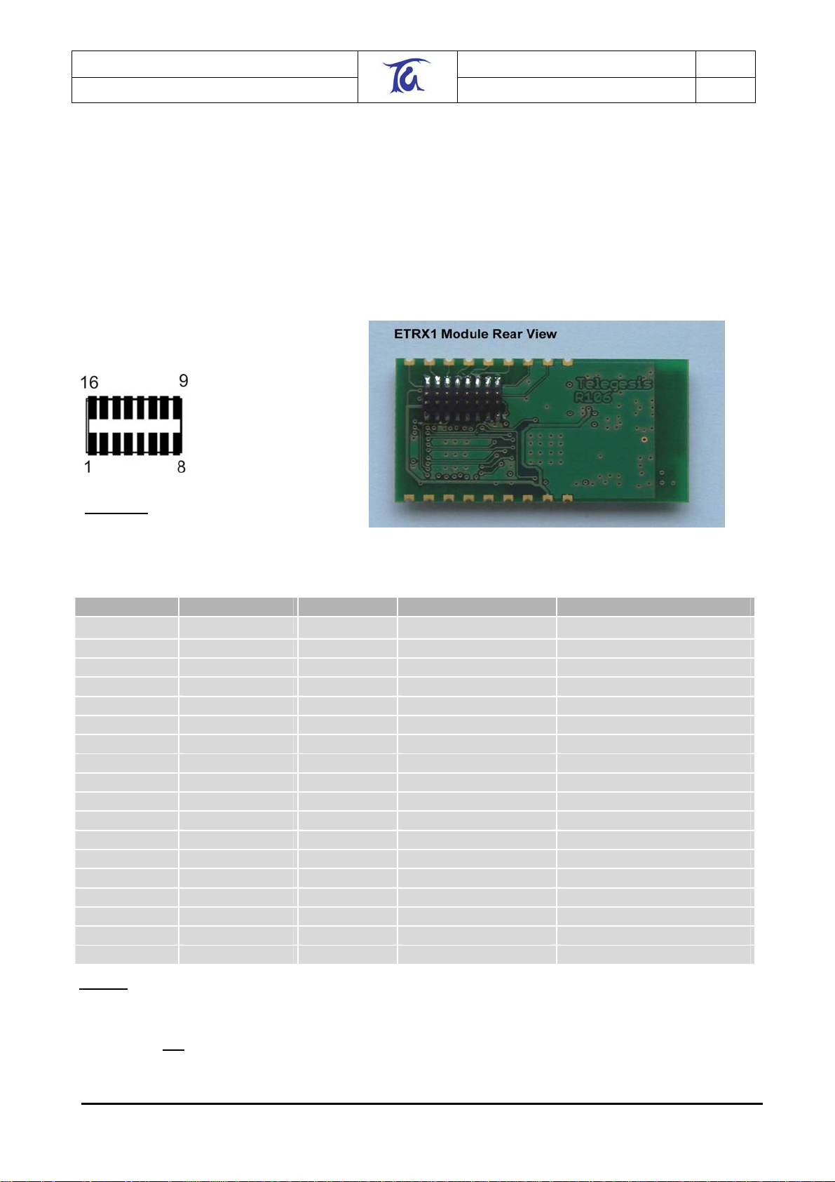
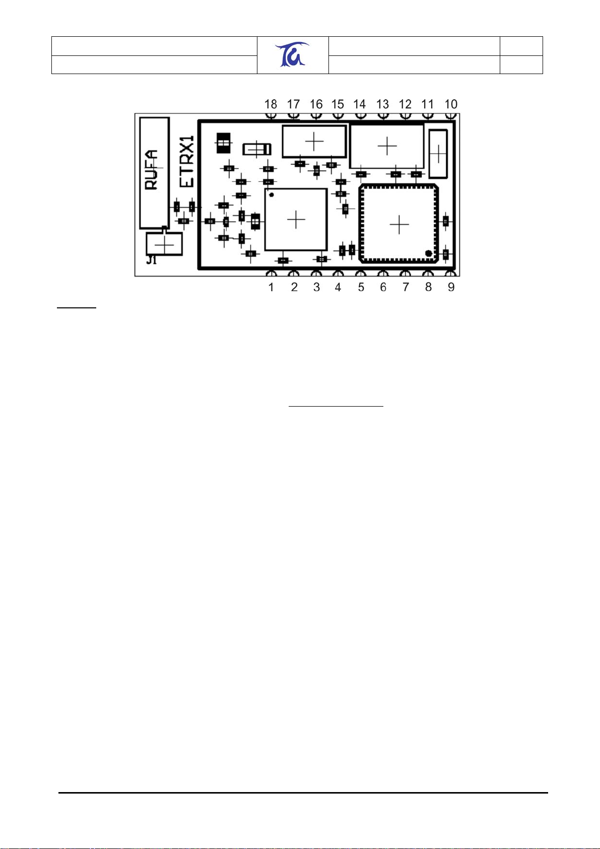
There are two ways of interfacing with the ETRX1 module. Firstly, the module can be surface
mounted using the 18 pads situated on the edges of the module. Secondly, a 2x8, 1.27mm pitch
surface mount header (included) can be attached to the bottom of the board to allow a plug-in
solution. The latter is ideally suited for applications where the radio needs to be retrofitted as an
upgrade in the field.
Table 4. Gives an overview of the pin-out and its functionality.
Figure 2: Pin configuration of Socket
The pin configuration shown in Figure 2 is valid when looking down onto the Socket of the
carrier PCB (i.e. devboard) with pin 1 facing towards the Antenna of the ETRX1.
Corner Pad Connector Pin Name Functionality ATMEGA Pin
1 1 GND GND GND
2 8 V
CC
3 1 GND GND GND
4 2 A/D1 A/D JTAG
5 3 A/D2 A/D JTAG
6 4 I/O7 I/O JTAG
7 5 I/O6 I/O JTAG
8 6 I/O5 I/O ISP PE1 (TXD0/PDO)
9 7 I/O4 I/O ISP PE0 (RXD/PDI)
10 9 SCK ISP
11 10 I/O3 I/O PB4 (OC0)
12 11 I/O2 I/O SFPIN PB7 (OC2/OC1C)
13 12 RESET Reset Reset
14 13 I/O1 I/O INT1 TWI
15 14 I/O0 I/O INT0 TWI
16 16 TXD TXD PD3 (TXD1/INT3)
17 15 RXD RXD PD2 (RXD1/INT2)
18 1 GND GND GND
V
CC
1
1
1
1
2
3
3
V
CC
PF7 (ADC7/TDI)
PF6 (ADC6/TDO)
PF5 (ADC5/TMS)
PF4 (ADC4/TCK)
PB1 (SCK)
PD1 (SDA/INT1)
PD0 (SCL/INT0)
Table 4: Pin Configuration
1
By default JTAG is disabled. Enabling JTAG functionality will sacrifice A/D1, A/D2 as well as I/O7
and I/O6.
2
SCK must not be used for any other purpose than in-system programming!
3
The TWI (Two wire interface) is not supported by the current firmware release, but can be used
with custom specific firmware.
©2005 Telegesis (UK) Ltd ETRX1 Product Manual (Rev 1.06)
Page 12
Telegesis (UK) Limited
TG-ETRX1-PM-01-106 12
ETRX1
Preliminary Product Manual 1.06
Figure 3: Pin Configuration of the corner pads
8.2. Firmware Description
The modules are pre-loaded with the Ember bootloader which supports over-the-air bootloading as
well as serial bootloading of new firmware. The modules also contain the current release of the
Telegesis AT style command interface. Check
Each module comes with a unique 64 bit 802.15.4 identifier which is stored in EEPROM.
The default AT-style command interface firmware is based on the EmberNet classic stack which
implements a full function device (FFD). The AT style command line interpreter has been
developed by Telegesis to allow easy access to the low level functionality.
The module is able to act as a PAN coordinator through external host control. The AT style
command line supplies all the tools required to set up and manage mesh and star topologies or a
mixture of both.
Using the command line interface RFD or leaf devices are emulated by using the EmberNet classic
stack with the routing features disabled. This allows them to go to sleep as they have no routing
responsibilities in the network. The ETRX1 uses the full functionality stack, rather than the
EmberNet Leaf Stack for RFD’s and leaf nodes to overcome some of the routing restraints of
classic leaf nodes whilst still allowing them to save power being asleep.
The firmware allows low level access to physical parameters such as channel and power level.
Parameters which define the functionality of the ETRX1 module and also allow standalone
functionality are saved in non volatile EEPROM organised in so called S-Registers.
The TWI (Two wire interface) is not supported by the current firmware release, but can be used
with custom firmware.
www.telegesis.com for updates.
8.2.1. Custom Firmware
For high volume customers the firmware can be customised on request.
©2005 Telegesis (UK) Ltd ETRX1 Product Manual (Rev 1.06)
Page 13

Telegesis (UK) Limited
TG-ETRX1-PM-01-106 13
ETRX1
Preliminary Product Manual 1.06
8.3. Interface Description
ADC
The module has two analogue inputs A/D1 and A/D2. Readings with reference to Vcc can be
made locally as well as remotely.
I/O
Pins I/O7 down to I/O0 are bi-directional I/O ports which can be controlled locally as well as
remotely by accessing local as well as remote S-registers. Although they are on different ports of
the microcontroller they can be controlled using three single 8 bit registers representing the data
direction, the output buffer and the input buffer.
ISP
Pins I/O5, I/O4, SCK and reset can be used to in-circuit program the module if required.
Reprogramming the flash of the microcontroller will delete the bootloader.
UART
Via the TXD and RXD pins the AT style command interpreter can be accessed. The ETRX1 can
buffer up to 128 bytes of incoming data in a software FIFO buffer and uses XON/XOFF flow
control. See the datasheet of the Atmel Atmega 128L for more information about the build-in
UART.
Interrupt
Level changes on pins I/O0 and I/O1 will cause an interrupt to the module if defined as input in the
corresponding data direction register.
Reset
Pulling the reset pin low will cause the module to restart. A external pull-up is not required.
PWM
I/O4 can alternatively act as a special function pin which can generate clocks up to 4MHZ or act as
a PWM. This functionality can be controlled locally as well as remotely by accessing local as well
as remote S-registers.
Antenna
Matching is provided to match the radio to the integrated antenna or to an optional external general
purpose 2.4GHz antenna. The internal Rufa antenna is supplied by GigaAnt. For full data on the
Rufa antenna please refer to the gigaAnt Rufa data sheet,
Power
The module is able to operate from 3.6V down to 2.7V which makes it ideally suited for battery
powered applications.
www.gigaant.com.
©2005 Telegesis (UK) Ltd ETRX1 Product Manual (Rev 1.06)
Page 14

Telegesis (UK) Limited
TG-ETRX1-PM-01-106 14
ETRX1
Preliminary Product Manual 1.06
9. AT Style Command Conventions
To simplify the communication with the ETRX1 module an AT command set, similar to the industry
standard Hayes modem control language, is used.
Each command must be preceded by the "AT" or "at" prefix. To terminate a command line enter
<CR>. Any data not following this pattern is either not accepted by the module or will cause an
error message in response. Also, a mix of upper and lower case letters like “At+BloAd” will not be
accepted. Commands need to be issued either completely in upper case or completely in lower
case characters.
Commands are followed by a response that includes .<CR><LF><response><CR><LF>. Any data
which is prompted to the user is delivered in the format <prompt><CR><LF>. Prompts may
appear whenever the corresponding event occurs. A prompt intersecting a command being
entered will not affect the command itself.
Throughout this document, only the responses are presented, <CR><LF> are omitted intentionally.
It is recommended to wait for a response before issuing the next command. Also sequences of AT
commands in a single line are not supported.
The ETRX1 features a 128 byte receive FIFO to buffer incoming characters. To prevent a buffer
overflow caused by incoming data in excess of 128 bytes XON/XOFF handshaking is used.
Read Command
AT+XXX?
Write Command
AT+XXX=<…>
Execution Command
AT+XXX
Commands ending with a ‘?’ return the currently
set value of the parameter or parameters
This command sets user-definable parameters as
indicated by the ‘=’ sign.
This command executes routines of the module
and returns parameters
Table 5: Types of AT commands and responses
9.1. Using parameters
There are no default or optional parameter sets, so each parameter must be entered in the correct
format.
<XX>
n, <n>
S
C
<errorcode>
<EUI64>
©2005 Telegesis (UK) Ltd ETRX1 Product Manual (Rev 1.06)
8 bit hexadecimal number. Valid characters are 09, a-f and A-F.
Number from 0-9
Sign
character
8 bit hexadecimal error code as explained in 11.
32 bit 802.15.4 address in hexadecimal e.g.
0123456789ABCDEF
Page 15

Telegesis (UK) Limited
TG-ETRX1-PM-01-106 15
ETRX1
Preliminary Product Manual 1.06
Table 6: Different formats of parameters
9.2. AT Command Syntax
The AT commands can be divided into the three following sections, namely module control &
configuration commands, communication commands and I/O commands. The following table
gives a quick reference of all commands available.
Command Overview
ATZ Software Reset
AT&F
AT+REMZ
ATI
AT+BLOAD
AT+CLONE
AT+TEST
ATSn
AT+PDWN
AT+BTABLE
AT+COO
AT+ESCAN
AT+SN
AT+EN
AT+SORPHAN
AT+EBN
AT+SNEIGHBOURS
AT+PING
AT+ASS
AT+ASACK
AT+DASSR
AT+DASSL
AT+BCAST
AT+UCAST
AT+CCAST
AT+COST
AT+OPCHAN
AT+ACKCHAN
+++
AT+SREMn
AT+TOKDUMP
AT+ADLOC
AT+ADREM
AT+IDENT
Restore Factory Settings
Reset Remote Node
Display Product Identification Information
Enter the Bootloader Menu
Clone Local Node to Remote Node
Run Self Test
S-Register Access
Power Control
Display the Devices Binding Table
Display the Devices Coordinator
Scan the Energy of the Current Channel
Scan Network for other Nodes
Establish PANetwork
Scan for Orphans
Establish PANetwork using Beacons
Scan for Neighbours
Indicate Presence in the Network
Associate Node
Accept Association Request from Coordinator
Disassociate Remote device from PAN
Disassociate Local device from PAN
Transmit a Broadcast
Transmit a Unicast
Transmit a Unicast to the Coordinator
Cost to Talk to Remote Node
Open a Channel to a Remote Node
Accept Channel
Close Channel
Remote S-Register Access
Display all local S-Registers
Request a Reading from the Local A/D Converter
Request a Reading from a Remote A/D Converter
Play a Tune on Remote Devboard
Table 7: Command Overview
©2005 Telegesis (UK) Ltd ETRX1 Product Manual (Rev 1.06)
Page 16

Telegesis (UK) Limited
TG-ETRX1-PM-01-106 16
ETRX1
9.2.1. Module Control & Configuration Commands
Z – Software Reset
Execute Command
ATZ
SW release
&F – Restore Factory Defaults
Execute Command
AT&F
SW release
+REMZ – Reset Remote Node
Execute Command
AT+REMZ:<EUI64>
Use on:
Coordinator
FFD’s
RFD’s
SW release
I – Display Product Identification Information
Execute Command
ATI
Response
Module Performs a software reset
All S Registers keep the user defined values
R100
Response
Module Performs a software reset
All non volatile S Registers are updated with the
factory defaults
R100
Response
OK
or
ERROR<errorcode>
<errorcode> represents the error code explained
in section 11. On receiving this command the
remote node will soft reset itself. Note: If the
remote node is an FFD, packets which are
currently relayed by this node may get lost.
R103
Response
TELEGESIS
Ryyy
Preliminary Product Manual 1.06
<EUI64>
OK
Where yyy is the software revision and <EUI64> is
the IEEE 802.15.4 identifier
SW release
R100
©2005 Telegesis (UK) Ltd ETRX1 Product Manual (Rev 1.06)
Page 17

Telegesis (UK) Limited
TG-ETRX1-PM-01-106 17
ETRX1
+BLOAD – Enter the bootloader menu
Execute Command
AT+BLOAD
Response
<entering bootloader>
The device leaves the AT command line and
enters the Ember bootloader menu for
downloading new firmware.
Please note that the bootloader menu will run at a
data rate of 38k4, no parity, 8 data bits regardless
of the current data rate and the S3 register setting.
SW release
R100
+CLONE – Clone Local node to remote node
Execute Command
AT+CLONE:<EUI64>,cccccccc
Use on:
Coordinator
FFD’s
RFD’s
Response
Cloning…
or
ERROR<errorcode>
Where <errorcode> represents the error code
explained in section 11.
Clones the firmware of the local node to a remote
node which address is given by <EUI64>.
cccccccc represents the remote nodes 8 digit
cloning protection password. After completion a
soft reset is caused on both ends.
SW release
R100
+TEST – Run self test
Execute Command
AT+TEST
Module Performs a self test in order to check
for hardware problems
Note: If JTAG is activated by programming
the appropriate fuses of the Atmega128, the
self test will display an error message which
Response
OK
Or if any problems occur
ERROR<errorcode>
Where <errorcode> represents the error code
explained in section 11.
can be ignored.
SW release
R100
Preliminary Product Manual 1.06
©2005 Telegesis (UK) Ltd ETRX1 Product Manual (Rev 1.06)
Page 18

Telegesis (UK) Limited
TG-ETRX1-PM-01-106 18
ETRX1
Preliminary Product Manual 1.06
Sn – S-Register access
Read Command
ATSn?
Response
<data>
OK or ERROR<errorcode>
The module displays the contents of S-register n or
an error message, where <errorcode> represents
the error code explained in section 11.
Write Command
ATSn=<data>
Response
OK or ERROR<errorcode>
The data is written to S-register number n and if
applicable stored in non volatile EEPROM. The
data format for each individual S Register is given
in the S-Register description.
<errorcode> represents the error code explained in
section 11.
SW release
R100
+PDWN – Power control
Read Command
AT+PDWN?
Response
+PDWN:<N>
OK
Write Command
AT+PDWN=<n>
Response
OK or ERROR<errorcode>
Where <errorcode> represents the error code
explained in section 11.
Parameter
<n>
0. Module awake
1. Transceiver Power down, processor
active
2. Transceiver Power Down, processor
runs on reduced clock rate, RS232
baudrate goes down to 4800bps
3. Module power down, complete wakeup
by UART or external interrupt (falling
edge on I/O0 or I/O1)
4. Module power down, wakeup into
mode 1 by UART or external interrupt
(falling edge on I/O0 or I/O1)
5. Module Power Down complete wakeup
by external interrupt or reset only
The default Power mode after reset is defined by
register SA.
SW release
R100
©2005 Telegesis (UK) Ltd ETRX1 Product Manual (Rev 1.06)
Page 19

Telegesis (UK) Limited
TG-ETRX1-PM-01-106 19
ETRX1
+BTABLE – Display the devices binding table
Read Command
AT+BTABLE?
Response
<BINDING TABLE>
OK or ERROR<errorcode>
<errorcode> represents the error code explained in
section 11. The binding table can be displayed for
debugging purposes. It lists all nodes registered
with the local node. The first entry (if used)
represents the binding to the co-ordinator and the
last entry is the multicast ID.
SW release
R100
+COO – Display the devices Coordinator
Read Command
AT+COO?
Use on:
Coordinator
FFD’s
RFD’s
Response
+COO:NONE
or
+COO:<EUI64>
followed by
OK or ERROR<errorcode>
<errorcode> represents the error code explained in
section 11. <EUI64> id the address of the
coordinator. In case the device is not associated to
a PAN the result is “none”.
SW release
R100
+ESCAN – Scan the energy of the current channel
Read Command
AT+ESCAN?
Use on:
Coordinator
FFD’s
RFD’s
Response
+ESCAN:XX
OK or ERROR<errorcode>
<errorcode> represents the error code explained in
section 11. XX represents the average energy on
the current channel. The number represents the
RSSI reading of the EM2420. See the manual of
the EM2420 for detailed explanation of the RSSI
reading. This command can be used to measure
channel utilisation.
SW release
R100
Preliminary Product Manual 1.06
©2005 Telegesis (UK) Ltd ETRX1 Product Manual (Rev 1.06)
Page 20

Telegesis (UK) Limited
TG-ETRX1-PM-01-106 20
ETRX1
9.2.2. Communication Commands
+SN – Scan Network for other nodes
Execute Command
AT+SN
Use on:
Coordinator
FFD’s
RFD’s
SW release
+EN – Establish PANetwork
Execute Command
AT+EN
Use on:
Coordinator
Note:
When issuing this command the local device
becomes a Coordinator and bits 1:0 in S8
are set 10 (coordinator).
There should only be a single coordinator in
a PAN.
Remote Action Prompt
Response
OK or ERROR<errorcode>
FFD:<EUI64>
RFD:<EUI64>
COO:<EUI64>
<errorcode> represents the error code explained in
section 11.
Actively Scans the network and requests all
devices in the same channel and PAN ID which are
up to 16 hops away to report within a few seconds.
The prefix FFD,RFD or COO indicates the remote
devices functionality as defined by S8. Note that
RFD’s will not respond if in a power down mode
higher than 0.
R100
Response
OK or ERROR<errorcode>
FFD:<EUI64>
RFD:<EUI64>
COO:<EUI64>
<errorcode> represents the error code explained in
section 11.
Same functionality as AT+SN above with the
exception that each RFD and FFD found will be
asked to join the PAN.
Depending on the setting of bit 2 in the remote S8
If unset the node will automatically join the PAN
(default)
Preliminary Product Manual 1.06
<NO PROMPT>
if set the remote node will output the request in the
format
PAN:<EUI64>
The remote device has to acknowledge the request
using the command AT+ASACK in order to join the
PAN.
SW release
R100
©2005 Telegesis (UK) Ltd ETRX1 Product Manual (Rev 1.06)
Page 21

Telegesis (UK) Limited
TG-ETRX1-PM-01-106 21
ETRX1
+SORPHAN – Scan for orphans
Execute Command
AT+SORPHAN
Use on:
Coordinator
Note:
When issuing this command the local device
becomes a Coordinator and bits 1-0 in S8
are set 10 (coordinator).
There should only be a single coordinator on
a PAN.
Remote Action
Will only take place if bit 3 in S8 is not set on
the coordinator.
Preliminary Product Manual 1.06
Response
OK or ERROR<errorcode>
FFD:<EUI64>
RFD:<EUI64>
<errorcode> represents the error code explained in
section 11.
Actively Scans the network and requests all
devices in the same channel and PAN ID which are
not associated with this particular coordinator to
report within a few seconds. Any devices reporting
back are asked to join the PAN in case bit 3 in S8
is not set. If bit 3 in S8 is set use AT+ASS to ask
them to join the PAN.
The prefix FFD or RFD indicates the devices
functionality as defined by the remote S8. Note
that any nodes will not respond if in a power down
mode higher than 0.
Prompt
Depending on the setting of bit 2 in the remote S8
If unset the node will automatically join the PAN
(default)
SW release
<NO ACTION>
if set the node will display the request in the format
PAN:<EUI64>
The remote device has to acknowledge the request
using the command AT+ASACK in order to join the
PAN.
R100
©2005 Telegesis (UK) Ltd ETRX1 Product Manual (Rev 1.06)
Page 22

Telegesis (UK) Limited
TG-ETRX1-PM-01-106 22
ETRX1
+EBN – Establish PANetwork using beacons
Execute Command
AT+EBN
Use on:
Coordinator
Notes:
Command sets S8 bit 5.
If a orphan is found and does not join the
network it will be rediscovered with every
beacon. To disable beaconing clear bit 5 of
S8.
Remote Action
SW release
+SNEIGHBOURS – Scan for Neighbours
Execute Command
AT+SNEIGHBOURS:XX
Use on:
Coordinator
RFD’s
FFD’s
SW release
Preliminary Product Manual 1.06
Response
OK or ERROR<errorcode>
FFD:<EUI64>
RFD:<EUI64>
COO:<EUI64>
<errorcode> represents the error code explained in
section 11.
Same functionality as AT+EN with the exception
that following the initial scan an orphan scan is
automatically executed every three seconds and
any device found is automatically asked to join the
PAN if bit 3 of S8 is not set on the Coordinator.
Same as AT+EN
R100
Response
OK or ERROR<errorcode>
FFD:<EUI64>
RFD:<EUI64>
COO:<EUI64>
Parameters
XX RANGING FROM 00 TO FF
<errorcode> represents the error code explained in
section 11.
Same functionality as AT+SN with the exception
that only neighbours which are up to XX hops
away are listed. If X=00 only direct neighbours will
reply
R100
©2005 Telegesis (UK) Ltd ETRX1 Product Manual (Rev 1.06)
Page 23

Telegesis (UK) Limited
TG-ETRX1-PM-01-106 23
ETRX1
+PING – Indicate presence in the network
Execute Command
AT+PING
Use on:
Coordinator
RFD’s
FFD’s
Response
OK or ERROR<errorcode>
<errorcode> represents the error code explained
in section 11.
Remote Action Prompt
FFD:<EUI64>
RFD:<EUI64>
COO:<EUI64>
The prompt above will be displayed on all nodes
which can hear the ping.
The prefix FFD,RFD or COO indicated the senders
functionality as defined by S8.
<EUI64> is the identifier of the sending device. If
received by a Coordinator which is defined to
automatically join any reporting nodes (bit 3 unset
in S8) the Node will be asked to join the PAN by
the coordinator.
SW release
R100
+ASS – Associate Remote Node
Execute Command
AT+ASS:<EUI64>
Use on:
Coordinator
Response
OK or ERROR<errorcode>
<errorcode> represents the error code explained
in section 11.
Ask remote node to join the PAN. The response
will be OK as soon as the command has been
received by the remote device even if it refuses to
join the network.
Remote Action Prompt
Depending on the setting of bit 2 in the remote S8
If unset the node will automatically join the PAN
(default)
Preliminary Product Manual 1.06
<NO ACTION>
if set the node will display the request in the format
PAN:<EUI64>
The remote device has to acknowledge the request
using the command AT+ASACK in order to join the
PAN.
SW release
R100
©2005 Telegesis (UK) Ltd ETRX1 Product Manual (Rev 1.06)
Page 24

Telegesis (UK) Limited
TG-ETRX1-PM-01-106 24
ETRX1
Preliminary Product Manual 1.06
+ASACK – Accept association request from coordinator
Execute Command
AT+ASACK:<EUI64>
Use on:
RFD’s
FFD’s
Response
OK or ERROR<errorcode>
<errorcode> represents the error code explained
in section 11.
Join the PAN which coordinator ID is <EUI64>
which was previously advertised with:
PAN:<EUI64>
SW release
R100
+DASSR – Disassociate remote device from PAN
Execute Command
AT+DASSR:<EUI64>
Use on:
Coordinator
Response
OK or ERROR<errorcode>
<errorcode> represents the error code explained
in section 11.
Instruct remote device to leave the PAN.
Note: If using AT+EBN the remote device can
rejoin the PAN with the next beacon sent by the
coordinator.
SW release
R100
+DASSL – Disassociate local device from PAN
Execute Command
AT+DASSL
Use on:
RFD’s
FFD’s
Response
OK or ERROR<errorcode>
<errorcode> represents the error code explained
in section 11.
Instruct local device to leave the PAN.
Note: If using AT+EBN on the coordinator the
device can rejoin the PAN with the next beacon
sent by the coordinator.
SW release
R100
©2005 Telegesis (UK) Ltd ETRX1 Product Manual (Rev 1.06)
Page 25

Telegesis (UK) Limited
TG-ETRX1-PM-01-106 25
ETRX1
+BCAST – Transmit a Broadcast
Execute Command
AT+BCAST:<data>
Use on:
Coordinator
FFD’s
RFD’s
Response
OK or ERROR<errorcode>
Where <errorcode> represents the error code
explained in section 11.
Parameters
Up to 70 bytes (50 using encryption) are sent to all
devices with the same PAN ID defined in S1. The
response OK shows successful transmission.
Successful transmission does not guarantee
successful reception. To make sure data has been
received by a specific node use a uni-cast
message.
Remote action Prompt
BCAST:<EUI64>=<data>
Every node in the same PAN ID defined in S1
which has received the broadcast message will
prompt the above message where <EUI64> is the
address of the sender and <data> is the data which
was attached to the broadcast
SW release
R100
+UCAST – Transmit a Unicast
Execute Command
AT+UCAST:<EUI64>,<DATA>
Use on:
Coordinator
FFD’s
RFD’s
Response
OK or ERROR<errorcode>
Where <errorcode> represents the error code
explained in section 11.
Parameters
Up to 70 bytes (50 using encryption) are sent to
the node with address <EUI64>. The <EUI64> and
<DATA> need to be separated by a ‘,’. The
response OK shows successful acknowledgement.
A missing acknowledgement does not guarantee
that the message has not reached its destination.
Remote action Prompt
UCAST:<EUI64>=<data>
Where <EUI64> is the address of the sender.
SW release
R100
Preliminary Product Manual 1.06
©2005 Telegesis (UK) Ltd ETRX1 Product Manual (Rev 1.06)
Page 26

Telegesis (UK) Limited
TG-ETRX1-PM-01-106 26
ETRX1
+CCAST – Transmit a Unicast to the Coordinator
Execute Command
AT+CCAST:<DATA>
Use on:
FFD’s
RFD’s
Response
OK or ERROR<errorcode>
Where <errorcode> represents the error code
explained in section 11.
Parameters
Up to 70 bytes (50 using encryption) are sent to
the coordinator. The response OK shows
successful acknowledgement. A missing
acknowledgement does not guarantee that the
message has not reached its destination.
Remote action Prompt
UCAST:<EUI64>=<data>
Where <EUI64> is the address of the sender.
SW release
R100
+COST – Cost to talk to remote node
Read Command
AT+COST:<EUI64>?
Use on:
Coordinator
RFD
FFD
Response
+COST:YY
OK
or
ERROR<errorcode>
<errorcode> represents the error code explained
in section 11.
YY represents the cost to transmit to a device. The
cost is higher the more hops are required and/or
the worse the link quality is.
SW release
R100
Preliminary Product Manual 1.06
©2005 Telegesis (UK) Ltd ETRX1 Product Manual (Rev 1.06)
Page 27

Telegesis (UK) Limited
TG-ETRX1-PM-01-106 27
ETRX1
+OPCHAN – Opens a channel to a remote node
Execute Command
AT+OPCHAN:<EUI64>
Use on:
Coordinator
FFD’s
RFD’s
Response
OK or ERROR<errorcode>
<errorcode> represents the error code explained
in section 11.
Once the channel is established it acts like a virtual
wire and transmits any data entered bidirectionally. There is no local echo of the data
entered. To close the channel enter +++ on any
end of the virtual wire.
Parameters
The module’s address <EUI64>.
Examples
AT+OPCHAN:01234567890ABCDEF
OK
>Hello world
My second data line
And the third one
The last one +++
CLOSED
Prompt
ERROR<errorcode>
In case the channel breaks down an error message
is displayed on both ends, where <errorcode>
represents the error code explained in section 11.
Remote Action Prompt
Depending on the setting of bit 4 in the remote S8
If unset the node will automatically accept the
channel.
Preliminary Product Manual 1.06
<NO ACTION>
if set the node will display the request in the format
CHAN:<EUI64>
The remote device has to acknowledge the request
using the command AT+ACKCHAN command.
If this command is not issued within 10 seconds
the channel request will time out.
SW release
R100
©2005 Telegesis (UK) Ltd ETRX1 Product Manual (Rev 1.06)
Page 28

Telegesis (UK) Limited
TG-ETRX1-PM-01-106 28
ETRX1
Preliminary Product Manual 1.06
AT+ACKCHAN – Accept Channel
Execute Command
AT+ACKCHAN
After an attempt to connect has been
prompted the unit has a window of 10
seconds to accept the channel using this
Response
OK or ERROR<errorcode>
<errorcode> represents the error code explained
in section 11.
command.
Example
Prompt:
CHAN:<EUI64>
Reply:
AT+ACKCHAN
The unit gets prompted that a remote unit is trying
to establish a channel to this unit.
If required the channel can be acknowledged which
will cause the channel to open.
In S8 the unit can be configured to automatically
accept every incoming channel if not connected to
another active channel.
SW release
R100
+++ – Close channel and leave transmit terminal mode
Execute Command
+++
Response
Close or ERROR<errorcode>
<errorcode> represents the error code explained
in section 11.
Remote Action Prompt
Close
SW release
R100
©2005 Telegesis (UK) Ltd ETRX1 Product Manual (Rev 1.06)
Page 29

Telegesis (UK) Limited
TG-ETRX1-PM-01-106 29
ETRX1
SREMn – Remote S-Register access
Read Command
ATSREMn:<EUI64>?
Use on:
Coordinator
FFD’s
RFD’s
Write Command
ATSREMn:<EUI64>=<data>
SW release
TOKDUMP – Display all S-Registers
Read Command
AT+TOKDUMP
Use on:
Coordinator
FFD’s
RFD’s
SW release
Preliminary Product Manual 1.06
Response
<data>
OK
Or
ERROR<errorcode>
The module displays the contents of S-register n or
an error message, where <errorcode> represents
the error code explained in section 11. The data
format for each individual S Register is given in the
S-Register description.
The hexadecimal value is written to remote Sregister number n and if applicable stored in non
volatile eeprom.
Response
OK
Or if any problems occur
ERROR<errorcode>
Where <errorcode> represents the error code
explained in section 11.
Note that some S- registers are read only and will
return an error when trying to write to them
R100
Response
<data>
OK
Or
ERROR<errorcode>
The module displays the contents of all S-registers
on the local node or an error message, where
<errorcode> represents the error code explained
in section 11. The data format for each individual S
Register is given in the S-Register description.
R104
©2005 Telegesis (UK) Ltd ETRX1 Product Manual (Rev 1.06)
Page 30

Telegesis (UK) Limited
TG-ETRX1-PM-01-106 30
ETRX1
Preliminary Product Manual 1.06
9.2.3. I/O Commands
Except with the A/D converter the I/O is controlled via registers Sx to Sy, whereas remote I/O can
be controlled by accessing the remote S registers Sx to Sy.
+ADLOC? – Request a reading from the local A/D converters
Execute Command
AT+ADLOC?
SW release
+ADREM? – Request a reading from remote A/D converters
Execute Command
AT+ADREM:<EUI64>?
Use on:
Coordinator
FFD’s
RFD’s
SW release
+IDENT – Play a tune on remote devboard
Execute Command
AT+IDENT:<EUI64>
Use on:
Coordinator
RFD’s
FFD’s
SW release
Response
+ADLOC: XXX,YYY
OK
or
ERROR<errorcode>
<errorcode> represents the error code explained
in section 11. XXX is the 10 bit reading of A/D1 and
YYY is the 10 bit reading of A/D2
Extended to 10 bits in R102
Response
+ADREM: XXX,YYY
OK
or
ERROR<errorcode>
<errorcode> represents the error code explained
in section 11. XXX is the 10 bit reading of the
remote A/D1 and YYY is the 10 bit reading of the
remote A/D2
Extended to 10 bits in R102
Response
OK or ERROR<errorcode>
<errorcode> represents the error code explained
in section 11.
Plays a tune on a remote devboard if the Beeper is
connected. Useful to identify remote nodes. See
devkit manual for details about connecting a
beeper to the ETRX1.
R100
©2005 Telegesis (UK) Ltd ETRX1 Product Manual (Rev 1.06)
Page 31

Telegesis (UK) Limited
TG-ETRX1-PM-01-106 31
ETRX1
Preliminary Product Manual 1.06
10. S-Registers
Most of the S-Registers of the ETRX1 can be read and written locally as well as remotely. With
the exception of S4, S5 and S9 the S-registers are stored in non-volatile memory and will keep
their user defined settings unless reset to the factory defaults using the “AT&F” command. S4,S5
and S9 are directly accessing the volatile I/O registers to prevent EEPROM corruption due to
constant I/O access. The non-volatile registers SC, SD and SE represent the non volatile registers
which define the contents of S4, S5 and S9 respectively after booting up.
The standard set of S-registers ranging from S0 to S7 determines the modules standard feature
set, whereas the extended S-register set from S8 to SC allows the user to customise the modules’
behaviour after start-up to allow standalone operation without the need for a host processor.
Altering the extended S-registers is only required for custom specific applications. The SRegisters are summarised in table 8 below.
S-Register Overview
S0 Channel Number
S1
S2
S3
S4
S5
S6
S7
S8
S9
SA
SB
SC
SD
SE
SF
SG
PAN ID
Transmit Power Level
Baudrate
Data Direction of I/O Port (DDR) (volatile)
Output Buffer of I/O Port (PORT) (volatile)
Input Buffer of I/O Port (PIN)
Encryption key
Main Function
Operation of the Special Function Pin
Functionality at Start-up
Timer at Start-up
Clone Password
Initial value of S4
Initial value of S5
Initial value of S9
User Definable name
Table 8: S-Register Overview
©2005 Telegesis (UK) Ltd ETRX1 Product Manual (Rev 1.06)
Page 32

Telegesis (UK) Limited
TG-ETRX1-PM-01-106 32
ETRX1
10.1. Standard S-Registers
S0 – Channel Number
Description
The 802.14.2 channel number.
Sets the frequency to the defined channel.
Operations
R/W LOCAL
R/W REMOTE
Execution
After Soft or Hard Reset
Storage
Non Volatile
SW release
S1 – PAN ID
Description
The devices PAN ID
Only devices with the same PAN ID will be
able to hear one another.
Operations
R/W LOCAL
R/W REMOTE
Execution
After Soft or Hard Reset
Storage
Non Volatile
SW release
S2 – Transmit Power Level
Description
The devices transmit power level in dBm.
Operations
R/W LOCAL
R/W REMOTE
Execution
After Soft or Hard Reset
Storage
Non Volatile
SW release
Preliminary Product Manual 1.06
Parameters
NN
Where nn represents a 8 bit decimal number.
Range
0-15 representing 802.14.2 channel numbers 11-
26
Factory Default
7
Changed default to 7 in R102
Parameters
XXXX
Where XXXX represents a 16 bit hexadecimal
number.
Range
0000-FFFF
Factory Default
2A2A
R100
Parameters
SNN
Where snn represents a signed 8 bit decimal
number.
Range
-1 TO -32
Factory Default
-1
R100
©2005 Telegesis (UK) Ltd ETRX1 Product Manual (Rev 1.06)
Page 33

Telegesis (UK) Limited
TG-ETRX1-PM-01-106 33
ETRX1
S3 – Baudrate
Description
The devices RS232 Baudrate and mode.
The default setting of 0500 results in:
19200bps, no parity, 1 stop bit, 8 data bits.
Operations
R/W LOCAL
R/W REMOTE
Execution
After Soft or Hard Reset
Note
Ember does only guarantee proper operation
of the stack up to 19200 baud.
Storage
Non Volatile
Preliminary Product Manual 1.06
Parameters
XXXX
Where XXXX represents an 16 bit hexadecimal
number.
Range of 1st two digits
00 TO 07
0. 1200 baud
1. 2400 baud
2. 4800 baud
3. 9600 baud
4. 14400 baud
5. 19200 baud
6. 28800 baud
7. 38400 baud
Range of 2nd two digits
00 TO FF
bit 0 set: even parity enabled
bit 1 set: odd parity enabled
bit 2 set: 2 stop bits instead of one
bit 3 set: 7 data bits instead of 8
bit 4 set: reserved
bit 5 set: reserved
bit 6 set: reserved
bit 7 set: reserved
Factory Default
0500
SW release
Revised in R101 (see update guide if using R100)
©2005 Telegesis (UK) Ltd ETRX1 Product Manual (Rev 1.06)
Page 34

Telegesis (UK) Limited
TG-ETRX1-PM-01-106 34
ETRX1
S4 – Data Direction of I/O Port
Description
The data direction of the module’s I/O port
Operations
R/W LOCAL
R/W REMOTE
Execution
Instantly
Storage
Volatile
SW release
S5 – Output Buffer of I/O Port
Description
The output buffer of the module’s I/O port
Operations
R/W LOCAL
R/W REMOTE
Execution
Instantly
Storage
Volatile
Preliminary Product Manual 1.06
Parameters
XX
Where XX represents an 8 bit hexadecimal
number.
Range
00 TO FF
representing I/O pins
76543210 (little endian)
e.g. setting bit 7 to 1 will turn I/O pin 7 into an
output, setting it to 0 will make it an input
respectively.
Factory Default
Defined in SD
R100
Parameters
XX
Where XX represents a 8 bit hexadecimal number.
Range
00 TO FF
representing I/O pins
76543210 (little endian)
If the I/O pin has been defined as an output in S4
the pin will drive the logic level defined by S5. If
defined as an input setting the output buffer to 1
activates the internal pull-up, which should be
avoided if power consumption is critical.
Factory Default
DEFINED IN SE
SW release
R100
©2005 Telegesis (UK) Ltd ETRX1 Product Manual (Rev 1.06)
Page 35

Telegesis (UK) Limited
TG-ETRX1-PM-01-106 35
ETRX1
S6 – Input Buffer of I/O Port
Description
The Logical Levels at the I/O Pins
Operations
R LOCAL
R REMOTE
Execution
Instantly
Storage
Instant Reading of Port Status
SW release
S7 – Encryption Key
Description
The encryption key
Operations
W LOCAL
Execution
After Soft or Hard Reset
Storage
Non Volatile
SW release
Preliminary Product Manual 1.06
Range
00 TO FF
representing I/O pins
76543210 (little endian)
S6 represents the logic level at each pin of the I/O
port.
R100
Range
FROM 0 TO 2
128
-1
The 128 bit AES encryption key.
If set to 0 encryption is switched off.
Note that using encryption reduces the payload for
all transmission types down to 50 bytes.
Since R102 write only for security reasons
©2005 Telegesis (UK) Ltd ETRX1 Product Manual (Rev 1.06)
Page 36

Telegesis (UK) Limited
TG-ETRX1-PM-01-106 36
ETRX1
Preliminary Product Manual 1.06
10.2. Extended S-Registers
S8 – Main Function
Description
Defines the behaviour of the Device.
Operations
R/W LOCAL
R/W REMOTE
Action
Instantly
Storage
Non Volatile
SW release
©2005 Telegesis (UK) Ltd ETRX1 Product Manual (Rev 1.06)
Parameters
XX
Where XX represents a 8 bit hexadecimal number.
Range
00 TO FF
Bit 7 (MSB):
Set: Behaviour of I/O3 is defined by S9.
Unset: I/O acts as a standard I/O pin.
Bit 6:
RESERVED, SHOULD BE ALWAYS CLEARED
Bit 5:
Set: Coordinator beaconing enabled is
automatically set when executing AT+EBN
Unset: Coordinator beaconing disabled
Bit 4:
Set: Prompt user if a channel has been requested
Unset: Automatically accept channel
Bit 3: (Coordinator only)
Set: Coordinator does not ask to join when doing
an orphan scan or receiving a ping
Unset: Coordinator automatically joins RFD’s and
FFD’s pinging in and any devices found running an
orphan scan
Bit2:
Set: RFD’s and FFD’s prompt user when asked to
join by AT+EN, AT+EBN, AT+SORPHAN, AT+ASS
Unset: Devices auto join a coordinator when asked
to.
Bit 1 & Bit 0 (LSB):
The mode of the local device
00 FFD
01 RFD
10 Coordinator
Factory Default
00
R100
Page 37

Telegesis (UK) Limited
A
TG-ETRX1-PM-01-106 37
ETRX1
S9 – Operation of the special function pin
Description
The mode of operation for the special
function pin
Operations
R/W LOCAL
R/W REMOTE
Action
Instantly
Storage
Volatile
SW release
SA – Functionality at start-up
Description
Custom functionality which the node fulfils
after power up. If required customer specific
functionality can be added on request.
Operations
R/W LOCAL
R/W REMOTE
Action
Instantly
Note: If 3 messages to a coordinator fail the
coordinator is assumed unavailable and a
ping is sent from thereon. If using mode 02
or 03 the node should be set to be a RFD as
it cannot have routing responsibility.
Storage
Non Volatile
Preliminary Product Manual 1.06
Parameters
XXXX
Range
0000 TO FFFF
If the special function pin is enabled by setting bit 7
of S8, the first byte of S9 is written to the OCR2
register of the Atmega128 and the second byte of
S9 is written to the TCCR2 register of the Atmel
tmega 128L. This allows I/O3 to output a PWM
or constant carrier signal. For more information see
the Atmega128 datasheet.
Factory Default
DEFINED IN SF
R100
Parameters
XX
Range
00 TO 04
00: Normal operation.
01: A falling edge on I/O1 (devboard Button 3)
sends the reading of the I/O port and both A/D
ports to the coordinator and if no coordinator is
known unit sends a ping.
02: Same as 01, but unit wakes up from sleep,
transmits and goes back to sleep mode 5. Unit
goes to sleep after 1st falling edge or after soft or
hard reset. A falling edge on I/O0 (devboard Button
4) wakes the unit up permanently.
03: Same as 02, but after transmission the unit
stays awake for 20 seconds to allow for incoming
data.
04: In predefined intervals the unit sends a reading
of the I/O port and both A/D ports to the
coordinator and if no coordinator is known unit
sends a ping. The interval of the transmissions is
the content of SB in seconds.
Factory Default
00
Remote Action Prompt
CDATA:<EUI64>=XX,YYY,ZZZ
Where XX is the reading of the remote port, YYY is
the reading of the remote A/D1 and ZZZ is the
reading of the remote A/D2.
SW release
A/D reading extended to 10 bits in R102
©2005 Telegesis (UK) Ltd ETRX1 Product Manual (Rev 1.06)
Page 38

Telegesis (UK) Limited
TG-ETRX1-PM-01-106 38
ETRX1
SB – Timer at start-up
Description
Times seconds for any functionality defined
in SA.
Operations
R/W LOCAL
R/W REMOTE
Action
Instantly
Storage
Non Volatile
SW release
SC – Clone Password
Description
The password needed when trying to clone a
remote nodes firmware onto the local node
Operations
W LOCAL
Action
Instantly
Storage
Non Volatile
SW release
SD – Initial Setting of S4
Description
The initial setting of S4 stored in non volatile
memory
Operations
R/W LOCAL
R/W REMOTE
Action
After Soft or Hard Reset
Storage
Non Volatile
SW release
Preliminary Product Manual 1.06
Parameters
XX
Range
00-FF
Note:00 equals an interval of 256 seconds
Factory Default
0A
R100
Parameters
cccccccc
8 case sensitive characters (8 bytes).
In order to clone itself to a remote node using the
AT+CLONE command, the password of the remote
node must be known.
Factory Default
TG-ETRX1
Since R102 write only for security reasons
Parameters
XX
Where XX represents the initial value of S4 which
is loaded after boot-up, soft or hard reset.
Factory Default
F8
R103
©2005 Telegesis (UK) Ltd ETRX1 Product Manual (Rev 1.06)
Page 39

Telegesis (UK) Limited
TG-ETRX1-PM-01-106 39
ETRX1
SE – Initial Setting of S5
Description
The initial setting of S5 stored in non volatile
memory
Operations
R/W LOCAL
R/W REMOTE
Action
After Soft or Hard Reset
Storage
Non Volatile
SW release
SF – Initial Setting of S9
Description
The initial setting of S9 stored in non volatile
memory
Operations
R/W LOCAL
R/W REMOTE
Action
After Soft or Hard Reset
Storage
Non Volatile
SW release
SG – User Readable Name
Description
A Used defined name which can be used to
identify the node
Operations
R/W LOCAL
R/W REMOTE
Action
Instantly
Storage
Non Volatile
SW release
Preliminary Product Manual 1.06
Parameters
XX
Where XX represents the initial value of S5 which
is loaded after boot-up, soft or hard reset.
Factory Default
F0
R103
Parameters
XXXX
Where XXXX represents the initial value of S9
which is loaded after boot-up, soft or hard reset in
case Bit 7 of S8 is set.
Factory Default
0000
R103
Parameters
cccccccccccccccccccc
Any name with up to 20 characters.
Factory Default
NoName
R103
©2005 Telegesis (UK) Ltd ETRX1 Product Manual (Rev 1.06)
Page 40

Telegesis (UK) Limited
TG-ETRX1-PM-01-106 40
ETRX1
Preliminary Product Manual 1.06
11. List of Error codes
01 Too many characters have been entered on the command line
02 Unknown command
03 Reserved
04 Invalid S-Register
05 Invalid Parameter
06 Unicast could not be sent
07 Unicast was not acknowledged
08 Reserved
09 Channel Failed
0A Awaiting channel from different node
0B No channel has been stated when issuing the command acknowledge channel
0C Reserved
0D A/D reading not possible
0E Reserved
0F No response from remote device
10 Reserved
11 Association Failed
12 Message Payload too long
13 I/O problem
14 Binding Problem
15 No Coordinator Known
16 Cost unknown
17 Binding in use
18 Error sending Broadcast
19 Out of Buffers
20 Invalid clone password
21 Invalid S-Register selected
22 Co-ordinator Lost
23 PWM currently not in use
24 Channel is Engaged
©2005 Telegesis (UK) Ltd ETRX1 Product Manual (Rev 1.06)
Page 41
Telegesis (UK) Limited
TG-ETRX1-PM-01-106 41
ETRX1
Preliminary Product Manual 1.06
12. Physical Dimensions
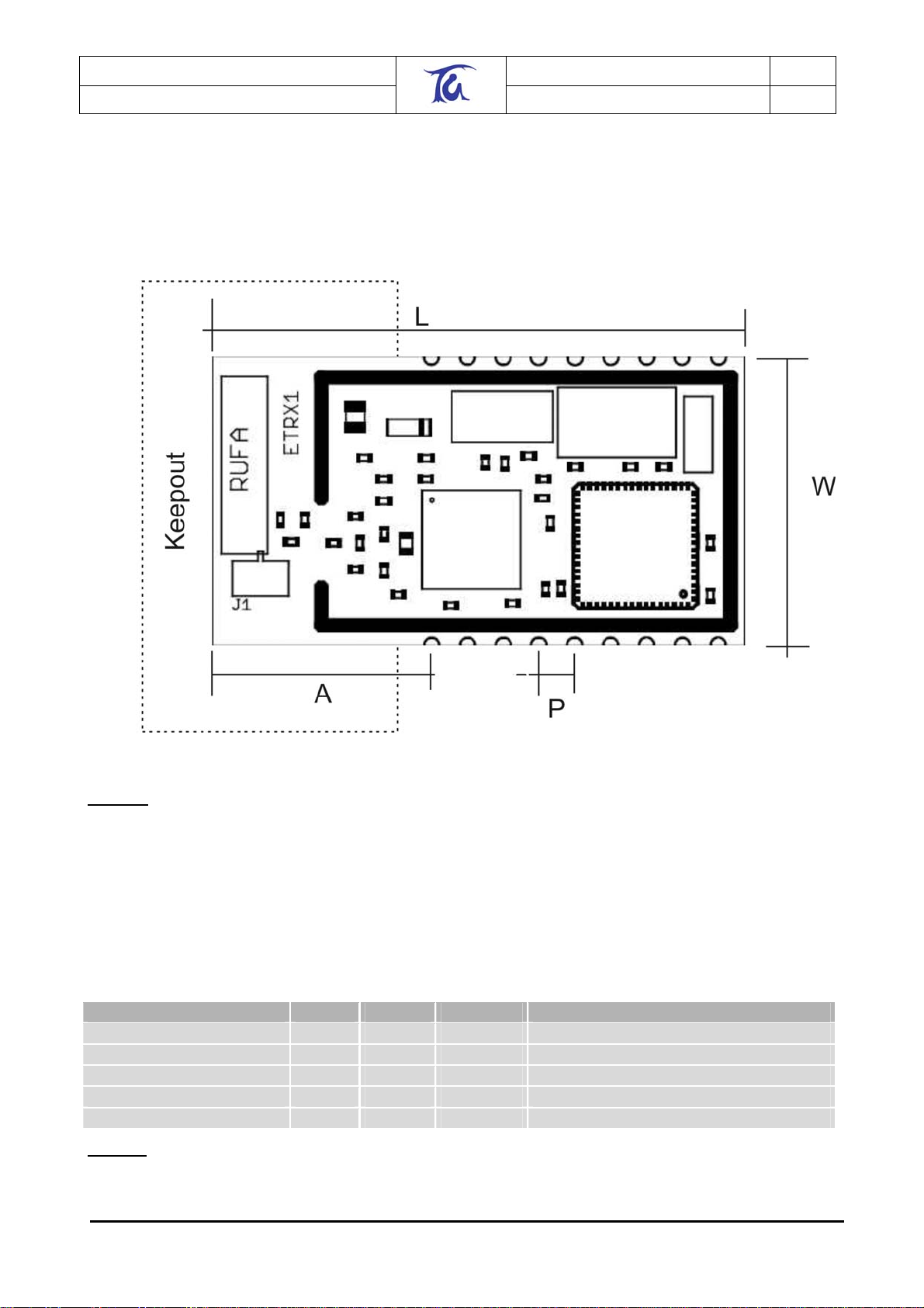
The physical dimensions are shown in table 9. Units are in mm.
Figure 4. Physical Dimensions of Module
For ideal RF-Performance when using the on-board antenna, the antenna should be located at the
edge of the carrier PCB. There should be no components, tracks or copper planes in the keep out
area which should be as large as possible, preferably 10-15mm around the antenna.
If using the U.FL RF-Connector the keep out area can be significantly reduced. The Module
transmit/receive range will depend strongly on the antenna used and also the housing of the
finished product.
Label Min. Typ. Max. Description
L 37.75 Length of the module
W 20.45 Width of the module
P 2.54 Pitch
A 15.5 Distance corner/centre 1st pad
H 3.4 3.6 Height of the Module
Table 9: Dimensions of module in mm
©2005 Telegesis (UK) Ltd ETRX1 Product Manual (Rev 1.06)
Page 42
Telegesis (UK) Limited
TG-ETRX1-PM-01-106 42
ETRX1
Preliminary Product Manual 1.06
13. Recommended Footprint
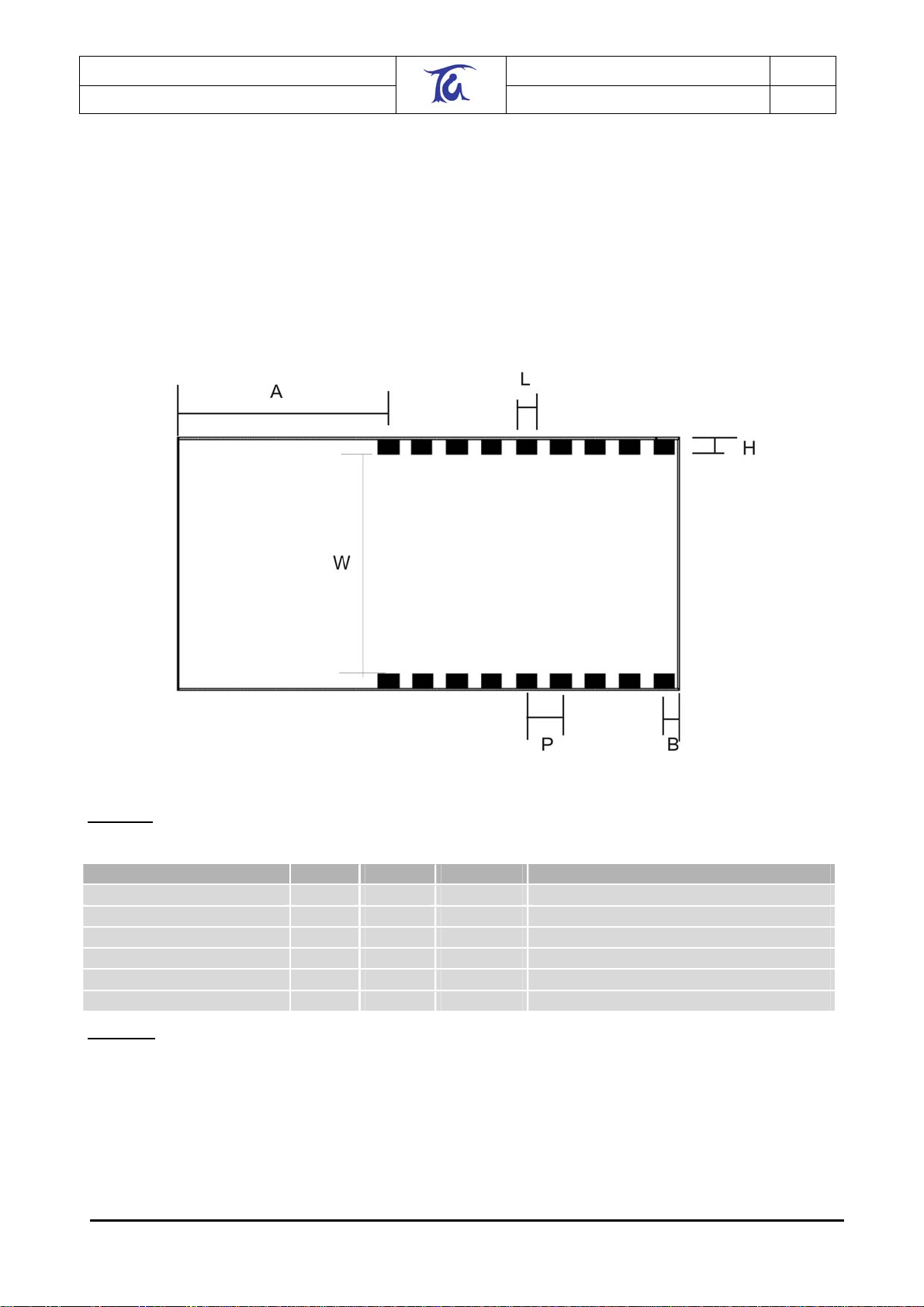
In order to surface mount the module, it is recommended to use pads which are 1.5mm wide and
1.2mm high as shown in table 10.
Care must be taken to ensure that on the surface underneath the module there are no exposed
pads or vias which might contact with the pads for the optional connector or any vias of the module
itself.
Figure 5. Recommended Footprint
Label Min. Typ. Max. Description
L 1.5 Length of a Pad
H 1.5 Width of a Pad
P 2.54 Pitch
B 1.9 Distance right corner/ centre pad 9
A 15.5 Distance left corner/centre pad 1
W 18.5 Distance between pad inside edges
Table 10: Dimensions of Footprint in mm
©2005 Telegesis (UK) Ltd ETRX1 Product Manual (Rev 1.06)
Page 43

Telegesis (UK) Limited
TG-ETRX1-PM-01-106 43
ETRX1
Preliminary Product Manual 1.06
14. Ordering Information
Ordering/Product Code Description
ETRX1 *
ETRX1HR *
ETRX1DVK *
Notes:
• Customers’ PO’s must state the Ordering/Product Code.
• There is no “blank” version of the ETRX1 Module available. All Modules carry both the
EmberNet Stack and the Telegesis AT style Command Layer. (Where customers wish to
add their own firmware they can erase and write it to the flash memory of the Atmel).
• Please contact Telegesis if you require additional AT style commands or specific
integration assistance.
Table 11. Ordering Information
Ember ZigBee Ready Module with:
• AT Style Command Interpreter
• Integrated 2.4Ghz Antenna
• No Harwin Connector included
Ember ZigBee Ready Module with:
• AT Style Command Interpreter
• Hirose U.FL Antenna Connector
• No Harwin Connector included
Ember ETRX1 Development Kit with:
• 1 x ETRX1 Module
• 1 x ETRX1HW Module (with Harwin Connector fitted)
• 1 x ETRX1DV Development Board
• 1 x PSU
• 1 x RS232 Cable
©2005 Telegesis (UK) Ltd ETRX1 Product Manual (Rev 1.06)
Page 44

Telegesis (UK) Limited
TG-ETRX1-PM-01-106 44
ETRX1
Preliminary Product Manual 1.06
15. Trademarks
All trademarks, registered trademarks and products names are the sole property of their respective
owners.
16. Disclaimer
Product and Company names and logos referenced may either be trademarks or registered
trademarks of their respective companies. We reserve the right to make modifications and/or
improvements without prior notification. All information is correct at time of issue. Telegesis (UK)
Ltd does not convey any license under its patent rights or assume any responsibility for the use of
the described product
17. Contact Information
Website:
E-mail [email protected]
Telegesis (UK) Limited
Marlow Business Centre
84 Station Road
Marlow
Bucks. SL7 1NX
UK
Tel: 01628 894347
Fax: 01628 894333
www.telegesis.com
18. References
Telegesis -
Ember -
Atmel -
Gigaant -
©2005 Telegesis (UK) Ltd ETRX1 Product Manual (Rev 1.06)
www.telegesis.com/etrx1
www.ember.com
www.atmel.com
www.gigaant.com
 Loading...