

Telegesis TG-ETRXn-UG-01-104 User Manual
Telegesis (UK) Limited
TG-ETRXn-UG-01-104
1
User Guide
1.04
ETRX1 and ETRX2
Telegesis
©2008 Telegesis (UK) Ltd ETRXn User Guide (Rev 1.04)
TG-ETRXn-UG-01-104
ETRXn WIRELESS MESH NETWORKING MODULES
Firmware R2xx User Guide

Telegesis (UK) Limited
TG-ETRXn-UG-01-103
2
User Guide
1.04
ETRX1 and ETRX2
©2008 Telegesis (UK) Ltd ETRXn User Guide (Rev 1.04)
Table of Contents
1 INTRODUCTION..................................................................................................... 3
2 GETTING STARTED .............................................................................................. 3
3 NETWORK MANAGEMENT ................................................................................... 9
3.1 Overview ................................................................................................................. 9
3.2 Device Types ........................................................................................................ 10
3.3 Network Establishment and Maintenance ............................................................. 11
3.3.1 AT+EN – Establish Network .................................................................................. 11
3.3.2 AT+DASSL – Disassociate Local Node ................................................................. 12
3.3.3 AT+DASSR – Disassociate remote device from PAN ............................................ 12
3.3.4 AT+JN – Join Network .......................................................................................... 12
3.3.5 AT+PANSCAN – Scan for all available channels .................................................. 12
3.3.6 AT+JPAN:cc,pppp - Join specific PAN .................................................................. 12
3.3.7 AT+N – Display network parameters ..................................................................... 12
3.3.8 AT+ESCAN – Scan the energy of all channels ...................................................... 12
3.3.9 AT+SN – Scan network for other nodes ................................................................ 12
3.3.10 AT+REMSN – Scan for remote device‟s direct neighbours.................................... 13
3.3.11 AT+LINKCHECK - Check link parameters with a neighbour .................................. 13
3.3.12 AT+PING - Indicate presence in the network ........................................................ 13
3.3.13 ATS & ATSREM – Read and write S-registers ...................................................... 13
3.4 Managing a Network ............................................................................................. 13
3.5 Maintaining a Network ........................................................................................... 13
4 DATA TRANSMISSION ........................................................................................ 14
4.1 Overview ............................................................................................................... 14
4.2 Broadcasts ............................................................................................................ 14
4.3 Raw data ............................................................................................................... 15
4.4 Unicasts ................................ ................................................................ ................ 15
4.5 S-Casts ................................................................................................ ................. 15
4.6 Channels ............................................................................................................... 16
5 S-REGISTERS ...................................................................................................... 17
5.1 Overview ............................................................................................................... 17
5.2 Radio Setup (S00-S03) ................................................................ ......................... 17
5.3 Module Setup (S04-S0A) ...................................................................................... 18
5.4 I/O-related registers (S0B-S14) ............................................................................. 19
5.5 Event Management (S15-S28) .............................................................................. 21
5.5.1 Interrupts ............................................................................................................... 21
5.5.2 Timers ................................................................................................................... 22
5.5.3 Power Management (S29-S2A) ............................................................................. 22
5.5.4 Functionality text (S2B-S2C) ................................................................................. 23
5.6 Device-specific registers (S2D-S35) ...................................................................... 23
6 SPECIALISED I/O ................................................................................................ 24
6.1 Tone Generation at Pin I/O3 ................................................................................. 24
6.1.1 ETRX1 Settings .................................................................................................... 24
6.1.2 ETRX2 Settings .................................................................................................... 25
7 REVIVING AN UNRESPONSIVE MODULE ......................................................... 26
8 SECURITY ............................................................................................................ 26

Telegesis (UK) Limited
TG-ETRXn-UG-01-103
3
User Guide
1.04
ETRX1 and ETRX2
©2008 Telegesis (UK) Ltd ETRXn User Guide (Rev 1.04)
9 NETWORK COMMISSIONING ............................................................................. 27
10 APPLICATION EXAMPLES ................................................................................. 28
10.1 Simple Temperature Sensor ................................................................................. 28
10.2 Switch Application ................................................................................................. 28
10.3 Serial Port Replacement ................................................................ ....................... 29
10.4 Using a Host Microcontroller ................................................................................. 29
10.5 Custom Functionality ............................................................................................. 29
10.6 Developing Your Own Firmware ............................................................................ 29
11 BUILT-IN FUNCTIONALITY ................................................................................. 30
12 GLOSSARY .......................................................................................................... 34
13 MODULE PINOUTS .............................................................................................. 34
14 TRADEMARKS .................................................................................................... 36
15 DISCLAIMER ........................................................................................................ 36
16 CONTACT INFORMATION .................................................................................. 36
17 REFERENCES ..................................................................................................... 37
1 Introduction
This document gives an introduction on how to set up and operate the Telegesis ETRXn ZigBee®
modules with firmware revisions R2xx. The examples in this document assume that you are using
the ETRXnDVKx Development Kit. However most of the features described can also be evaluated
using any custom hardware based on the ETRX1 or ETRX2 modules.
Towards the end of this document a number of possible application scenarios are listed in order to
show the versatility of the ETRXn modules.
Some of the details will vary from one firmware version to another; this guide was written when
R212 was current.
Do not use this guide if you are using R1xx firmware as the AT Command set is different. Please
check the Telegesis website www.telegesis.com regularly for updates.
2 Getting Started
The ETRXn sends and receives commands and data from its host computer through a UART as
ASCII strings. You can use your own application software, a tool such as HyperTerminal, or our
own Telegesis Terminal which is a free download from our website. To use it, first install .NET
Framework Version 1.1 Redistributable Package from Microsoft. This is currently available at
www.microsoft.com/downloads/details.aspx?familyid=262D25E3-F589-4842-8157034D1E7CF3A3&displaylang=en
Note that Version 2 or later is not sufficient as it supplements Version 1.1 but does not replace it.
Then download Telegesis Terminal from our website at www.telegesis.com/ZigBee/Dsoftware.htm.
Telegesis (UK) Limited
TG-ETRXn-UG-01-103
4
User Guide
1.04
ETRX1 and ETRX2
©2008 Telegesis (UK) Ltd ETRXn User Guide (Rev 1.04)
Note: Telegesis Terminal is not a GUI that interprets the AT commands and sends instructions to
the ETRX2 in another format. It does not alter the AT commands in any way – the ETRX2
receives them exactly as described here and in the AT Command Manual. Likewise, if you are
writing your own terminal application, it should send and receive data as formatted in our manuals.
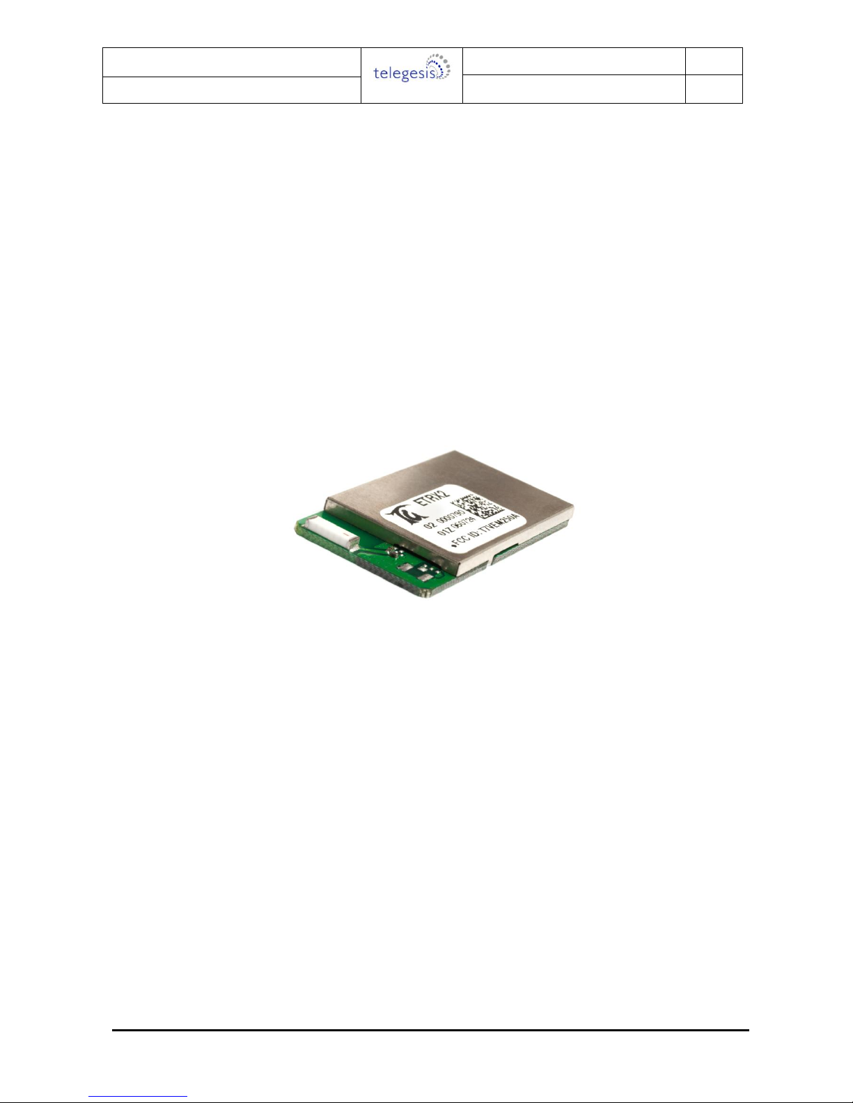
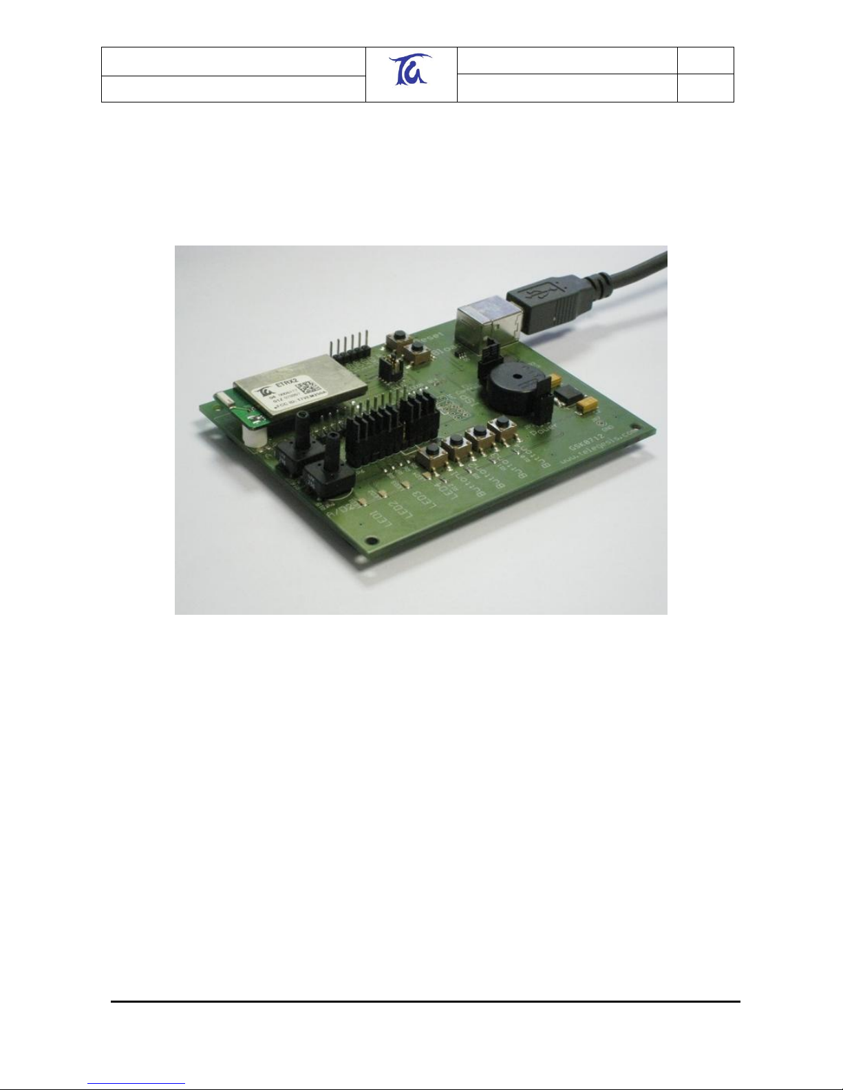
In order to get started, plug an ETRXn module on to each development board which forms part of
your set-up and connect at least one development board to a PC using the serial or USB cable
provided.
Figure 1. Development board with module mounted
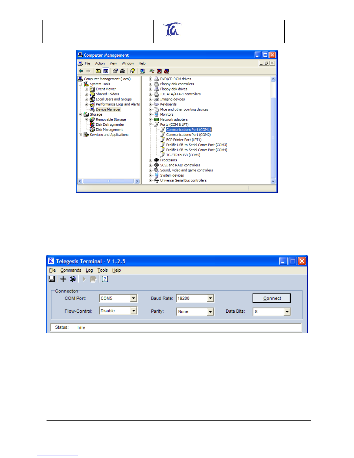
Power up all of the development kits and module carrier boards (MCBs) and start the Telegesis
Terminal application on the PC. You need to know which of your computer‟s COM ports is
connected to the development board, which may not be obvious if you are using a USB-to-serial
adaptor, for example. To check, open your PC‟s Device Manager; there are several ways in
Windows XP, but the simplest is to right-click on “My Computer” and select “Manage”, then
“Device Manager”. In this example there are two USB-to-serial adaptors in COM3 and COM4 and
a USB stick in COM5:
Telegesis (UK) Limited
TG-ETRXn-UG-01-103
5
User Guide
1.04
ETRX1 and ETRX2
©2008 Telegesis (UK) Ltd ETRXn User Guide (Rev 1.04)
Figure 2. Windows Device Manager
The connection should be set up using the default values as shown in Figure 3. By default the
module uses a bit-rate of 19200bps, no parity, 8 data bits, 1 stop bit and no flow control. Optionally
XON/XOFF as well as hardware flow control is supported. (See section 10 for more detail).
Pressing the “Connect” button establishes the connection to the ETRXn module on the
development board.
Figure 3. Setup of the Serial Connection
The module will accept commands starting with the “AT” prefix after it has booted up successfully.
Booting up can take 1-2 seconds and on completion the module will prompt “OK”.
Entering the “ATI” command into the terminal window, followed by <Enter>, will cause the module
to display its manufacturing information. Alternatively the “Info” button in the “Module Control”
section can be pressed, causing the “ATI” command to be sent to the local module. After executing
a command the module will prompt “OK” or an error code as explained in the AT command
dictionary.
Telegesis (UK) Limited
TG-ETRXn-UG-01-103
6
User Guide
1.04
ETRX1 and ETRX2
©2008 Telegesis (UK) Ltd ETRXn User Guide (Rev 1.04)
In order to communicate with other modules a module must be part of a PAN (Personal Area
Network). To find out about the status of the local module simply issue the “AT+N” command and
this will show you the module‟s network status. If the module is not part of a PAN (response
“+N:none”) it can be instructed to join an existing PAN using the “AT+JN” command, or to start a
new PAN for other units to participate in using the “AT+EN” command. In order to exchange
messages all units need to be on the same PAN, i.e. have the same channel and the same PAN
ID. The response “+N:cc,pppp” displays the channel number (cc) and the PAN ID (pppp) of the
current PAN. If you have a module which is part of a separate PAN simply use the “AT+DASSL”
command to leave the current PAN and try joining the correct PAN using the “AT+JN” command.
Network establishment and maintenance is described in more detail in Section 3.3.
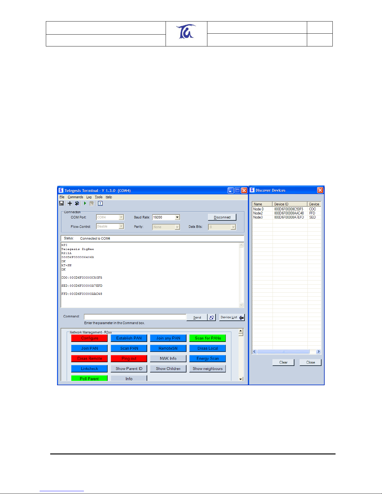
In order to find other nodes which are part of the same PAN press the “Scan Pan” button which
sends the “AT+SN” command to the local module. (Your terminal software may expect a
parameter after the command, namely the number of hops to interrogate. Just type a suitable two-
digit number e.g. “08”). The module will now transmit a request to all the modules within eight
hops asking them to identify themselves. When modules are found the “Discover Devices” window
will pop up (if not already open) and display a list of all of the modules which have reported in. See
Figure 4.
Figure 4. Results of a network search
In this example three additional modules were detected: one ZigBee Coordinator (COO), one
ZigBee Router (FFD) and one Sleepy End Device (SED). For an explanation of the device types
see Section 3.2.
Telegesis (UK) Limited
TG-ETRXn-UG-01-103
7
User Guide
1.04
ETRX1 and ETRX2
©2008 Telegesis (UK) Ltd ETRXn User Guide (Rev 1.04)
An alternative way to search the PAN for other modules is to hit the “Configure” button. As well as
scanning the PAN as before, it adds extra buttons to control the buzzer and LEDs on each remote
module.
Depending on the previous usage of your development kit, units may either immediately
communicate with each other on the same PAN, or they may be off-line. If the unit connected to
your PC does not report that it has joined a PAN within a few seconds of power-up, a suitable
procedure would be:
1. issue the command AT+JN to join any existing PAN or
2. issue the command AT+PANSCAN followed by AT+JPAN:<channel>,<PAN ID> to find and
join a specific PAN or
3. Wait for the module to automatically join a PAN as described in section 3.1.
4. If the steps above do not reveal an existing PAN, issue the command AT+EN to initiate a
new PAN. Others units searching for a PAN will then attach to it within a few minutes, and
be reported with a “NEWNODE:<EUI64>” prompt.
A common problem occurs when the user establishes a PAN and waits for the other devices to join
it … and waits … and waits. This usually means the the other devices are already in a PAN of
their own (set up when they were last used), and as long as they can communicate amongst
themselves they will ignore the new network. If you disassociate the local node and use the
AT+PANSCAN or AT+JN command, this will reveal the pre-existing PAN; you can join it and then
either carry on using it or disassociate the remote nodes and start afresh.
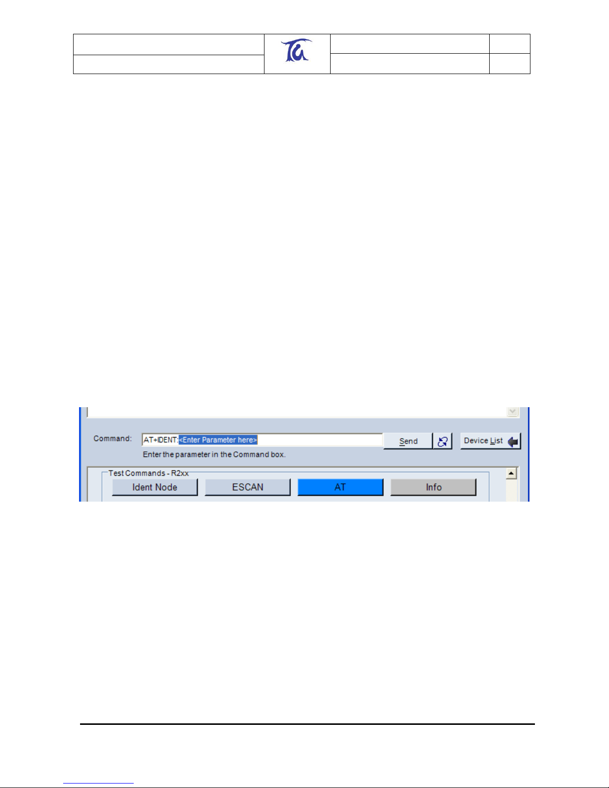
In order to find out which of the detected modules is which, press the “Ident Node” button in the
“Test Commands” section of the buttons. This command requires an additional parameter,
therefore instead of sending a command straight to the local node the command is displayed in the
command bar with the text “<Enter Parameter here>” highlighted.
Figure 5. Entering parameters
Now, double click on any entry in the “Discover Devices” window and the serial number of the
selected device will be added as a parameter. The command is executed by either pressing
“Enter”, or by clicking the “Send” button.
When executing this command the local module will send a request to the module with the
specified serial number asking it to identify itself. A module can identify itself by playing a tune on
a buzzer which is connected to I/O3. If you are using the devkit and you do not hear a tune check
that the jumper for I/O3 is set so that I/O3 is an output (factory default); on the MCBs the buzzer is
directly connected to I/O3.
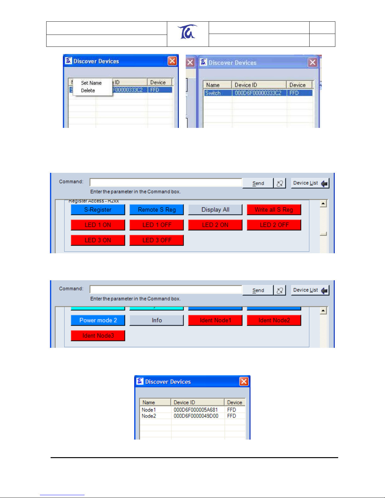
Having identified which module is which you can now give each module a name using the
Telegesis Terminal software. To do this, right click on the entry in the “Discover Devices” window
(as shown in Figure 6) and enter the name when prompted to do so. Please note that this name is
not written to the module itself, it only represents a temporary name which can be used to simplify
the evaluation process using the Telegesis Terminal software.
Telegesis (UK) Limited
TG-ETRXn-UG-01-103
8
User Guide
1.04
ETRX1 and ETRX2
©2008 Telegesis (UK) Ltd ETRXn User Guide (Rev 1.04)
Figure 6: Device Naming
If you have used the “Configure” button, your button window will resemble Figure 7 and Figure 8
and the device table Figure 9.
Figure 7. "LED" buttons after a “Configure” operation
Figure 8. "IDENT" buttons after a “Configure” operation
Figure 9. Device table after a “Configure” operation
Telegesis (UK) Limited
TG-ETRXn-UG-01-103
9
User Guide
1.04
ETRX1 and ETRX2
©2008 Telegesis (UK) Ltd ETRXn User Guide (Rev 1.04)
After identifying all of the devices in the network we can also send messages to any devices within
range. In order to send a broadcast message to all of the devices, use the “AT+BCAST:”
command followed by the number of hops you want the broadcast to travel followed by the text you
wish to broadcast, or simply press the “Broadcast Button” and enter parameters into the Command
line. (E.g. “AT+BCAST:01,Hello World”)
In order for the remote nodes to display received data they will need to be connected to a PC‟s
serial port.
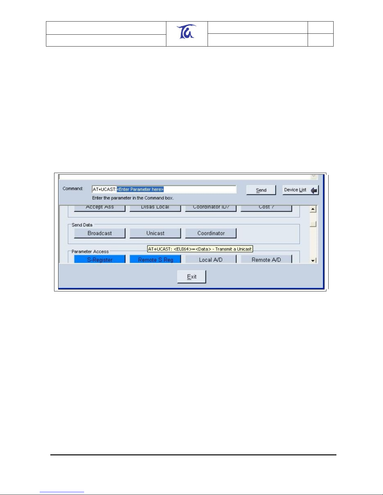
It is also possible to send data to an individual node using a Unicast. To send a Unicast press the
“Unicast” button and then double click on the entry of the recipient in the “Discover Devices”
window and enter the data you wish to transmit preceded by an equal sign. If you do not know the
syntax of a command, hold the mouse pointer over the respective button and the tool tip text will
display the format of the command as shown in Figure 10.
Figure 10. Tool tip texts
So far we have set up all of the hardware required for a meshing network, identified and named the
individual modules using the Telegesis Terminal Software and actioned a few simple commands in
order to learn the functionality of the AT-Style command line interface.
This level of complexity may well be all you need for your application. Before we now look at
additional commands we need to introduce some more theoretical information about wireless mesh
networks.
3 Network Management
3.1 Overview
A ZigBee® (-like) network is formed from the inside out. This means that a device which is
instructed to start a network becomes a so-called coordinator and scans all available radio
channels, picks the one with the least traffic and generates a random PAN ID in order to start a
network; other nodes can then join in.

Telegesis (UK) Limited
TG-ETRXn-UG-01-103
10
User Guide
1.04
ETRX1 and ETRX2
©2008 Telegesis (UK) Ltd ETRXn User Guide (Rev 1.04)
Another scenario is that a node scans for an available network to join, and if no network is found
the node can choose to become a coordinator and start its own network as described above.
Remote nodes are then capable of finding this newly established network and joining it. As more
and more remote nodes join, the network grows from the inside out. If the network is spread over
a wide area, a new node may be out of range of the coordinator and will join the PAN via another
node, which will act as a router. Messages may then pass across the network in more than one
“hop”.
The Telegesis AT command driven software supports point-to-point messages travelling up to six
hops and broadcast messages travelling up to ten hops through the network.
In the examples of Section 3.3, the commands used to establish and maintain a network are
described. For a list of all available commands please refer to the AT-Command dictionary
document.
3.2 Device Types
A ZigBee® network can consist of three different device types:
ZigBee Coordinator (ZC)
ZigBee Router (ZR)
ZigBee End Device (ZED)
ZigBee Coordinators, Routers and End Devices were formerly known as Coordinators, Full
Function Devices and Reduced Function Devices. ZigBee End Devices can be further classified
as Sleepy End Devices (SED) and Mobile End Devices (MED).
A ZigBee Router can route messages between ZigBee® devices, whereas a ZigBee End Device
does not provide any routing capabilities. The primary difference between the two is that a ZR
needs to constantly be awake in order to fulfil its routing responsibilities, whereas a ZED can spend
its life in sleep mode as it has no routing responsibilities.
ZRs consequently consume more power than ZEDs, therefore you must evaluate which type of
device will suit your application best. See Section 10 for a list of example scenarios.
A Coordinator is effectively a Router which has started the network. Each network must have only
one coordinator node. With the meshing stack of EmberZNet a mesh will continue to function even
if the coordinator leaves the PAN.
A ZigBee End Device has no routing responsibilities and joins the network via a ZigBee Router (its
“parent”). The parent will buffer up incoming messages for its “child” while it is asleep. The child
should poll regularly to check if there are any new messages pending on the parent device to
prevent loss of messages due to buffer overflow. The parent will also act as a relay point for its
childrens' outgoing messages. For example when a child wants to send a broadcast it sends the
data to its parent and the parent in turn will initiate the broadcast.
There are two different types of ZigBee End Devices defined in EmberZNet:
sleepy end device
mobile end device
The sleepy end device will remain in its parent‟s child list permanently (or until the parent is reset
or leaves the network by itself). This implies that the sleepy end device should not physically move
away from its parent and join a new parent, as it will still block a child entry at its previous parent.
A mobile sleepy end device will time out and be erased from the parent‟s child table if it does not
poll its parent within 3 seconds. When a mobile end device cannot find its parent it assumes that it
has moved and will search for a new parent. A device need not be defined as “mobile” merely if it

Telegesis (UK) Limited
TG-ETRXn-UG-01-103
11
User Guide
1.04
ETRX1 and ETRX2
©2008 Telegesis (UK) Ltd ETRXn User Guide (Rev 1.04)
changes its physical location; the key point is it that moves enough within the area covered by a
PAN to need a new parent. If, for example, the PAN only contains one parent and a number of
end devices (a “star” topology), there is no point in defining the ZEDs as mobile since there is no
other parent to adopt them.
In the Telegesis AT command software each routing device can have up to eight sleepy end
devices and up to eight mobile end devices.
A module becomes a coordinator by issuing AT+EN as described above. Whether a device joins
as a ZigBee Router or sleepy/mobile end device is determined by the settings in S06 at the instant
the device joins a PAN, so if you are currently joined as a router and want to become a mobile end
device you have to complete the following steps:
1. Leave the network
2. Change S06 accordingly
3. Re-join the network
An end device will always keep its radio switched off (unless used) and therefore consume less
power than a router, even when fully awake.
In power levels 0 to 2 (see section 5) by default an end device will poll its parent for new data once
every second via the built-in functionality. This timing can be altered or disabled altogether if
required. Polling takes less than 10ms, so the battery life of end devices can be maximised. Up to
three incoming broadcasts are stored on each parent until overwritten by new broadcasts.
Unicasts can only be stored for as long as the timeout period on the sending device, so when
expecting to receive unicasts you are required to poll at least in the default interval of once every
second.
When sending a unicast from an end device the unit will keep polling for the acknowledgement
until it has been received or the transmission has timed out regardless of the configured polling
interval.
3.3 Network Establishment and Maintenance
3.3.1 AT+EN – Establish Network
When the local module is not a member of a network, it can initiate a new one and become that
network‟s coordinator. Issuing the “AT+EN” command scans all the available channels, looking for
the one with the lowest energy level; it then generates a random PAN ID, checks to ensure that a
network with this PAN ID does not already exist and then starts a PAN. A unit on which this
command has been executed automatically becomes the network‟s coordinator and remains the
coordinator until it leaves the network using “AT+DASSL”. Neighbouring nodes can now join this
newly established network using “AT+JN”.
[If you are familiar with EmberNet R1** meshing technology and preferred the old way of picking
the channel and PAN ID manually, there is no need to worry as this is still possible. S-Register 00
holds a 16-bit word in which each bit represents one of the available 802.15.4 channels 11-26.
Setting a bit to 1 enables a channel, and setting a bit to 0 disables it. It is therefore possible to
mask out channels which are known to be noisy in the chosen application environment. Setting
the mask to fifteen 0s and a single 1 will force operation on one radio channel. (The mask can also
be used to block ETRXn transmission on channels that you wish to reserve for other systems that
may not yet be in operation.)]
Register S01 allows you to select a preferred PAN ID. By default this register is set to FFFF, which
causes the coordinator to pick a random PAN ID when establishing a PAN. Any number between
0000 and 3FFF will cause the unit to start a PAN with the specified PAN ID unless that particular

Telegesis (UK) Limited
TG-ETRXn-UG-01-103
12
User Guide
1.04
ETRX1 and ETRX2
©2008 Telegesis (UK) Ltd ETRXn User Guide (Rev 1.04)
PAN ID is used by another network. In this case, a randomly generated number is allocated
instead.
3.3.2 AT+DASSL – Disassociate Local Node
To check for the presence of PANs (AT+PANSCAN), measure the signal energy in the radio
channels (AT+ESCAN), or join a different network, a node must first disassociate itself from its
current network using the “AT+DASSL” command.
3.3.3 AT+DASSR – Disassociate remote device from PAN
To move a node from one PAN to another, it must first be disassociated. This may be necessary
when it is intended to swap a coordinator unit for another (which will initiate a new PAN).
3.3.4 AT+JN – Join Network
The node will scan all channels for a PAN which allows units to join. Once it has found such a
network the node will join in. This is a very convenient way of joining a network; it does not,
however, give the local node a choice of which network to join if there is more than one network
available.
3.3.5 AT+PANSCAN – Scan for all available channels
“AT+PANSCAN” will produce a list of all available channels from which you can manually choose
the one you wish the unit to join. To perform this you need to use the “AT+JPAN” command.
3.3.6 AT+JPAN:cc,pppp - Join specific PAN
cc is the channel number and pppp is the PAN ID of the PAN which is to be joined. There are also
a number of auxiliary commands, shown below.
3.3.7 AT+N – Display network parameters
“AT+N” reports the type of the local node (see section 3.3), the channel number and PAN ID, and
the transmitter power.
3.3.8 AT+ESCAN – Scan the energy of all channels
”AT+ESCAN” scans all channels which are not masked out in register S00 and displays their
energy levels.
3.3.9 AT+SN – Scan network for other nodes
This functionality has been extended so that it is now possible to specify the number of hops the
search should cover (1 to 6). This combines the AT+SN and AT+SNEIGHBOURS command of
R1xx into a single command. Optionally the RSSI and LQI readings between the remote device
and the local device can be displayed if bit 6 of register S06 is set as described in section 5.
 Loading...