

Page 1
Telegesis
TG-ETRXn-R309-AT-Commands
ETRX3 series
AT-Command Dictionary 3.09
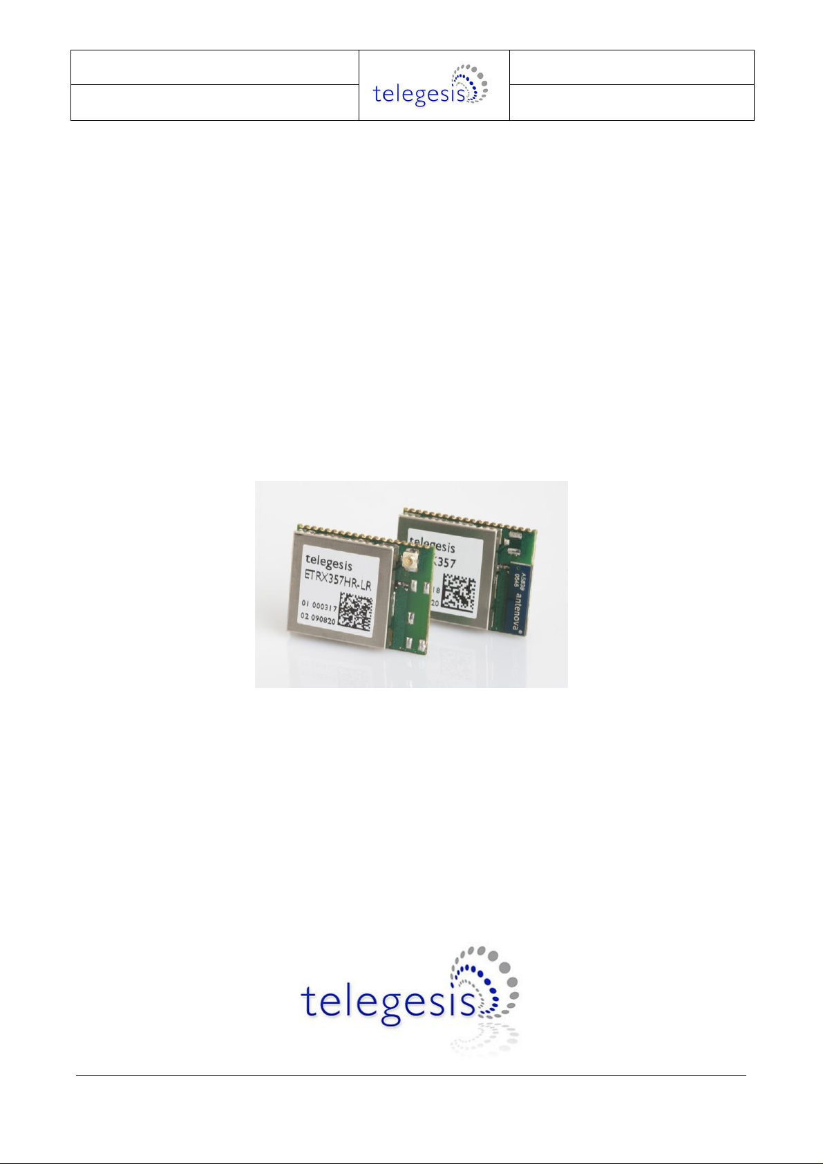
ETRX3 Series ZigBee Module
AT-Command Dictionary
Firmware R309
EmberZNet 5.4.0 stack
©2015 Telegesis (UK) Ltd AT Command Manual July 2015 (Rev 3.09)
Page 2

R309 AT Commands
Table of Contents
1 INTRODUCTION ................................................................................................................. 4
1.1 The first step .................................................................................................................... 4
1.2 Module overview .............................................................................................................. 4
1.3 Document Overview ......................................................................................................... 4
1.4 Network topology ............................................................................................................. 5
1.5 The ADCs ........................................................................................................................ 5
1.6 RTC Related Commands ................................................................................................. 5
1.7 A Note on ZigBee® Compliance ....................................................................................... 5
1.8 Important notes ................................................................................................................ 6
1.8.1 Hardware compatibility ..................................................................................................... 6
1.8.2 Unexpected start-up in bootloader mode .......................................................................... 6
1.8.3 Compatibility with other devices ....................................................................................... 6
1.8.4 Persistence of network parameters .................................................................................. 6
2 AT STYLE COMMAND CONVENTIONS ............................................................................ 7
2.1 Parameters ...................................................................................................................... 8
2.2 Prompt Overview.............................................................................................................. 9
2.3 Device Overview ............................................................................................................ 11
2.3.1 ZigBee types .................................................................................................................. 11
2.3.2 Non-ZigBee types .......................................................................................................... 11
2.4 Addressing modes ......................................................................................................... 11
2.5 AT Command Overview ................................................................................................. 13
2.6 Module Control & Configuration Commands .................................................................. 15
2.7 Network Control & Configuration Commands ................................................................. 21
2.8 Messaging...................................................................................................................... 40
2.9 Binding Management (ETRX3 Series only) .................................................................... 58
2.10 Time-related commands ................................................................................................. 63
3 LIST OF ERROR CODES ................................................................................................. 65
4 S-REGISTERS .................................................................................................................. 67
4.1 Recovery of the Factory Default Settings ....................................................................... 69
4.2 S-Registers for Network Setup ....................................................................................... 70
4.3 S-Registers for Module Setup ........................................................................................ 75
4.4 I/O related S-Registers ................................................................................................... 81
4.5 S-Registers Defining the Functionality of the Module ..................................................... 90
4.6 Advanced Settings ....................................................................................................... 104
5 BUILD IN FUNCTIONALITY ........................................................................................... 112
6 ETRX357 POWER CONSUMPTION (PROVISIONAL DATA) ........................................ 115
7 NOTES ON ENERGY LEVELS AND LQI ....................................................................... 116
7.1 Interpreting LQI ............................................................................................................ 116
7.2 Interpreting RSSI Energy Levels .................................................................................. 117
8 TRADEMARKS ............................................................................................................... 118
9 DISCLAIMER .................................................................................................................. 118
10 CONTACT INFORMATION ............................................................................................. 118
©2015 Telegesis (UK) Ltd - 2 - AT Command Manual (Rev 3.09)
Page 3

R309 AT Commands
11 REFERENCES ................................................................................................................ 118
12 APPENDIX A. FORMING A SECURE NETWORK ........................................................ 119
13 APPENDIX B. BOOTLOADING NEW FIRMWARE ....................................................... 120
13.1 Bootloading through the serial port ............................................................................... 120
13.2 Bootloading over the air ............................................................................................... 121
©2015 Telegesis (UK) Ltd - 3 - AT Command Manual (Rev 3.09)
Page 4

R309 AT Commands
1 Introduction
1.1 The first step Send the command “ATI” to a module to find its firmware version. If it is not R309 then you should
refer to the correct version of the AT command manual, or send an e-mail to
[email protected] requesting a copy of the R309 firmware file. All four variants of the
ETRX357 module share the same file.
Alternatively if your module has R309 and you prefer a different version, this can be provided on
request.
All the standard AT command set firmware files are free of charge to users who already have the
ETRXn devices, but they must only be used on Telegesis modules.
1.2 Module overview
This document describes the AT-Command interface firmware of the ETRX3 series ZigBee PRO
wireless meshing modules. It applies to the R309 firmware, which can be loaded on to all products
of the ETRX3 module series, for example:
- ETRX357, ETRX357-LR, ETRX357-LRS
- ETRX357HR, ETRX357HR-LR, ETRX357HR-LRS
- ETRX3585, ETRX3587 and ETRX3588
- ETRX3USB
- ZigBee Communications Gateway
The Telegesis ZigBee modules have been designed to be built into any device and provide a low
cost, low power ZigBee solution based on the industry leading EmberZNet ZigBee stack.
Integration into a wide range of applications is made easy using a simple AT-style software
interface and advanced hardware design.
No RF experience or expertise is required to add this powerful wireless networking capability to
your products. Telegesis ZigBee modules offer fast integration opportunities and the shortest
possible time to market for your product.
Important note
Using the AT-Command interface described in this document can shorten the time to market
significantly, however customers using the range of Telegesis modules also have the option of
using Ember’s EZSP interface firmware or of developing custom firmware using the Ember
Development tools.
1.3 Document Overview
This document is meant as an AT-Command and S-Register reference for R3xx revisions of the
firmware based on EmberZNet3.x and EmberZNet4.x. In order to learn how your products can
benefit from wireless mesh networking please also refer to the following documents:
ETRX3 Product Manuals
©2015 Telegesis (UK) Ltd - 4 - AT Command Manual (Rev 3.09)
Page 5

R309 AT Commands
R3xx Firmware User Guide
Migration guide for existing R2xx firmware customers
ETRX3 Development Kit User Guides
Application notes from www.telegesis.com
The ETRX3 Product Manuals concentrate on the hardware specification of the modules. The
Development Kit Product Manuals contain all of the information required to set up your
development kit and run firmware upgrades where necessary.
1.4 Network topology
A network consists of a ZigBee Coordinator (ZC) which started the network, ZigBee Routers (ZR)
and ZigBee End Devices (ZED). There do not have to be any routers (other than the coordinator,
which functions as a router) or end devices in any given network. Each router can support up to
30 end devices in any combination of non-sleepy, sleepy and mobile End Devices. The network is
always formed as a mesh according to the ZigBee PRO featureset of the ZigBee standard; the tree
structure is not available.
By default the module joins a PAN as a router, but modifying register S0A allows you to define it as
an end device. The coordinator is simply the device that first establishes the PAN, and it should
not be allowed to leave the PAN as it is not possible for a node that is already joined to the PAN to
take over the role of a coordinator or Trust Centre.
1.5 The ADCs
The ETRX357 can operate up to 4 ADCs, which are individually enabled by settng the appropriate
bits in register S15. A reading is taken each time one of the registers S1F-22 is read, or when a
built-in function is executed which reads an ADC. If bit 8 of S15 is set the 1.2V Vref level is
presented at pin PB0 for the brief interval while the reading is taken.
Mode: single-ended
Range: 0-1200mV
Resolution: 14 bits
Units: 1 LSB = 0.1mV
Max load on PB0: 1mA
1.6 RTC Related Commands
The module runs a real time clock which can be set, read and synchronized against a time server
with the commands shown in this chapter. Please note that the basis of the real time clock is an
on-chip RC timer which gets calibrated against the external quartz crystal. Overall the accuracy is
not high and will vary with temperature, so if an accurate RTC is to be maintained frequent resynchronization with a time server is required.
1.7 A Note on ZigBee® Compliance
The Telegesis R300 firmware has been tested and certified for MSP (manufacturer specific profile)
compliance by a test house appointed by the ZigBee Alliance.
©2015 Telegesis (UK) Ltd - 5 - AT Command Manual (Rev 3.09)
Page 6

R309 AT Commands
This certification includes tests guaranteeing that:
- Modules running the Telegesis AT-Command set will not interfere with existing ZigBee
Networks in a malicious way
- Modules running the Telegesis AT-Command set can join a 3rd party ZigBee PRO network
and use its routing capabilities
- Modules running the Telegesis AT-Command set can allow 3rd party nodes to join into a
network consisting of Telegesis nodes and use its routing capabilities
In addition to implementing a manufacturer specific application profile the AT-Command set allows
for transparency allowing communication with 3rd party nodes running any public application
profile. In addition to this a transparent endpoint has been added allowing a host processor to
implement any public application profile in fully transparent mode.
If you want to use the term ZigBee or the ZigBee Logo in your product documentation the current
regulations state that you have to
(i) Be at least an adopting member of the ZigBee Alliance in the year you release your product
(ii) Implement a public application profile
If you intend to get your product certified feel free to contact Telegesis for additional information.
Also if you intend to build a product compliant to a public application profile (e.g. Home
Automation, Smart Energy) feel free to contact us to discuss your options.
1.8 Important notes
1.8.1 Hardware compatibility
R2xx firmware will not run on the ETRX3 series of modules.
1.8.2 Unexpected start-up in bootloader mode
The bootloader in the ETRX357 can be triggered using the command AT+BLOAD as described in
section 2, but it can also be triggered in hardware. If the PA5 pin is pulled low during the boot-up
of the module, the module will also enter the bootloader, so exercise caution when doing hardware
design and ensure that this pin is not grounded during start-up and reset. If unused the pad can
be left floating and a pull-up is not required.
1.8.3 Compatibility with other devices
Most features of the R3xx Telegesis AT-Command line Interpreter are part of a Manufacturer
Specific Profile using the ZigBee PRO feature set of ZigBee 2007. Interoperability with other
devices that use the ZigBee PRO featureset is limited to a number of transparent commands.
R3xx is not compatible with earlier versions of ZigBee which do not implement the ZigBee PRO
featureset, including Telegesis R2xx firmware. Also, it is not compatible with the ZigBee Smart
Energy profile as it lacks the required security key.
1.8.4 Persistence of network parameters
Once a device has joined a network as a coordinator, router or end device, it will retain its network
parameters if it is powered off and on again. It will still be a member of its original PAN, assuming
that PAN still exists, though an end device may need to find a new parent and it may have missed
an update of the network key. Certain S-registers will have been reset to default values, though,
which may change an end device’s power mode for example.
©2015 Telegesis (UK) Ltd - 6 - AT Command Manual (Rev 3.09)
Page 7

R309 AT Commands
Read Command
ATXXX?
Commands ending with a ‘?’ return the currently set value of the
parameter or parameters
Write Command
ATXXX=<…>
This command sets user-definable parameters as indicated by
the ‘=’ sign.
Execute Command
ATXXX
This command executes routines of the module and returns
parameters
2 AT Style Command Conventions
To simplify the communication with the modules, an AT-style command set, similar to the industry
standard Hayes modem control language, is used.
Each command must be preceded by the "AT" or "at" prefix. To terminate a command enter
<CR>. Any data not following this pattern is either not accepted by the module or will cause an
error message in response. Every command must be terminated with a <CR>, they cannot be
concatenated.
Commands are followed by an optional response that includes <CR><LF><Response><CR><LF>
and/or a prompt <CR><LF><Prompt><CR><LF> where the prompt could also be an error
message.
Example:
ATS00?<CR>
<CR><LF>FFFF<CR><LF>
<CR><LF>OK<CR><LF>
It is recommended to wait for an “OK” or “ERROR:XX” prompt before issuing the next command.
Any data which is prompted to the user is delivered in the format <CR><LF><prompt><CR><LF>.
Unless disabled in S0E or S0F prompts may appear whenever the corresponding event occurs.
Example:
<CR><LF><BCAST:000D6F000005A666,04=test><CR><LF>
A prompt intersecting a command being entered will not affect the command itself.
Throughout this document, only the responses and prompts are presented, <CR><LF> are omitted
intentionally. Sequences of AT commands in a single line are not supported.
The ETRX357 features a 128-byte FIFO to buffer incoming characters from the host processor,
which is sufficient to hold even the longest possible command. The ETRX357 features a 256-byte
FIFO buffer for incoming radio messages, which allows rapid reception of multiple messages
without loss of characters. To prevent a buffer overflow XON/XOFF handshaking is used. Optional
hardware handshaking can be enabled as described in the register description of S12 in section 4.
Table 1: Types of AT commands
When bit 7 of S12 is set each individual reply or prompt is additionally started with the STX and
ended with the ETX character to aid the interpretation of the incoming strings on a host processor.
©2015 Telegesis (UK) Ltd - 7 - AT Command Manual (Rev 3.09)
Page 8

R309 AT Commands
XX
8-bit hexadecimal number. Valid characters are 0-9, a-f and A-F
XXXX
16-bit hexadecimal number. Valid characters are 0-9, a-f and A-F
n
Number from 0-9
s
Sign
b
Bit (0 or 1)
c
character
<PID>
16-bit hexadecimal PAN ID (0000 to FFFF)
<EPID>
64-bit hexadecimal extended PAN ID
<channel>
decimal channel (802.15.4 channel 11-26)
<password>
8 character password
<EUI64>
64-bit IEEE 802.15.4 address in hexadecimal
<ioread>
32-bit hexadecimal number representing the reading of S1A
<data>
Custom Data
<ClusterList>
A list of 16 bit cluster identifiers in hexadecimal representation
<FirmwareRevision>
The Firmware Revision Number
2.1 Parameters
Each parameter must be entered in the correct format for any of the AT commands to execute
correctly. Optional parameters are marked with square brackets […].
Table 2: Different formats of parameters
©2015 Telegesis (UK) Ltd - 8 - AT Command Manual (Rev 3.09)
Page 9

R309 AT Commands
Prompt Overview
OK
OK terminator
ERROR:XX
Error number XX occurred
ACK:XX
Acknowledgement for message XX was received
NACK:XX
Acknowledgement for message XX was not
received
POLLED:XX
Shown on an end device when it polls its parent
and S11 bit D is set. XX codes are:
00 - Success
31 - no data pending on host
66 - poll could not be executed
40 - no ack from parent
SR:XX,<EUI64>,<NWK addr>,…
Route Record Message received
BCAST:[<EUI64>,]XX=<data>
[,<RSSI>,<LQI>]
A Broadcast with XX characters has been
received
MCAST:[<EUI64>,]XX=<data>
[,<RSSI>,<LQI>]
A Multicast with XX characters has been received
UCAST:[<EUI64>,]XX=<data>
[,<RSSI>,<LQI>]
A Unicast with XX characters has been received
INTERPAN:<ProfileID>,<ClusterID>,
<Msgtype>,<Option>,[GroupID],<PanID>,
<SrcAddr>,<MsgLength>,<Msg>
The device has received an interpan message
<ProfileID> - 16 bit hex
<ClusterID> - 16 bit hex
<Msgtype> - 8 bit hex
0x00 – Unicast
0x08 – Broadcast
0x0C- Multicast
<Option> - 16 bit hex. If it is 0x0002 the
<SrcAddr> will be source long address, and
otherwise it is source network address
[GroupID] – 16 bit hex, shown if the message is
sent to a group
<PanID> - 16 bit hex, source PAN ID
<SrcAddr> - 16 bit hex source node ID or EUI
<MsgLength> - 8 bit hex, message length
<Msg> - received message in hex format
RAW:snn,<data>
A raw message has been received with strength
snn dBm
SDATA:[<EUI64>,],<ioread>,<ADC0>,
<ADC1>,<sequenceNo>,<Vcc>
A data message has been received at the sink.
ADC data is ADC0 & ADC1
2.2 Prompt Overview
The following prompts can show up during the operation of the ETRX357 modules. Most of the
prompts can be disabled using register S0E and S0F.
©2015 Telegesis (UK) Ltd - 9 - AT Command Manual (Rev 3.09)
Page 10

R309 AT Commands
Prompt Overview
FN130:[<EUI64>],<NWK addr>,<ioread>,
<sequence no>,<S46>,[<ADC0>],
[<ADC1>],[<ADC3>],[<ADC3>]
A data message has been received at the sink.
The number of ADC data fields depends on how
many ADCs are activated at the sender
FFD:<EUI64>,<NWK addr>
A router announcing itself
SED:<EUI64>,<NWK addr>
A sleepy end device announcing itself
MED:<EUI64>,<NWK addr>
A mobile sleepy end device announcing itself
ZED:<EUI64>,<NWK addr>
An end device announcing itself
NEWNODE: <NWK addr>,<EUI64>,
<Parent NWK addr>
Shown on Coordinator: New node has been given
permission to join the PAN. NB joining is not
complete until an “FFD” prompt or similar is
received
LeftPAN
Local Node has left the PAN
LostPAN
End Device has lost contact with Parent
JPAN:<channel>,<PID>,<EPID>
Local Node has joined PAN with given parameters
NODELEFT: <NWK addr>,<EUI64>
A device has left the PAN (shown on COO only)
ADSK:<EUI64>,<NWK addr>
Received Sink Advertisement
SREAD:<NWK addr>,<EUI64>,<Register>,
<errorcode>[=<Data>]
Reply to a remote S Register Read operation
SWRITE:<NWK addr>,<EUI64>,<errorcode>
Reply to a remote S Register Write operation
Bind:<NWK addr>,<status>
Create Binding Status
Unbind:<NWK addr>,<status>
Delete Binding Status
End Device Bind:<NWK addr>,<status>
End device binding status
DataMODE:<NWK addr>,<EUI64>
Datamode has been opened remotely
DataMODE:<NWK addr>,<EUI64>,
<errorcode>
Response to an attempt to open data mode
OPEN
Data mode is open
CLOSED
Data mode is closed
TRACK:<EUI64 R>,<EUI64 S>,<RSSI>,
<i/o read>,<ADC0>,<ADC1>,<Vcc>,<S46>
Tracking message: EUIs of receiver and sender,
RSSI, input data, Vcc & S46 counter of sender
(only the low-order 16 bits of S46 are shown)
TRACK2:<EUI64 R>,<EUI64 S>,<RSSI>,
<I/O read>,<S46>
Tracking message: EUIs of receiver and sender,
RSSI, I/O data, and S46 counter of sender
PWRCHANGE:XXXX
Local node has changed Power Mode to XXXX
AddrResp:<errorcode>
[,<NWK addr>,<EUI64>]
Response to an address request (also triggered
when finding source routes)
RX:<EUI64>,<NWK addr>,<profileID>,
<destinationEndpoint>,<SourceEndpoint>,
<clusterID>,<length>:<payload>
[,<RSSI>,<LQI>]
An incoming message not addressed to the AT
command endpoint. EUI64 is only shown if
included in network frame header
NM:ES REPORT WARNING
More than 16 energy scan reports have been
recently received by the network manager
indicating high packet loss
ENTERING BLOAD
Passthrough bootloading has been initiated from
another node
Table 3: Prompt Overview
©2015 Telegesis (UK) Ltd - 10 - AT Command Manual (Rev 3.09)
Page 11

R309 AT Commands
Device Types
ZigBee Naming Convention
COO
Coordinator
ZigBee Coordinator (ZC)
FFD
Router
ZigBee Router (ZR)
ZED
End Device (non sleepy)
ZigBee End Device (ZED)
SED
Sleepy End Device
MED
Mobile Sleepy end Device
2.3 Device Overview
2.3.1 ZigBee types
Table 4 gives an overview of the ZigBee device types mentioned in this document.
Table 4: Device Overview
The terms Full Function device (FFD) and Reduced Function Device (RFD) are obsolete, but the
abbreviations are retained in the R309X firmware to avoid problems with users’ legacy application
software.
Each ETRX357 coordinator or router can support up to 30 End Devices, in any combination of
Sleepy End Devices and Mobile End Devices.
Only end devices should be put into a low-power state because routers and the coordinator must
always be powered up to maintain the network connectivity. ZigBee End Devices do not poll for
data, instead their incoming messages are relayed immediately by their parent without being
buffered. This means that ZEDs must not be put into a sleep mode.
2.3.2 Non-ZigBee types Sink. The sink is a Telegesis feature. When a node is defined as a sink by setting S10 bit 4, it
can broadcast its address to the rest of the network. Other nodes can then send messages to the
sink node using AT+SCAST or various built-in functions. This simplifies the application software
since it is not necessary to know the EUI64 of the sink in advance.
Routers discover the sink when (1) they receive a regular advertisement broadcast from the sink
(2) they are commanded to send a message without knowing the sink address and bit 8 of S10 is
set (the first sink-cast message is therefore lost) (3) the AT+SSINK command is used.
To reduce traffic to end devices they do not receive the advertisement broadcasts and are not
informed of the sink address when they join the PAN. Instead they automatically search for the
sink the first time they send a message to it, even if bit 8 of S10 is not set. The first message
returns an error, though, as the sink address is unknown at that stage.
2.4 Addressing modes
Many of the AT commands take a device address as a parameter, which can usually be expressed
in several different formats.
EUI64. 16 hexadecimal characters. This is flashed on to the chip at manufacture and cannot be
changed by the user. This can be compared to the permanent MAC address of an IP-based
device.
Network address. 4 hexadecimal characters. This is allocated to the device when it joins the
PAN and cannot be changed or preset, except that 0x0000 is always the coordinator. It is
analogous to a temporary IP address. Otherwise known as the Node ID.
©2015 Telegesis (UK) Ltd - 11 - AT Command Manual (Rev 3.09)
Page 12

R309 AT Commands
Address table entry. Range 00-06. Entry 05 is a sink address, entry 06 is the source address of
the last received UCAST, SCAST or MCAST that arrived at endpoint 1 with profile C091 and
cluster 0002 (ie the default Telegesis parameters).
Binding table entry. Range 10-24 (hexadecimal). Entry FE causes a search of the table for the
first entry whose source endpoint and cluster ID matches registers S40 and S42.
FF. In many commands address FF represents the local device.
©2015 Telegesis (UK) Ltd - 12 - AT Command Manual (Rev 3.09)
Page 13

R309 AT Commands
Command Overview
Module control and configuration
ATI
Display Product Identification Information
ATZ
Software Reset
AT+REMZ
Reset Remote Node
AT&F
Restore Factory Defaults
AT+BLOAD
Enter The Bootloader Menu
AT+PASSTHROUGH
Pass new Firmware Image To Remote Node
AT+RECOVER
Recover From A Failed Clone Attempt
ATS
S-Register Access
ATREMS
Remote S-Register Access
ATSALL
Remote S-Register Access
AT+TOKDUMP
Display All S-Registers
Network control and configuration
AT+ESCAN
Scan The Energy Of All Channels
AT+EN
Establish Personal Area Network
AT+PANSCAN
Scan For Active PANs
AT+JN
Join Network
AT+JPAN
Join Specific PAN
AT+SJN
Silent Join
AT+DASSL
Disassociate Local Device From PAN
AT+DASSR
Disassociate Remote Node From PAN (ZDO)
AT+N
Display Network Information
AT+NTABLE
Display Neighbour Table (ZDO)
AT+RTABLE
Display Routing Table (ZDO)
AT+IDREQ
Request Node’s Network address (ZDO)
AT+EUIREQ
Request Node’s EUI (ZDO)
AT+NODEDESC
Request Node’s Descriptor (ZDO)
AT+POWERDESC
Request Node’s Power Descriptor (ZDO)
AT+ACTEPDESC
Request Node’s Active Endpoint List (ZDO)
AT+SIMPLEDESC
Request Endpoint’s Simple Descriptor (ZDO)
AT+MATCHREQ
Find Nodes which Match a Specific Descriptor (ZDO)
AT+ANNCE
Announce Local Device in the Network (ZDO)
AT+SR
Set Source Route To Remote Device
AT+FNDSR
Find The Source Route To A Remote Device
AT+POLL
Poll For Data From Parent
AT+REJOIN
Rejoin The Network
AT+SN
Scan Network
AT+KEYUPD
Update the Network Key (ZDO)
AT+BECOMETC
Make Local Device the Trust Centre
AT+BECOMENM
Make the local device Network Manager
AT+CCHANGE
Change the network’s channel
2.5 AT Command Overview
The following table gives a quick reference of all commands available.
©2015 Telegesis (UK) Ltd - 13 - AT Command Manual (Rev 3.09)
Page 14

R309 AT Commands
Command Overview (continued)
Messaging
AT+ATABLE
Display Address Table
AT+ASET
Set Address Table Entry
AT+MTABLE
Display Multicast Table
AT+MSET
Set Multicast Table Entry
AT+BCAST
Transmit A Broadcast
AT+BCASTB
Transmit A Broadcast Of Binary Data
AT+UCAST
Transmit A Unicast
AT+UCASTB
Transmit A Unicast Of Binary Data
AT+SCAST
Transmit Data To The Sink
AT+SCASTB
Transmit Binary Data To The Sink
AT+SSINK
Search For A Sink
AT+MCAST
Transmit A Multicast
AT+MCASTB
Transmit A Multicast Of Binary Data
AT+DMODE
Enter Data Mode (Serial Link Mode)
+++
Leave Data Mode
AT+IDENT
Play A Tune On Remote Devboard
AT+SENDUCAST
Send A Raw ZCL/ZDO Unicast
AT+SENDUCASTB
Send A Raw Binary ZCL/ZDO Unicast
AT+SENDMCAST
Send A Raw ZCL/ZDO Multicast or Broadcast
AT+SENDMCASTB
Send A Raw Binary ZCL/ZDO Multicast or Broadcast
AT+INTERPAN
Send an Interpan Command
AT+RDATAB
Send Binary Raw Data
Binding Management
AT+LBTABLE
Display Local Binding Table
AT+BSET
Set Local Binding Table Entry
AT+BCLR
Clear Local Binding Table Entry
AT+BTABLE
Display Binding Table (ZDO)
AT+BIND
Create Binding on Remote Device (ZDO)
AT+UNBIND
Delete Binding on Remote Device (ZDO)
AT+EDBIND
Request End Device Binding (ZDO)
Time-related commands
AT+SETTIME
Set the Local Time
AT+GETTIME
Get the Local Time
AT+SYNCTIME
Synchronize the Local Time with Time Server
Table 5: Command Overview
©2015 Telegesis (UK) Ltd - 14 - AT Command Manual (Rev 3.09)
Page 15

R309 AT Commands
I – Display Product Identification Information
Execute Command
ATI
Response
Telegesis <DeviceName>
R<Firmware Revision>
<EUI64>
OK
Where <DeviceName> is the order code of the
device, <Firmware Revision> is the firmware
revision and <EUI64> is the Device’s IEEE
802.15.4 identifier
SW release
R300 ●
Z – Software Reset
Execute Command
ATZ
Response
JPAN:<channel>,<PID>,<EPID>
OK
or
OK
Module Performs a software reset
All non-volatile S Registers keep the user
defined values, if the module was part of a PAN
it will remain part of it.
SW release
R300 ●
2.6 Module Control & Configuration Commands
©2015 Telegesis (UK) Ltd - 15 - AT Command Manual (Rev 3.09)
Page 16

R309 AT Commands
+REMZ – Reset Remote Node (ETRX3 only)
Execute Command
AT+REMZ:<address>
Where <address> can be the remote node’s
EUI64, Network address or address table index
Use on
All Devices
Response
SEQ:XX
OK
or
ERROR<errorcode>
Prompt
ACK:XX
or NACK:XX
<errorcode> represents the error code explained
in section 3.
Performs a soft reset on a remote node.
SW release
R309 ●
&F – Restore Factory Defaults
Execute Command
AT&F
Response
Module Performs a factory reset
All non-volatile S Registers are updated with
their factory defaults and the node leaves the
network it is currently joined to.
SW release
R300 ●
+BLOAD – Enter The Bootloader Menu
Execute Command
AT+BLOAD
Response
<entering bootloader>
The device leaves the AT command line and
enters the bootloader menu for downloading
new firmware.
A description of the bootloading process can be
found in the Development Kit Product Manual.
Please note that the bootloader will run at a
baudrate of 115k2, no parity, 8 data bits
regardless of the current serial port settings.
SW release
R300 ●
©2015 Telegesis (UK) Ltd - 16 - AT Command Manual (Rev 3.09)
Page 17

R309 AT Commands
+PASSTHROUGH – Pass new Firmware Image To Remote Node
Execute Command
AT+PASSTHROUGH:<EUI64>,<password>
Use on:
Source: FFD, COO
Destination: FFD, COO, ZED
Notes
Passthrough is not possible to SEDs or MEDs or
over multiple hops.
The default password for R3xx nodes is
“password”.
A description of the passthrough process can be
found in the Development Kit Product Manual; it
is the same procedure as cloning.
The ETRX357(HR)-LRS module cannot be
reliably upgraded by the passthrough process
Response
PASSTHROUGH BLOAD...
Please start .ebl upload image...
Remote Response
ENTERING BLOAD
or
ERROR<errorcode>
Where <errorcode> represents the error code
explained in section 3.
<password> represents the remote node’s
8-character password. After completion a soft
reset is caused on the remote end.
SW release
R304 ●
+RECOVER – Recover From A Failed Clone or Passthrough Attempt
Execute Command
AT+RECOVER
Use on:
Source: FFD, COO
Destination: All device types
Note
Use this command in cases where the
Passthrough Bootloading operation was
interrupted and the target device therefore
remains in the bootloader. In case the target
device has been reset channel 13 must be used
for recovering.
For more information on over-the-air firmware
upgrading please refer to the Development Kit
Manual.
Response
Recovering…
or
ERROR<errorcode>
Where <errorcode> represents the error code
explained in section 3.
Enters Passthrough mode to a remote node
which is already in the bootloader.
SW release
R300 ●
©2015 Telegesis (UK) Ltd - 17 - AT Command Manual (Rev 3.09)
Page 18

R309 AT Commands
S – S-Register Access
Read Command
ATSXX[x[x]]?
Examples
ATS00?
ATS0AE?
ATS1812?
XX is the S-Register which is to be read.
As an option for all 16 bit registers it is also
possible to address an individual bit only by
specifying the bit number [x]. For all 32 bit
registers it is possible to address an individual
bit by specifying the bit number in hexadecimal
[xx]
Response
<data>
OK
or ERROR:<errorcode>
The module displays the contents of S-register
xx or an error message, where <errorcode>
represents the error code explained in section 3.
All 16- and 32-bit registers can also be accessed
bit by bit. In order to do this [x[x]] may specify
the bit which is to be read. The result when
reading a single bit will always be 0 or 1.
Write Command
ATSXX[x[x]]=<data>[,<password>]
Examples
ATS00=3FFC
ATS0AE=1:password
Notes
Some S-Registers require a password for write
access. See S-Register description for details.
The default password for R3xx is
“password”.
Some S-Registers are read-only and will return
an error if you are trying to write to them.
When writing an individual bit by specifying
[x[x]], <data> can only be either 0 or 1.
Response
OK or ERROR:<errorcode>
The data is written to S-register number XX and
if applicable stored in non-volatile memory. The
data format for each individual S-Register is
given in the S-Register description.
<errorcode> represents the error code explained
in section 3.
For all 16- and 32-bit registers individual bits can
also be set or cleared by specifying the bit using
hexadecimal [x[x]] and setting it to either 0 or 1.
SW release
R300 ●
©2015 Telegesis (UK) Ltd - 18 - AT Command Manual (Rev 3.09)
Page 19

R309 AT Commands
REMS – Remote S-Register Access
Read Command
ATREMS:<address>,XX[X[x]]?
Examples
ATREMS:000D6F00000AAC93,00?
ATREMS:000D6F00000AAC93,0AE?
ATREMS:000D6F00000AAC93,1812?
Where <address> can be the remote node’s
EUI64, Network address or address table index
and XX is the S-Register which is to be read. As
an option for all 16 bit registers it is also possible
to address an individual bit only by specifying
the bit number [X]. For all 32 bit registers it is
possible to address an individual bit by
specifying the bit number in hexadecimal [xx]
The result when reading a single bit will always
be 0 or 1.
Note
Also the local node can be the target of this
command (e.g. use address table entry FF as
the address)
Response
SEQ:XX
OK
or ERROR:<errorcode>
The module asks for the contents of the remote
S-register using a unicast. The sequence
number of the unicast is displayed (an ACK or
NACK prompt will follow). <errorcode>
represents the error code explained in section 3.
Prompt
SREAD:<Network
address>,<EUI64>,<Register>,
<errorcode>[=<Data>]
Where Network address is the remote Network
address, EUI64 is the remote EUI64, Register is
the S-Register which was read and <errorcode>
is indicating the success (00) or failure of the
read operation. The contents of the remote SRegister are following in case of a successful
read only.
Write Command
ATREMS:<address>,XX[x[x]]=<data>
[,<password>]
Examples
ATREMS:000D6F0000012345,00=3FFC
ATREMS:000D6F0000012345,0AE=1:passwor
d
Where <address> can be the remote node’s
EUI64, Network address or address table index
and XX is the S-Register which is to be written.
As an option for all 16- and 32-bit registers it is
also possible to address an individual bit only by
specifying the bit number [x[x]].
Notes
Some S-Registers require a password for write
access. See S-Register description for details.
The default password for R3xx is
“password”.
Some S-Registers are read-only and will return
an error if you are trying to write to them.
When writing an individual bit by specifying
[x[x]], <data> can only be either 0 or 1.
Response
SEQ:XX
OK
or ERROR:<errorcode>
The data is written to the remote S-register
number XX and if applicable stored in nonvolatile memory. The data format for each
individual S-register is given in the S-Register
description.
The sequence number of the unicast is
displayed (an ACK or NACK prompt will follow).
<errorcode> represents the error code explained
in section 3.
Prompt
SWRITE:<Network
address>,<EUI64>,<errorcode >
Where <Network address> is the remote
Network address, <EUI64> is the remote EUI64.
Only in case the errorcode is 00 the write
operation has been completed successfully.
SW release
R302 ●
©2015 Telegesis (UK) Ltd - 19 - AT Command Manual (Rev 3.09)
Page 20

R309 AT Commands
SALL – Remote S-Register Access
Write Command
ATSALL:<group ID>,XX[x[x]]=<data>
[,<password>]
Examples
ATSALL:FFFF,00=3FFC
ATSALL:FFFC,0AE=1:password
Where group IDs are remote node’s multicast
IDs or
FFFF - Broadcast to all devices
FFFD - Broadcast to all non-sleepy devices
FFFC – Broadcast to all Routers
Notes
Some S-Registers require a password for write
access. See S-Register description for details.
The default password for R3xx is
“password”.
Some S-Registers are read-only and cannot be
written to.
Response
OK or ERROR:<errorcode>
The data is written to the remote S-register
number XX on all nodes addressed by the
multicast group ID. The data format for each
individual S-register is given in the S-register
description.
<errorcode> represents the error code explained
in section 3.
For all 16- and 32-bit registers individual bits can
also be set or cleared by specifying the bit using
hexadecimal [x[x]] and setting it to either 0 or 1.
SW release
R300 ●
+TOKDUMP – Display All S-Registers
Execute Command
AT+TOKDUMP
Notes
Only used on the local node. You cannot
display all the registers of a remote device.
Response
<data>
OK
The module displays the contents of all local SRegisters. The data format for each individual
S-register is given in the S-register description in
section 4.
SW release
R300 ●
©2015 Telegesis (UK) Ltd - 20 - AT Command Manual (Rev 3.09)
Page 21

R309 AT Commands
+ESCAN – Scan The Energy Of All Channels
Execute Command
AT+ESCAN
Use on:
All nodes
Notes
Scanning all channels can take up to 4 seconds.
The results are the background radio power in
each channel, not the RSSI of incoming ZigBee
packets
Response
+ESCAN:
11:XX
12:XX
…
26:XX
OK
or ERROR:<errorcode>
<errorcode> represents the error code explained
in section 3. XX represents the average energy
on the respective channel (see description in
Section 7). Channels masked out in S00 are not
scanned.
SW release
R300 ●
+EN – Establish Personal Area Network
Execute Command
AT+EN
Use on:
All nodes which are not part of a PAN
Note
When issuing this command the local device
becomes a Coordinator (and Trust Centre).
Establishing a PAN can take up to 4 seconds.
This command can only be executed if the local
node is not part of a PAN already.
Response
JPAN:<channel>,<PID>,<EPID>
OK
or ERROR:<errorcode>
<errorcode> represents the error code explained
in section 3.
The local node becomes a coordinator and
performs an energy scan on all channels
selected in S00. It then starts a PAN with a
random unused PAN ID and extended PAN ID
on the quietest channel. If a PAN ID and/or
extended PAN ID is specified in S02 or S03 the
provided IDs are used instead of random ones,
given the selected IDs are not already in use by
other networks within range
SW release
R300 ●
2.7 Network Control & Configuration Commands
©2015 Telegesis (UK) Ltd - 21 - AT Command Manual (Rev 3.09)
Page 22

R309 AT Commands
+PANSCAN – Scan For Active PANs
Execute Command
AT+PANSCAN[:[b][,XXXX][,dd]]
When specifying a value of 0 or 1 for b only
responses from nodes with the joining status set
accordingly will be shown. Specifying a channel
mask using XXXX will override the setting of
S00 for this specific command. Using dd it is
possible to modify the scan time per channel
(default = 3).
(00 = 31ms, 01 = 46ms, 02 = 77ms,
03 = 138ms, 04 = 261ms, 05 = 507ms,
06 = 998ms)
Examples
AT+PANSCAN
AT+PANSCAN:1
AT+PANSCAN:1,03
AT+PANSCAN:03
AT+PANSCAN:FF0F
AT+PANSCAN:FF0F,03
AT+PANSCAN:1,FF0F
AT+PANSCAN:1,FF0F,03
Use on:
All nodes
Note
Scanning for active PANs can take up to 4
seconds when dd=3
Response
+PANSCAN:<channel>,<PID>,<EPID>,XX,b
OK
or
+PANSCAN:<channel>,<PID>,<EPID>,XX,b,
<rssi>,<LQI>
OK
or ERROR:<errorcode>
<errorcode> represents the error code explained
in section 2.10. The node gives a list of all
PANs found. <channel> represents the channel,
<PID> the PAN ID, <EPID> the extended PAN
ID, XX the ZigBee stack profile (00 = Custom,
01 = ZigBee, 02 = ZigBee PRO) and b indicates
whether the network is allowing additional nodes
to join (1 = joining permitted). The node does
not join any of the PANs found.
If bit E of S0F is set the response includes RSSI
and LQI
SW release
R300 ●
©2015 Telegesis (UK) Ltd - 22 - AT Command Manual (Rev 3.09)
Page 23

R309 AT Commands
+JN – Join Network
Execute Command
AT+JN
Use on:
All nodes which are not part of a PAN
Note
Joining a PAN can take up to 4 seconds,
depending on the number of channels which
need scanning.
This command can only be executed if the local
node is not part of a PAN already.
Response
JPAN:<channel>,<PID>,<EPID>
OK
or ERROR:<errorcode>
<errorcode> represents the error code explained
in section 3.
The local node scans all channels selected in
register S00 for the existence of a PAN. When
finding a PAN which allows joining it will
automatically join via the router with the best
signal quality.
When registers S02 and S03 differ from the
default value of all zeros the node will only join a
PAN with the specified Pan ID and/or extended
PAN ID.
Remote Action
On the Trust Centre / Coordinator
Prompt
NEWNODE:<node EUI64>,
<Network address>,<parent EUI64>
SW release
R300 ●
+JPAN – Join Specific PAN
Execute Command
AT+JPAN:<channel>,<PID or EPID>
Examples
AT+JPAN:20,1234
AT+JPAN:24,0793E14FFB220A38
Use on
All nodes which are not part of a PAN
Notes
This command can only be executed if the local
node is not part of a PAN already.
The JPAN command ignores the channel mask
in register S00 and the PID and EPID settings in
S02 and S03.
Response
JPAN:<channel>,<PID>,<EPID>
OK
or ERROR:<errorcode>
<errorcode> represents the error code explained
in section 3.
The local node joins a particular PAN on
<channel> with the specified <PID> or <EPID>
via the router with an adequate signal quality
and the fewest hops to the COO.
Remote Action
On the Trust Centre / Coordinator
Prompt
NEWNODE:<node EUI64>,
<Network address>,<parent EUI64>
SW release
R300 ●
©2015 Telegesis (UK) Ltd - 23 - AT Command Manual (Rev 3.09)
Page 24

R309 AT Commands
+SJN – Silent Join
Execute Command
AT+SJN:<channel>,<TC EUI64>,
<NM Network address>,<nwk update ID>
“Silent” joining is joining via the commissioning
method. All data required to enter the network is
provided to the node, so that no joining
procedure itself is required. The node will
appear in the target network without any joining
procedure given the supplied data is correct.
The node can only join as a router, not an end
device
<channel> is a decimal number
Other parameters are hexadecimal
Example
AT+SJN:11,000D6F00000AAAD0,AFFE,00
Use on
All joining Devices
Response
JPAN:<channel>,<PID>,<EPID>
OK
or ERROR:<errorcode>
>
<errorcode> represents the error code explained
in section 3.
The local node will become part of the network
with the channel specified in <channel>, the
trust centre EUI64 specified in <TC EUI64>, the
Network address of the network manager
specified in <NM Network address>, the 8 bit
network update ID specified in <nwk update ID>,
the network key provided in S08, the trust centre
link key provided in S09, the PAN ID provided in
S02 and the extended PAN ID provided in S03.
Joining is still possible if the network update ID
is incorrect.
It is assumed that the key-sequence-number of
the network key is 0 when issuing this
command.
SW release
R305 ●
+DASSL – Disassociate Local Device From PAN
Execute Command
AT+DASSL
Note
Use with care on a Coordinator. It will not be
able to rejoin the PAN
Use on
All Devices
Response
OK or ERROR<errorcode>
Prompt
LeftPAN
<errorcode> represents the error code explained
in section 3.
Instruct local device to leave the PAN.
SW release
R300 ●
©2015 Telegesis (UK) Ltd - 24 - AT Command Manual (Rev 3.09)
Page 25

R309 AT Commands
+DASSR – Disassociate Remote Node from PAN (ZDO)
Execute Command
AT+DASSR:<address>
Where <address> can be a node’s EUI64,
Network address or address table index
Note
Use with care when targeting a Coordinator. It
will not be able to rejoin the PAN
Use on
All Devices
Remote Action
Node leaves PAN
Response
SEQ:XX
OK
or ERROR:<errorcode>
<errorcode> represents the error code explained
in section 3.
Instruct device to leave the PAN.
Prompt
LeftPAN
SW release
R300 ●
+N – Display Network Information
Read Command
AT+N?
Use on
All Devices
Response
+N=<devicetype>,<channel>,<power>,
<PID>,<EPID>
or +N=NoPAN
followed by
OK
<devicetype> represents the node’s functionality
in the PAN (FFD,COO,ZED,SED,MED),
<power> the node’s output power in dBm,
<channel> the IEEE 802.15.4 radio channel (11-
26), <PID> the node’s PAN ID and <EPID> the
node’s extended PAN ID.
SW release
R302 ●
©2015 Telegesis (UK) Ltd - 25 - AT Command Manual (Rev 3.09)
Page 26

R309 AT Commands
+NTABLE – Display Neighbour Table (ZDO)
Read Command
AT+NTABLE:XX,<address>
Where XX is the start index of the
remote LQI table and <address> can be
the remote node’s EUI64, Network
address or address table entry.
Note
Also the local node can be the target of
this command (e.g. use address table
entry FF as the address)
Use on
FFD, COO as the target device
Response
SEQ:XX
OK or ERROR<errorcode>
This command requests the target node to respond by
listing its neighbour table starting from the requested
index. Can be used to find the identity of all ZigBee
devices in the network including non-Telegesis devices.
Prompt (example)
NTable:<Network address>,<errorcode>
Length:03
No.| Type | EUI | ID | LQI
00.| FFD | 000D6F000015896B | BC04 | FF
01.| FFD | 000D6F00000B3E77 | 739D | FF
02.| FFD | 000D6F00000AAD11 | 75E3 | FF
In this example the neighbour table of the remote node
with the short ID shown in <Network address> contains
three entries (hexadecimal), which are displayed. In
case the table contains more than three entries it may be
required to repeat this command and increase the index
count until the full table is derived.
In case of an error an errorcode other than 00 will be
displayed and the prompt will end after the errorcode.
SW release
R302 ●
©2015 Telegesis (UK) Ltd - 26 - AT Command Manual (Rev 3.09)
Page 27

R309 AT Commands
+RTABLE – Display Routing Table (ZDO)
Read Command
AT+RTABLE:XX,<address>
Where XX is the start index of the remote
Routing table and <address> can be the remote
node’s EUI64, Network address or address table
entry.
Note
Also the local node can be the target of this
command (e.g. use address table entry FF as
the address)
Use on
FFD, COO as the target device
Response
SEQ:XX
OK or ERROR<errorcode>
This command requests the target node to
respond by listing its routing table starting from
the requested index.
Prompt (example)
RTable:<Network
address>,<errorcode>
Length:40
No.| Dest | Next | Status
00.| 1234 | ABCD | 00
01.| 4321 | 739D | 00
02.| 0000 | 0000 | 03
In this example the routing table of the remote
node with the short ID shown in <Network
address> contains 64 entries (hexadecimal
0x40), of which the first three are displayed.
When the table contains more than the
displayed entries it may be required to repeat
this command and increase the index count until
the full table is derived.
The status shown is as described in table 2.128
of the ZigBee Specification.
In case of an error an errorcode other than 00
will be displayed and the prompt will end after
the errorcode.
SW release
R303 ●
©2015 Telegesis (UK) Ltd - 27 - AT Command Manual (Rev 3.09)
Page 28

R309 AT Commands
+IDREQ – Request Node’s Network address (ZDO)
Execute Command
AT+IDREQ:<Address>[,XX]
Where <Address> can be a node’s EUI64, or
address table entry and XX is an optional index
number. In case an index number is provided,
an extended response is requested asking the
remote device to list its associated devices (ie
children).
Sends a broadcast to obtain the specified
Device’s Network address and optionally also
elements of its associated devices list.
Note
Providing FF as an address table entry
addresses the local node
Use on
All Devices
Response
OK
or ERROR:<errorcode>
<errorcode> represents the error code explained
in section 3.
Prompt
AddrResp:<errorcode>
[,<Network address>,<EUI64>]
[nn. <Network address>]
In case of an error an errorcode other than 00
will be displayed and the prompt will end after
the errorcode.
<EUI64> is the Remote node’s EUI64 and
<Network address> is its Network address. In
case an extended response has been requested
the requested Network addresses from the
associated devices list are listed as well.
SW release
R302 ●
©2015 Telegesis (UK) Ltd - 28 - AT Command Manual (Rev 3.09)
Page 29

R309 AT Commands
+EUIREQ – Request Node’s EUI64 (ZDO)
Execute Command
AT+EUIREQ:< Address>,
<Network address>[,XX]
Where <Address> is the EUI64, Network
address or address table entry of the node
which is to be interrogated about the node with
the Network address specified in <Network
address>. XX is an optional index number. In
case an index number is provided, an extended
response is requested asking the remote device
to list its associated devices (ie children).
Sends a unicast to obtain the specified device’s
EUI64 and optionally also elements of its
associated devices list (extended response).
Note
Providing FF as an address table entry
addresses the local node.
To find the EUI64 of an end device use its
parent’s address as the <Address> parameter.
Use on
All Devices
Response
SEQ:XX
OK
or ERROR:<errorcode>
<errorcode> represents the error code explained
in section 3.
Prompt
AddrResp:<errorcode>
[,<Network address>,<EUI64>]
[dd. <Network address>]
In case of an error an errorcode other than 00
will be displayed and the prompt will end after
the errorcode.
<EUI64> is the Remote node’s EUI64 and
<Network address> is its Network address. In
case an extended response has been requested
the requested Network addresses from the
associated devices list are listed.
As with all unicasts after successful transmission
the sequence number of the unicast is stated
using the “SEQ:XX” prompt. When
acknowledged (or not) the accompanying
“ACK:XX” (or “NACK:XX”) prompt is displayed.
SW release
R302 ●
©2015 Telegesis (UK) Ltd - 29 - AT Command Manual (Rev 3.09)
Page 30

R309 AT Commands
+NODEDESC – Request Node’s Descriptor (ZDO)
Execute Command
AT+NODEDESC:<Address>,
<Network address>
Where <Address> is the EUI64, Network
address or Address table entry of the node
which is to be interrogated about the node with
the Network address specified in <Network
address>.
Sends a unicast to obtain the specified device’s
node descriptor.
Note
Providing FF as an address table entry
addresses the local node
Use on
All Devices
Response
SEQ:XX
OK
or ERROR:<errorcode>
<errorcode> represents the error code explained
in section 3.
Prompt (example)
NodeDesc:<Network address>,<errorcode>
Type:FFD
ComplexDesc:No
UserDesc:No
APSFlags:00
FreqBand:40
MacCap:8E
ManufCode:1010
MaxBufSize:52
MaxInSize:0080
SrvMask:0000
MaxOutSize:0080
DescCap:00
In case of an error an errorcode other than 00
will be displayed and the prompt will end after
the errorcode.
<Network address> is the Remote node’s
Network address. In addition the node descriptor
is displayed. The individual fields of the Node
Descriptor are described in section 2.3.2.3 of the
ZigBee specification.
As with all unicasts after successful transmission
the sequence number of the unicast is stated
using the “SEQ:XX” prompt. When
acknowledged (or not) the accompanying
“ACK:XX” (or “NACK:XX”) prompt is displayed.
SW release
R302 ●
©2015 Telegesis (UK) Ltd - 30 - AT Command Manual (Rev 3.09)
Page 31

R309 AT Commands
+POWERDESC – Request Node’s Power Descriptor (ZDO)
Execute Command
AT+POWERDESC:<Address>,
<Network address>
Where <Address> is the EUI64, Network
address or Address table entry of the node
which is to be interrogated about the node with
the Network address specified in <Network
address>.
Sends a unicast to obtain the specified device’s
power descriptor.
Use on
All Devices
Response
SEQ:XX
OK
or ERROR:<errorcode>
<errorcode> represents the error code explained
in section 3.
Prompt
PowerDesc:
<Network address>,<errorcode>
[,<PowerDescriptor>]
In case of an error an errorcode other than 00
will be displayed and the prompt will end after
the errorcode
<Network address> is the Remote node’s
Network address. In addition the power
descriptor is displayed as a 16 bit hexadecimal
number as described in section 2.3.2.4. of the
ZigBee specification.
As with all unicasts after successful transmission
the sequence number of the unicast is stated
using the “SEQ:XX” prompt. When
acknowledged (or not) the accompanying
“ACK:XX” (or “NACK:XX”) prompt is displayed.
SW release
R302 ●
©2015 Telegesis (UK) Ltd - 31 - AT Command Manual (Rev 3.09)
Page 32

R309 AT Commands
+ACTEPDESC – Request Node’s Active Endpoint List (ZDO)
Execute Command
AT+ACTEPDESC:<Address>,
<Network address>
Where <Address> is the EUI64, Network
address or Address table entry of the node
which is to be interrogated about the node with
the Network address specified in <Network
address>.
Sends a unicast to obtain the specified device’s
active endpoint list.
Use on
All Devices
Response
SEQ:XX
OK
or ERROR:<errorcode>
<errorcode> represents the error code explained
in section 3.
Prompt
ActEpDesc:
<Network address>,<errorcode>[,XX,…]
In case of an error an errorcode other than 00
will be displayed and the prompt will end after
the errorcode
<Network address> is the Remote node’s
Network address. In addition all active endpoints
are listed as 8-bit hexadecimal numbers
separated by commas.
As with all unicasts after successful transmission
the sequence number of the unicast is stated
using the “SEQ:XX” prompt. When
acknowledged (or not) the accompanying
“ACK:XX” (or “NACK:XX”) prompt is displayed.
SW release
R302 ●
©2015 Telegesis (UK) Ltd - 32 - AT Command Manual (Rev 3.09)
Page 33

R309 AT Commands
+SIMPLEDESC – Request Endpoint’s Simple Descriptor (ZDO)
Execute Command
AT+SIMPLEDESC:<Address>,
<Network address>,<XX>
Where <Address> is the EUI64, Network
address or Address table entry of the node
which is to be interrogated about the node with
the Network address specified in <Network
address> and XX is the number of the endpoint,
which simple descriptor is to be read.
Sends a unicast to obtain the specified device’s
active endpoint list.
Use on
All Devices
Response
SEQ:XX
OK
or ERROR:<errorcode>
<errorcode> represents the error code explained
in section 3.
Prompt
SimpleDesc:<Network address>,<errorcode>
EP:XX
ProfileID:XXXX
DeviceID:XXXXvXX
InCluster:<Cluster List>
OutCluster:<Cluster List>
In case of an error an errorcode other than 00
will be displayed and the prompt will end after
the errorcode
<Network address> is the Remote node’s
Network address. In addition all active
endpoints are listed as 8 bit hexadecimal
numbers separated by commas.
As with all unicasts after successful transmission
the sequence number of the unicast is stated
using the “SEQ:XX” prompt. When
acknowledged (or not) the accompanying
“ACK:XX” (or “NACK:XX”) prompt is displayed.
SW release
R302 ●
©2015 Telegesis (UK) Ltd - 33 - AT Command Manual (Rev 3.09)
Page 34

R309 AT Commands
+MATCHREQ – Find Nodes which Match a Specific Descriptor (ZDO)
Execute Command
AT+MATCHREQ: <ProfileID>,
<NumInClusters> [,<InClusterList>],
<NumOutClusters> [,OutClusterList]
Where <ProfileID> Required profile ID of the
device being searched for followed by a
specification of required input and output
clusters.
If a remote node has a matching ProfileID and
matches at least one of the specified clusters it
will respond to this broadcast listing the
matching endpoint(s).
<NumInClusters> and <NumOutClusters> must
be 2 hexadecimal digits
Examples
AT+MATCHREQ:C091,01,0002,02,0004,000B
AT+MATCHREQ:C091,00,01,0004
AT+MATCHREQ:C091,01,0002,00
Use on
All Devices
Response
OK
or ERROR:<errorcode>
<errorcode> represents the error code explained
in section 3.
Prompt
MatchDesc:<Network address>,
<errorcode>,XX,…
In case of an error an errorcode other than 00
will be displayed and the prompt will end after
the errorcode.
<Network address> is the Remote node’s
Network address. In addition all endpoints of
this node matching the search criterion are listed
as 8 bit hexadecimal numbers separated by
commas.
SW release
R302 ●
©2015 Telegesis (UK) Ltd - 34 - AT Command Manual (Rev 3.09)
Page 35

R309 AT Commands
+ANNCE – Announce Local Device In The Network (ZDO)
Execute Command
AT+ANNCE
Send a ZigBee device announce Broadcast
announcing the local node on the network.
Use on
All Devices
Response
OK or ERROR<errorcode>
<errorcode> represents the error code explained
in section 3.
Remote Action
Prompt
FFD:<EUI64>,<Network address>[,syy,zz]
MED:<EUI64>,<Network address>[,syy,zz]
SED:<EUI64>,<Network address>[,syy,zz]
ZED:<EUI64>,<Network address>[,syy,zz]
The prompt above will be displayed on all nodes
which can hear the announcement. In case bit
C of register S10 is set the RSSI level (syy dBm)
and LQI (zz in hexadecimal) of the last hop are
displayed. For a description of the LQI reading
please see section 7.
<EUI64> is the identifier and <Network address>
the Network address of the sending device
SW release
R302 ●
©2015 Telegesis (UK) Ltd - 35 - AT Command Manual (Rev 3.09)
Page 36

R309 AT Commands
+SR – Set Source Route to Remote Device
Execute Command
AT+SR:<Network address>,
<Network address>,…
Set the source route of a message sent to a
remote device, starting with the Network
address of the remote device, followed by all
Network addresses on the route from the remote
node to the local node starting at the remote end
Note
Setting up invalid routes may lead to listed
devices becoming unavailable. To confirm a
route use AT+FNDSR.
Use on
All Devices
Response
OK
or
ERROR<errorcode>
<errorcode> represents the error code explained
in section 3.
Stores route information for up to 30 hops which
will be used when sending any message to a
remote node, which is part of the listed devices.
SW release
R300 ●
+FNDSR – Find the Source Route to a remote device
Execute Command
AT+FNDSR:<address>
Where <address> can be the remote node’s
EUI64 or address table index
Tries to find source route information to the
specified device by sending a ZDO request to
the remote device and thus triggering a reply.
Use on
COO, Sink
Response
OK
or
ERROR<errorcode>
Prompt
SR:XX,<EUI64>,<Network
address>,<Network address>…
Where XX represents the number of hops to the
remote node, EUI64 its EUI64 number followed
by a list of Network addresses starting with the
remote node listing all nodes along the path to
the local node
<errorcode> represents the error code explained
in section 3.
SW release
R302 ●
©2015 Telegesis (UK) Ltd - 36 - AT Command Manual (Rev 3.09)
Page 37

R309 AT Commands
+POLL – Poll The Parent Device
Execute Command
AT+POLL
Poll the parent device for new data.
Note
Action 0010/8010 is recommended for periodic
polling using the built-in timers.
Use on
SED, MED
Response
OK
or
ERROR<errorcode>
<errorcode> represents the error code explained
in section 3.
SW release
R300 ●
+REJOIN – Rejoin the network
Execute Command
AT+REJOIN:b
If b is set to 0 join without the known network
key (unencrypted) and if b is set to 1 join
encrypted.
Notes
Polling a parent on an end device that has lost
its parent will automatically call AT+REJOIN:1.
Furthermore functionality 0012 and 0013 make
use of this command.
Use on
All devices except COO
Response
OK
or
ERROR<errorcode>
If the contact with the network has been lost
because an end device has lost its parent, the
network has changed channel, or updated its
encryption key the command AT+REJOIN can
be used to rejoin the network.
<errorcode> represents the error code explained
in section 3.
SW release
R300 ●
©2015 Telegesis (UK) Ltd - 37 - AT Command Manual (Rev 3.09)
Page 38

R309 AT Commands
+SN – Scan Network
Execute Command
AT+SN[:nn]
All Telegesis devices which are up to nn hops
away are listed. If nn = 01 only direct
neighbours will reply and nn = 00 will search the
entire network.
Notes
- When no parameter is specified for nn,
30 is used by default.
- If used on nodes other than the COO
and a sink the command may be
unreliable
Use on
COO, Sink
Response
OK or ERROR<errorcode>
Prompts
FFD:<EUI64>,<Network address>[,syy,zz]
MED:<EUI64>,<Network address>[,syy,zz]
SED:<EUI64>,<Network address>[,syy,zz]
ZED:<EUI64>,<Network address>[,syy,zz]
Parameters
nn ranging from 00 to 30
<errorcode> represents the error code explained
in section 3. In case bit C of register S10 is set
the RSSI level (syy in dBm) and LQI (zz in
hexadecimal) of the last hop are displayed. For
a description of the LQI reading please see
section 7. Source route messages may also be
displayed.
SW release
R302 ●
+KEYUPD – Update the Network Key
Execute Command
AT+KEYUPD
Updates the Network Key with a new key. If the
value in S08 is non-zero and is not the current
key, it will be used for the updated key. If S08 is
zero or the current key, a random value will be
generated.
Note
Can only be used on the Trust Centre
Use on
Trust Centre
Response
OK
or
ERROR<errorcode>
<errorcode> represents the error code explained
in section 3.
SW release
R302 ●
©2015 Telegesis (UK) Ltd - 38 - AT Command Manual (Rev 3.09)
Page 39

R309 AT Commands
+BECOMETC – Make Local Device the Trust Centre
Execute Command
AT+BECOMETC
Local Device takes over the Trust Centre. Can
only be used if no other device in the network is
Trust Centre (i.e. the network has been started
in distributed Trust Centre mode)
Notes
Can only be used if Network has been started in
distributed Trust Centre mode (bit 9 of S0A set).
AT+BECOMETC causes the network key to be
updated.
Use on
Router that established the PAN in distributed
TC Mode
Response
OK
or
ERROR<errorcode>
<errorcode> represents the error code explained
in section 3.
SW release
R302 ●
+BECOMENM – Make the local device Network Manager
Execute Command
AT+BECOMENM
Local Device takes over role of Network
Manager. By default the COO is the Network
Manager, but any other router in the network
can take over this responsibility. The Network
Manager can change the radio channel and the
PAN ID.
Use on
Router
Response
OK
or
ERROR<errorcode>
<errorcode> represents the error code explained
in section 3.
SW release
R304 ●
©2015 Telegesis (UK) Ltd - 39 - AT Command Manual (Rev 3.09)
Page 40

R309 AT Commands
+CCHANGE – Change the network’s channel
Execute Command
AT+CCHANGE[:XX]
Ask all nodes in the network to change their
channel. If no channel is specified a random
channel out of the channels masked in S00 is
picked which wasn’t previously blacklisted
because of excessive packet loss (NM:ES
REPORT WARNING prompt)
Note
The New channel needs to be masked in in S00
for all nodes on the network. Ideally S00 should
be identical for all nodes on a network.
Use on
Network Manager
Response
OK
or
ERROR<errorcode>
<errorcode> represents the error code explained
in section 3.
Parameters
Optional XX ranging from 0B to 1A
SW release
R304 ●
+ATABLE – Display Address Table
Read Command
AT+ATABLE
Notes
Entry 05 contains the address of the node’s sink.
The user can overwrite it to manually select a
different sink.
Entry 06 contains the address of the node
sending the most recently received UCAST,
SCAST or MCAST.
The address table is volatile and its contents are
lost if the device is powered down.
Use on
All Devices
Response
No. | Active | ID | EUI
00 | N | 0000
|000D6F0000012345
(…)
OK
The Address Table contains nodes which can be
addressed by referring to the corresponding
address table entry. The “Active” column shows
nodes to which a message is currently in flight.
SW release
R300 ●
2.8 Messaging
©2015 Telegesis (UK) Ltd - 40 - AT Command Manual (Rev 3.09)
Page 41

R309 AT Commands
+ASET – Set Address Table Entry
Write Command
AT+ASET:XX,<Network address>,<EUI64>
Where XX is the entry number of the address
table entry which is to be written. If the Network
address is unknown, the Network address must
be substituted with “FFFF”.
Use on
All Devices
Response
OK
or ERROR:<errorcode>
<errorcode> represents the error code explained
in section 3.
SW release
R300 ●
+MTABLE – Display Multicast Table
Read Command
AT+MTABLE
Note
For Multicasts to be displayed using the MCAST
prompt, endpoint 01 must be selected as the
target endpoint.
The multicast table is cleared by a reset
Use on
All Devices
Response
No. | ID | EP
00 | 1234 | 01
01 | 0000 | 00
02 | 0000 | 00
03 | 0000 | 00
04 | 0000 | 00
OK
The multicast table contains all multicast IDs
which will be received by the local node.
SW release
R300 ●
+MSET – Set Multicast Table Entry
Write Command
AT+MSET:XX,<ID>,<endpoint>
Where XX is the index number of the multicasttable entry which is to be written. For the ATCommand interface operation the endpoint
should always be set to 01.
Note
SEDs and MEDs cannot receive multicast
messages
Use on
All Devices
Response
OK
or ERROR:<errorcode>
<errorcode> represents the error code explained
in section 3.
SW release
R300 ●
©2015 Telegesis (UK) Ltd - 41 - AT Command Manual (Rev 3.09)
Page 42

R309 AT Commands
+BCAST – Transmit A Broadcast
Execute Command
AT+BCAST:nn,<data>
Example
AT+BCAST:00,Hello world
Note
Use broadcasts sparingly! The ZigBee
specification only allows any node to repeat or
originate up to 8 broadcasts in every 8 second
interval. Broadcasts use a lot of bandwidth.
Use on:
All devices
Response
OK or ERROR<errorcode>
Where <errorcode> represents the error code
explained in section 3.
Parameters
nn ranging from 00 to 30
A maximum of 82 bytes are sent (with attached
EUI only 74 bytes). The response OK shows
successful transmission. Successful
transmission does not guarantee successful
reception. To make sure data has been
received by a specific node use a unicast
message. Only neighbours which are up to nn
hops away will receive the broadcast. If nn = 01
only direct neighbours will receive the broadcast
and if n = 00 the entire network will (max. 30
hops).
Remote action
Prompt
BCAST:[<EUI64>,]<length>=<data>
or
BCAST:[<EUI64>,]<length>=<data>,
<RSSI>,<LQI>
Every node in the PAN which has received the
broadcast message will prompt the above
message where <EUI64> is the address of the
sender, <length> is the length of the payload
and <data> is the data which was attached to
the broadcast. The EUI64 is only displayed if it is
part of the network header (set bit 0 of S10 to
disable attaching the EUI64 to outgoing
messages). RSSI and LQI are shown if bit 6 of
S0F is set.
SW release
R300 ●
©2015 Telegesis (UK) Ltd - 42 - AT Command Manual (Rev 3.09)
Page 43

R309 AT Commands
+BCASTB – Transmit A Broadcast Of Binary Data
Execute Command
AT+BCASTB:XX,nn
Where nn is the number of hops the message
will travel and XX is the number (in
hexadecimal) of data bytes to be sent.
Note
This command is particularly useful if the data
may contain <CR> and <Backspace>
characters.
Use on
All Devices
Response
> <data being entered>
OK
or ERROR:<errorcode>
After the ‘>’ prompt a number of XX characters
are expected to be entered. <errorcode>
represents the error code explained in section 3.
(In case bit 9 of S10 is set a timeout error is
generated if no character is received for 1
second.)
Parameters
XX ranging from 00 to 52 (hexadecimal)
nn ranging from 00 to 30 (decimal)
A maximum of 82 bytes are sent (with attached
EUI only 74 bytes). The response OK shows
successful transmission. Successful
transmission does not guarantee successful
reception. To make sure data has been
received by a specific node use a unicast
message. Only neighbours which are up to nn
hops away will receive the broadcast. If nn=01
only direct neighbours will receive the broadcast
and if n = 00 the entire network will (max 30
hops).
Remote action
Prompt
BCAST:<EUI64>,<length>=<data>
or
BCAST:[<EUI64>,]<length>=<data>,
<RSSI>,<LQI>
Every node in the PAN which has received the
broadcast message will prompt the above
message where <EUI64> is the address of the
sender and <length> is the length of the
message in hexadecimal. The EUI64 is only
displayed if it is part of the network header (set
bit 0 of S10 to disable attaching the EUI64 to
outgoing messages). RSSI and LQI are shown
if bit 6 of S0F is set.
SW release
R300 ●
©2015 Telegesis (UK) Ltd - 43 - AT Command Manual (Rev 3.09)
Page 44

R309 AT Commands
+UCAST – Transmit A Unicast
Execute Command
AT+UCAST:<address>=<data>
Example
AT+UCAST:000D6F0000012345=Hello
Where <address> can be the remote node’s
EUI64, Network address or address table index
Note
Unicasts can be addressed either by referencing
the recipient’s EUI64, Network address or an
entry in the address table.
The maximum payload is 82 bytes. It is reduced
by 8 bytes when appending the EUI to the
network header (default) and also it is reduced
by 2 bytes per hop in case a source route is
known. The latter event can neither be
suppressed nor foreseen.
Up to 10 unicasts may be in flight at one time
Unicasts can travel up to 30 hops
Use on
All Devices
Response
SEQ:XX
OK
or
ERROR:<errorcode>
Where <errorcode> represents the error code
explained in section 3.
Prompt
ACK:XX
or NACK:XX
Up to 82 bytes are sent to the node up to 30
hops away. On successful transmission the
user is given the transmission’s sequence
number followed by “OK”. The user is then
prompted “ACK” on receipt of an
acknowledgement or “NACK” in case the
message was not acknowledged. A NACK does
not guarantee that the message has not reached
its destination.
If bit B of S10 is set, “SEQ”, “ACK” and “NACK”
are not reported. “OK” means that the message
has been acknowledged by the destination.
Remote action
Prompt
UCAST:[<EUI64>,]<length>=<data>
or
UCAST:[<EUI64>,]<length>=<data>,
<RSSI>,<LQI>
Where <EUI64> is the address of the sender
and <length> is the length of the message in
hexadecimal. The EUI64 is only displayed if it is
part of the network header (set bit 0 of S10 to
disable attaching the EUI64 to outgoing
messages). RSSI and LQI are shown if bit 6 of
S0F is set.
SW release
R300 ●
©2015 Telegesis (UK) Ltd - 44 - AT Command Manual (Rev 3.09)
Page 45

R309 AT Commands
+UCASTB – Transmit A Unicast Of Binary Data
Execute Command
AT+UCASTB:XX,<address>
Where <address> can be the remote node’s
EUI64, Network address or address table index
and XX is the number (in hexadecimal) of data
bytes to be sent.
Notes
This command is particularly useful if the data
may contain <CR> and <Backspace>
characters.
The ACK and/or NACK prompt can be disabled
in S0E
Unicasts can be addressed either by referencing
the recipient’s EUI64, Network address or an
entry in the address table.
The maximum payload is 82 bytes. It is reduced
by 8 bytes when appending the EUI to the
network header (default) and also it is reduced
by 2 bytes per hop in case a source route is
known. The latter event can neither be
suppressed nor foreseen.
Up to 10 unicasts may be in flight at one time
Unicasts can travel up to 30 hops
Use on
All Devices
Response
> <data being entered>
SEQ:XX
OK
or ERROR:<errorcode>
Prompt
ACK:XX
or NACK:XX
Parameters
XX ranging from 00 to 52 (hex)
After the ‘>’ prompt a number of characters are
expected to be entered as defined by XX. Up to
82 bytes are sent to the node with address
<EUI64>.
When bit 9 of S10 is set a timeout error is
generated if no character is received for 1
second.
On successful transmission the user is given a
transmission number followed by “OK”. After
that the user is prompted “ACK” on receipt of an
acknowledgement or “NACK” in case the
message was not acknowledged. A NACK does
not guarantee that the message has not reached
its destination.
If bit B of S10 is set, “SEQ”, “ACK” and “NACK”
are not reported. “OK” means that the message
has been acknowledged by the destination.
Remote action
Prompt
UCAST:[<EUI64>,]<length>=<data>
or
UCAST:[<EUI64>,]<length>=<data>,
<RSSI>,<LQI>
Where <EUI64> is the address of the sender
and <length> is the length of the message in
hexadecimal. The EUI64 is only displayed if it is
part of the network header (set bit 0 of S10 to
disable attaching the EUI64 to outgoing
messages). RSSI and LQI are shown if bit 6 of
S0F is set.
SW release
R300 ●
©2015 Telegesis (UK) Ltd - 45 - AT Command Manual (Rev 3.09)
Page 46

R309 AT Commands
+SCAST – Transmit Data To The Sink
Execute Command
AT+SCAST:<data>
Example
AT+SCAST:Hello world
Notes
- When bit 8 of S10 is set, if a sink cannot
be reached for three consecutive
transmissions the sink is assumed
unavailable and a new one is sought
- The ACK and/or NACK prompt can be
disabled in S0E
- When attaching the node’s EUI64 to the
network frame the maximum payload
reduces to 74 bytes
- The maximum payload is 82 bytes. It is
reduced by 8 bytes when appending the
EUI to the network header (default) and
also it is reduced by 2 bytes per hop in
case a source route is known. The latter
event can neither be suppressed nor
foreseen.
- S-casts can travel up to 30 hops
Use on
All Devices
Response
SEQ:XX
OK
or ERROR<errorcode>
Where <errorcode> represents the error code
explained in section 3.
Prompt
ACK:XX
or NACK:XX
Parameters
Up to 82 bytes are sent to the node’s sink. On
successful transmission the user is given the
sequence number followed by “OK”. After that
the user is prompted “ACK” on receipt of an
acknowledgement or “NACK” in case the
message was not acknowledged. A NACK does
not guarantee that the message has not reached
its destination.
If bit B of S10 is set, “SEQ”, “ACK” and “NACK”
are not reported. “OK” means that the message
has been acknowledged by the destination.
Remote action
Prompt
UCAST:[<EUI64>,]<length>=<data>
or
UCAST:[<EUI64>,]<length>=<data>,
<RSSI>,<LQI>
Where <EUI64> is the address of the sender
and <length> is the length of the message in
hexadecimal. The EUI64 is only displayed if it is
part of the network header (set bit 0 of S10 to
disable attaching the EUI64 to outgoing
messages). RSSI and LQI are shown if bit 6 of
S0F is set.
SW release
R300 ●
©2015 Telegesis (UK) Ltd - 46 - AT Command Manual (Rev 3.09)
Page 47

R309 AT Commands
+SCASTB – Transmit Binary Data To A Sink
Execute Command
AT+SCASTB:XX
Where XX is the number (in hexadecimal) of
data bytes to be sent.
Notes
- When bit 8 of S10 is set, if a sink cannot
be reached for three consecutive
transmissions the sink is assumed
unavailable and a new one is sought.
- The ACK and/or NACK prompt can be
disabled in S0E
- When attaching the node’s EUI64 to the
network frame the maximum payload
reduces to 74 bytes
- The maximum payload is 82 bytes. It is
reduced by 8 bytes when appending the
EUI to the network header (default) and
also it is reduced by 2 bytes per hop in
case a source route is known. The latter
event can neither be suppressed nor
foreseen.
- S-casts can travel up to 30 hops
Use on
All Devices
Response
> <data being entered>
SEQ:XX
OK
or ERROR<errorcode>
Parameters
XX ranging from 00 to 52 (hex)
After the ‘>’ prompt a number of characters are
expected to be entered as defined by XX. A
maximum of 82 bytes are sent to the network’s
sink.
When bit 9 of S10 is set a timeout error is
generated if no character is received for 1
second. On successful transmission the user is
given a transmission number followed by “OK”.
After that the user is prompted “ACK” on receipt
of an acknowledgement or “NACK” in case the
message was not acknowledged. A NACK does
not guarantee that the message has not reached
its destination.
If bit B of S10 is set, “SEQ”, “ACK” and “NACK”
are not reported. “OK” means that the message
has been acknowledged by the destination.
Remote action
Prompt
UCAST:[<EUI64>,]XX=<data>
or
UCAST:[<EUI64>,]<length>=<data>,
<RSSI>,<LQI>
Where <EUI64> is the address of the sender
and <length> is the length of the message in
hexadecimal. The EUI64 is only displayed if it is
part of the network header (set bit 0 of S10 to
disable attaching the EUI64 to outgoing
messages). RSSI and LQI are shown if bit 6 of
S0F is set.
SW release
R300 ●
©2015 Telegesis (UK) Ltd - 47 - AT Command Manual (Rev 3.09)
Page 48

R309 AT Commands
+SSINK – Search For A Sink
Execute Command
AT+SSINK
Search for a sink on the network by sending a
broadcast causing all sinks to reply.
By default, if a sink is already known and no
better sink is found, no prompt will be displayed.
A sink which is already known can be found at
index 05 of the address table.
Use on
All Devices
Response
OK or ERROR<errorcode>
Prompt
SINK:<EUI64>,<Network address> or
ADSK:<EUI64>,<Network address>
<errorcode> represents the error code explained
in section 3.
SW release
R300 ●
+MCAST – Transmit A Multicast
Execute Command
AT+MCAST:nn,<ID>,<data>
Notes
When attaching the node’s EUI64 to the network
frame the maximum payload reduces to 74
bytes
Entries in the multicast table must be set to
endpoint 01 to trigger the desired prompt
Use multicasts sparingly! They are a form of
broadcast so any node may only repeat or
originate up to 8 multicasts in every 8 second
interval
SEDs and MEDs cannot receive multicast
messages
Use on:
All devices
Response
OK or ERROR<errorcode>
Where <errorcode> represents the error code
explained in section 3.
Parameters
nn ranging from 00 to 30
Up to 82 bytes are sent to the multicast group
<ID>. Instead of a 16-bit multicast ID an 8 bit
binding table entry can be specified. The
response OK shows successful transmission.
Successful transmission does not guarantee
successful reception. To make sure data has
been received by a specific node use a unicast
message. Only neighbours which are up to nn
hops away will receive the broadcast. If nn = 01
only direct neighbours will receive the broadcast
and if nn = 00 the entire network will (max. 30
hops).
Remote action
Prompt
MCAST:[<EUI64>,]<Length>=<data>
or
MCAST:[<EUI64>,]<length>=<data>,
<RSSI>,<LQI>
Where <EUI64> is the address of the sender
and <length> is the length of the message in
hexadecimal. The EUI64 is only displayed if it is
part of the network header (set bit 0 of S10 to
disable attaching the EUI64 to outgoing
messages). RSSI and LQI are shown if bit 6 of
S0F is set.
SW release
R300 ●
©2015 Telegesis (UK) Ltd - 48 - AT Command Manual (Rev 3.09)
Page 49

R309 AT Commands
+MCASTB – Transmit A Multicast Of Binary Data
Execute Command
AT+MCASTB:XX,nn,<ID>
Where XX is the number (in hexadecimal) of
data bytes to be sent and nn is the number of
hops the message will travel.
Notes
When attaching the node’s EUI64 to the network
frame the maximum payload reduces to 74
bytes
This command is particularly useful if the data
may contain <CR> and <Backspace>
characters.
Use multicasts sparingly! They are a form of
broadcast so any node may only repeat or
originate up to 8 multicasts in every 8 second
interval.
SEDs and MEDs cannot receive multicast
messages
Use on
All Devices
Response
> <data being entered>
OK
or ERROR<errorcode>
After the ‘>’ prompt a number of characters are
expected to be entered as defined by XX.
<errorcode> represents the error code explained
in section 3.
When bit 9 of S10 is set a timeout error is
generated if no character is received for 1
second.
Parameters
XX ranging from 00 to 52 (hex)
nn ranging from 00 to 30
Up to 82 bytes are sent to devices up to nn hops
away. The response OK shows successful
transmission. Successful transmission does not
guarantee successful reception. To make sure
data has been received by a specific node use a
unicast message. Only neighbours which are up
to nn hops away will receive the broadcast. If
nn=01 only direct neighbours will receive the
broadcast and if n = 00 the entire network will.
Remote action
Prompt
MCAST:[<EUI64>,]<length>=<data>
or
MCAST:[<EUI64>,]<length>=<data>,
<RSSI>,<LQI>
Where <EUI64> is the address of the sender
and <length> is the length of the message in
hexadecimal. The EUI64 is only displayed if it is
part of the network header (set bit 0 of S10 to
disable attaching the EUI64 to outgoing
messages). RSSI and LQI are shown if bit 6 of
S0F is set.
SW release
R300 ●
©2015 Telegesis (UK) Ltd - 49 - AT Command Manual (Rev 3.09)
Page 50

R309 AT Commands
+DMODE – Enter Data Mode (Serial Link Mode)
Execute Command
AT+DMODE:<address>
Where <address> can be the remote node’s
EUI64, Network address or address table index
Note
Opening a serial link to end devices will result in
a limited data rate which depends on the polling
interval of the child.
In Data mode all prompts are disabled
Use on
All Devices
Response
SEQ:XX
OK
or
ERROR<errorcode>
Prompt
ACK:XX
or NACK:XX
<errorcode> represents the error code explained
in section 3 and XX is the sequence number of
the unicast.
Remote Prompt
DataMODE:<Network address>,<EUI64>
OPEN
Where <Network address> is the Network
address of the remote node and <EUI64> is its
EUI64.
Prompt
DataMODE:<Network
address>,<EUI64>,<errorcode>
[OPEN]
Where <Network address> is the Network
address of the remote node and <EUI64> is its
EUI64. Only if the errorcode equals 0 the data
mode will open
.
SW release
R302 ●
+++ – Leave Data Mode
Execute Command
+++
To leave data mode +++ must be entered at a
minimum of 500ms after the last character which
is to be transmitted to the remote node. In case
the data payload contains +++ it can be
transmitted safely as long as it is made sure no
more than 250ms pass between sending +++
and the previous character.
Use on
All Devices
Response
CLOSED
SW release
R302 ●
©2015 Telegesis (UK) Ltd - 50 - AT Command Manual (Rev 3.09)
Page 51

R309 AT Commands
+IDENT – Play A Tune On Remote Devboard
Execute Command
AT+IDENT:<address>
Where <address> can be the remote node’s
EUI64, Network address or address table index
Use on
All Devices
Response
SEQ:XX
OK
or
ERROR<errorcode>
Prompt
ACK:XX
or NACK:XX
<errorcode> represents the error code explained
in section 3.
Plays a tune on a remote devboard if the Beeper
is connected. Useful to identify remote nodes.
See devkit manual for details about connecting a
buzzer to the ETRXn.
SW release
R300 ●
©2015 Telegesis (UK) Ltd - 51 - AT Command Manual (Rev 3.09)
Page 52

R309 AT Commands
+SENDUCAST – Send A Raw ZCL/ZDO Unicast
Execute Command
AT+SENDUCAST:<Address>,<SourceEP>,
<DestEP>,<ProfileID>,<ClusterID>,<data>
<Address> - can be the remote node’s EUI64,
Network address, address table index or binding
table index.
<SourceEP> - 8-bit hexadecimal number,
specifying the source endpoint. For unicasts to
binding table entries, the source endpoint is
taken from register S40.
<DestEP> - 8-bit hexadecimal number,
specifying the destination endpoint. For unicasts
to binding table entries dummy 8-bit numbers
need to be specified for both endpoints, which
will be overwritten with the information from the
binding table.
Example
AT+SENDUCAST:0000,01,01,C091,0002,Test
Sends a Unicast to Coordinator
Notes
As a unicast command, AT+SENDUCAST is
subject to the same limits of payload length and
simultaneous messages as AT+UCAST.
SEQ and ACK are only reported when cluster
0002 is used.
Use on
All Devices
Response
SEQ:XX
OK
or
ERROR:<errorcode>
Where <errorcode> represents the error code
explained in section 3.
Prompt
ACK:XX
or NACK:XX
If bit B of S10 is set, “SEQ”, “ACK” and “NACK”
are not reported. “OK” means that the message
has been acknowledged by the destination.
Please check ZigBee Cluster Library and HA
Profile for more information about constructing a
raw command
SW release
R309 ●
©2015 Telegesis (UK) Ltd - 52 - AT Command Manual (Rev 3.09)
Page 53

R309 AT Commands
+SENDUCASTB – Send A Raw Binary ZCL/ZDO Unicast
Execute Command
AT+SENDUCASTB:<Length>,<Address>,
<SourceEP>,<DestEP>,<ProfileID>,
<ClusterID>
<Length> - 8-bit hexadecimal number indicating
the length of the message
<Address> - can be the remote node’s EUI64,
Network address, address table index or binding
table index.
<SourceEP> - 8-bit hexadecimal number,
specifying the source endpoint. For unicasts to
binding table entries, the source endpoint is
taken from register S40.
<DestEP> - 8-bit hexadecimal number,
specifying the destination endpoint. For unicasts
to binding table entries dummy 8-bit numbers
need to be specified for both endpoints, which
will be overwritten with the information from the
binding table.
Example
AT+SENDUCASTB:05,0000,01,01,C091,0002
>HELLO
Sends a Unicast to Coordinator
Note
As a unicast command, AT+SENDUCASTB is
subject to the same limits of payload length and
simultaneous messages as AT+UCASTB.
SEQ and ACK are only reported when cluster
0002 is used.
Use on
All Devices
Response
> <data being entered>
SEQ:XX
OK
or ERROR<errorcode>
After the ‘>’ prompt a number of characters are
expected to be entered as defined by <Length>.
<errorcode> represents the error code explained
in section 3.
When bit 9 of S10 is set a timeout error is
generated if no character is received for 1
second
Prompt
ACK:XX
or NACK:XX
If bit B of S10 is set, “SEQ”, “ACK” and “NACK”
are not reported. “OK” means that the message
has been acknowledged by the destination.
Please check ZigBee Cluster Library and HA
Profile for more information about constructing a
raw command
SW release
R309 ●
©2015 Telegesis (UK) Ltd - 53 - AT Command Manual (Rev 3.09)
Page 54

R309 AT Commands
+SENDMCAST – Send A Raw ZCL/ZDO Multicast or Broadcast
Execute Command
AT+SENDMCAST:<Radius>,<Address>,
<SourceEP>,[<DestEP>],<ProfileID>,
<ClusterID>,<data>
<Radius> - 2-digit decimal number specifying
the maximum number of hops over which the
message can pass. Range 00 to 30.
<Address> - can be the remote node’s group
address or a broadcast address.
<SourceEP> - 8-bit hexadecimal number,
specifying the source endpoint.
<DestEP> - 8-bit hexadecimal number,
specifying the destination endpoint.
If DestEP is left empty, the <Address> field set
from 0x0000 to 0xFFF7 will be recognized as a
group ID for a multicast.
If DestEP is used 0xFFFC will be recognized as
a broadcast to all routers, 0xFFFD as a
broadcast to all non-sleepy devices and 0xFFFF
as a broadcast to all devices including sleepy
end devices.
Note
SEDs and MEDs cannot receive multicast
messages
Examples
AT+SENDMCAST:01,1234,01,,C091,0002,Test
Sends a Multicast to group 1234 over one hop
AT+SENDMCAST:00,FFFF,01,01,C091,0002,
Test
Sends a Broadcast to all Devices over 30 hops
Notes
SEDs and MEDs cannot receive multicast
messages
As a broadcast command, AT+SENDMCAST is
subject to the same limit of message rate as
AT+MCAST.
Use on
All Devices
Response
OK
or
ERROR:<errorcode>
Where <errorcode> represents the error code
explained in section 3.
Please check ZigBee Cluster Library and HA
Profile for more information about constructing a
raw command
SW release
R309 ●
©2015 Telegesis (UK) Ltd - 54 - AT Command Manual (Rev 3.09)
Page 55

R309 AT Commands
+SENDMCASTB – Send A Raw Binary ZCL/ZDO Multicast or Broadcast
Execute Command
AT+SENDMCASTB:<Length>,<Radius>,
<Address>,<SourceEP>,[<DestEP>],
<ProfileID>,<ClusterID>
<Radius> - 2-digit decimal number specifying
the maximum number of hops over which the
message can pass. Range 00 to 30.
<Length> - 8-bit hexadecimal number indicating
the length of the message
<Address> - can be the remote node’s group
address or a broadcast address.
<SourceEP> - 8-bit hexadecimal number,
specifying the source endpoint.
<DestEP> - 8-bit hexadecimal number,
specifying the destination endpoint.
If DestEP is left empty, the <Address> field set
from 0x0000 to 0xFFF7 will be recognized as a
group ID for a multicast.
If DestEP is used 0xFFFC will be recognized as
a broadcast to all routers, 0xFFFD as a
broadcast to all non-sleepy devices and 0xFFFF
as a broadcast to all devices including sleepy
end devices.
Examples
AT+SENDMCASTB:05,01,1234,01,,C091,0002
>HELLO
Sends a Multicast to group 1234 over one hop
AT+SENDMCASTB:05,00,FFFF,01,01,C091,
0002
>HELLO
Sends a Broadcast to all Devices over 30 hops
Notes
SEDs and MEDs cannot receive multicast
messages
As a broadcast command, AT+SENDMCAST is
subject to the same limit of message rate as
AT+MCAST.
Use on
All Devices
Response
> <data being entered>
OK
or ERROR<errorcode>
After the ‘>’ prompt a number of characters are
expected to be entered as defined by <Length>.
<errorcode> represents the error code explained
in section 3.
In case bit 9 of S10 is set a timeout error is
generated if no character is received for 1
second
Please check ZigBee Cluster Library and HA
Profile for more information about constructing a
raw command
SW release
R309 ●
©2015 Telegesis (UK) Ltd - 55 - AT Command Manual (Rev 3.09)
Page 56

R309 AT Commands
+INTERPAN – Send an Interpan Command
Execute Command
AT+INTERPAN:<AddressMode>,
<DstAddress>,<DstPAN>,<ProfileID>,
<ClusterID>,<Payload>
<AddressMode> - 8 bit hexadecimal number.
The user shall use this parameter to specify
which type of destination address is used:
00 - Node ID
01 - Group ID
02 - EUI address
<DstAddress> - 16 bit hexadecimal number if
AddressMode is Node ID or Group ID
or EUI address, if AddressMode is long
destination address.
<DstPAN> - 16 bit hexadecimal number
representing destination PAN ID.
<ProfileID> - 16 bit hexadecimal number
representing profile ID. e.g. 0x0104 for Home
automation, 0xC091 for Telegesis profile.
<ClusterID> - 16 bit hex number representing
Cluster ID.
<Payload> - Command payload, formatted as
ASCII hex data.
Notes
Interpan messages cannot be sent to SEDs or
MEDs
They can only travel one hop
They are not encrypted or acknowledged
Source and destination devices must use the
same radio channel
Example
AT+INTERPAN:00,0000,1234,C091,0002,
4142434445
Use on
All Devices
Response
OK
or
ERROR:<errorcode> (see section 3).
SW release
R309 ●
©2015 Telegesis (UK) Ltd - 56 - AT Command Manual (Rev 3.09)
Page 57

R309 AT Commands
+RDATAB – Send Binary Raw Data
Execute Command
AT+RDATAB:XX
Use on
All Devices
Notes
Can be useful to quickly exchange bulk data
with neighbouring node. The application needs
to handle addressing, error checking, retries and
acknowledgements.
End Devices do not receive raw data.
Raw data will only travel one hop.
Use with great care. Raw data messages are
not ZigBee-compliant and may even leak into
other PANs.
Response
> <data being entered>
OK
or ERROR:<errorcode>
Parameters
XX ranging from 00 to 67 (hex)
After the ‘>’ prompt a number of XX characters
are expected to be entered. Up to 103 bytes of
data can be send to all nodes within reach
(direct neighbours)
The data is neither encrypted nor error checked.
No retries are made and no acknowledgement is
received.
<errorcode> represents the error code explained
in section 3.
Remote action
Prompt
RAW:snn,<data>
where snn is the RSSI, or
<data>
in case bit 9 of S0E is set. Displaying the data
can also be disabled by setting bit D of S0E.
SW release
R300 ●
©2015 Telegesis (UK) Ltd - 57 - AT Command Manual (Rev 3.09)
Page 58

R309 AT Commands
+LBTABLE – Display Local Binding Table
Read Command
AT+LBTABLE
Use on
All Devices
Response
No. | Type | Active | LocalEP | ClusterID | Addr | RemEP
10. | Ucast | No | 01 | DEAD | 1234567887654321 | 01
11. | MTO | No | 01 | DEAD | E012345678876543 | 88
12. | Mcast | No | 01 | DEAD | CDAB
13. | Unused
14. | Unused
15. | Unused
16. | Unused
17. | Unused
18. | Unused
19. | Unused
Entries in the local Binding Table.
SW release
R307 ●
+BSET – Set local Binding Table Entry
Write Command
AT+BSET:<type>,<LocalEP>,<ClusterID>,
<DstAddress>[,<DstEP>]
Where
<Type> is the type of binding as shown below,
<LocalEP> is the local endpoint
<ClusterID> is the cluster ID
<DstAddress> is either the EUI64 of the target
device, or a multicast ID
<DstEP> the destination endpoint which is not
specified in case of a multicast binding.
The new binding is created in the next available
free binding table entry.
Types:
1= Unicast Binding with EUI64 and destination
EP specified
2= Many to one Binding with EUI64 and
destination EP Specified
3= Multicast Binding with Multicast ID Specified
Example
AT+BSET:1,01,0002,000d6f000059474e,01
Note
All parameters must have exactly the correct
number of characters
Use mode 2 when the source or destination is a
coordinator or sink
Use on
All Devices
Response
OK
SW release
R307 ●
2.9 Binding Management (ETRX3 Series only)
©2015 Telegesis (UK) Ltd - 58 - AT Command Manual (Rev 3.09)
Page 59

R309 AT Commands
+BCLR – Clear local Binding Table Entry
Write Command
AT+BCLR:XX
Where XX is the entry number of the binding
table entry which is to be cleared. To keep the
numbering of the local binding table in-line with
the numbering of the remote binding table all
remaining entries are moved to the beginning of
the table.
AT+BCLR:FF clears the whole table.
Use on
All Devices
Response
OK
or ERROR:<errorcode>
<errorcode> represents the error code explained
in section 3.
SW release
R307 ●
+BTABLE – Display Binding Table (ZDO)
Read Command
AT+BTABLE:XX,<address>
Where XX is the start index of
the remote Binding table and
<address> can be the remote
node’s EUI64, Network
address or address/binding
table entry.
Note
Also the local node can be
the target of this command
(e.g. use address table entry
FF as the address)
Example
AT+BTABLE:00,0000
SEQ:01
OK
Use on
All devices
Response
SEQ:XX
OK or ERROR<errorcode>
This command requests the target node to respond by listing its
binding table starting from the requested index.
The response indicates success or failure in sending this message.
The acknowledgement as well as the actual response to this
request will follow as asynchronous prompts.
Example
BTable:0000,00
Length:03
No. | SrcAddr | SrcEP | ClusterID | DstAddr |
DstEP
00. | 000D6F000059474E | 01 | DEAD | 1234567887654321 | 12
01. | 000D6F000059474E | 01 | DEAD | E012345678876543 | E0
02. | 000D6F000059474E | 01 | DEAD | ABCD
ACK:01
In this example the neighbour table of the remote node with the
short ID shown in <Network address> contains three entries
(hexadecimal), which are displayed. In case the table contains
more than three entries it may be required to repeat this command
and increase the index count until the full table is derived.
In case of an error an errorcode other than 00 will be displayed and
the prompt will end after the errorcode.
SW release
R307 ●
©2015 Telegesis (UK) Ltd - 59 - AT Command Manual (Rev 3.09)
Page 60

R309 AT Commands
+BIND – Create Binding on Remote Device (ZDO)
Write Command
AT+BIND:<address>,<type>,
<SrcAddress>,<SrcEP>,<ClusterID>,
<DstAddress>[,<DstEP>]
Create Binding on a remote device with
<address> the target Node’s EUI64, Network
address, or Address/Binding Table entry
<type> the Addressing mode as shown below
<SrcAddress> The EUI64 of the Source
<SrcEP> The source Endpoint
<ClusterID> The Cluster ID on the source
Device
<DstAddress> The EUI64 or 16-bit multicast ID,
depending on <type>
<DstEP> Only in Mode 3: The destination
endpoint
Types:
1= Multicast Binding with Multicast ID Specified
in <DstAddress>
3= Unicast Binding with destination EUI64 in
<DstAddress> and destination EP in <DstEP>
Example
AT+BIND:0000,3,000d6f000059474e,01,
abcd,000D6F0000123456,01
Notes
“Source” and “destination” are defined from the
viewpoint of the remote device
The local node can also be the target of this
command (e.g. use address table entry FF as
the address)
All parameters must have exactly the correct
number of characters
Use on
All devices
Response
SEQ:XX
OK or ERROR:<errorcode>
The response indicates success or failure in
sending this message. The acknowledgement
as well as the actual response to this request
will follow as asynchronous prompts.
Prompt
Bind:<network address>,<status>
In case of an error an status other than 00 will
be displayed
<Network address> is the Remote node’s
Network address.
As with all unicasts after successful transmission
the sequence number of the unicast is stated
using the “SEQ:XX” prompt. When
acknowledged (or not) the accompanying
“ACK:XX” (or “NACK:XX”) prompt is displayed.
Example
SEQ:01
OK
Bind:0000,00
ACK:01
.
SW release
R307 ●
©2015 Telegesis (UK) Ltd - 60 - AT Command Manual (Rev 3.09)
Page 61

+UNBIND – Delete Binding on Remote Device (ZDO)
Write Command
AT+UNBIND:<address>,<type>,
<SrcAddress>,<SrcEP>,<ClusterID>,
<DstAddress>[,<DstEP>]
Delete Binding on a remote device with
<address> the target Node’s EUI64, Network
address, or Address/Binding Table entry
<type> the Addressing mode as shown below
<SrcAddress> The EUI64 of the Source
<SrcEP> The source Endpoint
<ClusterID> The Cluster ID on the source
Device
<DstAddress> The EUI64 or 16-bit multicast ID,
depending on <type>
<DstEP> Only in Mode 3: The destination
endpoint
Types:
1= Multicast Binding with Multicast ID Specified
in <DstAddress>
3= Unicast Binding with destination EUI64 in
<DstAddress> and destination EP in <DstEP>
Note
Also the local node can be the target of this
command (e.g. use address table entry FF as
the address)
Example
AT+UNBIND:0000,3,000d6f000059474e,01,
abcd,000D6F0000123456,01
Note
All parameters must have exactly the correct
number of characters
Use on
All devices
Response
SEQ:XX
OK or ERROR:<errorcode>
The response indicates success or failure in
sending this message. The acknowledgement
as well as the actual response to this request
will follow as asynchronous prompts.
Prompt
Unbind:<network address>,<status>
In case of an error an status other than 00 will
be displayed
<Network address> is the Remote node’s
Network address.
As with all unicasts after successful transmission
the sequence number of the unicast is stated
using the “SEQ:XX” prompt. When
acknowledged (or not) the accompanying
“ACK:XX” (or “NACK:XX”) prompt is displayed.
Example
SEQ:01
OK
Unbind:0000,00
ACK:01
SW release
R307 ●
R309 AT Commands
©2015 Telegesis (UK) Ltd - 61 - AT Command Manual (Rev 3.09)
Page 62

R309 AT Commands
+EDBIND – Request End Device Binding (ZDO)
Write Command
AT+EDBIND:[<target>,]<SrcEP>,
<ProfileID>,
<NumInClusters>,<InClusterList>,
<NumOutClusters> ,<OutClusterList>
Request and end device binding
<target> the Network address of the local
device, or the network’s primary binding
cache device. If omitted the Network address
of the local device is used.
<SrcEP> The source Endpoint
<ProfileID> The Profile ID which is to be
matched
<NumInClusters> The number of clusters
provided in the following list
<InClusterList> List of 16-bit cluster IDs all
separated by a comma
<NumOutClusters> The number of clusters
provided in the following list
<OutClusterList> List of 16-bit cluster IDs all
separated by a comma
Examples
AT+EDBIND:123A,01,C091,01,abcd,
02,1234,5678
AT+EDBIND:123A,01,C091,00,,
02,1234,5678
No input clusters
AT+EDBIND:123A,01,C091,01,abcd,00,
No output clusters (note final comma)
All parameters must have exactly the correct
number of characters
Use on
All devices
Response
SEQ:XX
OK or ERROR:<errorcode>
The response indicates success or failure in
sending this message. The acknowledgement as
well as the actual response to this request will
follow as asynchronous prompts.
Prompt
End Device Bind:<network address>,<status>
In case of an error a status other than 00 will be
displayed. See below.
<Network address> is the Remote node’s Network
address.
As with all unicasts after successful transmission
the sequence number of the unicast is stated using
the “SEQ:XX” prompt. When acknowledged (or not)
the accompanying “ACK:XX” (or “NACK:XX”)
prompt is displayed.
Example
SEQ:01
OK
End Device Bind:0000,00
ACK:01
Status codes
00 SUCCESS
84 NOT_SUPPORTED
82 INVALID_EP
85 TIMEOUT
86 NO_MATCH
SW release
R309 ●
©2015 Telegesis (UK) Ltd - 62 - AT Command Manual (Rev 3.09)
Page 63

R309 AT Commands
+SETTIME - Set The Local Time
Execute Command
AT+SETTIME:<year>,<month>,<day>,
<hour>,<min>,<sec>
or
AT+SETTIME: <time>
<year> - 4 digits decimal number
<month> - 2 digits decimal number
<day> - 2 digits decimal number
<hour> - 2 digits decimal number
<min> - 2 digits decimal number
<sec> - 2 digits decimal number
<time> - 32 bit hexadecimal number
representing time in UTC format (number of
seconds since 01.01.2000 00:00)
Note
The earliest time that can be set using the first
format is 2008,01,01,00,00,00
Example
AT+SETTIME:2009,03,05,08,15,00
(2009,March 5th 8:15 AM)
Response
OK
or ERROR:<errorcode>
<errorcode> represents the error code explained
in section 3.
SW release
R309 ●
+GETTIME - Get The Local Time
Execute Command
AT+GETTIME
Response
TIME:<time>
OK
or ERROR:<errorcode>
Returns current local time in UTC format.
<time> - 32 bit hexadecimal value representing
the local time, number of seconds since 0 hours,
0 minutes, 0 seconds, on the 1st of January,
2000 UTC
<errorcode> represents the error code explained
in section 3.
SW release
R309 ●
2.10 Time-related commands
©2015 Telegesis (UK) Ltd - 63 - AT Command Manual (Rev 3.09)
Page 64

R309 AT Commands
+SYNCTIME - Synchronize the Local Time with Time Server
Execute Command
AT+SYNCTIME:<Node ID>,
<End Point>[,Profile ID]
<Node ID> : Target node address
<End Point> : Target node’s end point
<Profile ID>: Profile ID used for the request,
if unspecified 0x0104 (HA) will be used
Note
The target shall support the time server cluster.
To exchange this message without interfering
with any of the other message types, the local
endpoint 0x63 (99) is used for this exchange.
Response
OK
or ERROR:<errorcode>
followed by
Prompt:
SYNCINGTIME:<time>
<errorcode> represents the error code explained
in section 3
SW release
R309 ●
©2015 Telegesis (UK) Ltd - 64 - AT Command Manual (Rev 3.09)
Page 65

R309 AT Commands
3 List of Error codes
00 Everything OK - Success
01 Couldn’t poll Parent because of Timeout
02 Unknown command
04 Invalid S-Register
05 Invalid parameter
06 Recipient could not be reached
07 Message was not acknowledged
08 No sink known
09 Address Table entry is in use and cannot be modified
0A Message could not be sent
0B Local node is not sink
0C Too many characters
0E Background Scan in Progress (Please wait and try again)
0F Fatal error initialising the network
10 Error bootloading
12 Fatal error initialising the stack
18 Node has run out of Buffers
19 Trying to write read-only register
1A Data Mode Refused by Remote Node
1B Connection Lost in Data Mode
1C Remote node is already in Data Mode
20 Invalid password
25 Cannot form network
27 No network found
28 Operation cannot be completed if node is part of a PAN
2C Error leaving the PAN
2D Error scanning for PANs
33 No response from the remote bootloader
34 Target did not respond during cloning
35 Timeout occurred during xCASTB
39 MAC Transmit Queue is Full
6C Invalid Binding Index
70 Invalid Operation
72 More than 10 unicast messages were in flight at the same time
74 Message too long
80 ZDP Invalid Request Type
81 ZDP Device not Found
82 ZDP Invalid Endpoint
83 ZDP Not Active
84 ZDP Not Supported
85 ZDP Timeout
86 ZDP No Match
87 ZDP Table Full
88 ZDP No Entry
89 ZDP No Descriptor
©2015 Telegesis (UK) Ltd - 65 - AT Command Manual (Rev 3.09)
Page 66

R309 AT Commands
91 Operation only possible if connected to a PAN
93 Node is not part of a Network
94 Cannot join network
96 Mobile End Device Move to new Parent Failed
98 Cannot join ZigBee 2006 Network as Router
A1 More than 8 broadcasts were sent within 8 seconds
AB Trying to join, but no beacons could be heard
AC Network key was sent in the clear when trying to join secured
AD Did not receive Network Key
AE No Link Key received
AF Preconfigured Key Required
C5 NWK Already Present
C7 NWK Table Full
C8 NWK Unknown Device
Bootloader error codes
18 Transfer aborted prematurely
1B Start of data transfer timed out
1C Data transfer timed out
44 Unknown tag detected in .EBL image (wrong file format?)
45 Invalid .EBL header signature (wrong file type for chip?)
4E An invalid length was detected in the .EBL image (corrupt file?)
©2015 Telegesis (UK) Ltd - 66 - AT Command Manual (Rev 3.09)
Page 67

R309 AT Commands
S-Register Overview
Local R/W
Remote R/W
S00
Channel Mask
(/)
(/)
S01
Transmit Power Level
(/)
(/)
S02
Preferred PAN ID
(/)
(/)
S03
Preferred Extended PAN ID
(/)
(/)
S04
Local EUI
(/-)
(/-)
S05
Local Network address
(/-)
(/-)
S06
Parent’s EUI
(/-)
(/-)
S07
Parent’s Network address
(/-)
(/-)
S08
Network Key1
(-/)
(-/)
S09
Link Key1
(-/)
(-/)
S0A
Main Function1
(/)
(/)
S0B
User Readable Name1
(/)
(/)
S0C
Password1
(/)
(/)
S0D
Device Information
(/-)
(/-)
S0E
Prompt Enable 1
(/)
(/)
S0F
Prompt Enable 2
(/)
(/)
S10
Extended Function
(/)
(/)
S11
Device Specific
(/)
(/)
S12
UART Setup
(/)
(/)
S13
Pull-up enable
(/)
(/)
S14
Pull-down enable
(/)
(/)
S15
I/O Configuration
(/)
(/)
S16
Data Direction of I/O Port (volatile)
(/)
(/)
S17
Initial Value of S16
(/)
(/)
S18
Output Buffer of I/O Port (volatile)
(/)
(/)
S19
Initial Value of S18
(/)
(/)
S1A
Input Buffer of I/O Port (volatile)
(/-)
(/-)
S1B
Special Function pin 1 (volatile)
(/)
(/)
S1C
Initial Value of S1B
(/)
(/)
S1D
Special Function Pin 2 (volatile)
(/)
(/)
S1E
Initial Value of S1D
(/)
(/)
S1F
ADC0
(/-)
(/-)
S20
ADC1
(/-)
(/-)
S21
ADC2
(/-)
(/-)
S22
ADC3
(/-)
(/-)
S23
Immediate functionality at IRQ0
(/)
(/)
S24
Immediate functionality at IRQ1
(/)
(/)
S25
Immediate functionality at IRQ2
(/)
(/)
S26
Immediate functionality at IRQ3
(/)
(/)
1
4 S-Registers
Most S-Registers of the ETRX357 can be read and written locally as well as remotely. The SRegisters are summarised in the table below.
Password Protected Registers
©2015 Telegesis (UK) Ltd - 67 - AT Command Manual (Rev 3.09)
Page 68

R309 AT Commands
S-Register Overview (continued)
Local R/W
Remote R/W
S27
Functionality 1 at Boot-up
(/)
(/)
S28
Functionality at Network Join
(/)
(/)
S29
Timer/Counter 0
(/)
(/)
S2A
Functionality for Timer/Counter 0
(/)
(/)
S2B
Timer/Counter 1
(/)
(/)
S2C
Functionality for Timer/Counter 1
(/)
(/)
S2D
Timer/Counter 2
(/)
(/)
S2E
Functionality for Timer/Counter 2
(/)
(/)
S2F
Timer/Counter 3
(/)
(/)
S30
Functionality for Timer/Counter 3
(/)
(/)
S31
Timer/Counter 4
(/)
(/)
S32
Functionality for Timer/Counter 4
(/)
(/)
S33
Timer/Counter 5
(/)
(/)
S34
Functionality for Timer/Counter 5
(/)
(/)
S35
Timer/Counter 6
(/)
(/)
S36
Functionality for Timer/Counter 6
(/)
(/)
S37
Timer/Counter 7
(/)
(/)
S38
Functionality for Timer/Counter 7
(/)
(/)
S39
Power mode (volatile)
(/)
(/)
S3A
Initial Power Mode
(/)
(/)
S3B
Start-up Functionality Plaintext A
(/)
(/)
S3C
Start-up Functionality Plaintext B
(/)
(/)
S3D
Supply Voltage
(/-)
(/-)
S3E
Multicast Table Entry 00
(/)
(/)
S3F
Multicast Table Entry 01
(/)
(/)
S40
Source and Destination Endpoints for xCASTs (volatile)
(/)
(/)
S41
Initial Value of S40
(/)
(/)
S42
Cluster ID for xCASTs (volatile)
(/)
(/)
S43
Initial Value of S42
(/)
(/)
S44
Profile ID for xCASTs (volatile)
(/)
(/)
S45
Initial Value of S44
(/)
(/)
S46
Start-up Functionality 32 bit number (volatile)
(/)
(/)
S47
Power Descriptor
(/)
(/)
S48
Endpoint 2 Profile ID
(/)
(/)
S49
Endpoint 2 Device ID
(/)
(/)
S4A
Endpoint 2 Device Version
(/)
(/)
S4B
Endpoint 2 Input Cluster List
(/)
(/)
S4C
Endpoint 2 Output Cluster List
(/)
(/)
S4D
Mobile End Device Poll Timeout
(/)
(/)
S4E
End Device Poll Timeout
(/)
(/)
S4F
MAC Timeout
(/)
(/)
Table 6: S-Register Overview
©2015 Telegesis (UK) Ltd - 68 - AT Command Manual (Rev 3.09)
Page 69

R309 AT Commands
With a few exceptions the S-registers are stored in non-volatile memory and will keep their user
defined settings unless reset to the factory defaults using the “AT&F” command. S16, S18, S1A,
S1B, S1D, S39, S40 and S42 are directly accessing volatile I/O registers to prevent memory
corruption due to constant I/O access. Registers S17, S19, S1C, S1E, S3A, S41 and S43
represent the non-volatile registers which define the contents of S16, S18, S1B, S1D, S39, S40
and S42 respectively after booting up or reset.
4.1 Recovery of the Factory Default Settings
If the unit seems to be unresponsive to commands on the serial port this is most often due to the
unit having been set into a power-down mode or the set-up for the serial connection having been
altered. To overcome this a feature has been added which performs a factory reset on any module
which seems unresponsive. To factory reset a module, connect it to the PC’s serial port and
execute the Factory Reset Tool (downloadable from www.telegesis.com). When pressing the
Reset button on the Reset Tool you are prompted to cause a hardware reset to the module by
pulling the module’s reset line low for more than 100ms (done by pressing the reset button on the
Development Board). Once completed, the factory default settings of the ETRX357 module are
restored.
©2015 Telegesis (UK) Ltd - 69 - AT Command Manual (Rev 3.09)
Page 70

R309 AT Commands
S00 – Channel Mask
Description
The 802.15.4 channel mask.
Operations
R/W LOCAL
R/W REMOTE
Becomes effective
When Joining, Scanning or establishing a
PAN
Note
The channel mask does not affect the AT+JPAN
command
Storage
Non-Volatile
Parameters
XXXX
Where XXXX represents a 16-bit decimal
number enabling IEEE 802.15.4 channel
numbers 11 to 26.
Writing a bit to 1 enables a channel and
subsequently writing a bit to 0 disables a
channel for scanning, joining and establishing
networks.
e.g. when setting S00 to 0001, only channel 11
will be used for all following operations.
Range
0001 - FFFF
Factory Default
ETRX3 LRS-Variants: 7FFF
Others: FFFF
SW release
R302 ●
S01 – Transmit Power Level
Description
The device’s transmit power level in dBm.
Operations
R/W LOCAL
R/W REMOTE
Notes
The output power of the “-LRS” variant is higher
than the value in S01. Please refer to the
respective hardware manuals.
The ETRX357-LRS power is reduced for EC
regulatory compliance. See the hardware
manual.
Becomes effective
When Joining or establishing a PAN
Storage
Non-Volatile
Parameters
snn
Where snn represents a signed 8-bit decimal
number.
Range
ETRX3: 8 to -43
ETRX3 LRS Variants: -7 to -43
Actual values are {8, 7, 6, 5, 4, 3, 2, 1, -1, -2, -3,
-4, -5, -6, -7, -8, -9, -11, -12, -14, -17, -20, -26,
-43} Entering a value not on this list (such as
-19) will result in the next lowest output power.
Entering a value higher than 3 will automatically
enable boost mode regardless of the setting of
bit E of S11.
Factory Default
ETRX3 LRS-Variants: -17
Others: 3
SW release
R305 ●
4.2 S-Registers for Network Setup
©2015 Telegesis (UK) Ltd - 70 - AT Command Manual (Rev 3.09)
Page 71

R309 AT Commands
S02 – Preferred PAN ID
Description
The 802.15.4 PAN ID.
Operations
R/W LOCAL
R/W REMOTE
Becomes effective
When Joining or establishing a PAN
Notes
Two networks operating on the same channel
with the same PAN ID, but a different EPID are
detected to be in conflict with each other. PAN
ID conflicts are detected by the stack and
resolved by one of the networks dynamically
changing its PAN ID.
The preferred PID does not affect the AT+JPAN
command
Storage
Non-Volatile
Parameters
<PID>
Where <PID> represents a 16-bit hexadecimal
number
Range
0000 – FFFF
When establishing a PAN the coordinator will
pick a random PAN ID if S02 is set to 0000. If
set to any value between 0001 and FFFF this
number will be used as PAN ID instead, unless
trying to use a PAN ID which already exists on
the same channel. In this case a random PAN
ID will be used instead.
When joining only a PAN with the ID stored in
S02 will be joined unless S02 is set to 0000. In
this case the next best PAN which allows joining
is joined.
Factory Default
0000
SW release
R300 ●
S03 – Preferred Extended PAN ID
Description
The extended PAN ID.
Operations
R/W LOCAL
R/W REMOTE
Becomes effective
When Joining or establishing a PAN
Note
The EPID is used for PAN ID conflict detection.
It is therefore recommended to use a random
EPID at all times.
The preferred EPID does not affect the
AT+JPAN command
Storage
Non-Volatile
Parameters
<EPID>
Where <EPID> represents a 64-bit hexadecimal
number
Range
0000000000000000 – FFFFFFFFFFFFFFFF
When establishing a PAN the coordinator will
pick a random EPID if S03 is set to all 0’s. If set
to any other value this number will be used as
EPID instead.
When joining only a PAN with the EPID stored in
S03 will be joined unless S03 is set to all 0’s. In
this case the next best PAN which allows joining
is joined.
Factory Default
0000000000000000
SW release
R300 ●
©2015 Telegesis (UK) Ltd - 71 - AT Command Manual (Rev 3.09)
Page 72

R309 AT Commands
S04 – Local EUI64
Description
The local node’s unique EUI64 identifier.
Operations
R LOCAL
R REMOTE
Storage
Non-Volatile
Parameters
<EUI64>
Range
0000000000000000 – FFFFFFFFFFFFFFFF
Factory Default
<unique number>
SW release
R300 ●
S05 – Local 16-Bit Network address
Description
The local node’s 16-bit Network address.
Note
Reading this register while not associated with a
network will result in an undefined return value.
Operations
R LOCAL
R REMOTE
Storage
Non-Volatile
Parameters
<Network address>
Range
0000-FFF7
Factory Default
n/a
SW release
R300 ●
S06 – Parent’s EUI64
Description
The parent node’s unique EUI64 identifier.
Note
The return value is undefined for nodes without
parents (coordinators and nodes that are not
joined to a network). For an FFD, S06 is the ID
of the node via which the local node joined the
PAN
Operations
R LOCAL
R REMOTE
Storage
Non-Volatile
Parameters
<EUI64>
Range
0000000000000000 – FFFFFFFFFFFFFFFF
Factory Default
n/a
SW release
R300 ●
©2015 Telegesis (UK) Ltd - 72 - AT Command Manual (Rev 3.09)
Page 73

R309 AT Commands
S07 – Parent’s 16-Bit Network address
Description
The parent node’s 16-bit Network address.
Operations
R LOCAL
R REMOTE
Note
The return value is undefined for nodes without
parents (coordinators and nodes that are not
joined to a network). For an FFD, S07 is the ID
of the node via which the local node joined the
PAN
Storage
Non-Volatile
Parameters
<Network address>
Range
0000-FFF7
Factory Default
n/a
SW release
R300 ●
S08 – Network Key
Description
The network key which can be written using the
password. The default password for R3xx is
“password”.
Operations
W LOCAL
W REMOTE
Write operation
ATS08=<key>:<password>
ATREMS:<address>,08=<key>:<password>
Becomes effective
Only when establishing a PAN
Storage
Non Volatile
Range
From 0 to 2
128
-1
The 128-bit AES network key in hexadecimal
representation (32 characters).
When set to all 0’s (default) a random network
key is generated when establishing a PAN.
This key is transmitted to all joining nodes and
can be encrypted using the link key.
Factory Default
00000000000000000000000000000000
SW release
R300 ●
©2015 Telegesis (UK) Ltd - 73 - AT Command Manual (Rev 3.09)
Page 74

R309 AT Commands
S09 – Trust Centre Link Key
Description
The link key which can be written using the
password. The default password for R3xx is
“password”.
Operations
W LOCAL
W REMOTE
Write operation
ATS09=<key>:<password>
ATREMS:<address>,09=<key>:<password>
Becomes effective
When Joining or establishing a PAN
Storage
Non Volatile
Range
From 0 to 2
128
-1
The 128-bit trust centre link key in hexadecimal
representation (32 characters).
When set to all 0s (default) a random trust
centre link key is generated when establishing a
PAN.
Factory Default
00000000000000000000000000000000
SW release
R300 ●
©2015 Telegesis (UK) Ltd - 74 - AT Command Manual (Rev 3.09)
Page 75

R309 AT Commands
S0A – Main Function
Description
Defines the behaviour of the Device.
Operations
R/W LOCAL
R/W REMOTE
Becomes effective
When joining or establishing a PAN (bits F-D)
When PWM is next enabled (bit C)
Instantly (bits B-0)
Write operation
ATS0A=XXXX:<Password>
ATREMS:<address>,0A=XXXX:<Password>
Notes
For security reasons this register is password
protected. The default password for R3xx is
“password”.
See section 12 regarding secure networks
To block joining, set either bit 5 on the trust
centre or bit 0 on every node. Built-in function
0017 only overrides bit 0
An End Device (not Sleepy or Mobile) is
primarily to let a ZigBee PRO device join a
ZigBee 2006 PAN. An SED or MED is the more
usual choice
Storage
Non-Volatile
Parameters
XXXX
Where XXXX represents a 16-bit hexadecimal
number.
Range
0000 to FFFF
Bit E-F: Device Selection
Bit F
Bit E
Device Type
0 0 Router (FFD)
1 0 End Device
0 1 Sleepy End Device
1 1 Mobile End Device
Bit D: Set: If a router, do not route any
messages
Bit C: Prescale PWM clock to reduce frequency
by 256
Bit B: Set: Allows Endpoint 2 to reply to ZDO
endpoint queries
Bit A: Set: When joining don’t ask for Trust
Centre link key
Bit 9: Set: Don’t use central Trust Centre
(distributed TC Mode)
Bit 8: Set: Use Pre-Configured Trust Centre
Link Key when joining
Bit 7: Set: Trust centre uses hashed link key
Bit 6: Set: Append RSSI and LQI to all RX:
prompts
Bit 5: Set: Don’t allow nodes to join (TC setting)
Bit 4: Set: Send Network key encrypted with
the link key to nodes joining
Bit 3: Set: Do not allow nodes to re-join
unsecured
Bit 2: Set: Send Network key encrypted with
the link key to nodes re-joining unsecured
Bit 1: Set: Disable received interpan messages
Bit 0: Set: Do not allow other nodes to join the
network via this node
Factory Default
0000
SW release
R301 ●
4.3 S-Registers for Module Setup
©2015 Telegesis (UK) Ltd - 75 - AT Command Manual (Rev 3.09)
Page 76

R309 AT Commands
S0B – User Readable Name
Description
Password protected user defined name which
can be used to identify the node
Operations
R/W LOCAL
R/W REMOTE
Write operation
ATS0B=<name>:<password>
ATREMS:<address>,0B=<name>:<password
>
Becomes effective
Instantly
Storage
Non-Volatile
Parameters
cccccccccccccccc
Name with up to 16 characters.
Factory Default
Telegesis
SW release
R302 ●
S0C – Password
Description
The local node’s password.
Operations
W LOCAL
W REMOTE
Write operation
ATS0C=<NEW>:<OLD>
ATREMS:<address>,0C=<NEW>:<OLD>
Becomes effective
Instantly
Storage
Non-Volatile
Parameters
cccccccc
8 case sensitive characters (8 bytes).
Note that the password must have exactly 8
characters.
Factory Default
password
SW release
R300 ●
©2015 Telegesis (UK) Ltd - 76 - AT Command Manual (Rev 3.09)
Page 77

R309 AT Commands
S0D – Device Information
Description
String containing the module’s order code and
firmware revision.
Operations
R LOCAL
R REMOTE
Storage
Non-Volatile
Parameters
ccc…ccc
Text string
Example
ETRX357 R309C
Factory Default
N/A
SW release
R300 ●
S0E – Prompt Enable 1
Description
Defines the behaviour of the Device.
Operations
R/W LOCAL
R/W REMOTE
Becomes effective
Instantly
Storage
Non-Volatile
Parameters
XXXX
Where XXXX represents a 16-bit hexadecimal
number.
Range
0000 to FFFF
Bit F: Set: Disable ‘>’ prompt when entering
binary data
Bit E: Set: Disable UCAST, MCAST, BCAST,
SCAST data
Bit D: Set: Disable RAW data
Bit C: Set: Disable SEQ prompt
Bit B: Set: Disable SINK prompt
Bit A: Set: Disable SR: prompt
Bit 9: Set: Disable RAW wrapper
Bit 8: Set: Disable NEWNODE prompt
Bit 7: Set: Disable NACK:XX prompt
Bit 6: Set: Disable ACK:XX
Bit 5: Set: Disable UCAST, MCAST, BCAST,
SCAST wrapper
Bit 4: Set: Disable LeftPAN prompt
Bit 3: Set: Disable JPAN prompt
Bit 2: Set: Disable PWRCHANGE:nn prompt
Bit 1: Set: Disable OK prompt
Bit 0: Set: Disable ERROR:XX prompt
Factory Default
0000
SW release
R300 ●
©2015 Telegesis (UK) Ltd - 77 - AT Command Manual (Rev 3.09)
Page 78

R309 AT Commands
S0F – Prompt Enable 2
Description
Defines the behaviour of the Device.
Operations
R/W LOCAL
R/W REMOTE
Becomes effective
Instantly
Notes
Use of bit 8 or bit D requires bit 1 to be unset.
NODELEFT indicates that an end device has left
from anywhere in the network, but only routers
within one hop from the COO are indicated.
Storage
Non-Volatile
Parameters
XXXX
Where XXXX represents a 16-bit hexadecimal
number.
Range
0000 to FFFF
Bit F: Add prefix to local S-register reads
Bit E: Show RSSI and LQI for all received
unicasts, broadcasts and AT+PANSCAN
reports
Bit D: Set: Display incoming ZDO messages by
RX prompt instead of normal text prompt
Bit C: Set: Message payload of RX prompt is
displayed as hexadecimal instead of
ASCII text
Bit B: Set: Show NODELEFT prompt on COO
when a device leaves the PAN
Bit A: Set: Add remote endpoint and Network
address to ACK and NACK prompts for
profile IDs other than the Telegesis one
Bit 9: Set: Disable SWRITE prompt
Bit 8: Set: Show unhandled messages received
by Endpoints 1 and above
Bit 7: Set: Hide “AddrResp” prompt
Bit 6: Set: Hide Network Manager Warning
Bit 5: Set: Hide “DataMODE” prompt
Bit 4: Set: Hide “CLOSED” prompt
Bit 3: Set: Hide “OPEN” prompt
Bit 2: Set: Hide all Sink Advertisements
Unset: Show all Sink Advertisements,
except advertisements by the current sink
Bit 1: Set: Disable showing unhandled
messages received by all Endpoints
Bit 0: Set: Disable COO, FFD, SED and MED
prompts
Factory Default
0006
SW release
R301 ●
©2015 Telegesis (UK) Ltd - 78 - AT Command Manual (Rev 3.09)
Page 79

R309 AT Commands
S10 – Extended Function
Description
Defines the behaviour of the Device.
Operations
R/W LOCAL
R/W REMOTE
Becomes effective
Instantly
Notes
Bit C: the ETRX357-LRS and ETRX357HR-LRS
have an RF preamplifier, so the reported RSSI is
12dB higher than the power at the antenna
Do not set bit 8 if the sink is likely to be missing
and transmissions to the sink are frequent
(about once a second)!
Storage
Non-Volatile
Parameters
XXXX
Where XXXX represents a 16-bit hexadecimal
number.
Range
0000 to FFFF
Bit F: Set: Don’t exit data mode in case of data
loss
Bit E: Set: Don’t accept Data Mode
Bit D: Set: High RAM concentrator instead of
Low RAM concentrator
Bit C: Set: Display RSSI and LQI of the last hop
when devices report to AT+SN or
AT+ANNCE
Bit B: Set: UCASTs and SCASTs wait for ACK
Bit A: Set: Disable playing Tune when receiving
AT+IDENT
Bit 9: Set: Enable one second character
timeout when entering data for xCASTB
Bit 8: Set: Actively search for a sink if none is
known
Bit 7: Set: Node doesn’t replace existing sink
with better one (lower cost)
Bit 6: Set: Node doesn’t lose sink if it couldn’t
be reached for three times
Bit 5: Set: Sink won’t reply to nodes searching
for a sink
Bit 4: Set: Node is Sink
Bit 3: Set: Changes to S01 take effect instantly
Bit 2: Set: Send BCAST[B] messages to
routers only
Bit 1: Set: Send unicast messages
unacknowledged
Bit 0: Set: Don’t attach EUI64 to NWK frame
when sending a message.
Factory Default
0000
SW release
R302 ●
©2015 Telegesis (UK) Ltd - 79 - AT Command Manual (Rev 3.09)
Page 80

R309 AT Commands
S11 – Device Specific
Description
Defines the behaviour of the Device.
Operations
R/W LOCAL
R/W REMOTE
Becomes effective
Instantly
Note
On the ETRX3 series IRQ0,1,2,3 are generated
by logic transitions on inputs PA0, PA1, PB0 and
PB6 respectively
If bit 8 is not set, the shortest interrupt pulse is
450ns.
Storage
Non-Volatile
Parameters
XXXX
Where XXXX represents a 16-bit hexadecimal
number.
Bit F (MSB): Set: PB7 is PWM as defined by
S1B/S1D.
Unset: Standard I/O pin.
Bit E: Set: Enable Boost Mode
Bit D: Set: Show POLLED: prompt
Bit C: Reserved
Bit B: Reserved
Bit A: Reserved
Bit 9: Set: Enable wakeup on UART activity
(1st input character is discarded)
Bit 8: Set: Enable 100ms debouncing for all
IRQs
Bit 7: Set: IRQ3 on rising edge
Bit 6: Set: IRQ3 on falling edge
Bit 5: Set: IRQ2 on rising edge
Bit 4: Set: IRQ2 on falling edge
Bit 3: Set: IRQ1 on rising edge
Bit 2: Set: IRQ1 on falling edge
Bit 1: Set: IRQ0 on rising edge
Bit 0: Set: IRQ0 on falling edge
Factory Default
0005
SW release
R301 ●
©2015 Telegesis (UK) Ltd - 80 - AT Command Manual (Rev 3.09)
Page 81

R309 AT Commands
S12 – UART Setup
Description
The device’s RS232 Baudrate and mode.
The default setting of 0500 results in: 19200bps,
no parity, 1 stop bit, 8 data bits.
Operations
R/W LOCAL
R/W REMOTE
Becomes effective
Instantly
Note
If bit 5 is set, bi-directional Hardware Flow
Control is used instead of XON/XOFF flow
control. If using Hardware flow control PB4
becomes the RTS output and the CTS input is
assigned to PB3.
Access to these I/Os via S16, S18 is blocked
whilst Hardware Flow control is active. Note that
in case the 128-byte output buffer of the
ETRX357 is full data will be dropped.
The parity settings do not affect the bytes
transmitted over the air.
Storage
Non-Volatile
Parameters
XXXX
Where XXXX represents a 16-bit hexadecimal
number.
Range of the most significant byte
00 to 0C
00: 1200 baud
01: 2400 baud
02: 4800 baud
03: 9600 baud
04: 14400 baud
05: 19200 baud
06: 28800 baud
07: 38400 baud
08: 50000 baud
09: 57600 baud
0A: 76800 baud
0B: 100000 baud
0C: 115200 baud
Range of the least significant byte
00 to FF
bit 7 set: Enable STX ETX wrapper
bit 6 Reserved
bit 5 set: H/W flow control enable
bit 4 set: no command echo
bit 3 set: 7 data bits instead of 8
bit 2 set: 2 stop bits instead of one
bit 1 set: odd parity enabled
bit 0 set: even parity enabled
Factory Default
0500
SW release
R300 ●
4.4 I/O related S-Registers
©2015 Telegesis (UK) Ltd - 81 - AT Command Manual (Rev 3.09)
Page 82

R309 AT Commands
S13 – I/O Configuration
Description
Configures the I/O pins.
Setting a bit on the ETRX3 will have the
following effect:
S13
S16
S18
0 0 0
Floating Input
0 0 1
floating input
0 1 0
Output driving 0
0 1 1
Output driving 1
1 0 0
Input with pull-down
1 0 1
Input with pull-up
1 1 0
Open Drain Output (0)
1 1 1
Open Drain Output
(open)
Operations
R/W LOCAL
R/W REMOTE
Becomes effective
After Reset
Note
The ETRX357’s current consumption may
benefit from the use of pull-ups or pull-downs
where inputs are otherwise unconnected.
Storage
Non-Volatile
Parameters
XXXXXXXX
Where XXXX represents a 16-bit hexadecimal
number and XXXXXXXX represents a 32-bit
hexadecimal number.
ETRX3: representing the I/O pins
xxxxxxxx <PC7…PC0> <PB7…PB0>
<PA7…PA0>
e.g. setting bit 7 to 1 will configure PA7 to either
be an input with pull-up or pull-down, or an
open-drain output.
Factory Default
ETRX3: 00000000
SW release
R300 ●
S14 – Reserved
©2015 Telegesis (UK) Ltd - 82 - AT Command Manual (Rev 3.09)
Page 83

R309 AT Commands
S15 – ETRX3: I/O Configuration
Description
This Register is used to enable alternate
functionalities for each I/O pin. When set to zero
the corresponding I/O pin is a standard I/O pin,
when set to 1 any other setting for this I/O are
overwritten by the peripheral functionality.
representing the I/O pins
xxxxxxxx
<PC7…PC0><PB7…PB0><PA7…PA0>
Operations
R/W LOCAL
R/W REMOTE
Becomes effective
After Reset
Notes
PA7 indicates that the UART has data to send.
PB0 is used internally on the ETRX357-LRS and
ETRX357HR-LRS and is not available to the
user.
Storage
Non-Volatile
Parameters
XXXXXXXX
Where XXXXXXXX represents a 32-bit
hexadecimal number.
bits 31-24 reserved
bit 23 Set: PC7 indicates status of DMODE.
Set High = Active, set low =
Inactive. PC7 needs to be defined
as output in S16 and can be
overridden using S18
bit 22: Set: Enable nTX_Active (reserved on
-ERS Variants)
bit 21 Set: Enable TX_Active (reserved on –
LRS and –ERS Variants)
bit 20 reserved (PC4)
bit 19 reserved (PC3)
bit 18 reserved (PC2)
bit 17 Set: Enable ADC3 (PC1)
bit 16 reserved (PC0)
bit 15 Set: Enable ADC2, can be used as
PWM out when enabled in S11
(PB7)
bit 14 Set: Enable ADC1 (PB6)
bit 13 Set: Enable ADC0, not available on –
ERS variants (PB5)
bit 12 Set: reserved, RTS when enabled in
S12 (PB4)
bit 11 Set: reserved, CTS when enabled in
S12 (PB3)
bit 10 Set: Enable RXD input (PB2)
bit 9 Set: Enable TXD output (PB1)
bit 8 Set: Enable 1.2V Vref Output during
ADC conversions (PB0), reserved
on -LRS and -ERS variants
bit 7 Set: UART TX_ACTIVE (PA7)
bit 6 reserved (PA6)
bit 5 reserved (PA5)
bit 4 reserved (PA4)
bit 3 reserved (PA3)
bit 2 reserved (PA2)
bit 1 reserved (PA1)
bit 0 reserved (PA0)
Factory Default
00000600
SW release
R300 ●
©2015 Telegesis (UK) Ltd - 83 - AT Command Manual (Rev 3.09)
Page 84

R309 AT Commands
S17 – Initial Setting of S16
Description
The initial setting of S16 stored in non volatile
memory
Operations
R/W LOCAL
R/W REMOTE
Becomes effective
After Soft or Hard Reset
Storage
Non-Volatile
Parameters
XXXXXXXX
Where XXXXXXXX represents the initial value of
S16 which is loaded after boot-up, soft or hard
reset.
Factory Default
ETRX3: 000142CC
SW release
R300 ●
S16 – Data Direction of I/O Port
Description
The data direction of the module’s I/O port
Operations
R/W LOCAL
R/W REMOTE
Becomes effective
Instantly
Note: On the “-LRS” variants of the ETRX3 PC5
and PB0 are reserved and cannot be controlled
using this register. On the “-ERS” variant PC6
and PB5 are also not freely configurable.
Storage
Volatile
Parameters
XXXXXXXX
Where XXXXXXXX represents a 32-bit
hexadecimal number.
ETRX3: representing the I/O pins
xxxxxxxx<PC7…PC0><PB7…PB0><PA7…PA0>
e.g. setting bit 7 to 1 will configure PA7 to be an
output
Factory Default
Defined in S17
SW release
R300 ●
©2015 Telegesis (UK) Ltd - 84 - AT Command Manual (Rev 3.09)
Page 85

R309 AT Commands
S18 – Output Buffer Of I/O Port
Description
The output buffer of the module’s I/O port
Operations
R/W LOCAL
R/W REMOTE
Becomes effective
Instantly
Note: On the “-LRS” variants of the ETRX3 PC5
and PB0 is reserved and cannot be controlled
using this register.
Storage
Volatile
Parameters
XXXXXXXX
Where XXXXXXXX represents a 32-bit
hexadecimal number.
ETRX3: representing the I/O pins
xxxxxxxx <PC7…PC0> <PB7…PB0>
<PA7…PA0>
e.g. setting bit 7 to 1 will cause PA7 to drive high
(depending on settings in S16 and S15)
Factory Default
Defined in S19
SW release
R300 ●
S19 – Initial Setting of S18
Description
The initial setting of S18 stored in non volatile
memory
Operations
R/W LOCAL
R/W REMOTE
Becomes effective
After Soft or Hard Reset
Storage
Non-Volatile
Parameters
XXXXXXXX
Where XXXXXXXX represents the initial value of
S18 which is loaded after boot-up, soft or hard
reset.
Factory Default
ETRX3: 00000000
SW release
R300 ●
©2015 Telegesis (UK) Ltd - 85 - AT Command Manual (Rev 3.09)
Page 86

R309 AT Commands
S1A – Input Buffer of I/O Port
Description
The Logical Levels at the I/O Pins
Operations
R LOCAL
R REMOTE
Becomes effective
Instantly
Storage
Instant Reading of Port Status
Range
00000000 to FFFFFFFF (ETRX3)
ETRX3: representing the I/O pins
xxxxxxxx <PC7…PC0> <PB7…PB0>
<PA7…PA0>
S1A represents the logic level at each pin of the
I/O port.
Factory Default
n/a
SW release
R300 ●
S1B – PWM Pin Top Value
Description
The mode of operation for the special function
pin. S1B controls the PWM frequency.
Frequency = 12MHz/({S1B}+1)
Operations
R/W LOCAL
R/W REMOTE
Operations
Instantly
Storage
Volatile
Parameters
XXXX
Range
0000 to FFFF
This register represents the top value of the 16bit counter counting from 0 to top repeatedly
incrementing at 12MHz. When reaching top I
PB7 is set, given that the PWM is enabled in
S11.
Factory Default
Defined in S1C
SW release
R300 ●
©2015 Telegesis (UK) Ltd - 86 - AT Command Manual (Rev 3.09)
Page 87

R309 AT Commands
S1C – Initial value of S1B
Description
The initial setting of S1B stored in non volatile
memory
Operations
R/W LOCAL
R/W REMOTE
Becomes effective
After Soft or Hard Reset
Storage
Non-Volatile
Parameters
XXXX
Where XXXX represents the initial value of S1B
which is loaded after boot-up, soft or hard reset.
Factory Default
3A98 (800Hz 50% m/s ratio)
SW release
R300 ●
S1D – PWM Pin Compare Value
Description
The mode of operation for the special function
pin. S1D controls the PWM duty cycle
Duty cycle = {S1D}/({S1B}+1)
Operations
R/W LOCAL
R/W REMOTE
Becomes effective
Instantly
Storage
Volatile
Parameters
XXXX
Range
0000 to FFFF
If the special function pin is enabled by setting
bit F of S11, this register represents the
compare value of the 16-bit counter counting
from 0 to top repeatedly incrementing at 12MHz.
When reaching compare PB7 is cleared.
Factory Default
Defined in S1E
SW release
R300 ●
S1E – Initial Value S1D
Description
The initial setting of S1D stored in non volatile
memory
Operations
R/W LOCAL
R/W REMOTE
Becomes effective
After Soft or Hard Reset
Storage
Non-Volatile
Parameters
XXXX
Where XXXX represents the initial value of S1D
which is loaded after boot-up, soft or hard reset.
Factory Default
1D4C (800Hz 50% m/s ratio)
SW release
R300 ●
©2015 Telegesis (UK) Ltd - 87 - AT Command Manual (Rev 3.09)
Page 88

R309 AT Commands
S1F – ADC0 Reading
Description
The analogue reading of ADC0
Valid only when bit 13 (0x0D) of S15 is set,
invalid otherwise
Operations
R LOCAL
R REMOTE
Becomes effective
Instantly
Storage
Instant Reading of analogue input
Parameters
XXXX
Representation
The hexadecimal reading of the analogue input
in mV * 10 with respect to ground. The return
value will be undefined in case the
corresponding A/D converter has not been
enabled.
Range
ETRX3: 0000 – 2EE0 (0 – 12000)
SW release
R300 ●
S20 – ADC1 Reading
Description
The analogue reading of ADC1
Valid only when bit 14 (0x0E) of S15 is set,
invalid otherwise
Operations
R LOCAL
R REMOTE
Becomes effective
Instantly
Storage
Instant Reading of analogue input
Parameters
XXXX
Representation
The hexadecimal reading of the analogue input
in mV * 10 with respect to ground. The return
value will be undefined in case the
corresponding A/D converter has not been
enabled.
Range
ETRX3: 0000 – 2EE0 (0 – 12000)
SW release
R300 ●
©2015 Telegesis (UK) Ltd - 88 - AT Command Manual (Rev 3.09)
Page 89

R309 AT Commands
S21 – ADC2 Reading
Description
The analogue reading of ADC2
Valid only when bit 15 (0x0F) of S15 is set,
invalid otherwise
Operations
R LOCAL
R REMOTE
Becomes effective
Instantly
Storage
Instant Reading of analogue input
Parameters
XXXX
Representation
The hexadecimal reading of the analogue input
in mV * 10 with respect to ground. The return
value will be undefined in case the
corresponding A/D converter has not been
enabled.
Range
ETRX3: 0000 – 2EE0 (0 – 12000)
SW release
R300 ●
S22 – ADC3 Reading
Description
The analogue reading of ADC3
Valid only when bit 17 (0x11) of S15 is set,
invalid otherwise
Operations
R LOCAL
R REMOTE
Becomes effective
Instantly
Storage
Instant Reading of analogue input
Parameters
XXXX
Representation
The hexadecimal reading of the analogue input
in mV * 10 with respect to ground. The return
value will be undefined in case the
corresponding A/D converter has not been
enabled.
Range
ETRX3: 0000 – 2EE0 (0 – 12000)
SW release
R300 ●
©2015 Telegesis (UK) Ltd - 89 - AT Command Manual (Rev 3.09)
Page 90

R309 AT Commands
S23 – Immediate Functionality At IRQ0 (PA0)
Description
Describes the immediate action taken on IRQ0.
Operations
R/W LOCAL
R/W REMOTE
Becomes effective
Instantly
Storage
Non-Volatile
Parameters
XXXX
If set to 0 the functionality is disabled. Please
see section 5 for a list of available
functionalities.
Factory Default
0001 (Wakeup to power mode 0)
SW release
R300 ●
4.5 S-Registers Defining the Functionality of the Module
There are 14 events which can trigger a user-selectable action to prevent the need for a host
microcontroller for simple applications. Four out of those 14 events are the external interrupts
which can be enabled in register S11. The actions to be performed on those four interrupt events
are defined in S23 to S26. The user can pick any of the actions from the list in section 5 of this
document and assign them to any event.
Two further events occur when the unit is reset or power cycled, or joins a network.
The remaining 8 events are timed events. Registers S29 to S38 control those 8 timers and their
corresponding events. Please note that the first 4 timers are used by default for network
management tasks, which can be modified by the user when changing the corresponding
registers. A timer will increment every 250ms (4 times a second) and when the timer reaches the
value stored in the timer/counter register the corresponding action will be executed.
For examples, see the descriptions of register S23 and register pair S29/S2A.
©2015 Telegesis (UK) Ltd - 90 - AT Command Manual (Rev 3.09)
Page 91

R309 AT Commands
S24 – Immediate Functionality At IRQ1 (PA1)
Description
Describes the immediate action taken on IRQ1.
Operations
R/W LOCAL
R/W REMOTE
Becomes effective
Instantly
Storage
Non-Volatile
Parameters
XXXX
If set to 0 the functionality is disabled. Please
see section 5 for a list of available
functionalities.
Factory Default
0000 (none)
SW release
R300 ●
S25 – Immediate Functionality At IRQ2 (PB0)
Description
Describes the immediate action taken on IRQ2.
Operations
R/W LOCAL
R/W REMOTE
Becomes effective
Instantly
Note
PB0 is used internally on the ETRX357(HR)LRS and is not available to the user
Storage
Non-Volatile
Parameters
XXXX
If set to 0 the functionality is disabled. Please
see section 5 for a list of available
functionalities.
Factory Default
0000 (none)
SW release
R300 ●
©2015 Telegesis (UK) Ltd - 91 - AT Command Manual (Rev 3.09)
Page 92

R309 AT Commands
S26 – Immediate Functionality At IRQ3 (PB6)
Description
Describes the immediate action taken on IRQ3.
Operations
R/W LOCAL
R/W REMOTE
Becomes effective
Instantly
Storage
Non-Volatile
Parameters
XXXX
If set to 0 the functionality is disabled. Please
see section 5 for a list of available
functionalities.
Factory Default
0000 (none)
SW release
R300 ●
©2015 Telegesis (UK) Ltd - 92 - AT Command Manual (Rev 3.09)
Page 93

R309 AT Commands
S27 – Functionality at Bootup
Description
Describes the immediate action taken after bootup (and stack initialization).
Operations
R/W LOCAL
R/W REMOTE
Becomes effective
Instantly
Note
On versions before R305 this was executed
before the protocol stack was running so it could
not be used for network or message functions
Storage
Non-Volatile
Parameters
XXXX
If set to 0 the functionality is disabled. Please
see section 5 for a list of available
functionalities.
Factory Default
0000 (none)
SW release
R305 ●
S28 – Functionality at Network Join
Description
Describes the immediate action taken after
joining a network.
Operations
R/W LOCAL
R/W REMOTE
Becomes effective
Instantly
Storage
Non-Volatile
Parameters
XXXX
If set to 0 the functionality is disabled. Please
see section 5 for a list of available
functionalities.
Factory Default
0000 (none)
SW release
R302 ●
©2015 Telegesis (UK) Ltd - 93 - AT Command Manual (Rev 3.09)
Page 94

R309 AT Commands
S29 –Timer/Counter 0
Description
A multipurpose Timer/Counter whose
functionality is defined by S2A
Operations
R/W LOCAL
R/W REMOTE
Becomes effective
Instantly
Storage
Non-Volatile
Parameters
XXXX
A 16-bit hexadecimal number representing a
threshold for either a timer or counter event to
be triggered. When reading this register the
threshold rather than the actual timer/counter
value is displayed.
If set to 0 the corresponding functionality is
disabled.
Factory Default
0004 (1s interval)
SW release
R300 ●
S2A – Functionality For Timer/Counter 0
Description
Defines the functionality for Timer/Counter 0
events.
Operations
R/W LOCAL
R/W REMOTE
Becomes effective
Instantly
Storage
Non-Volatile
Parameters
XXXX
If set to 0 the functionality is disabled. Please
see section 5 for a list of the functionalities.
Factory Default
8010 (end devices poll parent)
SW release
R300 ●
©2015 Telegesis (UK) Ltd - 94 - AT Command Manual (Rev 3.09)
Page 95

R309 AT Commands
S2B –Timer/Counter 1
Description
A multipurpose Timer/Counter whose
functionality is defined by S2C
Operations
R/W LOCAL
R/W REMOTE
Becomes effective
Instantly
Storage
Non-Volatile
Parameters
XXXX
A 16-bit hexadecimal number representing a
threshold for either a timer or counter event to
be triggered. When reading this register the
threshold rather than the actual timer/counter
value is displayed.
If set to 0 the corresponding functionality is
disabled.
Factory Default
00F0 (1 min interval)
SW release
R300 ●
S2C – Functionality For Timer/Counter 1
Description
Defines the functionality for Timer/Counter 1
events.
Operations
R/W LOCAL
R/W REMOTE
Becomes effective
Instantly
Storage
Non-Volatile
Parameters
XXXX
If set to 0 the functionality is disabled. Please
see section 5 for a list of the functionalities.
Factory Default
821E (advertise sink for 30 hops and create
aggregation routes to COO and sinks)
SW release
R300 ●
©2015 Telegesis (UK) Ltd - 95 - AT Command Manual (Rev 3.09)
Page 96

R309 AT Commands
S2D –Timer/Counter 2
Description
A multipurpose Timer/Counter whose
functionality is defined by S2E
Operations
R/W LOCAL
R/W REMOTE
Becomes effective
Instantly
Storage
Non-Volatile
Parameters
XXXX
A 16-bit hexadecimal number representing a
threshold for either a timer or counter event to
be triggered. When reading this register the
threshold rather than the actual timer/counter
value is displayed.
If set to 0 the corresponding functionality is
disabled.
Factory Default
00F4 (1 min 1s interval)
SW release
R300 ●
S2E – Functionality For Timer/Counter 2
Description
Defines the functionality for Timer/Counter 2
events.
Operations
R/W LOCAL
R/W REMOTE
Becomes effective
Instantly
Storage
Non-Volatile
Parameters
XXXX
If set to 0 the functionality is disabled. Please
see section 5 for a list of the functionalities.
Factory Default
8014 (leave network if I am alone)
SW release
R300 ●
©2015 Telegesis (UK) Ltd - 96 - AT Command Manual (Rev 3.09)
Page 97

R309 AT Commands
S2F –Timer/Counter 3
Description
A multipurpose Timer/Counter whose
functionality is defined by S30
Operations
R/W LOCAL
R/W REMOTE
Becomes effective
Instantly
Storage
Non-Volatile
Parameters
XXXX
A 16-bit hexadecimal number representing a
threshold for either a timer or counter event to
be triggered. When reading this register the
threshold rather than the actual timer/counter
value is displayed.
If set to 0 the corresponding functionality is
disabled.
Factory Default
00F2 (1min interval)
SW release
R300 ●
S30 – Functionality For Timer/Counter 3
Description
Defines the functionality for Timer/Counter 3
events.
Operations
R/W LOCAL
R/W REMOTE
Becomes effective
Instantly
Storage
Non-Volatile
Parameters
XXXX
If set to 0 the functionality is disabled. Please
see section 5 for a list of the functionalities.
Factory Default
8015 (if not part of a network do AT+JN)
SW release
R300 ●
©2015 Telegesis (UK) Ltd - 97 - AT Command Manual (Rev 3.09)
Page 98

R309 AT Commands
S31 –Timer/Counter 4
Description
A multipurpose Timer/Counter whose
functionality is defined by S32
Operations
R/W LOCAL
R/W REMOTE
Becomes effective
Instantly
Storage
Non-Volatile
Parameters
XXXX
A 16-bit hexadecimal number representing a
threshold for either a timer or counter event to
be triggered. When reading this register the
threshold rather than the actual timer/counter
value is displayed.
If set to 0 the corresponding functionality is
disabled.
Factory Default
0000
SW release
R302 ●
S32 – Functionality For Timer/Counter 4
Description
Defines the functionality for Timer/Counter 4
events.
Operations
R/W LOCAL
R/W REMOTE
Becomes effective
Instantly
Storage
Non-Volatile
Parameters
XXXX
If set to 0 the functionality is disabled. Please
see section 5 for a list of the functionalities.
Factory Default
0000
SW release
R302 ●
©2015 Telegesis (UK) Ltd - 98 - AT Command Manual (Rev 3.09)
Page 99

R309 AT Commands
S33 –Timer/Counter 5
Description
A multipurpose Timer/Counter whose
functionality is defined by S34
Operations
R/W LOCAL
R/W REMOTE
Becomes effective
Instantly
Storage
Non-Volatile
Parameters
XXXX
A 16-bit hexadecimal number representing a
threshold for either a timer or counter event to
be triggered. When reading this register the
threshold rather than the actual timer/counter
value is displayed.
If set to 0 the corresponding functionality is
disabled.
Factory Default
0000
SW release
R300 ●
S34 – Functionality For Timer/Counter 5
Description
Defines the functionality for Timer/Counter 5
events.
Operations
R/W LOCAL
R/W REMOTE
Becomes effective
Instantly
Storage
Non-Volatile
Parameters
XXXX
If set to 0 the functionality is disabled. Please
see section 5 for a list of the functionalities.
Factory Default
0000
SW release
R300 ●
©2015 Telegesis (UK) Ltd - 99 - AT Command Manual (Rev 3.09)
Page 100

R309 AT Commands
S35 –Timer/Counter 6
Description
A multipurpose Timer/Counter whose
functionality is defined by S36
Operations
R/W LOCAL
R/W REMOTE
Becomes effective
Instantly
Storage
Non-Volatile
Parameters
XXXX
A 16-bit hexadecimal number representing a
threshold for either a timer or counter event to
be triggered. When reading this register the
threshold rather than the actual timer/counter
value is displayed. If set to 0 the corresponding
functionality is disabled.
Factory Default
0000
SW release
R300 ●
S36 – Functionality For Timer/Counter 6
Description
Defines the functionality for Timer/Counter 6
events.
Operations
R/W LOCAL
R/W REMOTE
Becomes effective
Instantly
Storage
Non-Volatile
Parameters
XXXX
If set to 0 the functionality is disabled. Please
see section 5 for a list of the functionalities.
Factory Default
0000
SW release
R300 ●
©2015 Telegesis (UK) Ltd - 100 - AT Command Manual (Rev 3.09)
 Loading...