

Teleflex Marine SH 5210, SH 5215 Instructions Manual
ll-eleflex
MARINE
640 North Lewis Road
Limerick, PA 19468 USA
61 0-495-701 1
www.teleflexmari ne. com
sH 521015215
BACK TOUilT RACK.
TNSTRUGTIONS
HELT
Teleflex lncorporated
Copyright
These
assemblies
system.
system
.
.
.
I 998,
ALLER:
THESE
instrudions
for
'THE
INSTRUCTIONS
describe
Additionalcomponents
are:
SC 134u, Cable
SC 135n< Cable
SB 39526
(for
(for
Bezel
dash)
.
Steering
Wheel
(max.
Catalog)
.
Engine Connection
Optional
.
.
.
EEFORE STARTIITIG
AND ENGII{E
TO FOLLOW E]THER OF
ASSEilBLY CAt{ RESULT
PROPERTY
components
2744810 degree
SB
SB 27449
SA39531
TAIGRS INSTRUCTIOI{S THOROUGHLY. FAILURE
DATAGE OR II{JURY,
are:
20
degree
Torque Brake
INSTATLATION
THESE INSTRUCTIOIIIS
(USA)
IilPORTANT SAFETY lt{FORtATIOl{ AND ilUST
install helm
RACK' steering
BACK
COltlTAlN
how to
MOUNT
required to complete
single cable
dual cable
(Required
Kit
dia.
(see
Kit
system)
system)
to
16
in.- see
Teleflex
mount helm
catalog)
Mounting Kit
Mounting Kit
WARI{ING
READ
THESE IIiISTRUCTIONS
INCORRECT
OR
IN LOSS OF CONTROL AND
the
to
Telefl€x
CAUSE
FORWARDED TO
BE
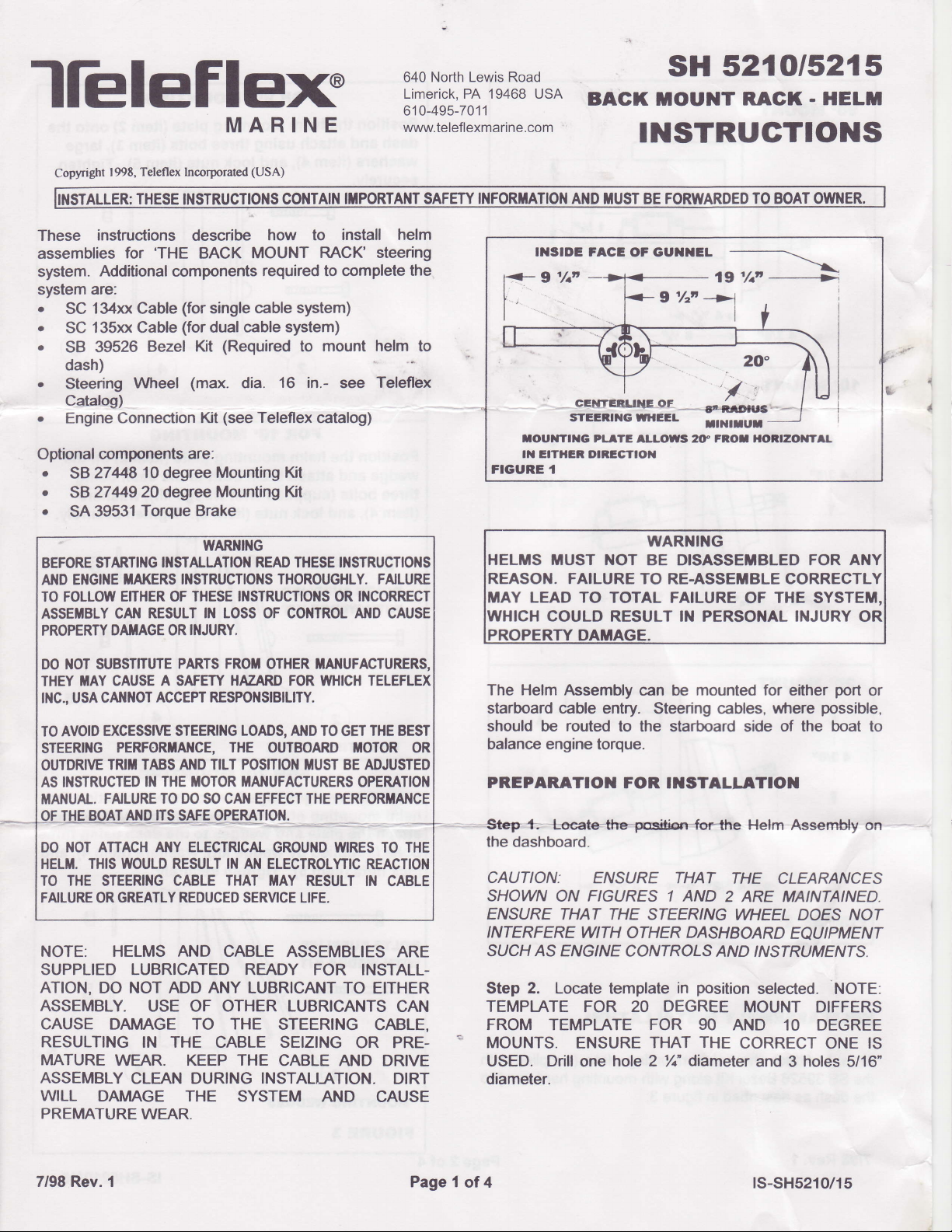
IIISIDE FACE
OF GUIIIIEL
,,r'r};
9'/zi'->1
7"*
cEilTqtxE_gE
STEIiII{G ITIEEL
fOUttlTlXG PL TE ILLOWS 20" FROI IIORIZO]|TTL
tt{ EtTHEn DtRlcTtox
FIGURE 1
i'UST
. FAILURE TO
Y LEAD TO
COULD
|
WARNING
NOT BE DISASSETBLED FOR
RE.ASSETIBLE CORRECTL
TOTAL FAILURE
RESULT IN PERSONAL INJURY
I
20
''/:
rtE.ruc'-__
IINIIUT
OF
THE
DO iIOT
THEY
IilC.,
TO AVOID
STEERITIG
OUTDRIVE
AS INSTRUCTED
MANUAL. FAILURE
DO NOT ATTACH ANY ELECTRICAL
HELM. THIS WOULD RESULT IltI AliI ELECTROLYTIC
TO THE
FAILURE OR GREATLY
SUBSTITUTE
MAY CAUSE
CAI{}IOT ACCEPT RESPONSIBILITY.
USA
EXCESSIVE STEERING LOADS, AI{D TO GET THE BEST
PERFORTAI{CE,
TRIT TABS AND TILT POS]TIO]{ ]TIUST 8E ADJUSTED
STEERING CABLE
NOTE: HELMS AND CABLE
PARTS FROT
A SAFETY HAZARD FOR WHICH TELEFLEX
IN THE TIOTOR MANUFACTURERS
TO DO
SO
REDUCED
OTHER ITAIIUFACTURERS,
THE
OUTBOARD TIOTOR OR
OPERATION
CAI{ EFFECT THE
GROUiID WIRES TO THE
THAT MAY
SERVICE LIFE.
PERFORTANCE
RESULT IN
REACTION
CABLE
ASSEMBLIES ARE
SUPPLIED LUBRICATED READY FOR INSTALLATION,
ASSEMBLY.
CAUSE DAIVIAGE TO THE
RESULTING
MATURE
ASSEMBLY
WILL
PREMATURE
DO NOT ADD ANY LUBRICANT
USE OF OTHER LUBRICANTS
STEERING
IN THE CABLE SEIZING
WEAR. KEEP THE
CLEAN DURING
DAMAGE
THE SYSTEM AND
CABLE AND DRIVE
INSTALTATION.
WEAR
TO EITHER
CAN
CABLE,
OR PRE-
DIRT
CAUSE
The Helm Assembly
starboard
should
balance
PREPARATIO]I
Stsp+-
cable
entry. Steering cables,
be routed
to the starboard side of the
engine torque.
FOR I]ISTALLATIO]I
@
can be
mounted for
the dashboard.
CAUTTON:
SHOWN
ENSURE
INTERFERE
SUCH AS ENGINE COA'IROLS
Step 2. Locate template
E/VSURE THAT
ON FIGURES 1 AND
THAT THE STEERING
WITH
OTHER
DASHBOARD
AND'NSTR
position
in
THE
2 ARE MAINTAINED.
TEMPTATE FOR 20 DEGREE
FROM
TEMPTATE
MOUNTS.
USED. Drill
ENSURE
one
FOR 90
THAT
hole 2
THE
dlameter
/t"
AND
diameter.
port
where
Helm
either
possible,
Assemtily on
boat
or
to
CLEARANCES
WHEEL DOES NOT
EQUIPMENT
UMENTS.
selected. NOTE:
MOUNT DIFFERS
10 DEGREE
CORRECT
ONE
IS
and 3 holes 5/16"
7/98 Rev. 1
Page 1
of4
ts-sH5210/15
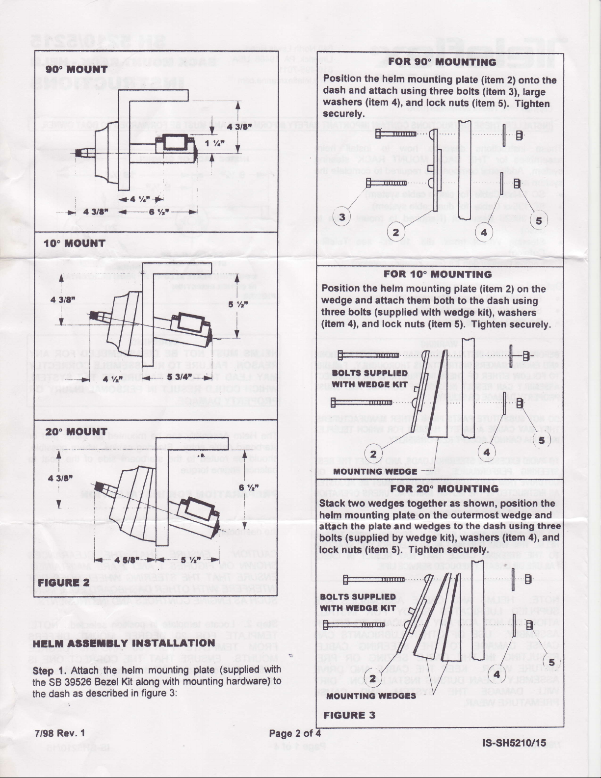
FOR
Positlon
dash
washers (item
securely.
the
helm
and attach
90" ilOutrtT|ltG
mounting
using three
4),
and
lock nuts
plate
bolts
(item
(item
(item
S).
2)
onto
large
3),
Tighten
the
Fr@
-1
€)
Poeition
wedge
three
(item
and aftach
bolts
4),
E=:-',,gI-
roLrsruPPLED
wrTHwtDoar.TJil,t
o:::::m
tout{Tt1{o,uutDot
,
Stack two
helm mounting
attfch
bolts
lock nuts
the
(supplied
,n/"
\2)
the helm mountlng
(supplied
lock
and
nuts
-'r"-
i2\ !
FOR 20' TOUNTING
wedges
plate
plate
and
wedge kit), washers
by
(item
5).
q
f"l
Ia
*\
illl ,r
u,{
(4)
plate
(item
2) on the
them both to the
with wedge
(item
5). Tlghten
{l A ll
Ih Il I I
illl /lll tt
Ir, I tt r
u| | /
T
IJ
I
---
together as shown,
on the
wedges
Tighten
outermost wedge and
to the daeh using three
securely.
dash using
kit),
nn
tl
u,'{,
iet
. ,
washers
securely.
hB-
position
(item
q
\
(:)
\
(s.i
the
cn the
e and
rg
three
4),
4),
and
and
Ftcunl 2
HCTTI
Step
the SB
the
7198 Rev.
AiIEf,ETY
Attach
1.
39526
dash as
the helm
Bezel Kit
described
I
I]IITALLATION
mounting
along
figure 3:
in
with
plate
mounting
(supplied
hardware)
with
to
Page 2 of
tur7{lllll
loLrs 'uPPLTED
/1 | | Il I I
H*llllllll
I|| i
toulrTDac
FIGURE 3
4
/ftil
,/ Ytr,U,1
(z\
-,-/ \ /
wrDcls
\/
nn
E
ll
nH
(.4)
ts-sH5210/15
\
(S
 Loading...