

Teleflex Marine KE-4 Installation/operation Instruction Manual

KE-4 FT033
Installation/Operation
Instruction Manual


Electronic Control System
Electronic Control System
Thumb Tab Guide
Trolling Module Handheld Control Engine Synchronization
Trolling Module
Handheld Control
Engine Synchronization


Electronic Control System
Electronic Control System
TABLE OF CONTENTS
Introduction .....................................................................................................1
Basic Performance .........................................................................................2
Name Of Each Part ........................................................................................3
Components ...................................................................................................4
Name And Function Of Control Unit Components ..........................................5
Name And Function Of Control Head Components .......................................6
Name And Function Of Actuator Components ................................................7
How To Operate ...............................................................................................8
1. Initial operation after power ON ........................................................................... 8
2. When the control head connected to R/C-1 is to be used first ............................. 8
3. When the control head connected to others than R/C-1 is to be used first ........... 8
4. Shift throttle operation ........................................................................................... 8
5. Neutral throttle operation ...................................................................................... 9
6. Station transfer ...................................................................................................... 9
Determination Of Cable Length ....................................................................10
Installing The Control Head .......................................................................... 11
Installing The Control Unit ............................................................................12
Installing The Actuator ..................................................................................13
Connecting The Control Head And Control Unit ............................................14
Connecting The Actuator And Control Unit ...................................................15
Connecting The Neutral Switch Harness ......................................................16
Connecting The Harness Power Supply ........................................................17
Connecting The Communication Harness .................................................... 18
Connecting The Dim Harness ......................................................................19
Overall Wiring Diagram ................................................................................20
Cable Installation ...........................................................................................21
1. Cable installation to the actuator ........................................................................21
2. Cable installation to the engine ..........................................................................22

Electronic Control System
Adjusting The Control Unit .............................................................................23
1. Setting the throttle actuator operation direction ..................................................24
2. Setting the forward throttle actuator stroke .........................................................24
3. Setting the throttle actuator stroke opening ........................................................24
4. Setting the reverse throttle actuator stroke .........................................................25
5. Setting the shift actuator operation direction .......................................................25
6. Setting the shift actuator stroke ..........................................................................25
7. Setting the throttle delay ....................................................................................26
8. Setting the shift pause ........................................................................................26
Operation Check ..........................................................................................27
1. Shift and throttle operation check ......................................................................27
2. Confirmation of the engine start .........................................................................27
Manual Operation Method ............................................................................28
Alarm Indication ............................................................................................29
Check Points In Case Of Trouble ..................................................................32
Maintenance And Service ..............................................................................33
Control Head Template .................................................................................35
Control Unit Template ...................................................................................37
Electronic Control System 1
Electronic Control System
INTRODUCTION
This manual has been prepared to ensure your correct operation of the KE-4 system. Be sure to read
this manual thoroughly to understand the contents to prevent injury or damage to the property through
abuse. Always keep the manual within your reach during operation.
This product controls the shift (clutch) and throttle (governor). It is recommended therefore to read
the manual of engine and clutch.
The specifications may be subject to change without notice in view of improvement, resulting in
more or less difference between the content of the manual and the product. In case of ambiguity
or questions concerning the product or the manual, consult with your dealer.
SAFETY PRECAUTIONS
This manual contains precautions under the following headers, which, if not observed, may result
in injury or damage to the property. Pay particular attention to these precautions.
WARNING
Failure to comply with a Warning may result in an accident or death or heavy injury.
CAUTION
Failure to comply with a Caution may result in an accident of light injury or damage to the
product or properties.

2 Electronic Control System
Electronic Control System
BASIC PERFORMANCE
1. Electric Performance
a. Supply voltage
For DC12V model:DC9V~16V
For DC24V model:DC16V~3OV
b. Max. current of actuator:16A or less(at 49N{5kgf}load)
c. Current consumption at stop of actuator: 0.5A or less
2. Performance of Actuator
a. Thrust
Maximum operating thrust:147N{15kgf}
Constraint load :343N{35kgf}
b. Stroke
Shift: Forward stroke 26 • 30 • 34 • 40mm
Shift: Reverse stroke 26 • 30 • 34 • 40mm
Shift: Forward and reverse strokes can be set separately.
Throttle: Max. 80mm
3. Temperature Range
a. Operating temperature:-20~+75°C
b. Storage temperature :-40~+lOO°C
4. Principal Functions
a. Shift: Forward/reverse operation
b. Throttle: Acceleration/deceleration
c. Neutral throttle: Only the throttle is activated to warm up the engine.
d. Control Station:Max.4 stations
e. Neutral safety switch: Enables engine start up only when the shift is in the neutral position.
f. Dim display:Decreases illuminance of the lamp on the control head at night.
g. Fault indication: Detect system faults and indicate by the frequency of flashing of the
pilot lamp of the control head.
h. Mechanical back-up: Enables mechanical operation of the actuator when the system failure
makes operation from the control head impossible.
Electronic Control System 3
Electronic Control System
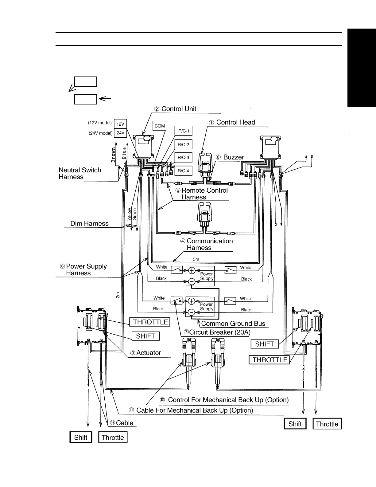
NAME OF EACH PART
The figure below shows an example of two engines/two control station system.
: Indicates identification
: Indicates the destination of connection
10M
10M

4 Electronic Control System
Electronic Control System
Required
Single Engine Two Engines Note:
No. of Station No. of Station
No. Name Part No. 1st 2nd 3rd 4th 1st 2nd 3rd 4
th
➀ Control Head NM0511-00 1 2 3 4 — — — —
NM0510-00 — — — — 1 2 3 4
➁ Control Unit
24 V Model NM0478-00
12V Model NM0477-00
1 1 1 1 2 2 2 2
➂ Actuator NM0165-00 1 1 1 1 2 2 2 2
➃ Communication
Harness 5m
NM0619-05 — — — — 1 1 1 1
➄ Remote Control
Harness
4m NM0616-04
6m NM0616-06
8m NM0616-08
10m NM0616-10
12m NM0616-12
14m NM0616-14
16m NM0616-16 1 2 3 4 2 4 6 8
18m NM0616-18
20m NM0616-20
24m NM0616-24
30m NM0616-30
38m NM0616-38
40m NM0616-40
50m NM0616-50
➅ Power Supply
Harness 10m NM0414-33 2 2 2 2 4 4 4 4
➆ Circuit Breaker
20A NJ0514-00 2 2 2 2 4 4 4 4
➇ Buzzer
12V Model NJ0251-00
24V Model NJ0515-00 1 2 3 4 2 4 6 8 Option
➈ Cable CC633XX Specify
33C Supreme 2 2 2 2 4 4 4 4 length
➉ Mechanical Use standard
Control Head control head 1 1 1 1 2 2 2 2 Option
Cable (for CC633XX Option
manual 33C Supreme 2 2 2 2 4 4 4 4 specify
operation) length
Refer to the name of each part on page 3.
Note: 1 meter = 39 inches
COMPONENTS
Electronic Control System 5
Electronic Control System
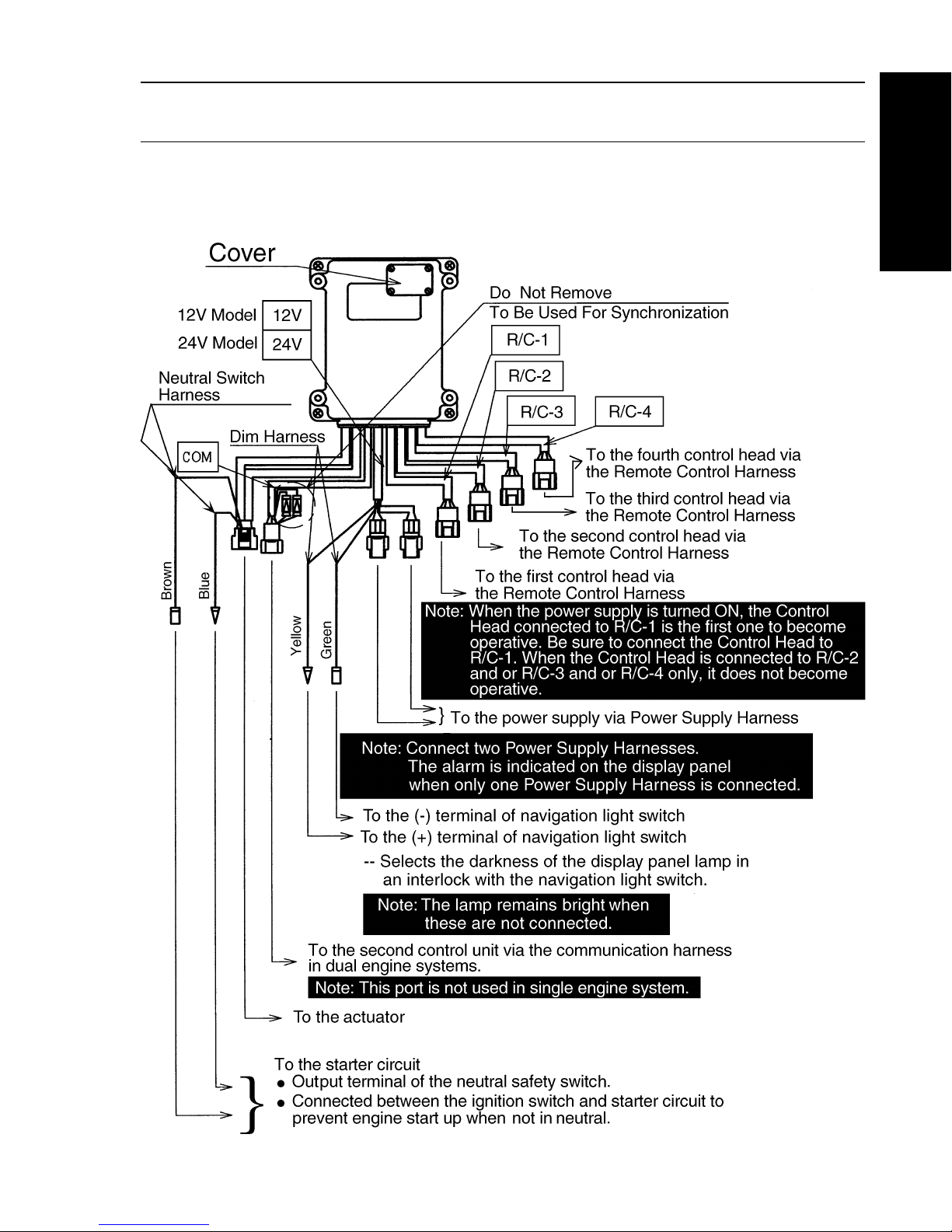
NAME AND FUNCTION OF
CONTROL UNIT COMPONENTS
Note: The Control Unit is available in two types, one for 24V and the
other for 12V. Select the appropriate one for your power supply.
6 Electronic Control System
Electronic Control System
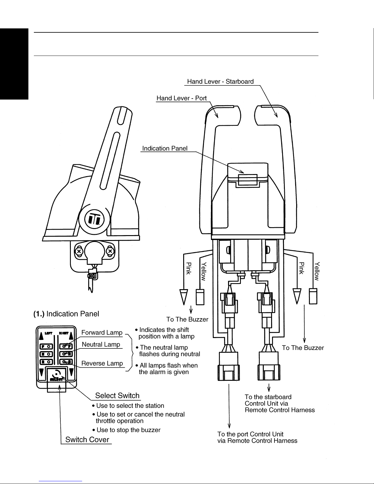
NAME AND FUNCTION OF
CONTROL HEAD COMPONENTS
Electronic Control System 7
Electronic Control System
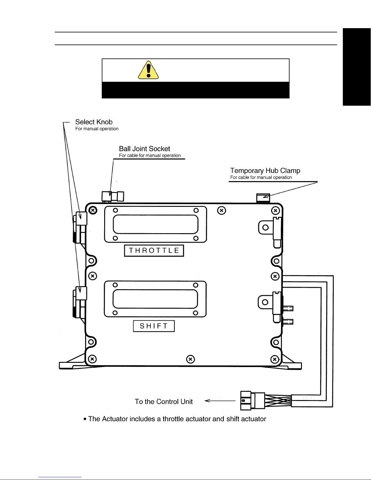
NAME AND FUNCTION OF ACTUATOR COMPONENTS
WARNING
Never operate the Selector Knob except
in case of emergency.
Note: Actuator harness cannot be extended or changed.
8 Electronic Control System
Electronic Control System
1. Initial operation after power ON
With power ON, the throttle actuator is fully closed and the shift actuator is set to
neutral.
2. When the control head connected to R/C-l is to be used first
a. Set the hand lever to the neutral position.
b. The neutral lamp goes ON and the control head becomes operative.
3. When the control head connected to others than R/C-l is to be used first
a. Set the hand lever to the neutral position.
b. Open the switch cover and press the selector switch.
c. The neutral lamp goes ON and the control head becomes operative.
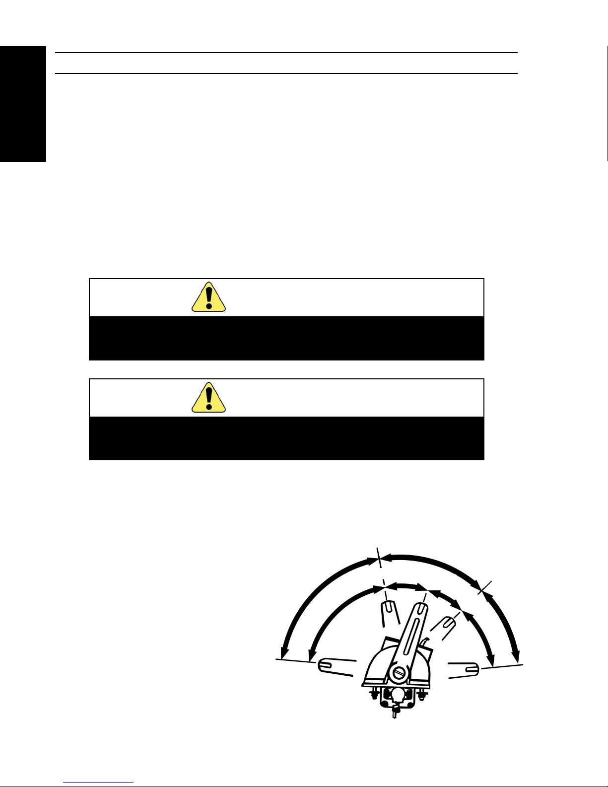
4. Shift and throttle operation
a. Shifting the hand lever from the neutral position to the forward detent causes the
shift actuator to operate in the forward direction.
(Forward lamp ON)
Shifting the lever further
in the forward direction causes the
throttle actuator to accelerate.
b. Shifting the hand lever from the
neutral position to the reverse
detent causes the shift actuator
to operate in the reverse direction.
(Reverse lamp ON)
Shifting the lever further in
the reverse direction causes
the throttle actuator
to accelerate.
Never attempt sudden hand lever operation at high engine
speed. It may cause damage to the clutch or transmission.
Never ope r ate th e hand leve r whil e the en g ine is
stopped. Otherwise, the actuator, cable and engine may
be damaged.
HOW TO OPERATE
CAUTION
WARNING
Throttle
Idle
Shift
Idle
Throttle
75°
Forward
25°
25°
Reverse
45°
Forward
Full Throttle
Reverse
Full Throttle
Neutral

Electronic Control System 9
Electronic Control System
5. Neutral throttle operation
How to set
a. Set the hand lever to the neutral position.
b. Open the switch cover and shift the hand lever to the forward position while pressing the
selector switch.
c. The neutral lamp flashes and the neutral throttle operation can be made.
How to cancel
a. Set the hand lever to the neutral position.
b. Open the switch cover and press and release the selector switch.
c. The neutral lamp goes ON and shift and throttle operations can be made.
6. Station transfer
a. Set the hand lever(s) of the desired control head to the neutral position, when transferring
control station. The hand lever(s) of the active station may be in any position.
When transferring control station, both the port and starboard hand lever of the
desired control head must be in the neutral position in dual engine system.
b. Open the switch cover and press the selector switch.
c. The light(s) goes ON and the desired control head is ready to use. At the same time, the
throttle and shift actuator return to the neutral position at 4 seconds from the full
throttle position. This allows the operator to move the hand levers to match the new
position as the actuator moves back to that position.
10 Electronic Control System
Electronic Control System
DETERMINATION OF CABLE LENGTH
Do not bend the cable less than the specified radius.
Otherwise, the cable or actuator may suffer early damage.
CAUTION
Measure the distance from the shift and throttle actuator to the engine’s shift and throttle connection
position, measuring as straight as possible while avoiding any obstruction which may cause bending
of less than the specified radius.
This distance becomes a guideline to determine the cable length.
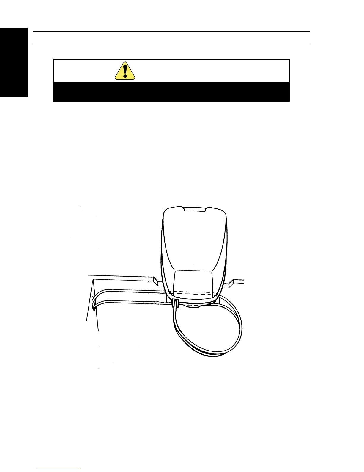
For the outboard motor
Determine the cable length as determined above plus 1-1.5m (4 feet) to make up a loop shown
below.
Electronic Control System 11
Electronic Control System
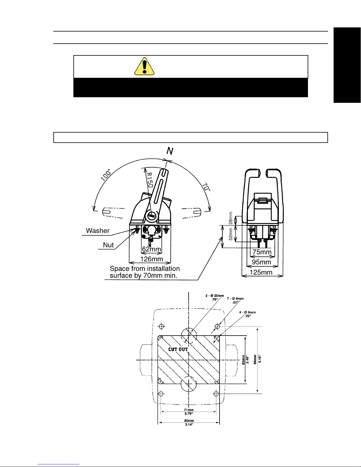
INSTALLING THE CONTROL HEAD
Install the control head in an accessible place where the
engine can be stopped anytime.
CAUTION
Select a flat place convenient for operation and installation.
a. Drill mount holes by using an attached template.
b. Install with attached washer and nut.
Tightening torque: 2.9~4.4N•n {30~45kgf • cm}
12 Electronic Control System
Electronic Control System
Ingress of water into the unit may cause failure
1. Install so that the harness comes from the
bottom side.
2. Install in a place free from effect of the sea
breeze and seawater.
Avoid a place where the ambient temperature rises
above 75° C.
CAUTION
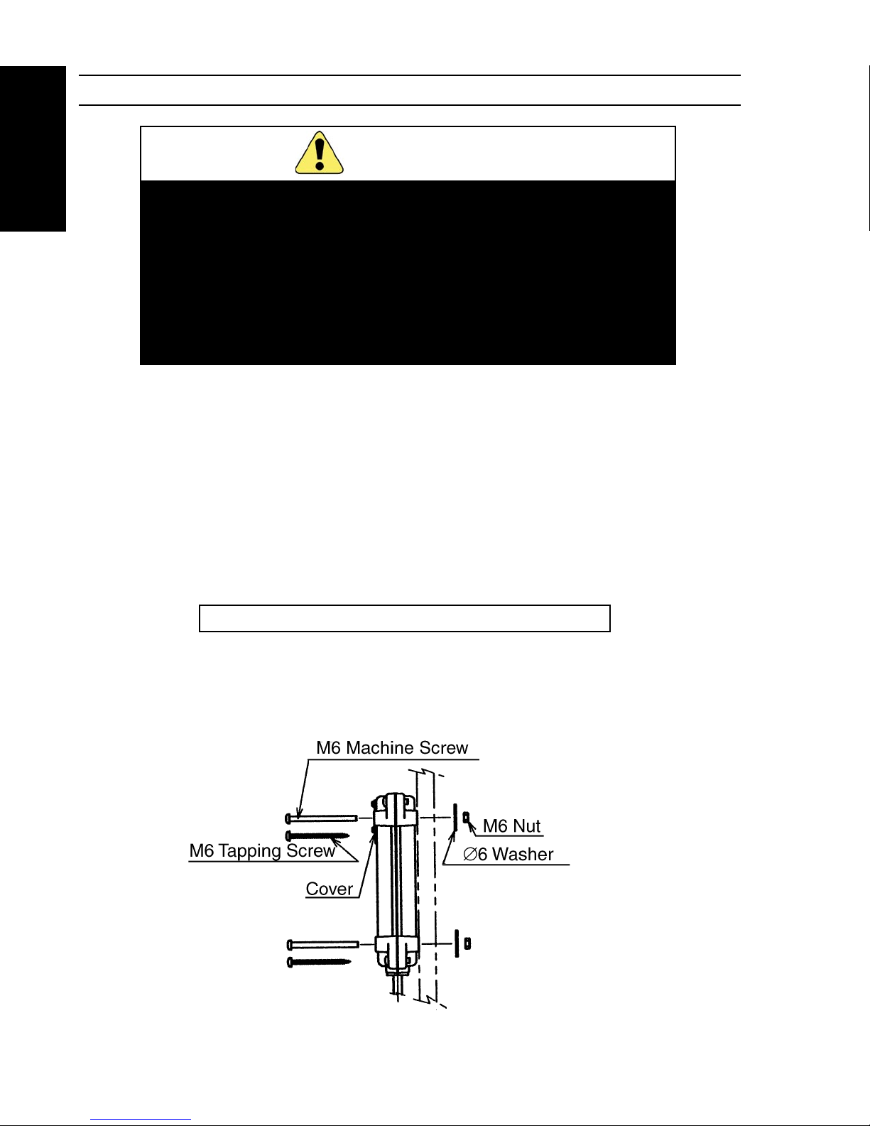
INSTALLING THE CONTROL UNIT
Note: Actuator harness cannot be lengthened or changed.
Note: Install the control unit so that the cover comes in front.
1. The actuator harness is 2m in length. Select the control unit location so that its distance
from the actuator is 2m or less.
2. Drill the mount hole by using an attached template.
3. Install with attached pan head machine screw or tapping screw.
Installation with pan head machine screw
Installation plate thickness: 3~ 20mm
Mount hole dia: ∅ 7 mm
Tightening torque: 4 .9 ~ 7 .8N•m { 5 0~ 80 kgf •c m}
Installation with tapping screw
Installation plate thickness: 15mm Min.
Pilot hole dia : ∅ 3 mm
Electronic Control System 13
Electronic Control System
Ingress of water into the unit may cause failure.
Install in a place free from effect of the sea breeze and
seawater. Avoid a place where the ambient temperature
rises above 75°.
CAUTION
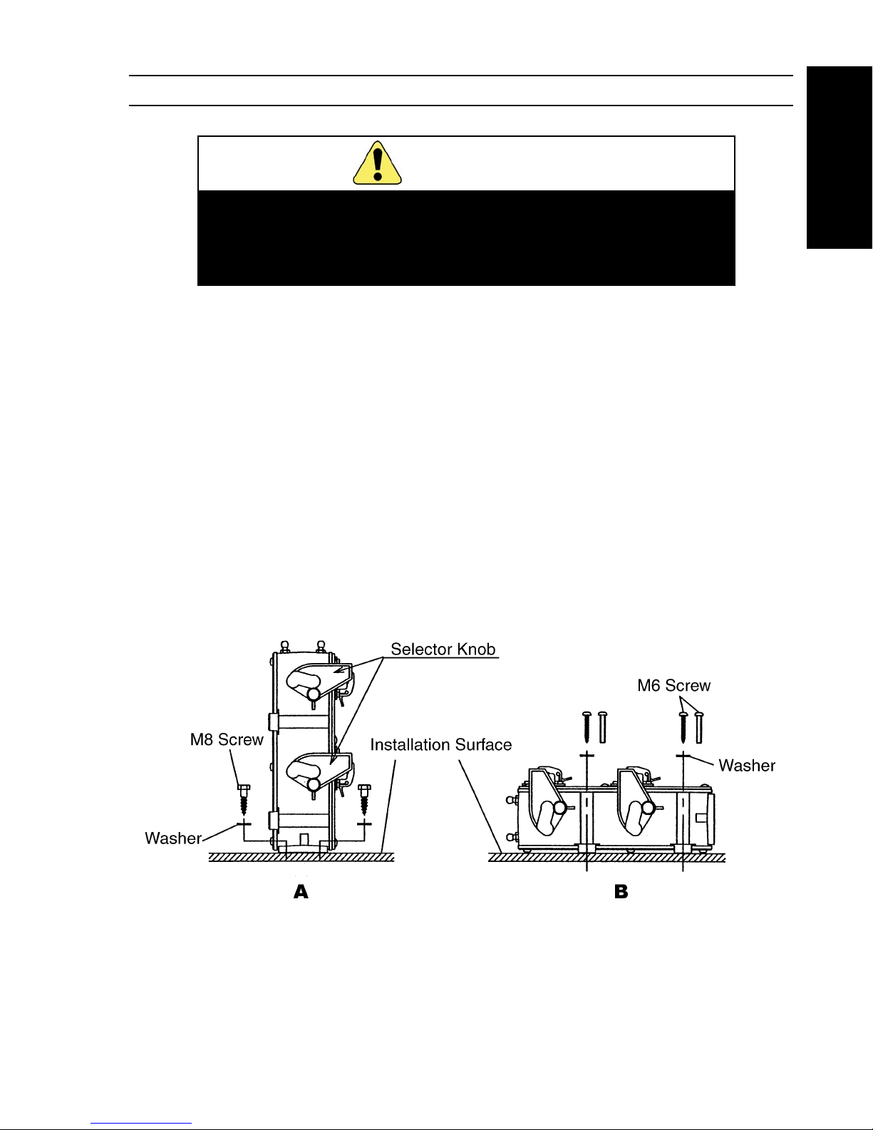
INSTALLING THE ACTUATOR
1. Install the actuator in a place convenient for operation of manual selector knob.
2. The actuator harness is 2m in length. Select the control unit location so that its distance from
the actuator is 2m or less. (The actuator harness cannot be lengthened or changed.)
3. Drill the mount hole by using an attached template.
4. Install with four attached screws and washers as shown below left (A).
Installation plate thickness: 20mm Min
Pilot hole dia : ∅ 5mm
Note: Another installation is available using suitable M6 machine
screw or M6 tapping screw and washer as shown below right (B).
• Screws and washers for this installation are not attached.
14 Electronic Control System
Electronic Control System
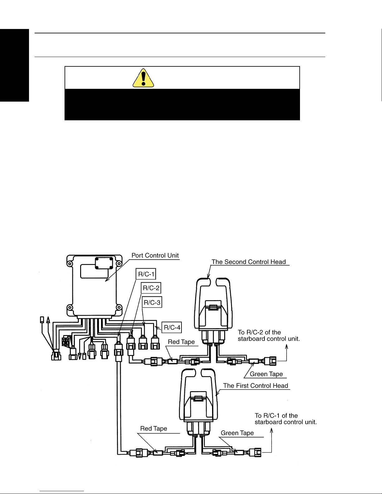
CONNECTING THE CONTROL HEAD
AND CONTROL UNIT
Connect the coupler firmly.
These units may fail to operate when the coupler is
not connected firmly.
CAUTION
1. Connection of the first control head
• Connect the harness remote control to the red-taped harness of the control head and
connect it to the R/C-l of the port control unit.
• Connect the harness remote control to the green-taped harness of the control head and
connect it to the R/C-l of the starboard control unit.
Note: Be sure to connect the control head to the R/C-l of the each
control unit.
2. Connection of the second control head if applicable
• Carry out connection to the R/C-2 the each control as described in (1).
3. Connection of the third control head if applicable
• Carry out connection to the R/C-3 the each control as described in (1) .
4. Connection of the third control head if applicable
• Carry out connection to the R/C-4 the each control as described in (1) .
Electronic Control System 15
Electronic Control System
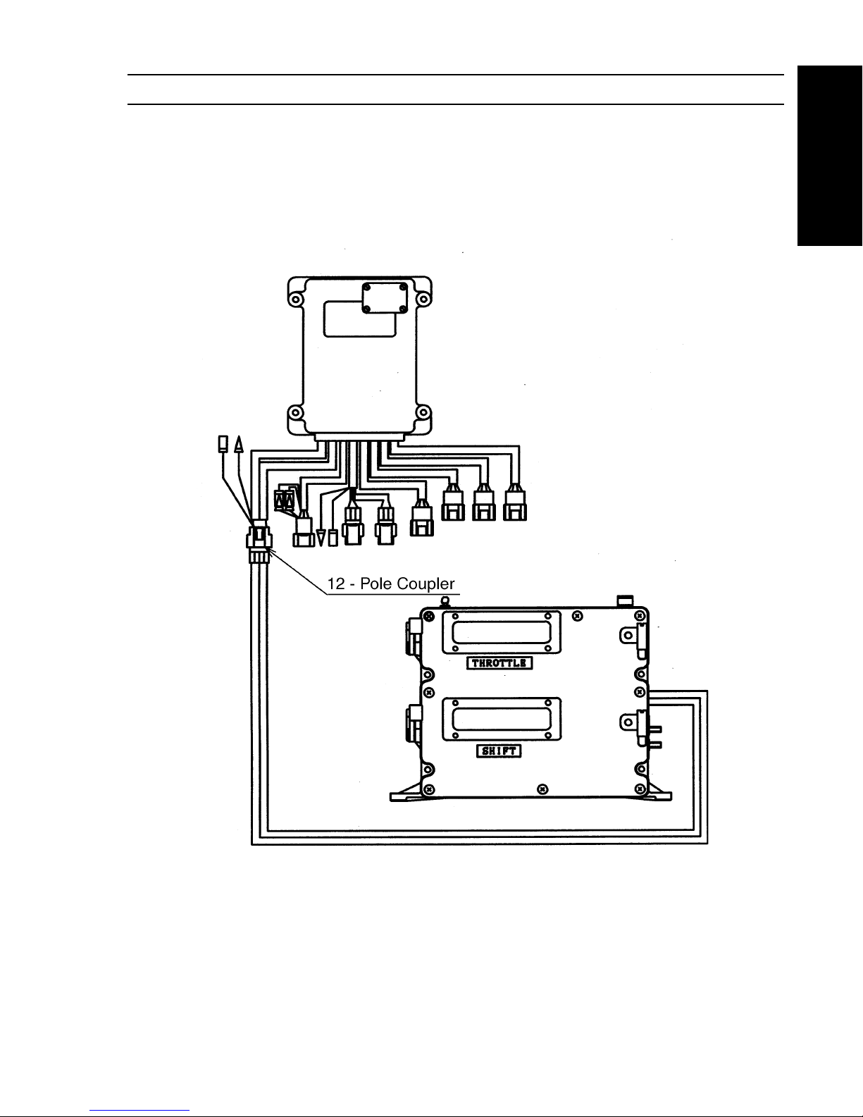
CONNECTING THE ACTUATOR AND CONTROL UNIT
Connect a 12 - pole coupler of the actuator to that of the control unit.
16 Electronic Control System
Electronic Control System
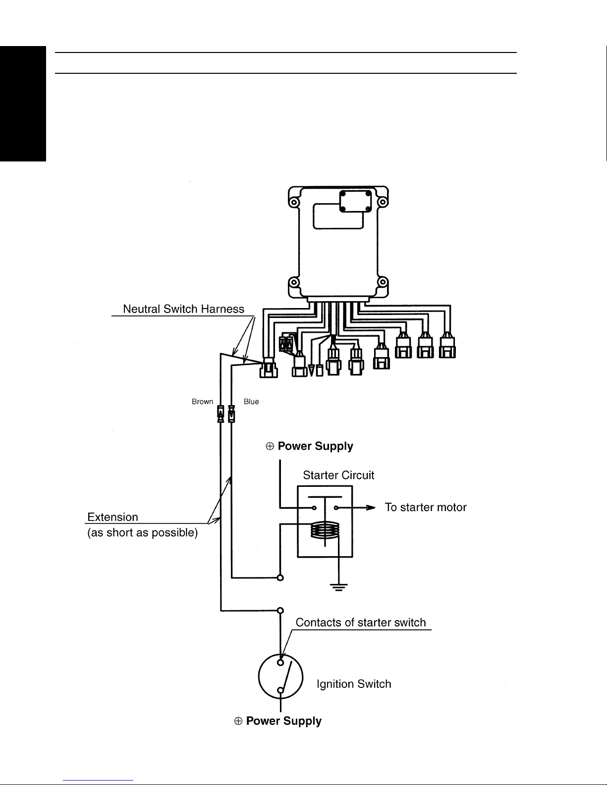
CONNECTING THE NEUTRAL SWITCH HARNESS
Connect the neutral switch harness between the starter circuit.
Note: Use a thick (2mm or more) and short extension for the neutral
switch harness. Long extension may cause voltage drop,
resulting in failure of engine start.
Electronic Control System 17
Electronic Control System
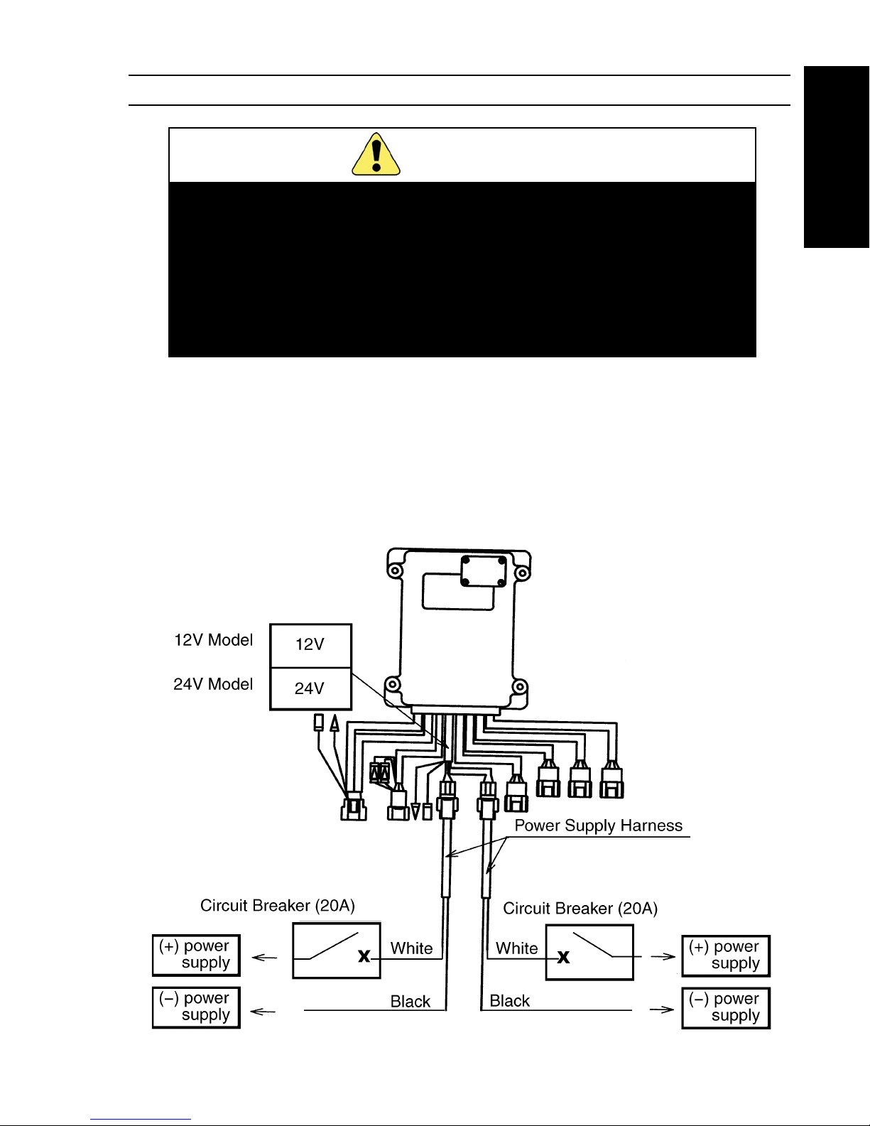
CONNECTING THE POWER SUPPLY HARNESS
To ensure safety, the duplex power line system is provided. Be
sure to connect both lines.
The display panel shows an alarm message when only one
power line is connected.
Do not disconnect the power harness from the control unit after
connected the power harness with battery (power supply).
Use circuit breaker or battery switch to turn off the power.
CAUTION
1. Connect the Power Harness with the control unit before connecting each power harness with
battery (power suppply) .
2. Connect each black wire of the power harness directly to (-) of battery (power supply).
3. Connect each white wire of the power harness via a 20 amp circuit breaker or fuse to (+) of
battery (power supply) .
Note: If two or more batteries are provided, connect each power switch.
18 Electronic Control System
Electronic Control System
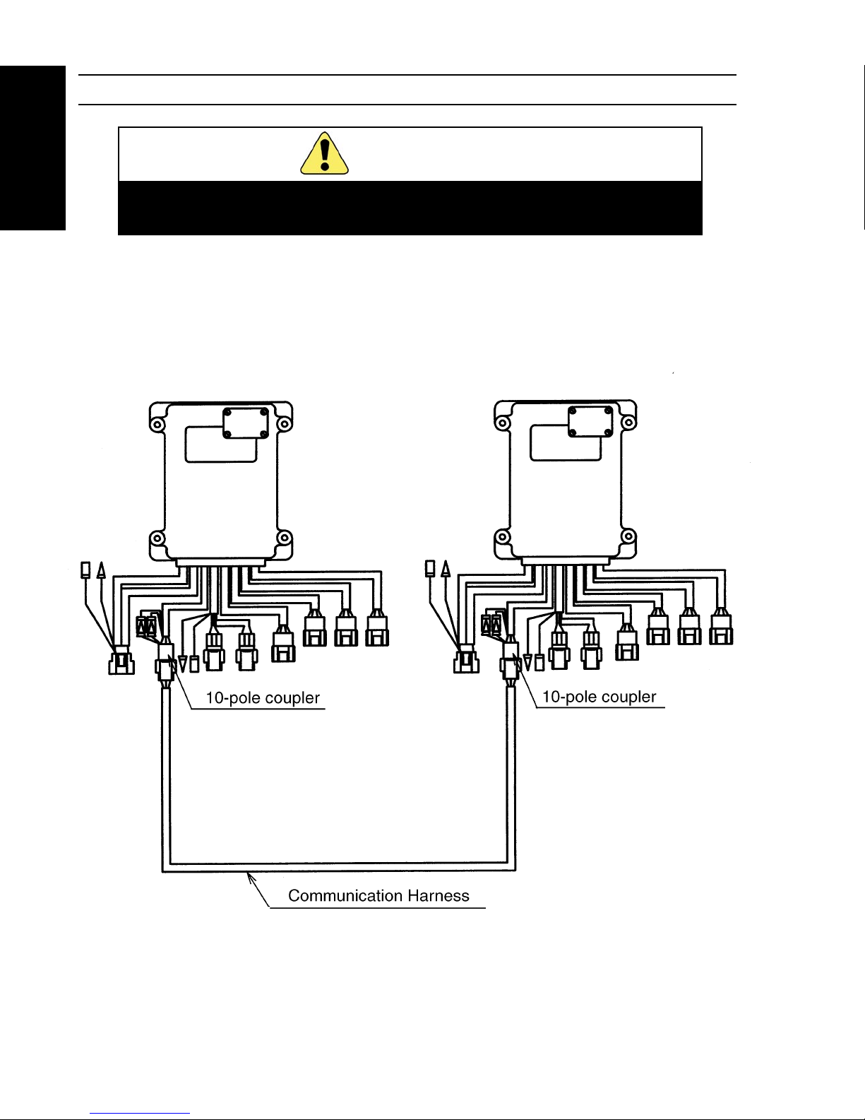
CONNECTING THE COMMUNICATION HARNESS
Turn off circuit breaker or battery switch before connecting or
disconnecting the communication harness to the control unit.
CAUTION
Connect the two control units by the communication harness, which has 10-pole couplers at both
ends, in dual engine system.
Electronic Control System 19
Electronic Control System
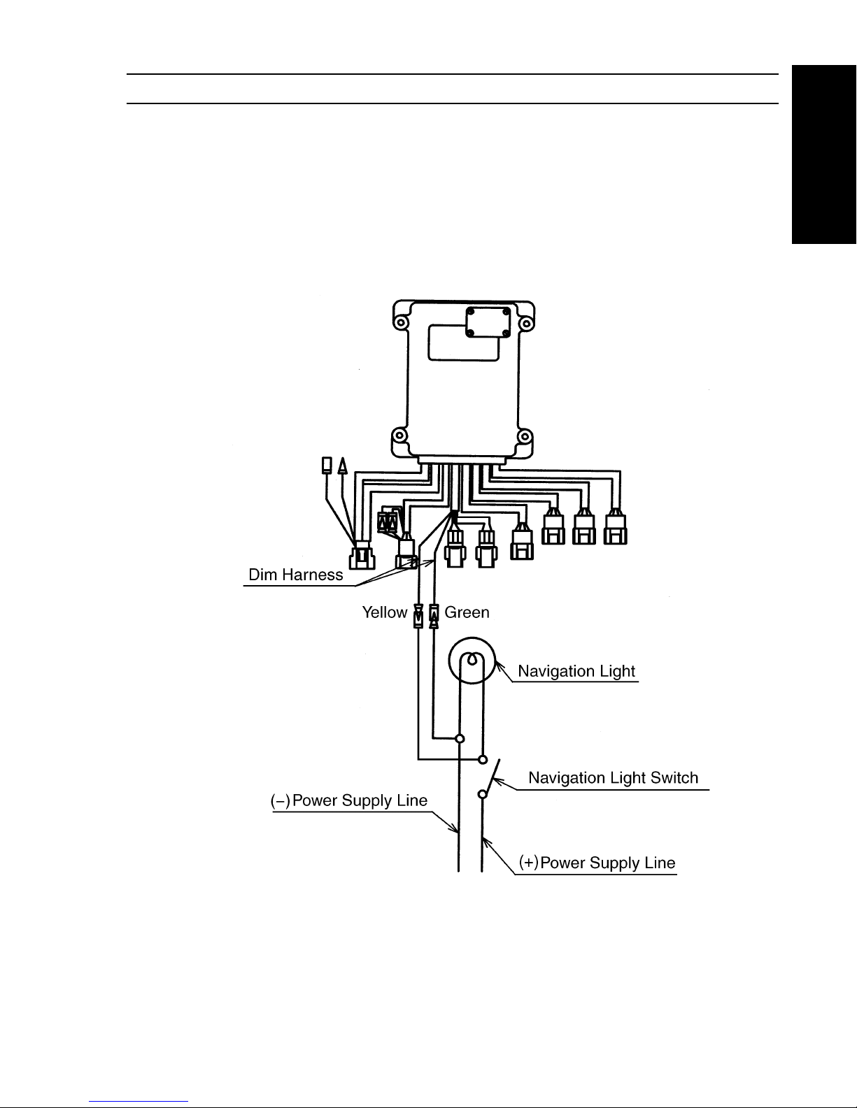
CONNECTING THE DIM HARNESS
1. Connect the Dim Harness yellow line to the (+) wire of navigation light.
2. Connect the Dim Harness green line to the (-) wire of navigation light.
Note: The Dim Harness connection is not mandatory.
20 Electronic Control System
Electronic Control System
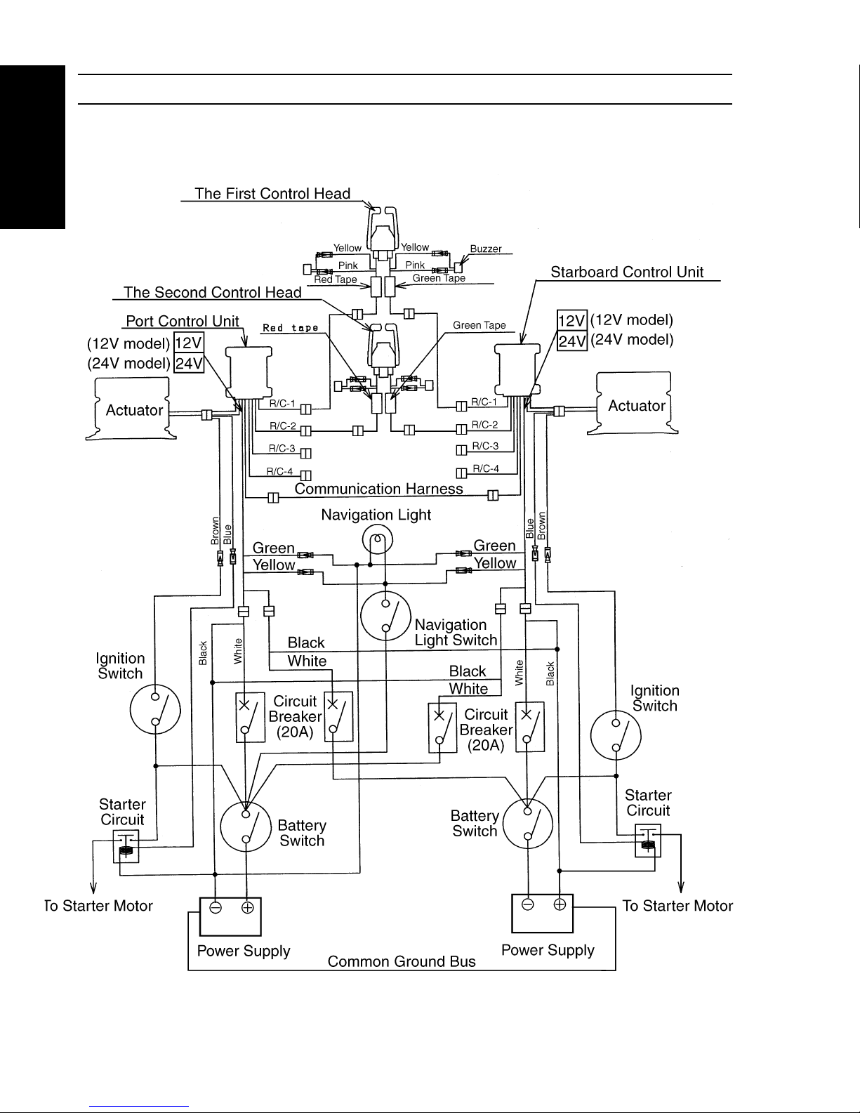
OVERALL WIRING DIAGRAM
The diagram below shows a case with two engines operated from two control heads.
Electronic Control System 21
Electronic Control System
CABLE INSTALLATION
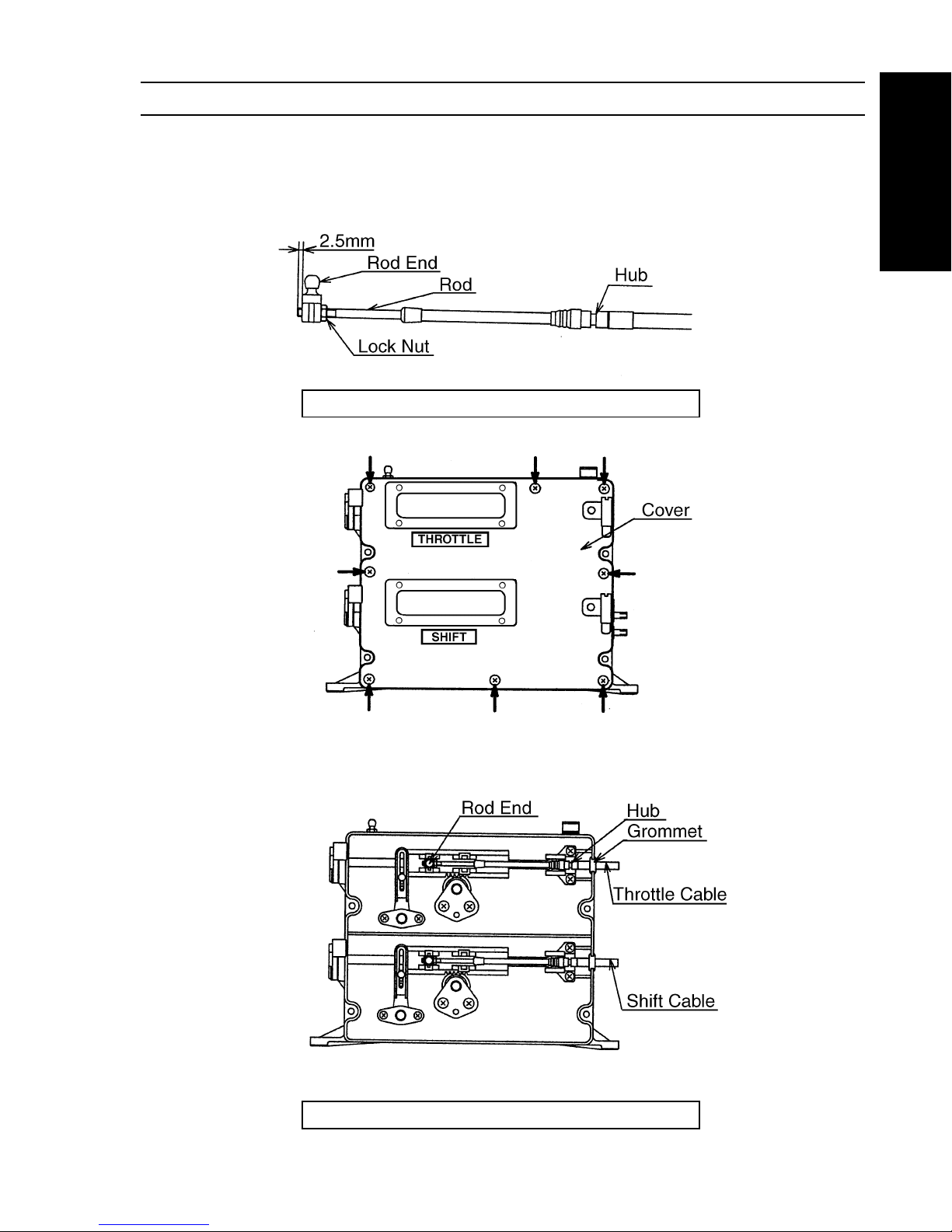
1. Cable installation to the actuator
Cable installation method is similar for both shift and throttle.
a. Install an attached rod end to the rod and fix with lock nut.
Tightening torque:2. 9~4. 4N • m {30~45kgf • cm}
b. Remove eight actuator screws shown with arrow and remove the cover.
c. Install waterproof grommet to the cable.
Install the rod end, hub, waterproof grommet to the actuator mount groove as shown
below.
d. Install the cover to the actuator with screws.
Tightening torque: 1. 2~1. 8N • m {12~18kgf • cm}

22 Electronic Control System
Electronic Control System
2. Cable installation to the engine
Note: Carry out cable installation when connection of all harnesses
is completed.
a. Carry out positioning of the actuator as follows:
Positioning the actuator
• Turn ON power.
• Set the control head connected to R/C-1 to the neutral position.
• The throttle actuator is fully closed and the shift actuator comes to the
neutral position.
• Positioning is completed when the neutral lamp goes ON.
b. Install the cables according to the engine instruction manual.
CAUTION
Install the cable first to the actuator, then
to the engine.
CAUTION
Be sure to turn OFF power supply to the
control unit before installation of the cable
to the engine.
Electronic Control System 23
Electronic Control System
Turn OFF the power and remove the cable from the trolling valve.
Then, carry our positioning of the actuator. (See page 22)
After adjustment, install the cover.
Tightening torque: 1.0~.7N•m
ADJUSTING THE TROLLING UNIT
CAUTION
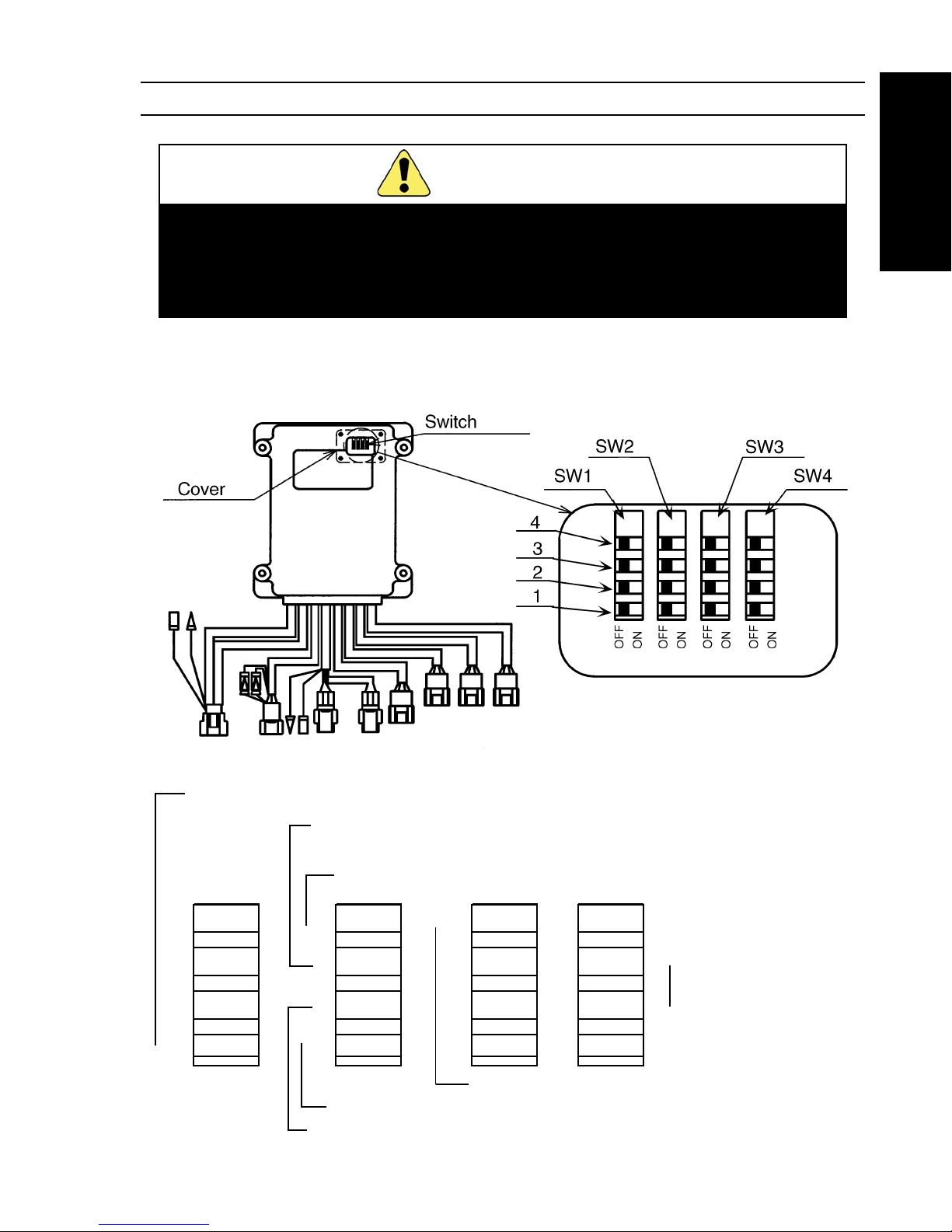
When the actuator operation is not matched with the trolling valve, adjust by the switch in the trolling
unit as follows.
Remove the cover, and the switch can be operated.
SW1-4
SW1-3
SW1-2
SW1-1
SW2-4
SW2-3
SW2-2
SW2-1
SW3-4
SW3-3
SW3-2
SW3-1
SW4-4
SW4-3
SW4-2
SW4-1
→
→
→
→
→
→
→
→
→
→
→
→
→
→
→
List of switch functions
Forward throttle actuator stroke (page 24)
Reverse throttle actuator stroke (page 25)
Reverse throttle opening (page 25)
Throttle actuator operation mode (page 24)
Shift actuator stroke (page 25)
Shift pause (page 26)
Shift actuator operation mode (page 25)
→
Throttle delay (page 26)
Forward throttle opening (page 24)
24 Electronic Control System
Electronic Control System
1. Setting the throttle actuator operation mode
Set whether the trolling valve is shifted to the disengage by pushing out the cable or by pulling
in the cable. (Confirm on the rolling valve side).
Set with SW2-1.
* Before shipment, the switch is set to OFF (Pull to open throttle).
2. Setting the forward throttle actuator stroke
The throttle actuator stroke when the hand lever is operated from the forward detent to the
forward full open position can be set from 31mm to 73mm in a 3mm interval and 80mm.
Set with SW1-1 • 2 • 3 • 4.
* Before shipment, the switch is set to OFF (64mm stroke).
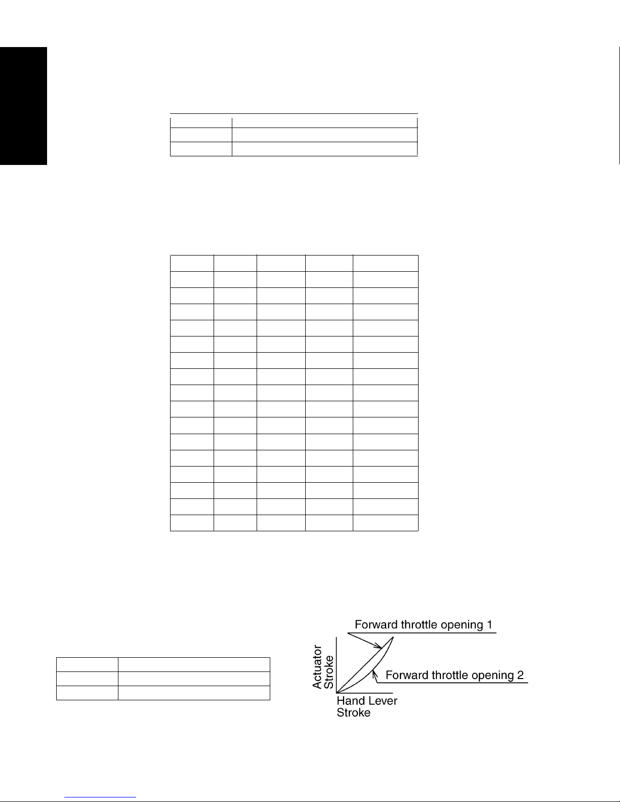
3. Setting the throttle actuator stroke opening
This function facilitates fine throttle adjustment over range from idle to low RPM range.
This setting also allows decrease in the shock after shift in when the hand lever is operated
suddenly.
a. Setting the forward throttle opening
Set with SW2-2.
* Before shipment, the switch is set to OFF (Opening 1).
SW2 — 1 FUNCTION
OFF Pull to open Throttle
ON Push to open Throttle
SW2—2 FUNCTION
OFF Forward throttle opening 1
ON Forward throttle opening 2
SW1-1 SW1-2 SW1-3 SW1-4 STROKE
ON OFF ON ON 31mm
ON OFF OFF ON 34 mm
ON OFF ON OFF 37mm
ON OFF OFF OFF 40mm
OFF ON ON ON 43mm
OFF ON OFF ON 46mm
OFF ON ON OFF 49 mm
OFF ON OFF OFF 52mm
OFF OFF ON ON 55mm
OFF OFF OFF ON 58mm
OFF OFF ON OFF 61mm
OFF OFF OFF OFF 64mm
ON ON ON ON 67mm
ON ON OFF ON 70mm
ON ON ON OFF 73mm
ON ON OFF OFF 80mm
 Loading...