

Teleflex Marine BayStar, SeaStar, Capitano Installation Manual
INSTALLATION INSTRUCTIONS
AND OWNER’S MANUAL
w w w . s e a s t a r s t e e r i n g . c o m
2
I S O 9 0 0 1
MANUFACTURED BY
TELEFLEX CANADA LIMITED
PARTNERSHIP
.1
Steering Cylinder Installation Manual
for Hydraulic Inboard and Sterndrive
Powered Vessels
Before you do it your way,
please try it our way
Notice to Boat Manufacturer
or Installer
Throughout this publication, Warnings and Cautions (accompanied
by the International Hazard Symbol
manufacturer or installer to special instructions concerning a
particular service or operation that may be hazardous if performed
incorrectly or carelessly.
Observe Them Carefully!
These “safety alerts” alone, cannot eliminate the hazards that they
signal.
Strict compliance to these special instructions when
performing the installation and maintenance plus “common sense”
operation are major accident prevention measures.
) are used to alert the
WARNING
DANGER
Immediate hazards
which WILL result in
severe personal injury
or death.
WARNING
Hazards or unsafe
practices which
COULD result in
severe personal injury
or death.
CAUTION
Hazards or unsafe
practices which
COULD result in
minor injury or
product or property
damage.
NOTICE
Information which
is important to
proper installation or
maintenance, but is
not hazard-related.
Cleaning fluids containing ammonia, acids or any other corrosive
ingredients must not be used for cleaning any part of this
Hydraulic Steering System. Failure to comply will cause serious
damage to the steering system, resulting in possible loss of
steering, causing property damage, personal injury and/or death.
Don’t compromise performance... use genuine
SeaStar parts only!
• SeaStar Helms • SeaStar Cylinders
• SeaStar Hoses • SeaStar Oil
Substituting non SeaStar parts in any part of the SeaStar hydraulic
steering system, may seriously compromise system performance.
INTRODUCTION
Before proceeding with the installation, read THESE instructions and
ALL other instructions included with the rest of your system (helm
pumps, Power Assist etc). Teleflex Marine cannot accept responsibility
for installations where instructions have not been followed, where
substitute parts have been used, or modifications have been made
to our products. Warranty may be void if products other than Teleflex
products are used within the system.
NOTICE
WARNING
Due to a small amount of internal slip, a “Master Spoke” or
“centered” steering wheel cannot be maintained with a hydraulic
steering system. For best results, us an equal distance spoke
steering wheel.
DO NOT use a wire coil type trim switch with a hydraulic steering
system. Wire coil can wind up tight around the steering wheel
preventing further steering.
Index
Introduction ............................................................................... i
System Overview Diagram .......................................................... ii
Tools ........................................................................................ 1
Things You Need to Know .......................................................... 2
System Installation Overview ...................................................... 3
Cylinder Mounting: All Inboard ATM & TM/TMC Models ................ 4
Cylinder Mounting: Sterndrive Engine Mount Cylinders ................. 9
Hose and Tubing Installations .................................................. 14
Inboard & Sterndrive Powered Vessels
Additional Stations, Autopilots & SeaStar Power Assist Units ..... 18
Manual Filling and Purging ....................................................... 19
Oil Level & System Check ....................................................... 24
Routine Maintenance .............................................................. 25
Troubleshooting Guide ............................................................. 26
Technical Information .............................................................. 29
Parts List ................................................................................ 30
Statement of Limited Warranty ................................................. 39
Return Goods Procedure .......................................................... 39
The following steering cylinders are covered within this manual.
HC1503-3, HC5303-3, HC5312-3, HC5313-3, HC5314-3, HC5322-3,
HC5323-3, HC5326-3, HC5328-3, HC5329-3, HC5330-3, HC5331-3,
HC5332-3, HC5339-3 and HC6324-3.
i

Typical Inboard
Steering System
FILL AND VENT
SYSTEM HERE
COMPENSATING LINE
ROD END BALL JOINT
ADDITIONAL STEERING
STATION
CAUTION
THIS HELM MUST BE FITTED
WITH A NON-VENT PLUG.
FAILING TO DO SO WILL
RESULT IN AN OIL LEAK.
SEASTAR HOSE/TUBE
AND/OR
3/8" COPPER TUBING
PORT LINE (LEFT)
STARBOARD LINE (RIGHT)
IF COPPER TUBE IS USED FOR
GENERAL INSTALLATION, USE
CYLINDER HOSE KIT HERE.
TILLER ARM
Figure 1. Overview.
ii
MOUNTING FOOT
CYLINDER
SEASTAR Hydraulics

TOOLS
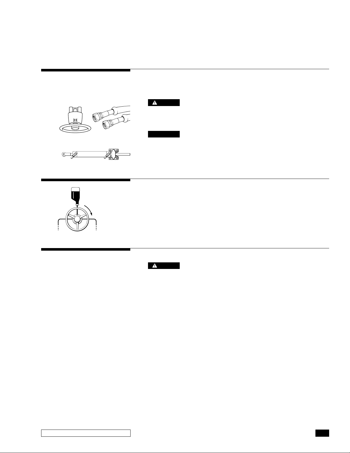
Standard Helm Mounts
Optional Helm Mounts
Additional Tools Needed
You will need the following tools to complete your installation.
• 3" (77mm) diameter Hole Saw or Key Hole Saw.
• 5⁄16" (8mm) dia. Drill.
• 7⁄16", 9⁄16", 5⁄8" and 3⁄4" Open End type Wrench/Spanner.
• 15⁄16" Socket.
• Square Bezel Backmount, HA5418, 4-1 ⁄ 2" (115 mm) Hole Saw
• Round Bezel Backmount, HA5478, 4-3⁄8" (112mm) Hole Saw
• Rear mount Helm, HH5261, 1-1/6" (27mm) drill
• Tilt Helms 4-1 ⁄2" (115mm) Hole Saw
• 20° Wedge Kit HA5419 and HA5408
20° Mount Wedge
• Key Hole or Sabre Saw
• 5⁄16" (8mm) dia. Drill
• 1 ⁄2" Wrench/Spanner, Box or Open End type
• 7⁄16" Socket and Drive
Cylinder, ATM and TM Models
• 3⁄4" Wrench/Spanner, Box or Open End type, 2 required.
CAUTION
NOTICE
Cylinder, Model HC5328-3 (125-8EM)
• 1-5⁄16" Wrench/Spanner, Open or Adjustable type.
Cylinder, Other Models
• No special tools required.
Do not remove protective caps from fittings and fitting ports until
hose or tube connections are made. Contaminants in the steering
system may cause premature wear and steering malfunctions.
Disposing of excess, left over, or used fluid. If the original oil bottle
is unavailable, dispose of the steering fluid in an environmentally
conscientious manner, adhering to local and federal environmental
regulations.
Always wear safety glasses and protective clothing when working
around hydraulic fluid and components.
Inboard & Sterndrive Powered Vessels
1

THINGS YOU NEED TO KNOW
WARNING
CAUTION
CAUTION
CAUTION
WARNING
DO NOT use SeaStar PRO helms with ANY unbalanced steering
cylinder. Use of a PRO helm with an unbalanced cylinder will lead
to a lock up of the steering wheel preventing further steering
control, resulting in collision with an obstacle causing property
damage, personal injury and/or death.
SeaStar/SeaStar PRO Steering Hoses CANNOT be cut. Cutting
these hoses will render them useless and a new hose will be
required.
BEFORE beginning with this installation, confirm that ALL
components have been acquired to complete the installation,
including; helm pump(s), hose and tube, oil, pipe sealant and any
other component required. DO NOT USE Teflon tape. ONLY use a
“liquid”, Teflon based pipe sealant (such as Loctite
Take EXTREME care not to allow any foreign material or contamination
to enter the hydraulic steering system. Contamination is the main
cause of a hydraulic system to wear and or fail. Protect ALL hose/
tube ends until ready to make final connection to fitting.
Follow the maintenance procedures outlined on page 25 of this
manual as well as ALL other manuals included with the other
components of your steering system. Following these procedures,
in the time frame noted will keep you and your passengers safe
from the dangers that are present on the water. Failure to adhere
to ALL maintenance procedures included in ALL Installation and
Owner’s Manual may result in loss of steering control. Loss of
steering control may lead to unpredictable boat behavior, leading
to a collision with an obstacle and/or ejection from the boat,
resulting in property damage personal injury and/or death.
®
542).
Before Starting
2
Study this manual and ALL other manuals provided with your SeaStar
Steering System carefully and thoroughly to familiarize yourself with
all of the components and their intended or required mounting
locations. Ensure there is adequate space available for installation
of ALL components, hydraulic lines and easy access for service. It
is good practice to mount all components first, before running hoses;
this ensures the least chance of an error in hose/tube to fitting
connections. If you must run hoses first a system of marking the
various lines must be used. ALL hose/tube ends MUST be closed
off with tape or similar material to prevent contamination. Read ALL
BOLD print text, notes, cautions and warnings; reading these now
will help prevent unexpected surprises during the installation.
These instructions have been made as complete as possible, but
as brief as practical. If you have any questions please phone
Teleflex Canada, Technical Support @ 604.248.3858
SEASTAR Hydraulics
SYSTEM INSTALLATION
OVERVIEW
STEP 1
STEP 2
HELM
CYLINDER
HOSE
System Installation
• Install your SeaStar helm pump(s) onto the dash using the
installation instructions provided with your helm pump(s).
DO NOT use a SeaStar PRO helm with an
• Install steering cylinder as per the instructions on the following
Ensure that you follow the installation instructions
• Install hose/tube as per the plumbing diagrams shown on
WARNING
unbalanced cylinder.
pages.
NOTICE
for YOUR Steering Cylinder.
page 15.
Filling and Purging Procedures
• Manual purging: Refer to page 19 of this manual for bleeding
details.
• Power Purging: Refer to Power Purge Installation Manual.
STEP 3
System Check
• The System Check shown on page 24 of this
WARNING
manual MUST be completed after installation. Doing so will
ensure the safe operation of your steering system. Any fault
(leaks or malfunction) will present itself during this check.
Failure to perform this check may result in loss of steering
control. Loss of steering control may lead to unpredictable boat
behavior, leading to a collision with an obstacle and/or ejection
from the boat, resulting in property damage personal injury
and/or death.
Inboard & Sterndrive Powered Vessels
3

CYLINDER MOUNTING
All Inboard ATM & TM/TMC Models
General
CAUTION
WARNING
CAUTION
Proper cylinder mounting is CRITICAL to the successful operation of
your hydraulic steering system. An incorrectly installed cylinder WILL
lead to rapid seal and bearing wear as well as non-repairable damage.
Select the diagram and dimensional data that corresponds with
your cylinder model. Note, not all possible cylinder mounting
configurations are shown, however, all necessary dimensions are
shown regardless of mounting configurations.
If installing rudder stops, ensure that the cylinder(s) reach hardover BEFORE rudder stops are engaged.
Where applicable, cylinders should be secured with thru bolts,
NOT with lag screws. Failure to adhere to this warning may result
separation of steering components leading to loss of steering
control, which may result in unpredictable boat behavior, leading
to a collision with an obstacle and/or ejection from the boat,
resulting in property damage personal injury and/or death.
Cylinder hose/bleeder fittings must always be installed in the
uppermost position. If this is not possible the cylinder must be
disconnected from mount to allow the bleeder fittings to be in the
up-right position, then, once all air is removed the cylinder can be
re-installed. Leaving air in the system will drastically affect
performance of your steering system.
CAUTION
Protect cylinder shafts from nicks and scratches. A damaged
cylinder shaft can not be repaired and a new cylinder will need to
be purchased.
All parts used are corrosion resistant, however with extended
operation under extremely corrosive conditions, corrosion may
occur and affected parts should be replaced.
In order to avoid excess steering loads and to optimize steering
performance, outdrive trim tabs must be adjusted in accordance
with the engine manufacturer’s instructions for specific boat/motor
combinations. Failure to do so will drastically change the
performance and handling characteristics of your boat.
4
SEASTAR Hydraulics
HYDRAULIC STEERING
INBOARD (ATM)
Inboard ATM Cylinder
Models:
HC5312-3 (BA125-7ATM)
HC5313-3 (BA135-7ATM)
HC5314-3 (BA150-7ATM)
NOTICE
NOTICE
In order to obtain a correct push
and pull angle between the tiller
arm and cylinder, or tiebar and
cylinder, the cylinder should be
parallel to the transom, tiebar or
the keel line (depending on your
mounting configuration) when
cylinder rod is fully extended (out)
or fully retracted (in).
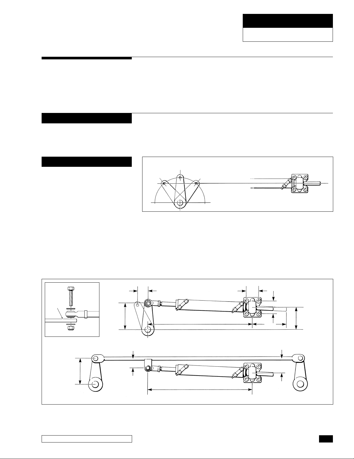
1 Minimum side loading of cylinder rod and maximum cylinder
performance of ATM and TM Models can be achieved as
illustrated below.
An imaginary line drawn through the tiller arm hole at both hard
over positions will create the cylinder centre line. With tiller arm
at hard over positions, angle X and Y should be the same.
To achieve MAXIMUM cylinder performance it is suggested that an
imaginary line is drawn though the tiller arm hole at both hard over
positions (see figure 2), this will create the “cylinder center line”.
With the tiller arm at hard over positions, angle X and Y should be
the same.
CENTER LINE FOR CYLINDER
MOUNT
Y X
TILLER ARM SHOWN IN HARD
OVER AND MIDSHIP POSITIONS
Figure 2.
2 Set rudder(s) in the fore and aft position and then attach rod
end ball joint to the tiller arm or tiebar.
3 Remove caps from cylinder hose fittings.
4 Extend cylinder rod to arrive at 20" (508 mm) from center of rod
end ball joint hole to the center of the mounting foot, (as shown
in figure 3 below).
TILLER
ARM
(152mm)
Attachment to Tiller Arm,
recommended per ABYC.
6"
(152mm)
Figure 3.
Inboard & Sterndrive Powered Vessels
6"
2" (51mm)
3-1⁄2" (89mm)
20" (508mm)
20" (508mm)
2-1⁄4"
(57mm)
2-1⁄4" (57mm)
4-3⁄4" (121mm)
8"
(203mm)
3-3⁄4"
(95mm)
5

HYDRAULIC STEERING
INBOARD (ATM)
CAUTION
NOTICE
WARNING
CAUTION
There is NO adjustment for centering cylinder after installation.
Correct mounting is critical at this time. Total cylinder travel is 7"
(178mm).
For twin rudders, the cylinder may be mounted directly to the tiebar
or to one of the tiller arms. ENSURE all measurements remain the
same as if mounting to a rudder arm.
5 Secure mounting foot to transom or mounting bracket using
four 5/16" (8mm) Grade 5 bolts (corrosion resistant) and selflocking nuts.
6 BEFORE final hose/tube connection, swing rudder(s) back and
forth to ensure free movement of cylinder and that there is no
binding of the rod end ball joint.
Any binding and or interference MUST be corrected prior to use.
Failure to do so may lead to separation of components and/or
prevention of steering control. Separation of components or loss
of steering control may lead to unpredictable boat behavior and/
or a collision with an obstacle and/or ejection from vessel
resulting in property damage, personal injury and/or death.
The cylinder ball mount allows up to 15 degrees of movement
MAX. Any movement beyond 15 degrees will result in premature
seal and/or bearing wear.
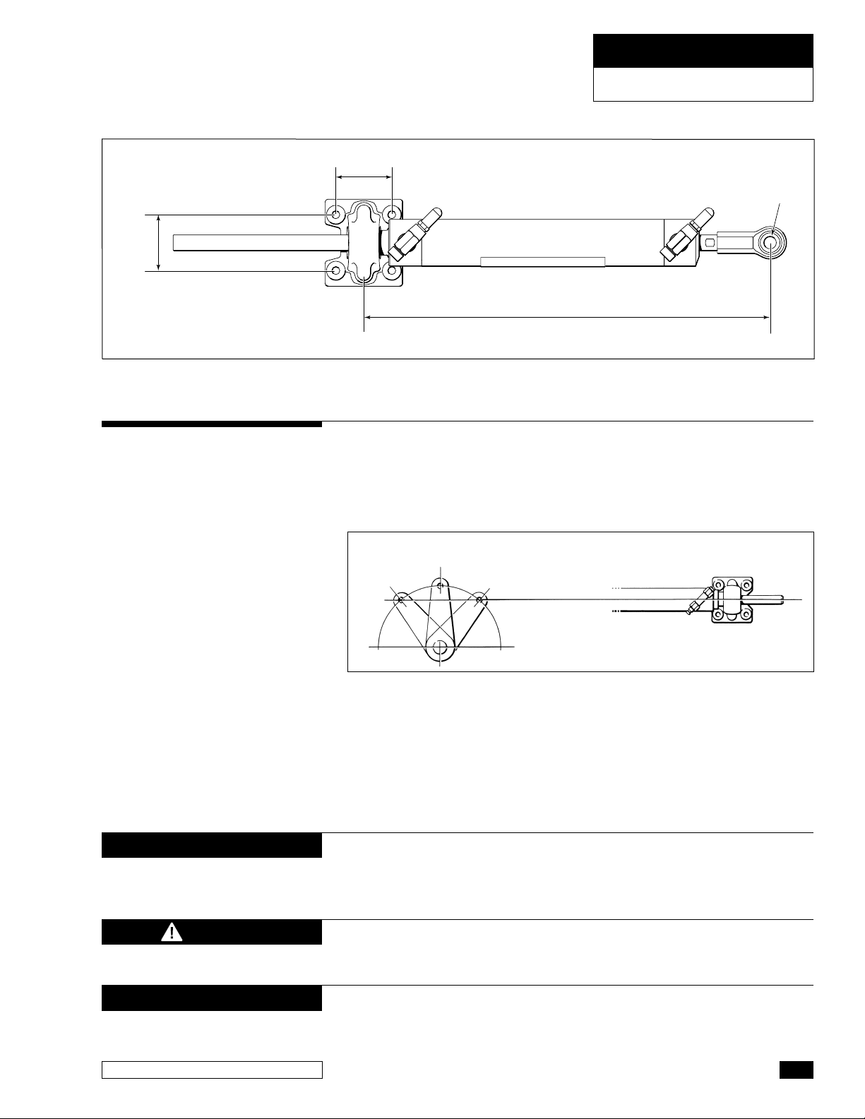
Jet Drive Cylinders:
HC1503-3 (BA150-3ATM),
HC5303-3 (BA125-3ATM)
HC6324-3 (BA150-3.5ATM)
HC1503-3 (BA150-3ATM) &
HC5303-3 (BA125-3ATM)
2-1/4"
(57mm)
Figure 4.
These cylinders are generally used in jet drive applications. ALL
warnings, cautions and notices shown on page 5 and this page are
to be followed to ensure safe operation of the steering system.
Teleflex does not make a recommendation as to the installation to
a jet drive. The measurements shown below are used to assist with
the installation.
2-1/4"
(57mm)
RETRACTED = 12-1/4" (311mm)
EXTENDED = 15-1/4" (387mm)
MID-STROKE = 13-3/4" (349mm)
1/2"
(13mm)
HOLE
6
SEASTAR Hydraulics
HYDRAULIC STEERING
INBOARD (TM & TMC)
HC6324-3 (BA150-3.5ATM)
2-1/4"
(57mm)
Figure 5.
Inboard, TM & TMC
Cylinder Models:
HC5318 (BA150-7TM)
HC5319 (BA175-7TM)
HC5369 (BA150-9TM)
HC5373 BA175-9TM)
2-1/4"
(57mm)
RETRACTED = 12.485" (317mm)
EXTENDED = 15.978" (406mm)
MID-STROKE = 14.235" (362mm)
1/2"
(13mm)
HOLE
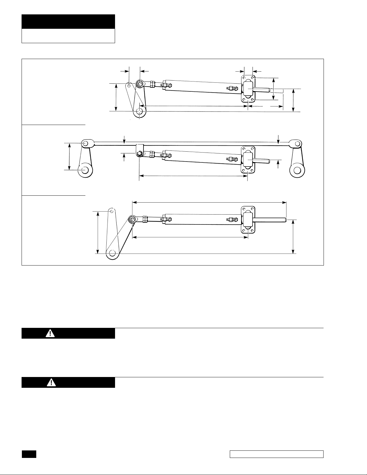
1 To achieve MAXIMUM cylinder performance it is suggested that
an imaginary line is drawn though the tiller arm hole at both hard
over positions (see figure 6), this will create the “cylinder center
line”. With the tiller arm at hard over positions, angle X and Y
should be the same.
CENTER LINE FOR CYLINDER
MOUNT
Y X
NOTICE
CAUTION
NOTICE
TILLER ARM SHOWN IN HARD
OVER AND MIDSHIP POSITIONS
Figure 6.
2 Set rudder(s) in the fore and aft position and then attach rod
end ball joint to the tiller arm or tiebar.
3 Remove caps from cylinder hose fittings.
4 Extend cylinder rod to arrive at 21" (533 mm) or 23-1/4" (591 mm)
from center of rod end ball joint hole to the center of the mounting
foot. See figure 7.
In order to obtain a correct push and pull angle between the tiller arm
and cylinder, or tiebar and cylinder, the cylinder should be parallel
to the transom, tiebar or the keel line (depending on your mounting
configuration) when cylinder rod is fully extended (out) or fully retracted (in).
There is NO adjustment for centering cylinder after installation.
Correct mounting is critical at this time. Total cylinder travel is
7" or 9" (depending on your cylinder model)
For twin rudders, the cylinder may be mounted directly to the tiebar
or to one of the tiller arms. ENSURE all measurements remain the
same as if mounting to a rudder arm.
Inboard & Sterndrive Powered Vessels
7
HYDRAULIC STEERING
INBOARD (TM & TMC)
HC5318 (BA150-7TM)
HC5319 (BA175-7TM)
6"
(152mm)
HC5369 (BA150-9TM)
HC5373 (BA175-9TM)
(228mm)
(152mm)
9"
6"
3" (76mm)
3-1⁄2" (89mm)
23-1⁄4" (590mm)
21" (533mm)
21" (533mm)
29" (736mm)
1-9⁄16" (40mm)
4" (102mm)
8"
(203mm)
4-1⁄4"
(108mm)
4-3⁄4"
(121mm)
7-3⁄4"
(197mm)
Figure 7.
WARNING
CAUTION
5 Secure mounting foot to transom or mounting bracket using
four 3/8” (10mm) Grade 5 bolts (corrosion resistant) and selflocking nuts.
6 BEFORE final hose/tube connection, swing rudder(s) back and
forth to ensure free movement of cylinder and that there is no
binding of the rod end ball joint.
Any binding and or interference MUST be corrected prior to use.
Failure to do so may lead to separation of components and/or
prevention of steering control. Separation of components or loss
of steering control may lead to a collision with an obstacle and/
or ejection from vessel resulting in property damage, personal
injury and/or death.
The cylinder ball mount allows up to 15° of movement MAX. Any
movement beyond 15° will result in premature seal and/or bearing wear.
8
SEASTAR Hydraulics
HYDRAULIC STEERING
STERNDRIVE
Sterndrive Engine Mount Cylinders
General
WARNING
NOTICE
DO NOT use SeaStar PRO helm(s) with an unbalanced cylinder.
Using a PRO helm with an unbalanced cylinder WILL lead to steering
wheel “lock-up”. Lock-up may lead to collision with an obstacle
resulting in property damage, personal injury and/or death.
Sterndrive cylinders are designed for use, in conjunction with, the engine
manufacturer’s power steering system. DO NOT Install into an application
that does not use the engine manufacturers power steering.
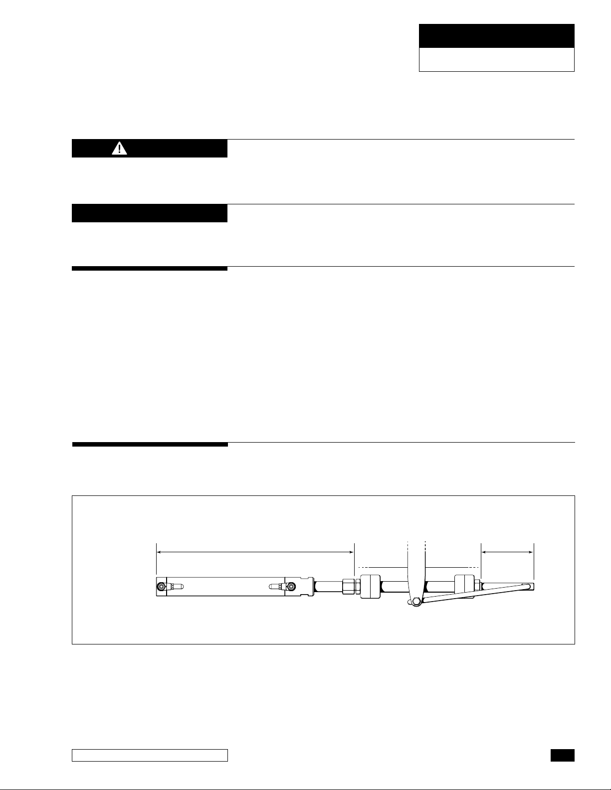
1 A support tube and/or cable support tube provided by the engine
manufacturer MUST be used for these three steering cylinders.
These cylinders are mounted to the sterndrives support/tube
guide support in the same manor as a steering cable.
2 Thoroughly lubricate support tube/cable guide tube, and cylinder
rod with a high quality, anti-corrosive type marine grease (such
as OMC Triple Guard or equivalent) BEFORE mounting cylinder to
support tube.
3 Slide well greased cylinder rod into and through well greased
support/cable guide tube and thread cylinder fully onto support
tube as shown below.
HC5328-3 (125-8EM)
HC5329-3 (128-8VEM)
HC5328-3
(125-8EM)
HC5329-3
(128-8VEM)
Figure 8. HC5328-3 (125-8EM) and HC5329-3 (128-8VEM), NOT for use with SeaStar PRO helm(s).
HC5328-3 = 17-1⁄4" (438mm) MAX.
HC5329-3 = 21-5⁄8" (549mm) MAX.
9" (228mm)
Inboard & Sterndrive Powered Vessels
9
HYDRAULIC STEERING
STERNDRIVE
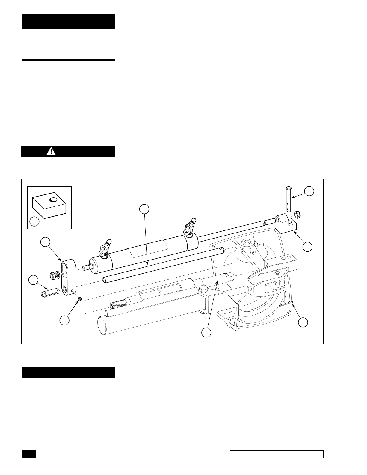
HC5331-3 (92VPS)
CAUTION
9
Referring to Figure 9 please observe the following:
• Rotate Cable Tube item 1 into threads of Item 2 until tight.
• Torque setscrew (item 7) to 90 in-lbs and tube insert (item 8)
until tight.
• Item 3 must pass through items 4 and 5 before being secured
by Item 6.
• Always mount cylinder in lower mount position of item 2 and
without spacer item 9, unless mechanical interference prevents
you from doing so.
Cut Clevis Pin, (item 3 Figure 9) to a length of 2" when mounting
cylinder in lower position.
3
5
2
8
7
Figure 9. HC5331-3 (92-VPS), NOT for use with SeaStar PRO helm(s).
NOTICE
The Teleflex HC5331-3 steering cylinder is NOT compatible with some
early model power steering rams. Although the cylinder will still mount
to these rams, loss of articulation and possible damage to the steering
ram may result. Please identify your power steering cylinder by
comparing your clevis bracket to the 4 drawings shown below. The
HC5331-3 IS compatible with units identified by figures 10 to 12,
NOT compatible with the clevis bracket shown in figure 13.
4
6
1
it is
10
SEASTAR Hydraulics
 Loading...