

Teleflex Marine 311482-002 User Manual

TELEFLEX MORSE Marine Products
Marine Ignition
Interrupt Switch
Part Numbers
311482-001 (For I/0s and Inboards)
311482-002 (For Outboards)
For Use With Teleflex Morse MV3 Side Mounted Controls
Installation Manual
This manual must be accessible to the owner/user of this
Teleflex Morse Marine Product
PLEASE READ THESE INSTRUCTIONS CAREFULL Y
AND THOROUGHLY BEFORE INSTALLING OR OPERATING
THIS IGNITION INTERRUPT SYSTEM! YOU MUST HAVE
THE MV3 SIDE MOUNTED CONTROL INSTRUCTIONS AND
MOUNTING TEMPLA TE WITH YOU T O PROPERLY INSTALL
THIS MARINE PRODUCT.
All specifications and features are subject to change without notice.
INST ALLA TION, OPERATION and
MAINTENANCE INSTRUCTIONS
Page 1 of 4 Pages
055001-695 Rev. C 10/03 © 2003 Teleflex, Inc.
ë\
General Information
This Interrupt Switch is to be used solely with
Morse MV3 Side Mounted Controls to stop the
engine of an inboard, I/O or outboard powered
boat instantly in the event an operator is accidentally removed from the controls. The Interrupt
Switch includes a lanyard clip which holds the
plunger of the Switch in position to allow engine
operation. A lanyard extends from the clip and is
connected to the operator. Should the operator
move away from the controls the clip is pulled
free, releasing the plunger and stopping the
engine.
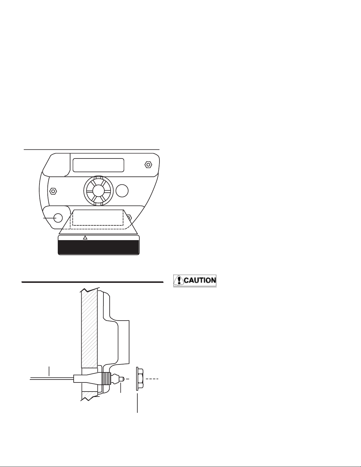
F i g u r e 1 .
5 / 8 "
D i a m e t e r
S w i t c h
M o u n t i n g
H o l e
F i g u r e 2 .
o p e r a t o r w h i l e e n g i n e i s r u n n i n g . Q u a l i f i e d
o p e r a t o r m u s t b e i n c o n t r o l a t a l l t i m e s .
!
I n t e r r u p t s w i t c h m u s t b e a t t a c h e d t o
R e a d O w n e r ' s M a n u a l b e f o r e u s e .
W A R N I N G
Installation
1. Before drilling, check behind the panel for
sufficient clearance around wires, pipes,
control cables and other obstructions.
2. Remove control and drill a 5/8 inch diam
eter hole in the cover from the backside. A
drill point is molded in.
2A. You may use the 5/8 inch diameter hole that
you drilled in the control cover as a pilot hole
and drill a 1-1/8 inch hole in the mounting
panel.
2B. Add the ìWARNINGî label to the bottom
of the MV3 Face Plate. (See Figure 1.)
3. Insert the Interrupt Switch from behind the
mounting surface, through the MV3
Control.
4. Tighten the Flanged Nut to 40-50 inch
pounds to secure the Switch. Do not over
tighten.
5. Check for proper mounting security by
removing the lanyard assembly with a tug
on the cord. Re-tighten nut if the Switch is
loose.
Electrical Connections for I/O or Inboard Use
Only
1. Disconnect all batteries and any auxiliary
on-board or dockside power supplies.
2. Locate the purple ignition switch-to-coil wire.
See Diagram A.
B e S u r e M o u n t i n g A r e a
i s S o u n d a n d S e c u r e .
M o u n t i n g
P a n e l
T e r m i n a l s
BE SURE THIS WIRE GOES DIRECTLY TO
THE COIL AND NOT TO THE INSTRUMENT OR ALTERNAT OR CIRCUIT.
SELECTING THE INCORRECT WIRE WILL
RESUL T IN IMPROPER SWITCH OPERATION WHICH COULD LEAD TO SERIOUS
lNJURY.
3. Cut the Purple wire, strip the ends and
install two (2) insulated crimp-on 1/4 inch
female disconnect terminals. A crimping tool
designed for insulated terminals MUST be
used.
P l u n g e r
4. Attach the female disconnects to each of
the male terminals on the Interrupt Switch.
5. Recheck all connections. Install Lanyard
F l a n g e d N u t .
T i g h t e n 4 0 - 5 0
055001-695 Rev. C 10/03 © 2003 Teleflex, Inc.
with the Fork Clip seated on the Plunger.
Page 2 of 4 Pages
 Loading...