

Page 1
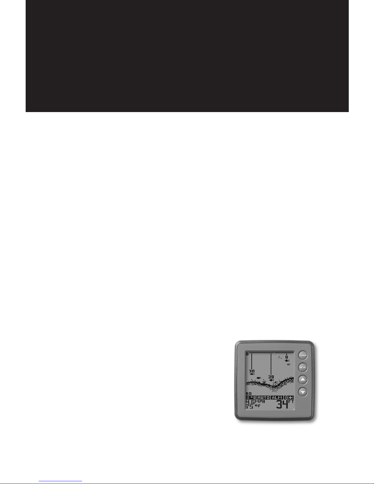
TFX100ID
Operations Manual
Page 2

Thank you for choosing Teleflex Sonar, manufactured by Techsonic Industries,
for your sonar fishfinder and depthsounder. Techsonic has built its reputation
by designing and manufacturing top-quality, thoroughly reliable marine equip-
ment. Techsonic has designed your Teleflex Sonar unit to be trouble free even
in the harshest marine environments.
In the unlikely event that your Teleflex Sonar product does require repairs,
Techsonic offers an exclusive Service Guarantee - free of charge during the first
year after purchase, and available at a reasonable rate after the one-year
period. Complete details are included at the end of this manual.
We encourage you to read this operations manual carefully in order to get full
benefit from all the features and uses of your Teleflex Sonar product. Also, to
register your purchase and help us learn more about you, please fill out the
included warranty registration card
WARNING! This device should not be used as a navigational aid to
prevent collision, grounding, boat damage, or personal injury. When
the boat is moving, water depth may change too quickly to allow
time for you to react. Always operate the boat at very slow speeds if
you suspect shallow water or submerged objects.
THANK YOU
WARNING:
Dis-assembly and repair of this electronic unit should only be performed by authorized service
personnel. Any modification of the serial number or attempt to repair the original equipment or accessories by
unauthorized individuals will void the warranty. Handling and/or opening this unit may result in exposure to
lead, in the form of solder.
WARNING: This product contains lead, a chemical known to the State of California to cause
cancer and birth defects and other reproductive harm.
Page 3

TABLE OF CONTENTS
Section One: USING the 100ID Series . . . . . . . . . . . . . . . . . . . . . . . . . .2
How Sonar works . . . . . . . . . . . . . . . . . . . . . . . . . . . . . . . . . . . . . . . . . . . .2
Introduction . . . . . . . . . . . . . . . . . . . . . . . . . . . . . . . . . . . . . . . . . . . . . . . .3
Simulator Operation . . . . . . . . . . . . . . . . . . . . . . . . . . . . . . . . . . . . . . . . . .3
Using Depth Offset . . . . . . . . . . . . . . . . . . . . . . . . . . . . . . . . . . . . . . . . . . .3
What You See On-Screen . . . . . . . . . . . . . . . . . . . . . . . . . . . . . . . . . . . . . .5
Control Functions . . . . . . . . . . . . . . . . . . . . . . . . . . . . . . . . . . . . . . . . . . . .8
Menu Functions . . . . . . . . . . . . . . . . . . . . . . . . . . . . . . . . . . . . . . . . . . . . .9
Section Two: Maintenance and Warranty . . . . . . . . . . . . . . . . . . . . .18
Maintenance . . . . . . . . . . . . . . . . . . . . . . . . . . . . . . . . . . . . . . . . . . . . . .18
Troubleshooting . . . . . . . . . . . . . . . . . . . . . . . . . . . . . . . . . . . . . . . . . .19
One Year Warranty . . . . . . . . . . . . . . . . . . . . . . . . . . . . . . . . . . . . . . . . .20
Service Policy . . . . . . . . . . . . . . . . . . . . . . . . . . . . . . . . . . . . . . . . . . . . . .21
Customer Support . . . . . . . . . . . . . . . . . . . . . . . . . . . . . . . . . . . . . . . . . .22
Specifications . . . . . . . . . . . . . . . . . . . . . . . . . . . . . . . . . . . . . . . . . . . . . .23
Rev 10420E
Page 4
2
USING THE 100ID SERIES
HOW SONAR WORKS
HOW SONAR WORKS
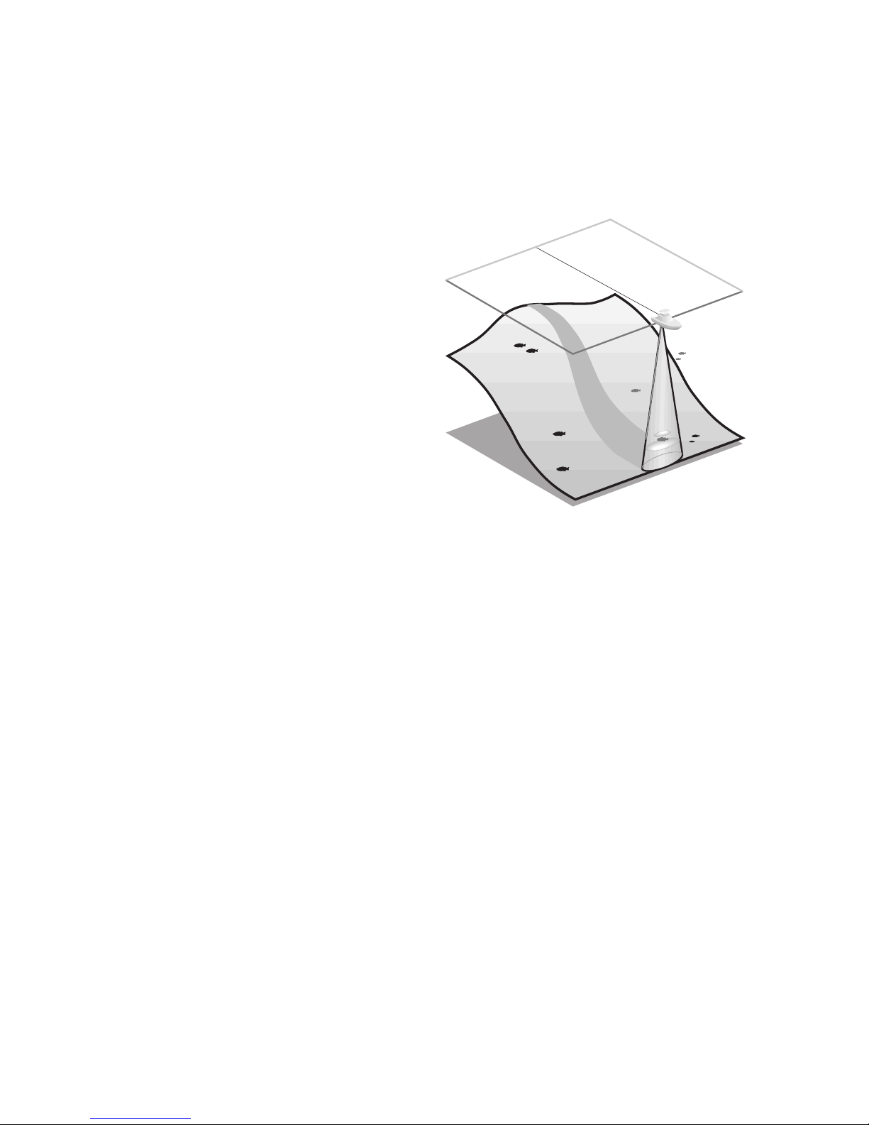
Your Teleflex Sonar unit uses sonar
to locate and define underwater
objects, define the bottom terrain, as
well as determine distance.
Sonar technology is based on sound
waves. Your sonar unit sends out a
sound wave signal. With this signal it
determines distance by measuring
the time between the transmission
of the sound wave and when the
sound wave is reflected off an
object. Your sonar uses the reflected
signal to interpret location, size and
composition of an object.
Sonar is very fast. A sound wave can travel from the surface to a depth of
600' (185m) and back again in less than
¹⁄₄ of a second. It is unlikely that
your boat can "outrun" this sonar signal.
The
100ID series is a single frequency, single beam unit, and generates a 16°
symmetrical cone of sonar coverage at 200kHz. The 16° coverage shows
excellent bottom detail with a greater depth capability than wider beams.
The sonar return shows the most current information at the right of the
screen and draws a history of the information as it scrolls across to the left.
Actual depth capability depends on factors such as bottom hardness,
water conditions, and transducer installation. Units will typically read to
deeper depths in fresh water than in salt water.
Page 5
3
INTRODUCTION
The 100ID series is easy to use. Simply press the POWER button, and the
unit will automatically locate the bottom, adjust the depth range and
sensitivity to an appropriate level, and draw a picture of the terrain
beneath your boat. If
POWER is the only button you press, you will benefit from the advanced automatic bottom tracking capability of the unit.
However, if you choose to experiment with the many features and
controls the
100ID offers, you can customize the presentation of informa-
tion to suit your particular needs. The
100ID offers a wide variety of
settings and types of display, to satisfy any sonar need.
SIMULATOR OPERATION
The 100ID contains a simulator which allows you to use the unit as if you
were on the water. This simulator is invaluable for learning how to operate the many features of the
100ID unit.
With the unit turned off, press and hold
POWER until you hear a continu-
ous chirp. This initiates the simulator operation. Your
100ID will simulate
all functions as if it were actually on the water.
To exit the simulator, press
POWER to turn the unit off. Pressing POWER
again will power-up the unit for normal operation.
When in simulator operation, the
100ID unit will respond to control
inputs as if it were in actual operation, so feel free to experiment with
the many features and functions to
customize the
100ID unit for your
particular application.
USING DEPTH OFFSET
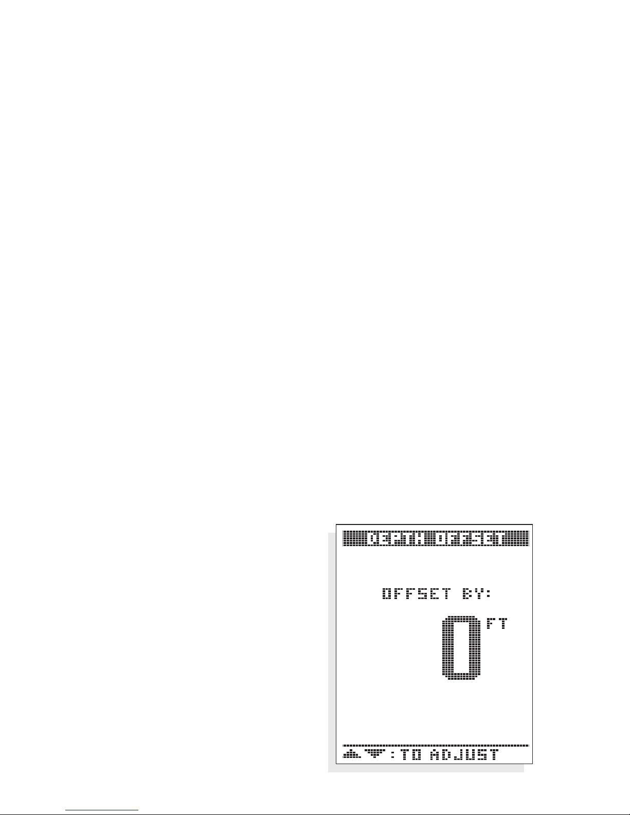
Depth Offset adjusts the digital
depth readout to show distances
approximated from either the waterline, or the lowest point of the hull.
This is accomplished by selecting an
USING THE 100ID SERIES
INTRODUCTION
Depth Offset at Zero
Page 6
USING THE 100ID SERIES
USING DEPTH OFFSET
offset value at start up which the unit
adds or subtracts to the sonar depth
measured from the location of the
transducer.
When you turn on the
100ID, the
Depth Offset screen will appear for
several seconds to allow time to select
your depth offset. Use the UP or
DOWN arrows to adjust the setting to
yield the desired depth measurement
as follows.
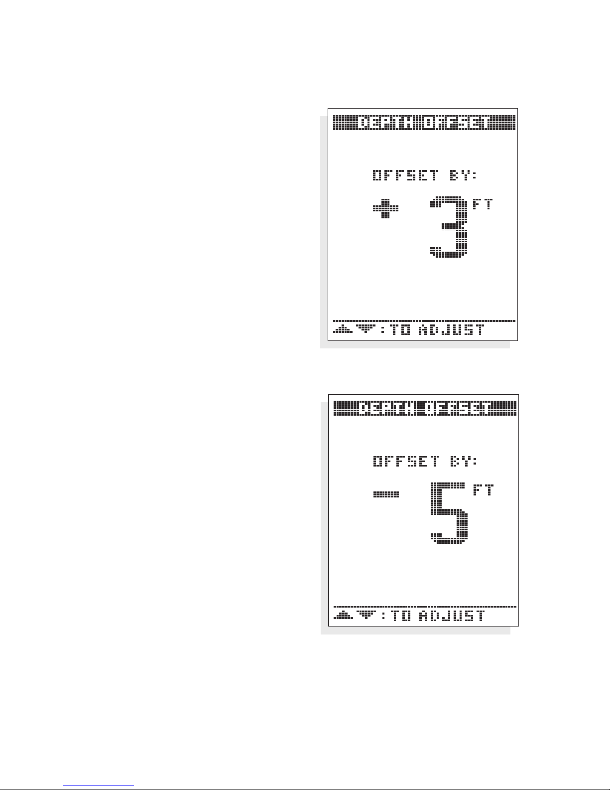
Selecting a positive number equal to
the vertical distance between the transducer and waterline provides a depth
reading approximated from the waterline. This “true depth” is useful for
comparing to depth soundings plotted
on navigation charts. Use caution when
operating in suspected shallow water
as many factors such as tide and waves
can effect the actual depth.
Selecting a negative number equal to
the vertical distance between the
transducer and lowest point of the hull
will give depth readouts from the
bottom of the hull, or keel.
Leaving the depth offset at zero will
have no effect on the depth readout as
measured from the transducer.
Depth Offset has a range of adjustment of -10 to +10 feet, and must be
set at start-up each time the unit is powered on.
Depth Offset to Waterline
Depth Offset to Keel
4
Page 7
5
USING THE 100ID SERIES
WHAT YOU SEE ON-SCREEN
WHAT YOU SEE ON-SCREEN
The first thing you may notice about the 100ID unit is the high-resolution
LCD display. The LCD display uses super-twist technology, for maximum
viewability and is ruggedized for tough shock and vibration endurance.
The display can operate at temperatures more extreme than you are likely
to encounter.
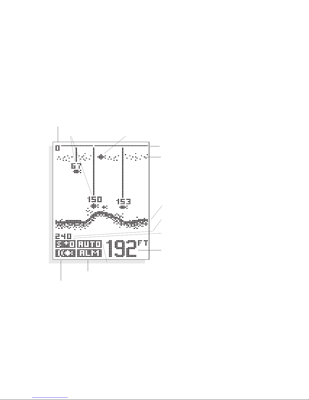
There are two basic screen layouts for the
100ID. Figure A shows the
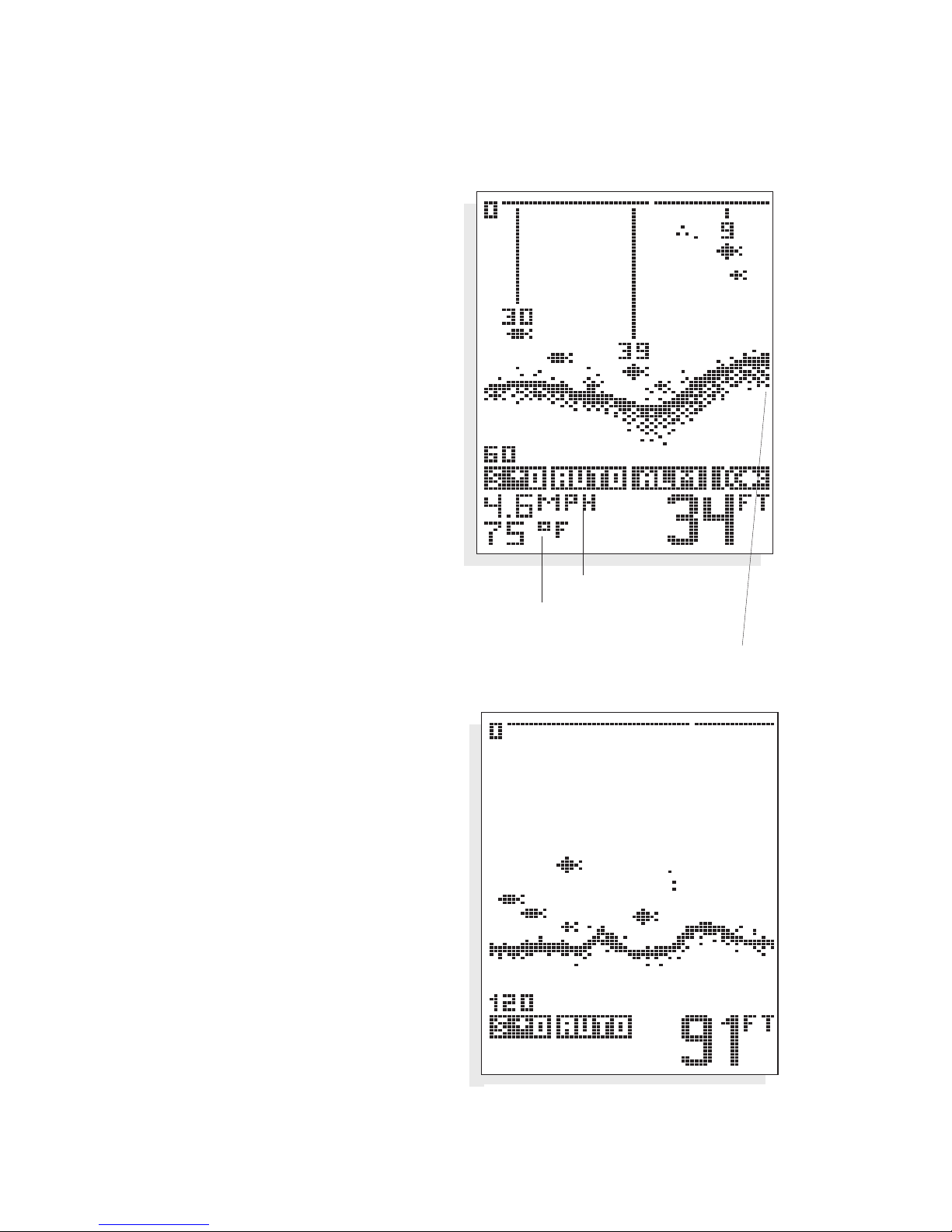
default screen layout which does not include speed and temperature readings. If you have purchased the
Speed and Temperature accessory and it is
installed, the screen layout will be slightly different as shown in Figure B.
The number of vertical pixels (picture elements or dots) in a given depth
range determines the display resolution, or ability to differentiate targets
close to the bottom or other targets. The
100ID is capable of distinguish-
ing between targets only 6" apart, and show fish within 6" of the bottom.
Figure A
Zero Line
Thermocline
Bottom Terrain
Lower Range Limit
Sensitivity Setting
Depth
Range Control Setting
Bottom Alarm Indicator
Fish Alarm Indicator
Upper Range Limit
ID+ Fish Depth Fish Symbol
Page 8
6
On all screens the horizontal
line at the top of the display is
the “Zero” line. This represents the surface of the water.
The “Zero” line will always
have a gap which moves as
the screen updates. This gap
lets you know that the display
is updating even if the bottom
terrain remains the same or is
not visible on the selected
depth range. The farthest
right column of information is
the most recent information,
and it shows what is directly
under your boat.
At power-up, the
100ID
locates the bottom and
adjusts the depth range to a
setting most appropriate for that
depth. The bottom will be usually
shown about
²⁄₃ of the way down
the display. The Structure ID™
depiction of the bottom will vary in
appearance depending on the
bottom terrain. If the bottom is
very hard and smooth, the bottom
depiction will be narrow and
dense. If the bottom is mud or soft
sand, the bottom depiction will be
thick and less dense. This indicates
that much of the sonar signal is
absorbed by the soft bottom. If the
bottom is rugged and varying, such
as a rocky bottom, the depiction
will be textured and vary in density.
Structure, such as submerged trees
or brush, or other objects are
clearly displayed above the solid bottom return, in varying densities of
USING THE 100ID SERIES
WHAT YOU SEE ON-SCREEN
Figure B
Boat Speed
Water Temperature
Most current information
Hard Smooth Bottom
Page 9
7
pixelization. This bottom depiction is
useful in locating structure, by comparing
relative density as well as depth.
The transmitted sonar signal travels downward, and is reflected back toward the
surface by the bottom or other objects for
display on-screen. The signal does not stop
there - it is reflected downward again by the
surface of the water, and a weak “second
return” is usually visible if the depth range is
sufficient to see it. A second return is shown
in the figure below. Some users use this
second return as an indicator when setting
the sensitivity bias.
If a target is detected between the surface
and the bottom, it is displayed as a fish
symbol. Depending on the strength of the
signal reflected from the object, one of
three different size symbols is used. These
reflected signals are “normalized” for depth,
so that a small fish does not appear to be a
large fish if it is close to the boat.
Since some species of fish tend to be better
reflectors of sonar than others, the strength
of return is not always an accurate indicator of
fish size, however, typically the larger the
fish, the larger the signal return.
USING THE 100ID SERIES
WHAT YOU SEE ON-SCREEN
Soft Mud
Rocky Bottom
Second Return
Page 10
8
CONTROL FUNCTIONS
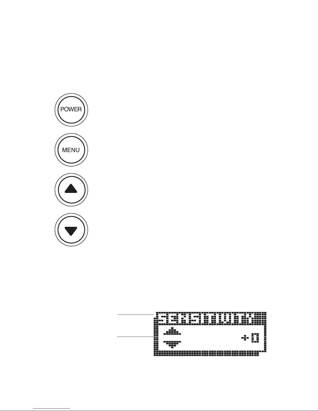
The 100ID unit uses only four buttons to control all functions. When any
button is pressed, an audible “chirp” will verify the control input.
POWER, as previously discussed, powers the 100ID for
normal operation. Also, if the unit is powered off, press and
hold
POWER until you hear a continuous “chirp” to enable
simulator operation as discussed in “Simulator Operation.”
Pressing
POWER when the unit is in normal or simulator
operation will power the unit off.
MENU brings a menu on-screen for adjustment, or if a menu
is already present, the next menu in sequence will appear.
Menus will go off-screen and normal operation will resume
after a short period of time.
UP arrow selects the next larger or next sequential adjustment within the menu. Holding an Arrow button down will
cause the unit to continue to make the adjustment, until a
limit is reached, and the limit alarm sounds.
DOWN arrow selects the next smaller adjustment within
the menu.
All menus use the same general layout as shown in the sample menu. The
heading of the menu is at the top. The area at the bottom is controlled by
the
UP and DOWN arrows.
USING THE 100ID SERIES
CONTROL FUNCTIONS
Menu Heading
Arrow Key
Functions
Page 11
9
MENU FUNCTIONS
The following section explains each menu in
detail, and how these adjustments can be
used to obtain the maximum information
from the sonar returns.
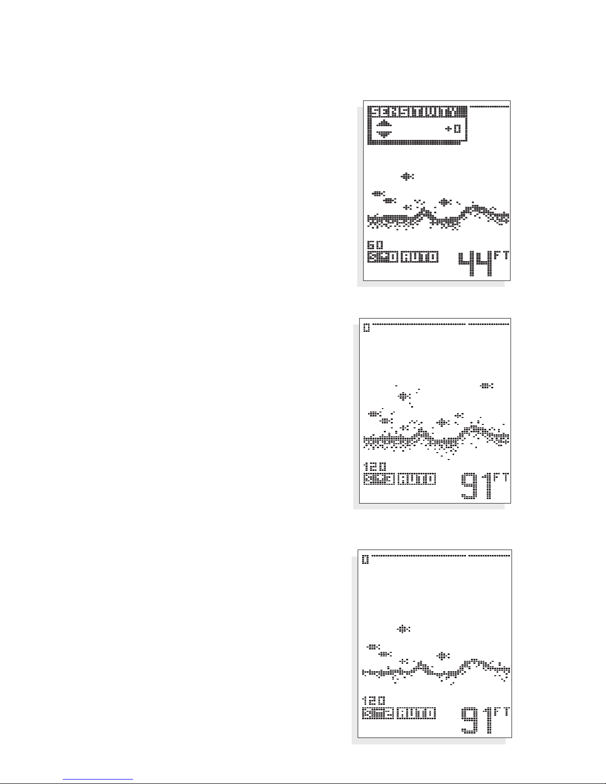
SENSITIVITY. As the 100ID receives returned
signals, the sensitivity of the receiver is
adjusted automatically based on a number of
factors such as the depth of the water, and
the signal clarity. In murky water, full of
debris, the
100ID will select a lower sensitivity
setting. In clear water, where there is little
debris to reflect the sonar signal, the sensitivity
is set higher.
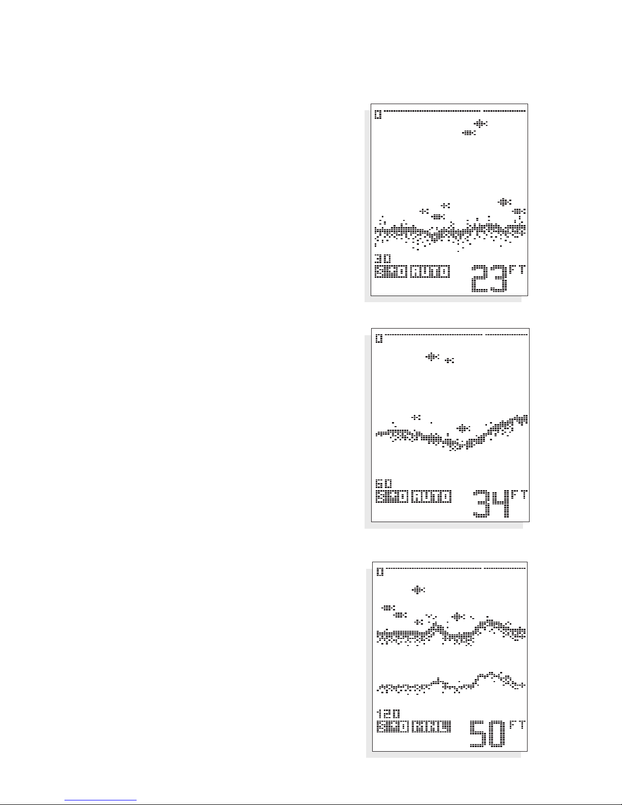
The Sensitivity menu allows you to “bias” this
automatic setting up or down based on
personal preference.
You can select a bias of +5 to -5, for 11 different bias settings. A bias setting of “0” has no
effect on the automatic function. A +3 setting
selects a sensitivity setting three steps higher
than the unit would normally select, so even
the smallest returns are displayed on-screen.
A setting of -2 sets the sensitivity two steps
below what the unit would normally select,
so only the largest targets or other returns
are displayed.
USING THE 100ID SERIES
MENU FUNCTIONS
Sensitivity bias of -2
Sensitivity bias of +3
Page 12
10
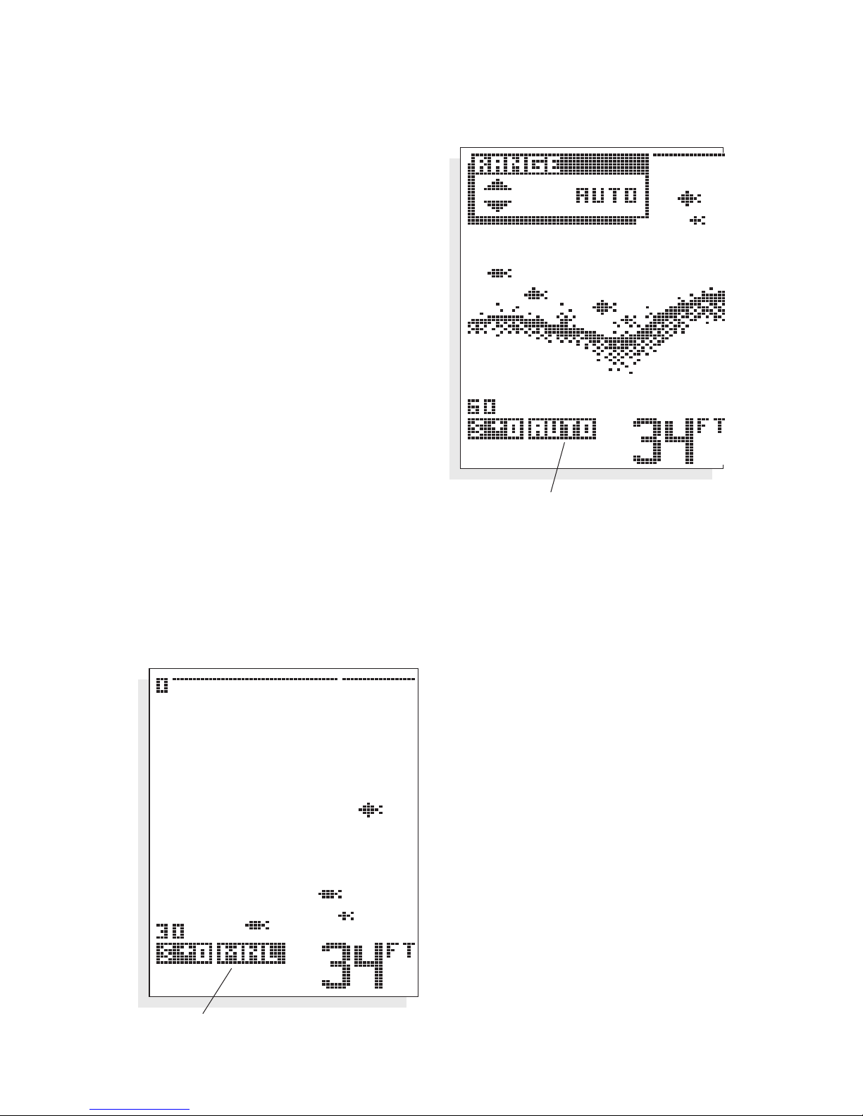
RANGE. 100ID adjusts the depth
range automatically, so the bottom
return is displayed at the bottom
¹⁄₃ of
the display. This leaves the top
²⁄₃ to
display anything between the surface
and the bottom. As your boat moves
over deeper or shallower water, the
unit adjusts the depth range of the
display to keep the bottom return in
the same general area on the screen.
However, you may choose to control
this range adjustment manually. By
pressing the
UP and DOWN arrow
buttons you can select manual operation, meaning the unit will no longer
adjust the depth range automatically.
The depth range selected is also
controlled by the
UP and DOWN arrow buttons. Ranges of 0 - 15,
30, 60, 120, 180, 240, 360, 480, and 600 feet can be selected. An
on-screen icon indicates whether the unit is in “AUTO” (automatic)
or “MNL” (manual) range control.
If you alter the depth range,
Manual operation is automatically selected. This
feature is valuable if you are
only interested in targets
near the surface. The
100ID
will always display the digital
depth of the water, regardless of whether the bottom
is shown on the selected
depth range.
USING THE 100ID SERIES
MENU FUNCTIONS
Auto Range Control Indicator
Manual Range Control
Page 13
11
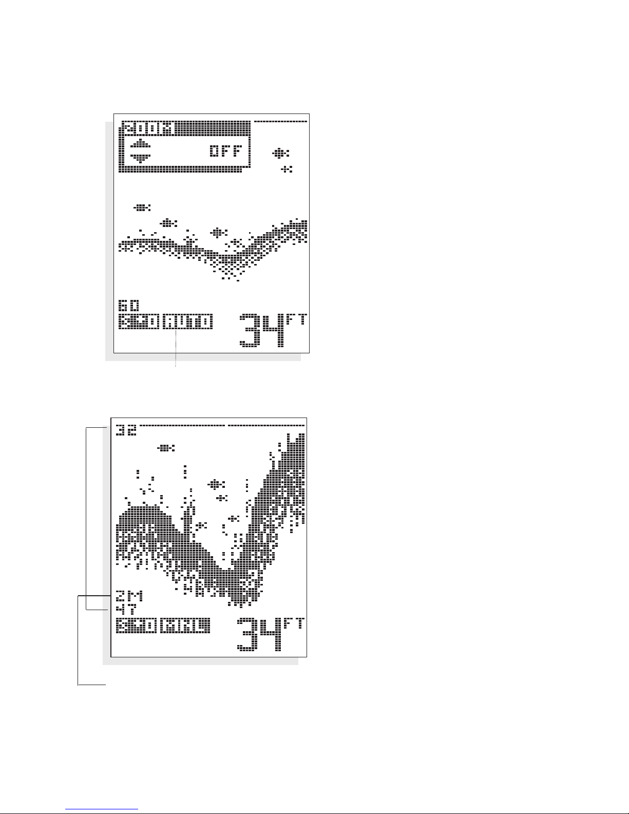
ZOOM. Another form of range
control is Zoom. Zoom allows
selection of various ranges for full
screen viewing. By using the
display to view a smaller area, the
effective display resolution is
increased, and the units ability to
separate targets close together is
enhanced.
The zoom range is determined by
the depth range in use when
Zoom is enabled. In shallow water,
when the 15' or 30' depth range is
used, the zoom range will be 15'.
If the 60' or 120' depth range is in
use, the zoom range will be 15', if
a 180' to 480' depth range is used,
the zoom range will be 30', and if
the 600' range is in use, the zoom
range will be 60'.
Pressing the
UP or DOWN arrow
button enables zoom and adjusts
the zoom ‘window’ to the desired
depth. The upper and lower limits
are shown on-screen and the digital depth readout will continue to
track the bottom even when
Zoom is enabled.
To disable Zoom press the UP
arrow button until Zoom turns off.
USING THE 100ID SERIES
MENU FUNCTIONS
Zoom Window Indicator With
current top and bottom ranges
Depth Range
Auto Range Indicator
Page 14
12
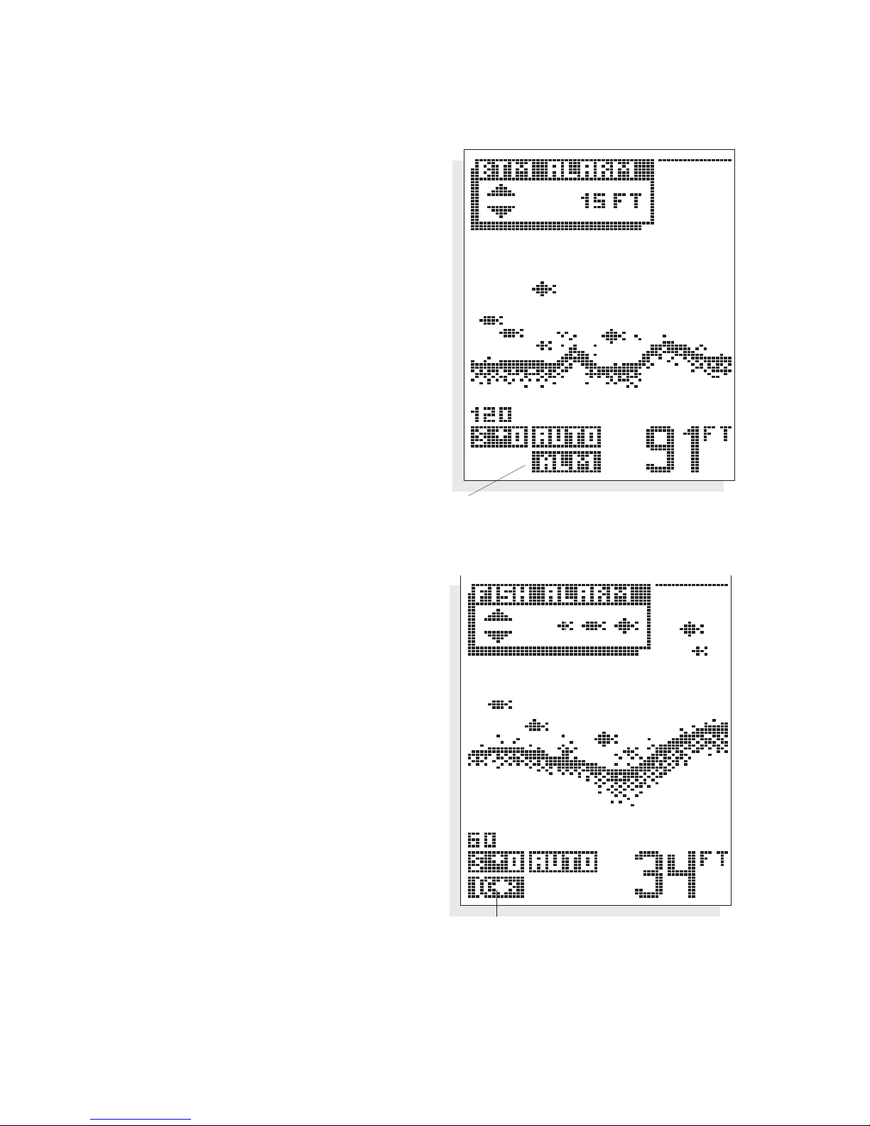
BOTTOM ALARM. The 100ID contains
an audible alarm to warn you of shallow water depths. This alarm is
adjustable from 2' to 99' of depth.
To enable the alarm, simply adjust
the alarm depth using the UP and
DOWN arrow buttons. When the
depth of the water beneath your
boat is equal to or less than the
selected alarm depth, a continuous
alarm will sound.
To disable the alarm, either move to
deeper water, or use the UP button
to turn the alarm off.
FISH ALARM. The Fish Alarm alerts
you to the presence of fish, or other
targets not attached to the bottom,
in the water beneath your boat. The
Fish Alarm has 3 different settings
which correspond to the 3 different
size fish targets shown on-screen.
To enable Fish Alarm, use the
UP
and DOWN arrow buttons to adjust
the size return you want to be
alerted to: large fish only, large and
medium size fish, or all fish. To
disable the alarm use the UP button
to return to the off position.
USING THE 100ID SERIES
MENU FUNCTIONS
Bottom Alarm “ON” Indicator
Fish Alarm “On” Indicator
Page 15
13
Remember that it is impossible for sonar to determine if a signal return is a
fish or some other type of object or suspended debris. Any object not
connected to the bottom is normally a fish and is portrayed as a fish symbol.
The strength of the reflected sonar signal from a target is a good indicator
of the size of the target, and the fish symbol displayed represents the
strength of the signal reflected from it.
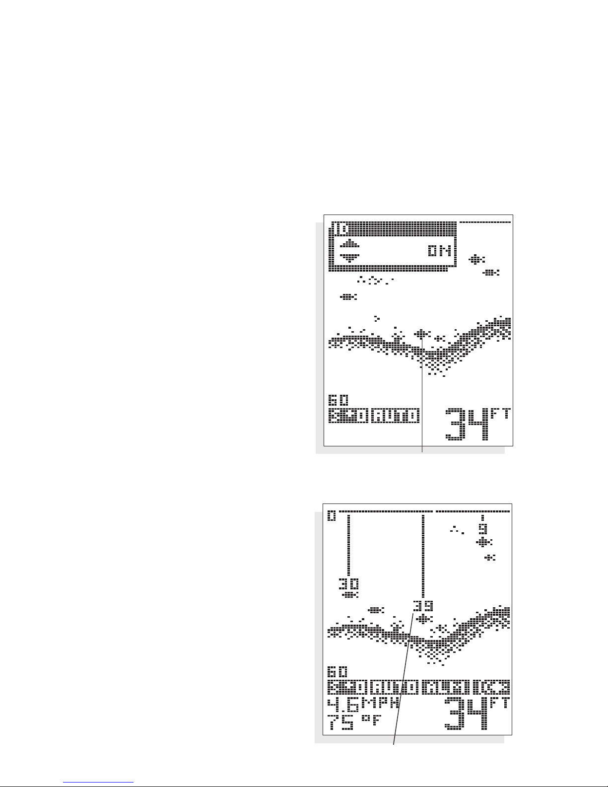
ID. ID is the automatic identification of
target returns based on the strength of
the returned signal and other factors.
Three options are available: ID “On”
displays targets as one of three different size fish symbols.
“ID+”, the default setting, provides
more information about the location
of the target by attaching depth
“strings” showing the digital depth of
the target. When there are numerous
targets on-screen, not every target
depth is shown, to avoid excessive
clutter on-screen.
USING THE 100ID SERIES
MENU FUNCTIONS
ID+ Fish Depth
ID “ON”
Page 16
14
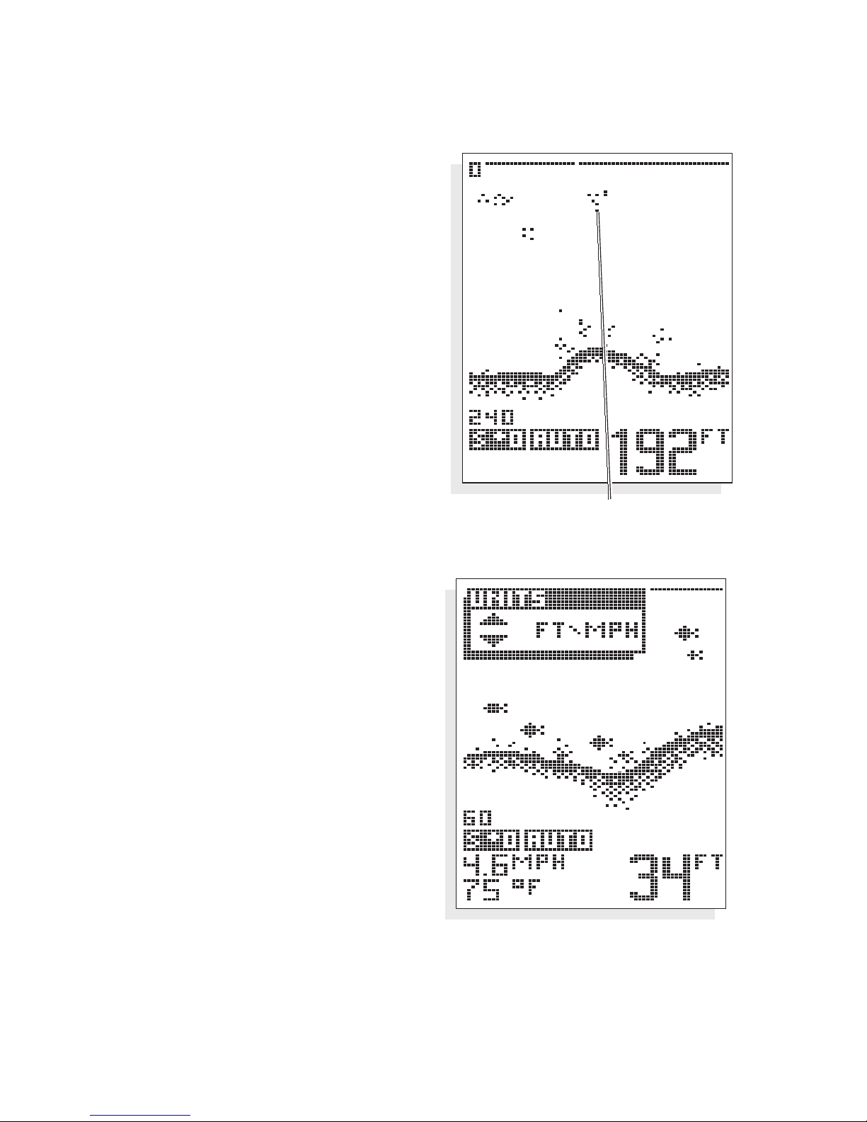
ID “Off” disables the units interpretation of targets, and displays the “raw”
sonar information as it is received.
Advanced users may prefer this type of
presentation, so they can make there
own interpretation from the information displayed.
UNITS. The Units menu is used to
select the units of measure for the
digital speed readout. Two units of
measure are available: miles per hour
(MPH) or nautical miles per hour (KTS).
The selected unit of measure also
affects the distance readout in the
Triplog menu. When MPH is selected
distance readouts will be statute miles
(MI); when KTS is selected the readouts will be in nautical miles (NM).
Note: The optional Speed &
Temperature accessory must be
connected for the Units menu to
be available.
USING THE 100ID SERIES
MENU FUNCTIONS
ID “OFF”: Raw Sonar
Page 17
15
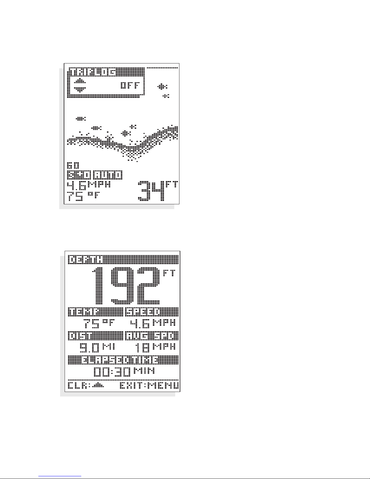
TRIPLOG. Triplog provides a
time/distance calculation, based
on input from the optional speed
accessory. The timer is started
when the unit is first powered on,
and distance information is
collected to provide elapsed
distance since power-up, and the
average speed. To enable the
Triplog display, press the
UP OR
DOWN
arrow button.
Triplog can be reset at any time by
pressing the
UP OR DOWN arrow
button. Press
MENU to return to
the normal screen.
Note: The optional Speed &
Temperature accessory must
be connected for the Triplog
menu to be available.
USING THE 100ID SERIES
MENU FUNCTIONS
Triplog On
Page 18
16
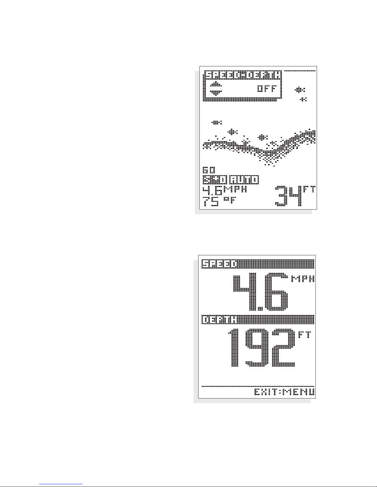
SPEED-DEPTH. The Speed-Depth
menu controls the display of a full
screen digital readout for boat
speed and depth.
To view the Speed-Depth screen,
use the
UP or DOWN arrow to
show the full screen display. The
current boat speed is displayed at
the top the screen, and current
depth at the bottom. At any time
you can return to the normal sonar
view by pressing the
MENU
button.
Note: The optional Speed &
Temperature accessory must
be connected for the SpeedDepth menu to be available.
USING THE 100ID SERIES
MENU FUNCTIONS
Speed-Depth Screen
Page 19
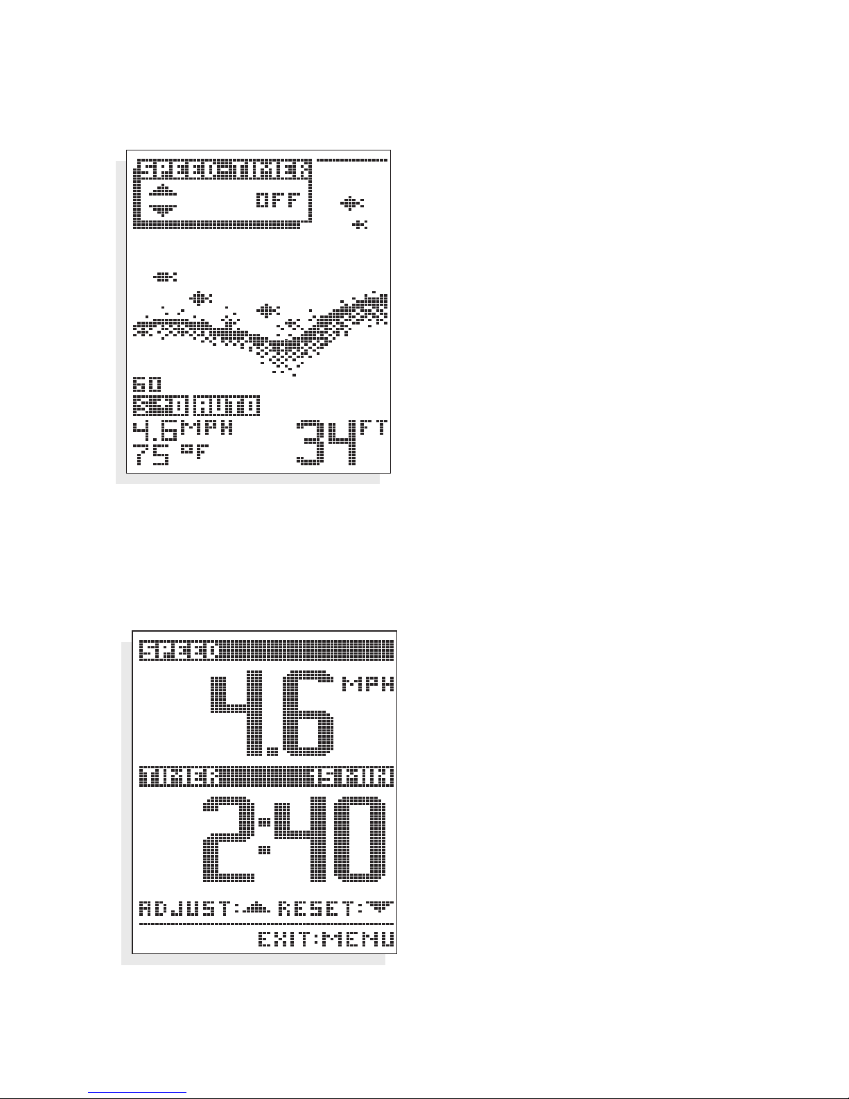
17
SPEED TIMER. The Speed-Timer menu
controls the display of a full screen
digital readout for boat speed and a
countdown timer.
To display the Speed-Timer screen,
use the
UP or DOWN arrow to show
the full screen display. Current boat
speed is displayed at top, and the
countdown timer at the bottom.
To set the countdown timer, use the
UP arrow to select one of the four
countdown presets: 0, 5, 10, or 15
minutes. The current countdown
timer setting is displayed above the
digital timer readout. Once you select
a setting other than zero minutes, the
countdown timer is activated and will
alarm when the timer reaches zero.
After alarming the timer will begin to
count up. Restart the timer by using
the
DOWN arrow.
At any time you can return to
normal sonar operation by pressing
the MENU button.
Note: The optional Speed &
Temperature accessory
must be connected for the
Speed-Timer menu to be
available.
USING THE 100ID SERIES
MENU FUNCTIONS
Speed-Timer Screen
Page 20

18
MAINTENANCE
Your Teleflex 100ID depthsounder is designed to provide you with years of
trouble-free operation with virtually no maintenance. Follow the simple
procedures below to ensure that your
100ID continues to deliver top perfor-
mance.
If the unit comes into contact with salt spray, simply wipe the affected
surfaces with a cloth dampened in fresh water.
When cleaning the LCD protective lens, use a chamois and non-abrasive,
mild cleaner. Do not wipe while dirt or grease is on the lens. Be careful to
avoid scratching the lens.
If your boat remains in the water for long periods of time, algae and other
marine growth can reduce the effectiveness of an externally mounted transducer. Periodically clean the face of the transducer with liquid detergent.
Pivoting the transducer up in the bracket may allow better access for inspection or cleaning.
If your boat remains out of the water for a long period of time, it may take
some time to wet the transducer when returned to the water. Small air
bubbles can cling to the surface of the transducer and interfere with proper
operation. These bubbles will dissipate with time, or you may wipe the face
of the transducer with your fingers after the transducer is in the water.
Do not attempt to repair the
100ID yourself. There are no user serviceable parts
inside, and special tools and techniques are required for reassembly to ensure
the integrity of the housing.
Repairs should be performed only by autho-
rized Techsonic technicians.
MAINTENANCE AND WARRANTY
MAINTENANCE
Page 21

19
TROUBLESHOOTING. Many requests for repair received by Techsonic involve
units that do not actually need repair. If you have trouble with your
100ID,
consult the following troubleshooting guide before contacting Techsonic.
1. Nothing happens when I turn the unit on.
Check the power cable connection and fuse. Be sure the power cable is properly
connected - red lead to 12 VDC positive, black lead to negative. Often a fuse can appear
to be good when in fact it is not. Check the fuse with a tester, or replace it if in doubt.
2. There is no bottom reading on the display when I press the power button.
Ensure that the transducer is properly attached to the 100ID unit. Also, make sure
that the transducer is fully submerged in the water, and that the water depth is not in
excess of the unit’s capability.
3. When in very shallow water, I get gaps in the bottom reading or the
depth range continuously changes to deeper ranges.
The 100ID is not able to operate in water 12" or less.
4. The unit is powered before I press power, and it won’t turn off.
Check the transducer cable - if the outer jacket has been cut and the cable is touching
metal, you will need to repair it with electrical tape. If you can’t find a problem with
the cable, disconnect the transducer from the unit to see if the problem is corrected. If
so, the problem is with the transducer cable.
5. I get gaps in the reading at high speeds.
Your transducer requires adjustment. If the transducer is transom mounted, there are
two adjustments available to you - height, and running angle. Make small adjustments and run the boat at high speed to determine the effect. It may take several
tries to optimize high speed operation.
6. My unit loses power at high speeds.
Your Teleflex Sonar unit has an over-voltage protection which turns the unit off when
input voltage exceeds 17 volts DC. Some outboard motors do not effectively regulate
output voltage and can produce electrical output in excess of 17 volts at higher
engine speeds. Pressing POWER when the output voltage returns to the required level
will restore your unit.
MAINTENANCE AND WARRANTY
TROUBLESHOOTING
Page 22

20
7. The display shows many black dots at high speeds and high
sensitivity settings.
What you are seeing on-screen is interference, normally caused by cavitation, or air bubbles in the vicinity of the transducer. Often the propeller is
the cause, and adequate separation between the transducer and the
propeller is necessary.
8. The bottom reading disappears during a hard turn.
This is normal as the transducer comes out of the water, and will correct
itself when the turn is complete.
9. The screen begins to fade out. Images on the screen are not as sharp
and clear as normal.
Check your battery to see that it’s fully charged - the
100ID
will not operate on less
than 10 VDC.
TECHSONIC ONE YEAR FULL WARRANTY
First year repairs (from original date of purchase) on your 100ID are
absolutely free. This does not include physical damage to the unit or its
accessory items. Any modification or attempt to repair the original
equipment or accessories by unauthorized individuals will void the
warranty. Return the warranty registration card and retain your bill of
sale for warranty verification. Accessories not manufactured under the
Techsonic Teleflex Sonar trade name are not covered by our warranty.
The customer is responsible for shipping charges to Techsonic.
This warranty applies to the original purchaser only.
This warranty is in lieu of all other warranties expressed or implied and no
representatives or persons are authorized to provide for any other liability
in connection with the sale of our products. Techsonic reserves the right
to perform modifications or improvements on its products without incurring the obligation to install the changes on units previously manufactured, sold, delivered, or serviced.
THIS IS A FULL WARRANTY AS DEFINED BY THE FEDERAL WARRANTY
ACT, EFFECTIVE JULY 4, 1975.
MAINTENANCE AND WARRANTY
ONE YEAR WARRANTY
Page 23

21
SERVICE POLICY
This Service Policy is valid in the United States only. This applies to Teleflex
Sonar units returned to our factory in Eufaula, Alabama, and is subject to
change without notice.
All repair work is performed by factory-trained technicians to meet exacting factory specifications. Factory serviced units go through the same rigorous testing and quality control inspection as new production units.
Even though you’ll probably never need to take advantage of our incredible service guarantee, it’s good to know that we back our units this well.
We do it because you deserve the best. We will make every effort to
repair your unit within three working days from the receipt of your unit.
This does not include shipping time to and from our factory. Units
received on Friday are usually shipped by Wednesday, units received
Monday are usually shipped by Thursday, etc.
We reserve the right to deem any product unserviceable when replacement
parts are no longer reasonably available or impossible to obtain.
After the original warranty period, a standard flat rate service charge will
be assessed for each repair (physical damage and missing parts are not
included). Please call our Customer Support Department to verify the
service charge for your unit.
If shipping charges are not prepaid, the unit will be returned C.O.D. If you
are experiencing problems related to bottom or depth readings, please
send your transducer along with your unit when sending for repair.
MAINTENANCE AND WARRANTY
SERVICE POLICY
Page 24

22
CUSTOMER SUPPORT
If you have any questions, call our Customer Support Hotline:
1-800-747-9329
Throughout the U.S. and Canada, hours are Monday-Friday, 8:00 a.m. to
5:00 p.m. Central time.
If after reading “Troubleshooting” you determine your unit needs factory
service, please attach a description of the problem and send it with the
unit to the address below.
If you are including a check, please attach it to the unit.
Techsonic Industries Inc.
Service Department
108 Maple Lane
Eufaula, AL 36027
USA
MAINTENANCE AND WARRANTY
CUSTOMER SUPPORT
Page 25

23
Operating Frequency . . . . . . . . . . . . . . . . . . . . . . . . . . . . . . . . . . . . . 200 kHz
Power Output . . . . . . . . . . . . . . . . . . . . . . . . . . . . . . . . . . . 250 Watts (RMS)
. . . . . . . . . . . . . . . . . . . . . . . . . . . . . . . . . . . . . . . . . 2000 (Peak to Peak)
Area of Coverage . . . . . . . . . . . . . . . . . . . . . . . . . . . . . . . . . . . .16° @ -10db
Power Requirement . . . . . . . . . . . . . . . . . . . . . . . . . . . . . . . . . . . .10-16 VDC
Display . . . . . . . . . . . . . . . . . . . . . . . . . . . . . . . . . . . . . . . . . Super Twist LCD
LCD Matrix . . . . . . . . . . . . . . . . . . . . . . . . . . . . . . . . . . . . . . . . . . . .100 x 64
Viewing Area . . . . . . . . . . . . . . . . . . . . . . . . . . . . . . . . . . . . . . 2.90" x 2.35"
Mounting . . . . . . . . . . . . . . . . . . . . . . . . . . . . . . . . . . . . . . . . . . . . . . In Dash
Unit Size . . . . . . . . . . . . . . . . . . . . . . . . . . . 4.38" square by 4.4" total depth
Unit Size On Dash . . . . . . . . . . . . . . . . . . . . . . . . 4.38"H x 4.38"W x .80"D,
Unit Dimensions, area needed under dash . . . . . . . . . 3.65" D, 3.5" dia. hole
Transducer (Standard) . . . . . . . . . . . . . . . . . . . . . . . . . . . . . . . . . . . XHS-6-16
Transducer Cable Length . . . . . . . . . . . . . . . . . . . . . . . . . . . . . . . . . . . . . . 20'
Depth Ranges . . . . . . . . . . . . . . . . . . . . . . . . . . . . . 15', 30', 60', 120', 180',
. . . . . . . . . . . . . . . . . . . . . . . . . . . . . . . . . . . . . 240', 360', 480' & 600'
Zoom Ranges . . . . . . . . . . . . . . . . . . . . . . . . . . . . . . . . . . . 7', 15', 30' & 60'
SPECIFICATIONS
Page 26

531049-1
Page 27

A Division of Teleflex Marine
 Loading...