

Teleflex CH1700, CH7500, CH7600 Installation Manual
User Manual: CH1700/7500/7600
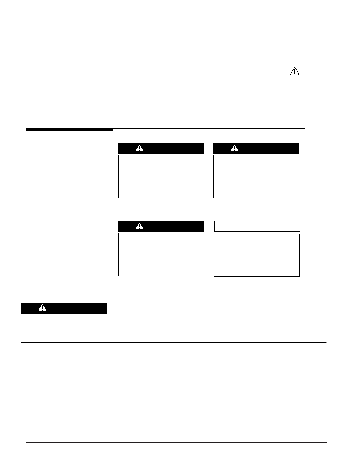
Notice to Boat Manufacturer, Installer, and Boat Operator
Throughout this manual, Warnings and Cautions (accompanied by the International Hazard Symbol ) are used
to alert the manufacturer or installer to special instructions concerning a particular service or operation that may
be hazardous if performed incorrectly or carelessly.
Warnings alone do not eliminate dangers, nor are they a substitute for safe boat handling and proper accident
prevention measures.
Observe these alerts carefully!
These “safety alerts” alone,
cannot eliminate the hazards
that they signal. Strict
compliance to these special
instructions when installing,
operating or performing
maintenance and using
common sense are the most
effective accident prevention
measures.
Immediate hazards which
DANGER
WILL result in severe
personal injury or death.
WARNING
Hazards or unsafe
practices which COULD
result in severe personal
injury or death.
NOTICE
to proper installation,
operation or maintenance,
but is not hazard-related.
For example:
CAUTION
CAUTION
Hazards or unsafe
practices which COULD
result in injury, product
and/or property damage.
Do not tighten cable hangers or clamps to the extent that
Information that is important
they crush or stress the cables in any way. Doing so may
impair the function of the cable.
The information contained in this manual is believed to be accurate at the time of going to print but no responsibility,
direct or consequential, can be accepted for damage resulting from the use of this information. The manufacturer
reserves the right to make changes, without notice, to any of its products.
ISCH7500_Rev2 (2)

User Manual: CH1700/7500/7600
INTRODUCTION
This Teleflex Marine Control provides both shift and throttle operation for inboards, outboards, and
inboard/outboards.
We recommended the use of Teleflex TFXtreme™ engine cables.
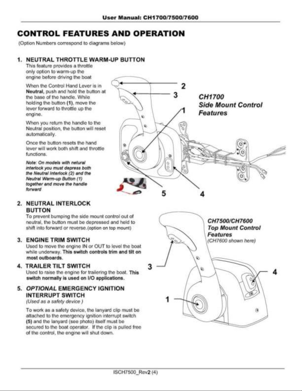
Control Features
Single Lever Shift and Throttle Operation
Neutral Throttle Warm-Up
Neutral Throttle Interlock
Neutral Safety Switch (to prevent starting in gear)
Friction Adjust Screw (to prevent throttle "creep")
Control Options
Trim Switch
Trim & Tilt Switch
Emergency Ignition Interrupt Switch & Lanyard
Other Parts Required for Installation
Quantity Part
2
Control Cables
Check section 2 of installation instructions for routing and length. Teleflex TFXtreme™ cables
are recommended.
Side Mount
CH1700
9
Top Mount
CH7500 / CH7600
9
99
9
9
9
Option Option
Option Option
Option
Option
9
9
n/a
Adaptability
Control Cable
This control will connect to ANY current 3300-/OEM-type control cable. A cable nest kit (also known as a
quick-connect adapter; part #212151-001), which mates to the engine’s shift and throttle cable, is included
with this control. Unique cable nests, which are required for Mercury Gen II Engines only, are included with
the control connection kit.
ISCH7500_Rev2 (3)
User Manual: CH1700/7500/7600
INSTALLATION
Section 1: Location of Control
1.1 Allow adequate clearance for hand lever swing (forward and reverse positions).
1.2 Allow adequate clearance under the console or in the gunwale for the cables AND allow a minimum of 36”
from the cable nest connection with no restraint. When supporting the cables beyond 36”, do not tie or
clamp tightly.
1.3 After a suitable location for the control is determined, use the separate mounting template.
1.4 Closely follow the instructions provided on the template. Cut & drill the mounting holes required.
On all models, the cover will have to be removed to expose the mounting holes.
Tools for Installation
Phillips head screwdrivers Power drill 5/8” or 16mm deep well socket
Standard slot screwdriver 7/32” & 17/64” drill bits Ratchet wrench
Saber saw 3/8” box end wrench
4¼ “ Hole Saw (optional) Multimeter (optional)
Section 2: Measuring the Cables
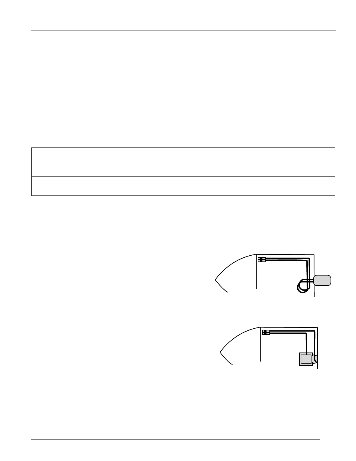
Measure the cable routing path from the control head connection to the engine connection.
Outboards:
Measure from the control connection -- along an unobstructed cable
routing --to the center of the outboard engine.
Add four (4) feet to the measurement to allow for a loop which
provides unrestricted engine movement. Round UP to the next
whole foot and order the required cable part number.
(Last two digits of the Teleflex cable number equal the length of the
cable in feet.)
Inboards & Stern Drives:
Measure from the control connection -- along an unobstructed cable
routing -- to the SHIFT or THROTTLE connection. Round this
dimension UP to the next whole foot and order the required cable
part number.
(Last two digits of the Teleflex cable number equal the length of the
cable in feet.)
ISCH7500_Rev2 (5)
User Manual: CH1700/7500/7600
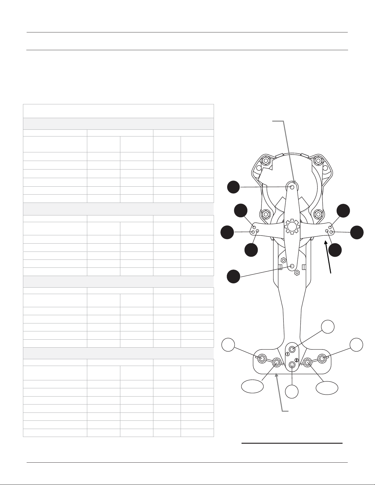
Section 3: Shift & Throttle Cable Connection - Control End
xPUSH / PULL refer to the direction of cable motion to shift into "forward" or to "open" the throttle
x Refer to the appropriate manufacturer’s manual for shift and throttle direction and adjustments
xNumbered holes on mechanism chassis correspond to holes in shift and throttle levers
(for example: connect cable mount to hole 4 on chassis and cable end fitting to hole 4 on lever)
x Cables and wiring should be pre-installed on control before final mounting is made
Cable Connection Guide
PUSH to OPEN THROTTLE
CH1700/ CH7600 CH7500
MANUFACTURER
MERCURY18 & 25 HP # 1 # 1
JOHNSON / EVINRUDE # 1 # 1
BRP/OMC I/O # 1 # 1
YAMAHA 90HP & UP # 1 # 1
US MARINE # 1 # 1
SUZUKI # 1 # 1
MANUFACTURER
MERCURY I/O & O/B
VOLVO I/O
YAMAHA 70HP & UNDER
HONDA
NISSAN/TOHATSU
MANUFACTURER
VOLVO I/O & INBOARDS
3300 CABLES
MERCURY18 & 25 HP
EVINRUDE / JOHNSON
INBOARDS
MANUFACTURER
3300 CABLES
MERCURY
EVINRUDE/JOHNSON
HONDA/NISSAN/SUZUKI
TOHATSU/ US MARINE
YAMAHA
INBOARDS
CABLE
NEST KIT
PULL to OPEN THROTTLE
CH1700/ CH7600 CH7500
CABLE
NEST KIT
# 2 # 2 # 2 # 2
# 2 # 2 # 2 # 2
# 2 # 2 # 2 # 2
# 2 # 2 # 2 # 2
# 2 # 2 # 2 # 2
PUSH for FORWARD SHIFT
CH1700/ CH7600 CH7500
CABLE
NEST KIT
# 3 # 3 # 4 # 4
# 3 # 3 # 4 # 4
# 5/6 # 6 # 7/8 # 7
# 5/6 # 5 # 7/8 # 8
# 3 # 3 # 4 # 4
PULL for FORWARD SHIFT
CH1700/ CH7600 CH7500
CABLE
NEST KIT
# 4 # 4 # 3 # 3
# 7/8 # 7 # 5/6 # 6
# 7/8 # 8 # 5/6 # 5
# 4 # 4 # 3 # 3
# 4 # 4 # 3 # 3
# 4 # 4 # 3 # 3
# 4 # 4 # 3 # 3
THROTTLE
LEVER
THROTTLE
LEVER
SHIFT
LEVER
SHIFT
LEVER
CABLE
NEST KIT
# 1 # 1
# 1 # 1
# 1 # 1
# 1 # 1
# 1 # 1
# 1 # 1
CABLE
NEST KIT
CABLE
NEST KIT
CABLE
NEST KIT
THROTTLE
LEVER
THROTTLE
LEVER
SHIFT
LEVER
SHIFT
LEVER
Throttle
Lever
1
3
6
5
2
3
5/6
2
Cable Nest
Bracket
Cable Mounting Diagram
4
77
8
Shift
Lever
1
4
7/8
ISCH7500_Rev2 (6)
 Loading...