

Page 1
Operator’s
Manual
ZS
Series
High
-Impedance
Active Probe
s
Page 2

Page 3

ZS1000, ZS1500, ZS2500
High-Impedance Active Probes
Operator’s Manual
April, 2017
Page 4

ZS Series High-Impedance Active Probes Operator’s Manual
© 2017 Teledyne LeCroy, Inc. All rights reserved.
Unauthorized duplication of Teledyne LeCroy documentation materials other
than for internal sales and distribution purposes is strictly prohibited.
However, clients are encouraged to distribute and duplicate Teledyne LeCroy
documentation for their own internal educational purposes.
Teledyne LeCroy is a registered trademark of Teledyne LeCroy, Inc. Windows
is a registered trademark of Microsoft Corporation. Other product or brand
names are trademarks or requested trademarks of their respective holders.
Information in this publication supersedes all earlier versions. Specifications
are subject to change without notice.
928327-00 Rev A
April 2017
Page 5

Operator’s Manual
i
Warranty
Teledyne Lecroy warrants this oscilloscope accessory for normal use and
operation within specification for a period of one year from the date of
shipment. Spare parts, replacement parts and repairs are warranted for 90
days.
In exercising its warranty, Teledyne LeCroy, at its option, will either repair or
replace any assembly returned within its warranty period to the Customer
Service Department or an authorized service center. However, this will be
done only if the product is determined by Teledyne LeCroy’s examination to be
defective due to workmanship or materials, and the defect is not caused by
misuse, neglect, accident, abnormal conditions of operation, or damage
resulting from attempted repair or modifications by a non-authorized service
facility.
The customer will be responsible for the transportation and insurance
charges for the return of products to the service facility. Teledyne LeCroy will
return all products under warranty with transportation charges prepaid.
This warranty replaces all other warranties, expressed or implied, including
but not limited to any implied warranty of merchantability, fitness or adequacy
for any particular purposes or use. Teledyne LeCroy shall not be liable for any
special, incidental, or consequential damages, whether in contract or
otherwise.
Page 6

ZS Series High-Impedance, Active Probes
ii
Table of Contents
Safety Instructions ................................................................................ 1
Introduction ........................................................................................... 2
Standard Accessories ............................................................................ 3
Tips ......................................................................................................... 4
Grounds .................................................................................................. 5
Leads ...................................................................................................... 6
Clips and Grabbers ................................................................................ 6
Probe Holder .......................................................................................... 7
Probe Impedance and Equivalent Circuits .......................................... 8
Probe Operation .................................................................................. 10
Handling the Probe .............................................................................. 10
Connecting the Probe to the Test Circuit .......................................... 10
Connecting the Probe to an Oscilloscope ......................................... 10
Operation with a Teledyne LeCroy Oscilloscope ............................... 11
Auto Zero .............................................................................................. 11
High Frequency Measurements ......................................................... 12
Care and Maintenance ......................................................................... 16
Cleaning ................................................................................................ 16
Calibration Interval .............................................................................. 16
Service Strategy ................................................................................... 16
Replacement Parts .............................................................................. 16
Performance Verification ..................................................................... 17
Required Test Equipment ................................................................... 17
Test Setup and Preliminary Procedure .............................................. 19
Functional Check ................................................................................. 19
Verification Procedure ........................................................................ 20
ZS Series Probe Test Record .............................................................. 24
Reference Material .............................................................................. 25
Page 7

Operator’s Manual
1
Safety Instructions
Observe generally accepted safety procedures in addition to the precautions
listed here. The overall safety of any system incorporating this accessory is
the responsibility of the assembler of the system.
Symbols
These symbols appear on the probe body or in documentation to alert you to
important safety considerations.
CAUTION of potential for damage to equipment, or WARNING of
potential for bodily injury. Attend to the information, and do not
proceed until conditions are fully understood and met.
ELECTROSTATIC DISCHARGE (ESD) HAZARD. The probe is
susceptible to damage if anti-static measures are not taken.
Precautions
Connect and disconnect properly. Connect probe to the measurement
instrument before connecting the test leads to a circuit/signal being tested.
Use only within operational environment listed. Do not use in wet or
explosive atmospheres.
Use indoors only.
Keep product surfaces clean and dry.
Be careful with sharp tips. The tips may cause bodily injury if not handled
properly.
Use only accessories designed for use with the product.
Observe all terminal ratings. To avoid electric shock or probe damage, do not
use the probe above the input limits shown on the probe.
Do not excessively bend cables.
Do not operate with suspected failures. Do not use the probe if any part is
damaged. Cease operation immediately and secure the probe from
inadvertent use.
Page 8

ZS Series High-Impedance, Active Probes
2
Operating Environment
The accessory is intended for indoor use and should be operated in a clean,
dry environment. Before using this product, ensure that its operating
environment is maintained within these parameters:
Temperature: 0 to 40° C
Humidity: Maximum relative humidity 80 % for temperatures up to 31 °C
decreasing linearly to 50 % relative humidity at 40° C
Altitude: Up to 10,000 ft (3,048 m)
Introduction
The ZS Series (ZS1000, ZS1500, and ZS2500) are a small, high-impedance
active probes designed to meet today’s increasing demand for
measurements on a variety of test points. With low input capacitance and
high input resistance, circuit loading is minimized.
The ZS probes can be used with a variety of Teledyne LeCroy oscilloscopes
with MAUI firmware version 6.5.0.5 or later (see the product page at
teledynelecroy.com/oscilloscope for compatibility). With the ProBus
interface, the probe becomes an integral part of the oscilloscope, controlled
from the oscilloscope’s front panel. The oscilloscope provides power to the
probe, so there is no need for a separate power supply or batteries.
See the ZS product page at teledynelecroy.com for probe specifications.
Key Benefits
Features
High frequency performance
Low input capacitance
Wide dynamic range
ProBus interface
Small, low mass probe head is designed
for ease of use and high performance.
Probe tip socket fits easily onto 0.025
inch square pins for direct access to
test points. Several available adaptors
connect directly to the probe socket.
Ground socket accepts several different
ground leads to provide a short ground
path for high frequency performance.
Page 9

Operator’s Manual
3
Standard Accessories
ZS Series probes are shipped with the following standard accessories:
Standard Accessory
QTY
Replacement Part Number
Straight Pin Lead – Short
1
PK-ZS-003
Straight Pin Lead – Long
1
PK-ZS-004
Right Angle Lead – Short
1
PACC-LD003
Right Angle Lead – Long
1
PACC-LD004
Y Lead Adapter
1
PK-ZS-005
Micro-Grabber Pair
1
PK-ZS-007R and PK-ZS-007B
Ground Blade – Wide
1
PK-ZS-011
Probe Tip – Standard
3
PK-ZS-001
Right Angle Socket
1
PK-ZS-006
Offset Ground – Z Lead
1
PK-ZS-002
Ground Blade – Narrow
1
PK-ZS-008
Copper Tape
2
PK-ZS-009
Pogo Tip
1
PK-ZS-013
2.54mm Square Pin Adapter
1
PK-ZS-012
Channel ID Clips (1 set of 4)
4
PK-ZS-010
Freehand Probe Holder
1
PACC-MS005
Bent Tip
1
PACC-PT005
IC Tip
1
PACC-PT003
Pogo Ground Lead
1
PACC-CD008
Operator’s Manual
1
N/A*
Certificate of Calibration
1
ZS-CC
* PDF copy of this manual available free at teledynelecroy.com/support/techlib.
Page 10
ZS Series High-Impedance, Active Probes
4
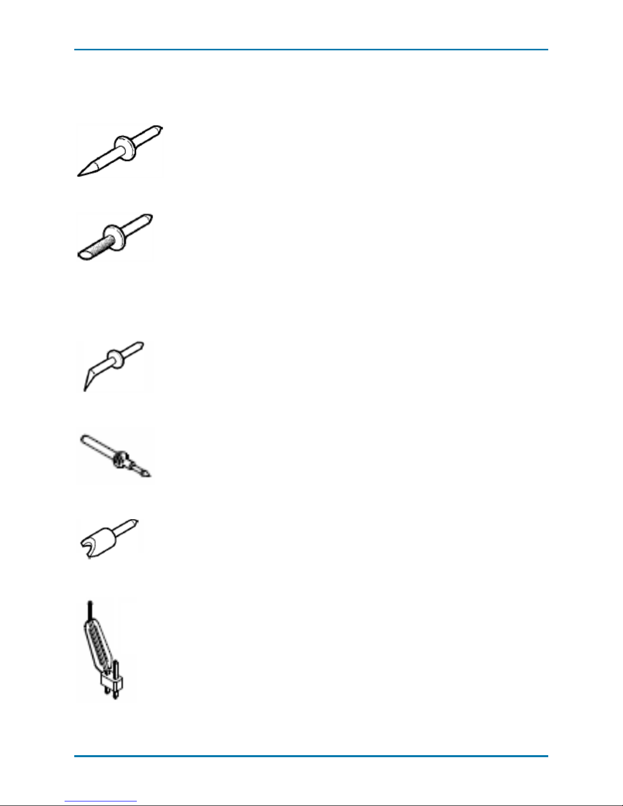
Tips
Straight Tip
The straight tip is rugged and designed for
general probing. Fits in either probe socket.
IC Lead Tip
The IC Lead Tip is covered in insulation on all
si
des (except for a small edge). This tip was
designed to prevent shorting neighboring IC
leads. The gold part of the tip is not insulated and
should touch the IC lead to be tested. It is one
-
size
-fits-all and will work with any IC lead pitch.
Fits in either probe socket.
Bent Tip
The Bent Tip is made out of titanium, this tip is
ideal for situations that require
you to hold the
probe parallel to the circuit board under test. Also
gives you more control when holding the probe
like a pencil. Fits in either probe socket.
Pogo Tip
The pogo tip provides z-axis compliance. The tip
can fit into a socket or onto a
n IC leg.
Discrete SMD Tip
The crescent shape of this tip is designed to fit
tightly on capacitors, resistors, transistors and
other surface mount components with discrete
leads. Fits in either probe socket
.
2.54mm Square Pin Adapter
2.54 mm Square Pin Adapter. The 2.54 mm
square pin adapter fits into both the
input and
ground lead of the ZS probe for easy connection
to standard 2.54 mm square pin spacing on a
circuit board.
Page 11

Operator’s Manual
5
Grounds
Offset Ground
The Offset Ground is designed to be attached to
either socket of the probe head. The
Offset
Ground
connects to the ground socket and wraps
around the probe head
, making it possible to
probe a
signal and ground that are extremely
close together. The short length provides
the
high
est quality grounding for high frequency
applications.
Narrow Ground Blade and
Copper Pad
The Narrow Ground Blade and Copper Pad
together are
the best grounding solution for
probing an IC. The
Narrow Ground Blade is
designed to provide a short, low inductance
ground path. The Copper Pad is adhesive backed
to stick to the top of an
IC, and can then be
soldered to the IC ground.
Wide Ground Blade
The Wide Ground Blade is ideal for use when the
best quality ground is needed. The wide blade
offers the minimal inductance compared to the
narrow ground blade.
Page 12

ZS Series High-Impedance, Active Probes
6
Leads
While longer leads provide greater flexibility when connecting the probe to a
circuit, the added inductance may degrade the fidelity of high frequency
signals.
Short and Long
Straight Pin Lead
These leads have a socket on one end and a
square pin on the other to connect
to the input or
ground socket of the probe body, and may be
used for general purpose probing.
Short and Long
Right Angle Pin Lead
These leads have a socket on one end with a right
angle and a square pin on the other to connect to
the input or ground socket of the probe body, and
may be used for general purpose probing.
Y Lead
This lead is used for both ground and input lead
simultaneously. It has two sockets on one end
and two square pins on the other and may be
used for general purpose probing.
Clips and Grabbers
Channel ID Clips
The Channel ID Clips can be attached to the
probe cable to quickly identify to which channel
the probe is currently connected: CH1 yellow, CH2
red, CH3 green, and CH4 blue.
Micro-Grabbers
The micro-grabbers are ideal for connecting to
small IC legs or pins very tightly spaced.
Page 13

Operator’s Manual
7
Probe Holder
Freehand Probe Holder
The FreeHand lets you focus on the oscilloscope
screen instead of on maintaining contact to
multiple test points. It allows
you to concentrate
on what is re
ally important – the waveform.
It is designed to keep most of the weight on the
probe tip and will prevent lost contact when a
bump to the table shakes the circuit under test.
Page 14

ZS Series High-Impedance, Active Probes
8
Probe Impedance and Equivalent Circuits
ZS1x00 Impedance Chart
ZS1x00 Equivalent Circuit
10
100
1000
10000
100000
1000000
10Hz 100Hz 1kHz 10kHz 100kHz 1MHz 10MHz 100MHz 1000MHz10000MHz
Page 15

Operator’s Manual
9
ZS2500 Impedance Chart
ZS2500 Equivalent Circuit
1
10
100
1000
10000
100000
1000000
100Hz 1kHz 10kHz 100kHz 1MHz 10MHz 100MHz 1000MHz 10000MHz
Page 16

ZS Series High-Impedance, Active Probes
10
Probe Operation
Handling the Probe
The ZS Series probes are precision test instruments. Exercise care when
handling and storing the probe. Always handle the probe by the probe body or
compensation box. Avoid putting excessive strain or exposing the probe
cable to sharp bends.
ESD Sensitive: The tips of the probes are sensitive to Electrostatic
Discharge (ESD). Avoid causing damage to the probe by always
following anti-static procedures (wear wrist strap, etc.) when using
or handling the probe.
Connecting the Probe to the Test Circuit
To maintain the high performance capability of the probe in measurement
applications, care must be exercised in connecting the probe to the test
circuit. Increasing the parasitic capacitance or inductance in the input paths
may introduce a “ring” or slow the rise time of fast signals. Input leads which
form a large loop area will pick up any radiated electromagnetic field which
passes through the loop and may induce noise into the probe input.
Using one of the available accessories makes the ZS probe with its small
profile and low mass head ideally suited for applications in dense circuitry.
Connecting the Probe to an Oscilloscope
ZS Series probes are designed for use with Teledyne LeCroy platforms
equipped with the ProBus interface. When you attach the probe output
connector to the oscilloscope’s input connector, the oscilloscope recognizes
the probe, provides proper termination, and activates the probe control
functions in the user interface.
Page 17

Operator’s Manual
11
Operation with a Teledyne LeCroy Oscilloscope
When the ZS probe is connected to any compatible Teledyne LeCroy
oscilloscope, the displayed scale factor and measurement values are
automatically adjusted. A Probe dialog appears behind the corresponding
Channel dialog.
The probe can be controlled through the oscilloscope front panel:
• The Volts/Div knob controls the oscilloscope’s scale factor to give
full available dynamic range up to 2 V/div (16 V peak to peak).
• The channel Offset knob controls the probe input offset circuit over
its range of ±12 V.
Auto Zero
Auto Zero corrects for DC offset drifts that naturally occur from thermal
effects in the amplifier. The probe incorporates Auto Zero capability to
remove the DC offset from the probe's amplifier output to improve the
measurement accuracy.
Auto Zero is invoked manually from the ZSxxxx probe dialog that appears
when the probe is connected to the oscilloscope.
Always perform Auto Zero after the probe is warmed up (recommended
warm-up time is 20 minutes). Depending on the measurement accuracy
desired and/or changes in ambient temperature where the probe is located, it
may be necessary to perform Auto Zero more often. If the probe is
disconnected from the oscilloscope and reconnected, repeat Auto Zero after
a suitable warm-up time.
CAUTION: Disconnect the probe from the circuit before Auto Zero, or
else any DC component that is part of the Signal to be measured will
be zeroed out.
Page 18

ZS Series High-Impedance, Active Probes
12
High Frequency Measurements
Probe Input Loading
When you touch a probe to the circuit under test, the probe will affect your
measurement because of the probe’s input impedance introduced into the
circuit. All probes present resistive, capacitive and inductive loading.
Inductive Loading (Lead Length)
A significant element in this circuit is the inductance shown in the input
ground leads of the oscilloscope probe.
Probe input equivalent circuit
The ground lead is the primary return path for the current resulting from the
input voltage acting on the probe’s input impedance. The ground lead and
input lead inductances act with the probe’s input capacitance to form series
LC network. The impedance of a series LC network drops dramatically at its
resonant frequency. This is the cause of the "ring" we often see after the
leading edge of pulses in measured waveforms.
This effect is referred to as ground lead corruption. Because it is impossible
to eliminate either the L or C from this circuit, the method to improve
waveform fidelity is to raise the resonant frequency beyond the bandwidth of
interest in the measurement.
The resonant frequency of a simple LC circuit can be represented by:
=
1
2√
The resonant frequency of a series LC circuit can be raised by decreasing the
inductance, capacitance or both. Since the input capacitance is already very
Page 19

Operator’s Manual
13
low and cannot be reduced, you can only try to reduce the inductance. This
can be accomplished by using the shortest possible input lead as well as the
shortest possible ground lead.
For example, to obtain the shortest possible ground lead when measuring IC
related signals, attach a small piece of copper clad material to the top of the
IC package and connect this to the package grounding wires.
Using the shortest ground lead and input lead available makes probing
signals on the package easier and makes for the shortest lead length for the
best signal fidelity. To illustrate how dramatic this effect is, we will work a
simple example. Assuming an input capacitance of 0.9 pF and a total lead
length (input and ground) of 2 inches (inductance of ≈ 25 nH/inch) such a
setup may cause ringing with a resonant frequency (f0) of:
=
1
2√50 ∗ 10
−9
∗ 0.9 ∗ 10
−12
= 750
This frequency is well within the passband of the probe and therefore shows
up as part of the measured signal at faster time/div settings.
To determine how fast a waveform to be measured can be without causing
ringing on a probe like this, divide the BW (ringing frequency) of the probe
into 0.35:
=
0.35
=
0.35
750
= 0.47
Any input signal with a rise time faster than 0.47 ns can cause ringing.
Page 20

ZS Series High-Impedance, Active Probes
14
Capacitive Loading
Capacitive loading is usually the most troublesome of the three loading
effects. It can affect the rise time, bandwidth and delay time measurements.
At higher frequencies the capacitive loading can affect the amplitude as well
as the waveshape of the measured signal by introducing an exponential
response to the waveform.
For a simple RC network the time constant of this exponential response is:
= 2.2 ×
×
Where
C
total
is the combined probe and circuit capacitance and
R
total
is
combined circuit and probe resistance.
For a setup where Ct = 0.9 pF and a source resistance is 250 Ω, the
measured rise time will be 0.495 ns, which will correspond to a bandwidth of
909 MHz, assuming no inductive loads.
= 2.2 × 0.9 × 10
−12
× 250 Ω = 0.495 ns
Parallel combination of 250 Ω and 1 MΩ is still 250 Ω
Example probe input equivalent circuit
To illustrate the effect of capacitive loading at higher frequencies:
• At frequency 750 MHz the reactance of the 0.9 pF capacitance is 236 Ω
• At frequency 1.0 GHz the reactance has been lowered to 177 Ω
If, at a given frequency, the source impedance is large with respect to the
input impedance, a measurable reduction in the output signal amplitude may
occur.
=
+
×
Page 21

Operator’s Manual
15
where
Z
probe
is the probe’s input impedance and
Z
source
is the source
impedance.
For example: At 750 MHz, where the probe input impedance has reduced to
236 Ω, and a source resistance of 250 Ω the probe output amplitude is
reduced to:
=
236
236 + 250
= 0.49 ∗
Page 22

ZS Series High-Impedance, Active Probes
16
Care and Maintenance
Cleaning
The exterior of the probe and cable should be cleaned using a soft cloth
moistened with water. Abrasive agents, strong detergents, or other solvents
may damage the probe. Always ensure that input leads are free of debris.
CAUTION. The probe case is not sealed and should never be immersed
in any fluid.
Calibration Interval
The recommended calibration interval is one year from the time the probe is
put into service. The complete performance verification procedure should be
performed as the first step of annual calibration.
Service Strategy
The ZS probes utilize fine pitch surface mount devices. It is therefore
impractical to attempt to repair in the field. Defective probes must be
returned to a Teledyne LeCroy service facility for diagnosis and exchange.
Defective probes under warranty are repaired or replaced. A probe that is not
under warranty can be exchanged for a factory refurbished probe for a
modest fee. You must return the defective probe in order to receive credit for
the probe core.
Replacement Parts
The probe connection accessories and other common parts can be ordered
through the North America Customer Care Centers. Refer to the Standard
Accessories table (p.3).
Page 23

Operator’s Manual
17
Performance Verification
This procedure can be used to verify the warranted characteristics of a ZS
Series High Impedance Active Probe. It tests:
• Output Zero Voltage
• LF Attenuation Accuracy
Performance verification can be completed without removing the probe
covers or exposing the user to hazardous voltages.
NOTE: The correct operation of the ZS probe controls requires software
version 6.5.0.5 or higher. The oscilloscope software version can be verified
by going to Utilities > Utilities Setup > Status. Contact your local Teledyne
LeCroy representative or visit teledynelecroy.com if the software in your
oscilloscope requires updating.
Required Test Equipment
This procedure has been developed to minimize the number of calibrated test
instruments required. Only equipment listed in boldface must be calibrated to
the accuracy indicated. Because the input and output connector types may
vary on different brands and models of test instruments, additional adaptors
or cables may be required.
The warranted characteristics of the probe are valid at any temperature
within the Operating Environment (p.2) listed in this manual. However, some
of the other test equipment used to verify the performance may have
environmental limitations required to meet the accuracy needed for the
procedure. Be sure that the ambient conditions meet the requirements of all
the test equipment used in his procedure.
NOTE: The function generator used in this Performance Verification
Procedure is used for making relative measurements. Because the output of
the generator is measured with an oscilloscope in this procedure, it is not
required to calibrate the generator.
Page 24

ZS Series High-Impedance, Active Probes
18
Description
Minimum Requirement
Example Equipment
Oscilloscope
ProBus Interface;
Windows-based
Teledyne LeCroy
WaveRunner 8000 or
HDO 6000
Digital
Multimeter
(DMM) with test
probe leads
4.5 digit
DC: 0.1% Accuracy
AC: 0.1% Accuracy
Keysight 34401A
Fluke 8842A-09
Function
Generator
Sine Wave output
Amplitude adjustable to
14.14 Vp-p (5 Vrms) into
1 MΩ at 70 Hz
Keysight 33120A
Stanford Research DS340
Power Supply
0-12 V, settable to 10 mV
HP E3611A
BNC Coaxial
Cable (2 ea.)
Male to Male, 50 Ω,
36" Cable
Pomona 2249-C-36
Pomona 5697-36
BNC Tee
Connector
Male to Dual Female
Pomona 3285
Calibration
Fixture
ProBus Extender Cable
Teledyne LeCroy
PROBUS-CF01
Terminator,
Precision, BNC
50 Ω ± 0.05%
Teledyne LeCroy
TERM-CF01
Banana Plug
Adapter (2 ea.)
Female BNC to Dual
Banana Plug
Pomona 1269
BNC to
Mini-grabber
BNC Mail to Mini-grabber
Cable, 36”
Pomona 5187-C-36
Page 25

Operator’s Manual
19
Test Setup and Preliminary Procedure
1. Connect the probe to the female end of the ProBus Extension Cable.
Connect the male end of the ProBus Extension Cable to channel 1 of the
oscilloscope.
2. Turn on the oscilloscope and allow at least 20 minutes warm-up time for
the probe and oscilloscope before performing the Verification Procedure.
3. Turn on the other test equipment and allow them to warm up for the
manufacturer’s recommended timeframe.
4. While the instruments are reaching operating temperature, make a
photocopy of the Performance Verification Test Record and fill in the
necessary data.
Functional Check
The functional check verifies the basic operation of the probe functions.
Perform the Functional Check prior to the Performance Verification.
1. Return to the factory default settings:
• Choose File > Recall Setup from the menu bar.
• Touch the Recall Default button.
2. Touch the C1 descriptor box to open the C1 dialog.
3. Verify that the probe is sensed and the correct model displayed on
the probe dialog tab behind the C1 dialog.
Page 26

ZS Series High-Impedance, Active Probes
20
Verification Procedure
A. Output Zero Voltage
Output Zero Voltage Test Setup
1. Connect one end of a BNC cable to the female BNC connector on the
probe end of the ProBus extender cable. Connect the precision 50 Ω
terminator to the other end of the BNC cable.
2. Connect the banana plugs of the Precision terminator to the input of the
DMM. Make sure that the plug corresponding to the BNC shield (marked
"Ground") is connected to the LOW or COMMON input of the DMM.
3. Set the OFFSET on the oscilloscope to zero.
4. Set the DMM to read DC Volt on the most sensitive range.
5. Record the voltage measured on the DMM to 100 μV resolution as
"Output Zero Voltage" in the Test record.
6. Check that the voltage indicated by the DMM is between ±1.0 mV.
7. Disconnect the DMM from the precision 50 Ω terminator. Leave the
remaining setup in place for the next test.
Page 27

Operator’s Manual
21
B. LF Attenuation Accuracy
LF Attenuation Accuracy Setup
1. Disconnect the BNC tee at the power supply from the dual banana plug
adapter. Connect the BNC tee to the output of the function gen erator.
(Use a 50 Ω termination if the function generator requires such a load.)
2. Carefully insert the Straight Tips (supplied in accessory kit) into the
sockets of the probe head. Attach the red lead of the mini-grabber to the
signal input and the black lead to the ground input of the probe head.
3. Connect the BNC tee to the output of the function generator. (Use a 50 Ω
termination if the function generator requires such a load).
4. Attach a BNC cable to the unused female port of the BNC tee and
connect a dual banana plug adapter to the other end of the cable and
plug the dual banana plug adapter into the DMM input. Be sure the side
of the banana plug adapter corresponding to the BNC shield (marked
"GROUND") is connected to the LOW or COMMON input of the DMM.
Page 28

ZS Series High-Impedance, Active Probes
22
5. Set the DMM to read AC volt and set the range to measure 5.0 Vrms.
6. Set the mode of the function generator to sine wave, the frequency to 70
Hz and the output amplitude to 5 Vrms ±10 mV as measured on the
DMM.
7. Record the output voltage to 1 mV resolution as "Generator Output
Voltage" in the Test Record. Be careful not to alter the output amplitude
after the reading is recorded.
8. Divide the reading recorded in step B-7 by 10 and record the result with
100 μV resolution as "Expected Output Voltage, top range" in the Test
Record.
9. Remove the banana plug adapter, connected to the function generator,
from the DMM and connect the precision 50 Ω terminator to the DMM,
making sure that the banana plug side marked "GROUND" is connected
to the LOW or COMMON input of the DMM.
10. After the DMM reading has stabilized, record the reading to 100 μV
resolution as "Measured Output Voltage, top range" in the Test Record.
11. Calculate the error by dividing the measured top range output voltage
recorded in step B10 by the expected top range output voltage recorded
in step B-8. Subtract 1 from this ratio and multiply by 100% to get the
error in percent.
12. Record the calculated error to two decimal places (±0.xx%) as "Gain Error,
top range" in the test record.
13. Verify that the error is less than ±1.0 %.
14. Disconnect the precision 50 Ω terminator from the DMM.
15. Connect the banana plug adapter connected via a BNC cable to the BNC
tee at the function generator to the DMM. Verify that the side of the plug
marked ’Ground’ is connected to the LOW or COMMON input of the DMM.
16. Adjust the sine wave generator output amplitude to approximately 2.5
Vrms as measured on the DMM.
17. Record the reading to 1 mV resolution as "Generator Output Voltage, mid
range" in the Test Record. Be careful not to alter the output amplitude
after the reading is recorded.
Page 29

Operator’s Manual
23
18. Divide the reading recorded in step B-17 by 10.
19. Record the result to 100 μV resolution as "Expected Output Voltage, mid
range" in the test record.
20. Remove the banana plug adapter from the DMM and connect the
precision 50 Ω terminator to the DMM, making sure that the banana plug
side marked "GROUND" is connected to the LOW or COMMON input of the
DMM.
21. After the DMM has stabilized, record the reading to 100 μV resolution as
"Measured Output Voltage, mid range" in the Test record.
22. Calculate the error by dividing the measured mid range output voltage
recorded in step B-21 by the expected mid range output voltage recorded
in step B-19. Subtract 1 from this ratio and multiply by 100% to get the
error in percent.
23. Record the calculated error to two decimal places (±0.xx %) as "Gain
Error, mid range" in the Test record.
24. Verify that the mid range gain error is less than ±1.0%
This completes the Performance Verification of the ZS probe. Complete and
file the Test Record, as required to support your internal calibration
procedure.
Apply suitable calibration label to the probe housing as required.
Page 30

ZS Series High-Impedance, Active Probes
24
ZS Series Probe Test Record
Technician:_____________________________________________
Date:_____________________
Equipment Used
Equipment
Model
Serial Number
Cal Due Date
Oscilloscope
Digital Multimeter
Function Generator
Probe
Lead
Tip
Test Record
OUTPUT ZERO VOLTAGE
Step
Description
Results
A-4
Output Zero (Test limit ≤ ±1.0 mV)
mV
LF ATTENUATION ACCURACY
Step
Description
Results
B-7
Generator Output Voltage
V
B-8
Expected Output Voltage, top range
V
B-10
Measured Output Voltage, top range
V
B-12
Gain Error, top range (Test Limit ≤ ± 1.0%)
%
B-17
Generator Output Voltage
V
B-19
Expected Output Voltage, mid range
V
B-21
Measured Output Voltage, mid range
V
B-23
Gain Error, mid range (Test Limit ≤ ± 1.0%)
%
Permission is granted to photocopy this page to record the results of the Performance
Verification procedure. The test limits are included in each step. Create a new record for each
probe, lead, and tip combination.
Page 31

Operator’s Manual
25
Reference Material
Certifications
Teledyne LeCroy certifies compliance to the following standards as of the
date of publication. For the current certifications, see the EC Declaration of
Conformity shipped with your product.
EMC Compliance
EC DECLARATION OF CONFORMITY - EMC
The probe meets intent of EC Directive 2014/30/EU for Electromagnetic
Compatibility. Compliance was demonstrated to the following specifications
as listed in the Official Journal of the European Communities:
IEC/EN 61326-1:2013 EMC requirements for electrical equipment for
measurement, control, and laboratory use
1
Electromagnetic Emissions:
IEC/EN 55011/A1:2010 Radiated and Conducted Emissions Group 1 Class A
2 3
Electromagnetic Immunity:
IEC/EN 61000-4-2:2009 Electrostatic Discharge, 4 kV contact, 8 kV air, 4 kV
vertical/horizontal coupling planes
4
IEC/EN 61000-4-3/A2:2010 RF Radiated Electromagnetic Field, 3 V/m, 801000 MHz; 3 V/m, 1400 MHz - 2 GHz; 1 V/m, 2 GHz - 2.7 GHz
1 To ensure compliance with applicable EMC standards, use high-quality shielded interface
cables.
2 This product is intended for use in nonresidential areas only. Use in residential areas may
cause electromagnetic interference.
3 Emissions which exceed the levels required by this standard may occur when the probe is
connected to a test object.
4 Meets Performance Criteria “B” limits of the standard: during disturbance, product undergoes
a temporary degradation or loss of function or performance which is self-recoverable.
European Contact:
Teledyne LeCroy Europe GmbH
Im Breitspiel 11c
D-69126 Heidelberg
Germany
Tel: (49) 6221 82700
Page 32

ZS Series High-Impedance, Active Probes
26
AUSTRALIA & NEW ZEALAND DECLARATION OF CONFORMITY - EMC
The probe complies with the EMC provision of the Radio Communications
Act per the following standards, in accordance with requirements imposed by
the Australian Communication and Media Authority (ACMA):
AS/NZS CISPR 11:2009/A1:2010, IEC 55011:2009/A1:2010 Radiated and
Conducted Emissions, Group 1, Class A.
Australia / New Zealand Contacts:*
RS Components Pty Ltd.
Suite 326 The Parade West
Kent Town, South Australia 5067
RS Components Ltd.
Units 30 & 31 Warehouse World
761 Great South Road
Penrose, Auckland, New Zealand
* Visit teledynelecroy.com/support/contact for the latest contact information.
Safety Compliance
EC DECLARATION OF CONFORMITY – LOW VOLTAGE
The probe meets the intent of EC Directive 2014/35/EU for Product Safety.
Compliance was demonstrated to the following specifications as listed in the
Official Journal of the European Communities:
IEC/EN 61010-031:2015 Safety requirements for electrical equipment for
measurement, control and laboratory use – Part 031: Safety requirements for
handheld probe assemblies for electrical measurement and test.
Environmental Compliance
END-OF-LIFE HANDLING
The probe is marked with this symbol to indicate that it complies
with the applicable European Union requirements to Directives
2012/19/EU and 2013/56/EU on Waste Electrical and Electronic
Equipment (WEEE) and Batteries.
The probe is subject to disposal and recycling regulations that
vary by country and region. Many countries prohibit the disposal
of waste electronic equipment in standard waste receptacles.
For more information about proper disposal and recycling of your Teledyne
LeCroy product, visit teledynelecroy.com/recycle.
RESTRICTION OF HAZARDOUS SUBSTANCES (ROHS)
The product and its accessories conform to the 2011/65/EU RoHS2 Directive.
Page 33

Operator’s Manual
27
Returning a Product for Service
Contact your regional Teledyne LeCroy service center for calibration or other
service. If the product cannot be serviced on location, the service center will
give you a Return Material Authorization (RMA) code and instruct you where
to ship the product. All products returned to the factory must have an RMA.
Return shipments must be prepaid.
Teledyne LeCroy cannot accept COD or Collect shipments. We recommend
air-freighting. Insure the item for at least the replacement cost.
1. Remove all accessories from the probe. Do not include the manual.
2. Pack the probe in its case, surrounded by the original packing
material (or equivalent).
3. Label the case with a tag containing:
• The RMA
• Name and address of the owner
• Probe model and serial number
• Description of failure or requisite service
4. Package the probe case in a cardboard shipping box with adequate
padding to avoid damage in transit.
5. Mark the outside of the box with the shipping address given to you
by Teledyne LeCroy; be sure to add the following:
• ATTN: <RMA code assigned by the Teledyne LeCroy>
• FRAGILE
6. Insure the item for the replacement cost of the probe.
7. If returning a probe to a different country:
• Mark the shipment as a “Return of US manufactured goods
for warranty repair/recalibration.”
• If there is a cost for the service, list the cost in the value
column and the original purchase price “For insurance
purposes only.”
• Be very specific as to the reason for shipment. Duties may
have to be paid on the value of the service.
Page 34

ZS Series High-Impedance, Active Probes
28
Technical Support
Live Support
Registered users can contact their local Teledyne LeCroy service center at
the number listed on our website. You can also request Technical Support via
the website at:
teledynelecroy.com/support/techhelp
Resources
Teledyne LeCroy publishes a free Technical Library on its website. Manuals,
tutorials, application notes, white papers, and videos are available to help you
get the most out of your Teledyne LeCroy products. Visit:
teledynelecroy.com/support/techlib
Service Centers
For a complete list of offices by country, including our sales and distribution
partners, visit:
teledynelecroy.com/support/contact
Teledyne LeCroy
700 Chestnut Ridge Road
Chestnut Ridge, NY, 10977, USA
Sales and Service:
Ph: 800-553-2769 / 845-425-2000
FAX: 845-578-5985
contact.corp@teledynelecroy.com
Support:
Ph: 800-553-2769
customersupport@teledynelecroy.com
Page 35

Page 36

928327-00 Rev A
April 2017
 Loading...