

Teledyne Lecroy WP 254HD, WP 404HD, WP 604HD-MS, WP 804HD, WP 804HD-MS Getting Started Manual
...
WavePro HD
Oscilloscopes
Getting Started Guide

929412-00 Rev A
II
WavePro HD Oscilloscopes
Getting Started Guide
© 2018 Teledyne LeCroy, Inc. All rights reserved.
Unauthorized duplication of Teledyne LeCroy documentation materials is strictly prohibited. Customers are permitted to
duplicate and distribute Teledyne LeCroy documentation for internal educational purposes.
Teledyne LeCroy is a trademark of Teledyne LeCroy, Inc. Other product or brand names are trademarks or requested
trademarks of their respective holders. Information in this publication supersedes all earlier versions. Specifications are
subject to change without notice.
929412-00 Rev A,
May, 2018
700 Chestnut Ridge Road
Chestnut Ridge, NY 10977
1.800.5.LECROY • teledynelecroy.com

WavePro HD Getting Started Guide
1
Welcome
Thank you for buying a Teledyne LeCroy product. We’re certain you’ll be pleased with the detailed features unique to our instruments. This guide is
intended to help you set up a WavePro HD oscilloscope and learn some basic operating procedures, so you're quickly working with waveforms.
• See the MAUI Oscilloscopes Remote Control and Automation Manual for comprehensive information on remote control of WavePro HD.
• See the WavePro HD Oscilloscopes Operator’s Manual for detailed information on the operational features of the WavePro HD.
Both manuals can be downloaded from the Oscilloscope Manuals page on our website at: teledynelecroy.com/support/techlib
Introduction
Introducing WavePro HD Oscillosocopes 2
Safety 3
Overview
Front of Oscilloscope 4
Powering On/Off 5
Back and Side of Oscilloscope 6
Connecting to External Devices/Systems 7
Front Panel 9
Touch Screen Display 10
Basics
Changing the Display 12
Working with Traces 14
MAUI with OneTouch 15
Vertical 20
Digital 22
Horizontal (Timebase) 24
Navigating Long Acquisitions 26
Triggers 30
Zoom 32
Cursors 34
Measurements & Statistics 35
Math 36
Memories (Reference Waveforms) 37
Saving and Sharing Data 38
Maintenance
Cleaning 39
Activating Software Options 39
Calibration 39
Firmware Updates 40
Switching Users 40
Service 41
Reference
Software Options 42
Warranty 43
Certifications 44

929412-00 Rev A
2
Key Specifications
Detailed specifications are maintained on the product page at
teledynelecroy.com.
INTRODUCTION
WP 254HD
WP 254HD-MS
WP 404HD
WP 404HD-MS
WP 604HD
WP 604HD-MS
WP 804HD
WP 804HD-MS
Bandwidth, 2 Ch 2.5 GHz 4 GHz 6 GHz 8 GHz
Bandwidth, 4 Ch 2.5 GHz 4 GHz 4 GHz 4 GHz
Analog Channels 4
Vertical Resolution 12-bit
Sample Rate (per Ch) 10 GS/s
Sample Rate (Intlv'd) 20 GS/s
Std. Memory (per Ch) 50 Mpts
Max. Memory (Intlv'd) 5 Gpts
Digital Channels
(-MS models)
16
Max. Digital Input
Frequency
250 MHz
Digital Sample Rate 1.25 GS/s
Digital Memory 125 Mpts
Materials List
Check that you have all the parts listed here. Contact Teledyne LeCroy
immediately if any part is missing.
•
1 oscilloscope
•
1 AC power cord rated for the region
•
1 removable hard drive (installed)
•
1 protective front cover
•
4 passive probes
•
1 digital leadset (-MS models only)
•
1 Getting Started Guide
•
1 Oscilloscope Registration Card
•
1 Calibration Certificate
•
1 Declaration of Conformity (CE Certificate)
Introducing WavePro HD
With up to 5 Gpts of acquisition memory, WavePro HD 12-bit
oscilloscopes capture events occurring over long periods of time, while
maintaining high sample rate for visibility into the smallest details.
WavePro HD oscilloscopes contain a sophisticated acquisition and
memory management architecture that makes 5 Gpt acquisitions fast and
responsive. More memory means more visibility into system behavior.
Long memory and high sample rates capture both millisecond-scale
trends and picosecond-scale glitches. WavePro HD oscilloscopes are
equipped with an advanced user interface that makes it easy to find
features, navigate directly using timebase position knobs, or set up zoom
traces for analysis—whichever you prefer. Apply analysis tools to any type
of trace with ease.
WavePro HD can acquire 250 ms of data at full 20 GS/s sample rate—and
always with 12 bits of resolution. Oscilloscopes with less memory require
trading off sample rate for acquisition time.
WavePro HD Getting Started Guide
3
CAUTION of potential damage to equipment, or WARNING of potential bodily injury.
Do not proceed until the information is fully understood and conditions are met.
WARNING. Risk of electric shock or burn.
Measurement ground connection.
Alternating current.
Power On/Standby (Off).
Safety
Operating Environment
Power
* All active probes and peripherals installed.
Symbols
Precautions
Observe generally accepted safety procedures in addition to the
precautions listed here.
Use proper power cord. Use only the power cord shipped with this
instrument and certified for the country of use.
Maintain ground. This product is grounded through the power cord
grounding conductor. To avoid electric shock, connect only to a grounded
mating outlet.
Connect and disconnect properly. Do not connect/disconnect probes or
test leads while they are attached to a live voltage source.
Observe all terminal ratings. Do not apply a voltage to any input that
exceeds the maximum rating of that input. Refer to the markings next to
the BNC terminals for maximum allowed values.
Use only within operational environment listed. Do not use in wet or
explosive environments.
Exercise care when lifting and carrying. Unplug and use the built-in
carrying handle to move the instrument.
Use indoors only.
Keep product surfaces clean and dry.
Do not block the cooling vents. Leave a minimum six-inch (15 cm) gap
between the instrument and the nearest object. Keep the underside clear
of papers and other objects.
Do not remove the covers or inside parts. Refer all maintenance to
qualified service personnel.
Do not operate with suspected failures. Check body and cables regularly.
If any part is damaged, cease operation immediately and sequester the
instrument from inadvertent use.
SAFETY
Temperature 5 °C to 40 °C
Humidity 5% to 90% RH (non-condensing) up to 31 °C
decreasing linearly to 50% RH at 40 °C
Altitude Up to 10,000 ft (3,048 m) at or below 30 °C
AC Power 100-240 VAC (±10%) at 50/60 Hz (±10%) or
100-120 VAC (±10%) at 400 Hz (±5%)
Automatic AC Voltage Selection
Consumption
Nominal 400 W / 400 VA
Maximum* 525 W / 525 VA
Standby 10 W

929412-00 Rev A
4
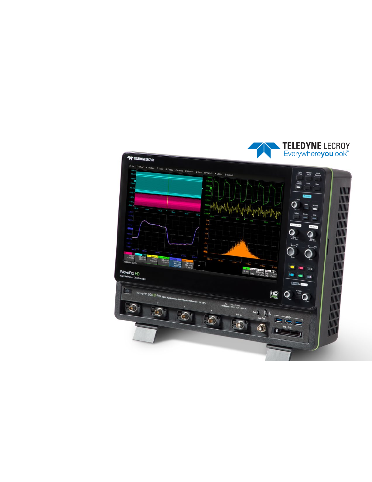
A. Touch Screen Display
B. Front Panel
C. Power On/Off Button
D. Calibration and Ground Terminals
E. USB 3.1 Ports (3)
F. Channel Inputs
G. Ext In
H. Aux Out
I. Mixed Signal Interface
J. Tilting Feet
Front of Oscilloscope
OVERVIEW
A
D
C
B
E
F
G H
I
J

WavePro HD Getting Started Guide
5
OVERVIEW
The touch screen display is the principal viewing and control center of
the oscilloscope. See p.10 for an overview of its components.
The front panel houses buttons and knobs that control different
oscilloscope settings. Operate the instrument using front panel controls,
touch screen controls, or a mix that is convenient for you.
Front mounted host USB 3.1 ports can be used for transferring data or
connecting peripherals such as a mouse or keyboard.
The mixed signal interface connects the digital leadset to input up-to-16
digital lines (on -MS models).
Calibration output terminal is used to compensate passive probes. The
Ground terminal may be connected to a grounding wrist strap or the
ground lead on probes.
Channels 1–4 are used to input analog signal. The connectors are
equipped with the new ProBus2 interface, compatible with either legacy
ProBus or new ProBus2 probes. They can also accept a conventional
BNC cable.
Note: The BNC inputs are rated to 8 GHz but will require a precision
adapter (available from Teledyne LeCroy Service) to accept SMA cables.
The tilting feet change the angle of display for easier viewing.
Powering On/Off
Connect the line cord rated for your country to the AC power inlet on the
back of the instrument, then plug it into a grounded AC power outlet. (See
Power in “Safety”).
The Power button controls the operational state of the oscilloscope.
Press Power to switch on the instrument and load the oscilloscope software.
The LED on the button lights to show the oscilloscope is on. Press it again to
switch “off” (Standby power).
CAUTION. Do not power on or calibrate the oscilloscope with a
signal attached.
Always use the Power button or the File > Shutdown menu option to
execute a proper shut down process and preserve settings.
The Power button does not disconnect the oscilloscope from the AC
power supply; some “housekeeping” circuitry continues to draw power.
The only way to fully power down the instrument is unplug the AC line
cord from the outlet.
CAUTION. Do not place the instrument so that it is difficult to reach
the power cord in case you need to disconnect from power.
We recommend unplugging the instrument if it will remain unused for a
long period of time.
929412-00 Rev A
6
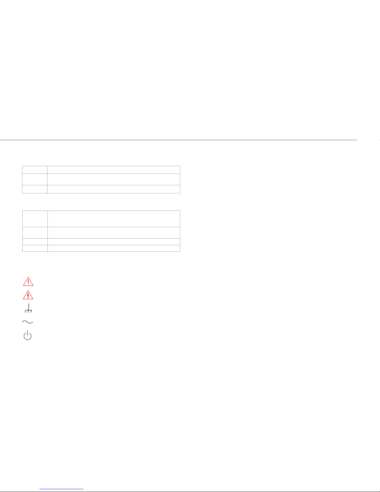
A. Built-in Carrying Handle
B. Removable Solid State Drive
C. AC Power Inlet
D. Kensington Lock
E. Ref In and Ref Out Connectors
F. USBTMC port for remote control
and data transfer
Back and Side of Oscilloscope
G. Speaker Out and Mic In
H. Ethernet Ports (2)
OVERVIEW
A
E
D
H
C
B
I
G
F
J
I. USB 3.1 Ports (4)
J. HDMI and DisplayPort Out
to external monitors

WavePro HD Getting Started Guide
7
OVERVIEW
Connecting to External Devices/Systems
After start up, configure external connections using the menu options
listed below. See the WavePro HD Oscilloscopes Operator’s Manual for
more detailed instructions.
Audio/USB Peripherals
Connect the device to the appropriate port. These connections are “plugand-play” and do not require any further configuration. Use the Windows
control panel to make adjustments. To go to the Windows desktop,
choose File > Minimize or swipe from the far left of the screen.
External Monitor
WavePro HD supports UHD monitors (up to 4096x2304 resolution).
Connect the monitor cable to the HDMI or DisplayPort output on the side
panel (you can use a convertor if the cable has a different interface). Go
to Display > Display Setup > Open Monitor Control Panel to configure
display settings. Be sure to select the instrument as the primary display.
To use the Extend Grids feature, configure the second monitor to extend,
not duplicate, the oscilloscope display. If the external monitor is touch
screen enabled, the MAUI user interface can be controlled through touch
on the external monitor.
LAN
WavePro HD is preset to accept DHCP network addressing over a
TCP/IP connection. Just connect an ENET cable from a port on the
side panel to a network access device. Go to Utilities > Utilities Setup >
Remote to find the IP address.
To configure a Static IP address, touch Net Connections on the Remote
dialog and enter the IP address.
Go to Utilities > Preference Setup > Email to configure email settings.
Printer
WavePro HD supports USB printers that are compatible with the Windows
OS installed on the oscilloscope. Connect the printer to any host USB
port, then go to File > Print Setup and select Printer to configure printer
settings. Touch Properties to open the Windows Print dialog.
Remote Control
You can control the instrument over a LAN using VICP (TCP/IP) or
VXI-11 (LXI). Use a standard ENET cable to connect to a network access
point, and be sure the instrument is on the same subnet as the controller.
To use LXI, switch to the Administrative User LCRYADMIN (p.40).
Note: You can also connect directly using TCP/IP, but depending on the
controller, you may need to use a cross-over cable.
USBTMC and GPIB (with the optional GPIB card) can also be used to
make a remote connection.
To change the remote control setting from the default VICP (TCP/IP), go
to Utilities > Utilities Setup > Remote.
Trigger Out
To send a trigger pulse to another device, connect a BNC cable from Aux
Out on the front of the instrument to the other device. Go to Utilities >
Utilities Setup > Aux Output and choose to output Trigger.
Reference Clock
To input or output a reference clock, connect a BNC cable from Ref In or
Ref Out to the other instrument. Go to Timebase > Horizontal Setup >
Clock Source to configure the clock.
929412-00 Rev A
8
OVERVIEW
Probes
WavePro HD oscilloscopes are compatible with the included passive
probes and most Teledyne LeCroy ProBus and ProBus2 active probes
that are rated for the oscilloscope’s bandwidth. Probe specifications and
documentation are available at teledynelecroy.com/probes.
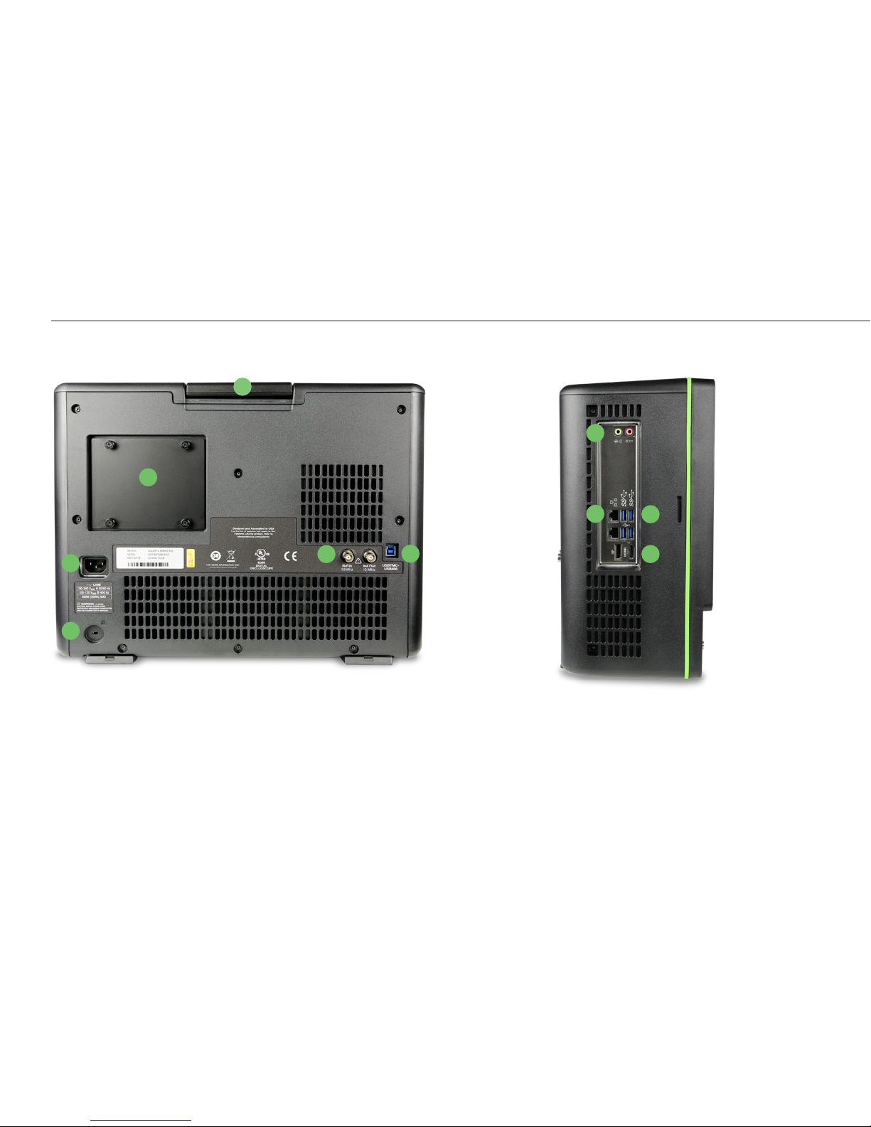
Digital Leadset
Delivered with the purchase of a Mixed Signal (-MS) model, the digital
leadset enables input of up-to-16 lines of digital data. Lines can be
organized into two logical groups representing different buses and
renamed appropriately.
The digital leadset features two digital banks with separate threshold and
hysteresis controls, making it possible to simultaneously view data from
different logic families.
Each flying lead has a signal and a ground connection. A variety of ground
extenders and flying ground leads are available for different probing
needs. To achieve optimal signal integrity, connect the ground at the tip
of the flying lead for each channel used in measurements. Use either the
provided ground extenders or ground flying leads to make the ground
connection.
To connect the leadset to the oscilloscope, push the connector into the
mixed signal interface below the front panel until you hear a click.
To remove the leadset, press in and hold the buttons on each side of the
connector, then pull out to release it.
WavePro HD Getting Started Guide
9
OVERVIEW
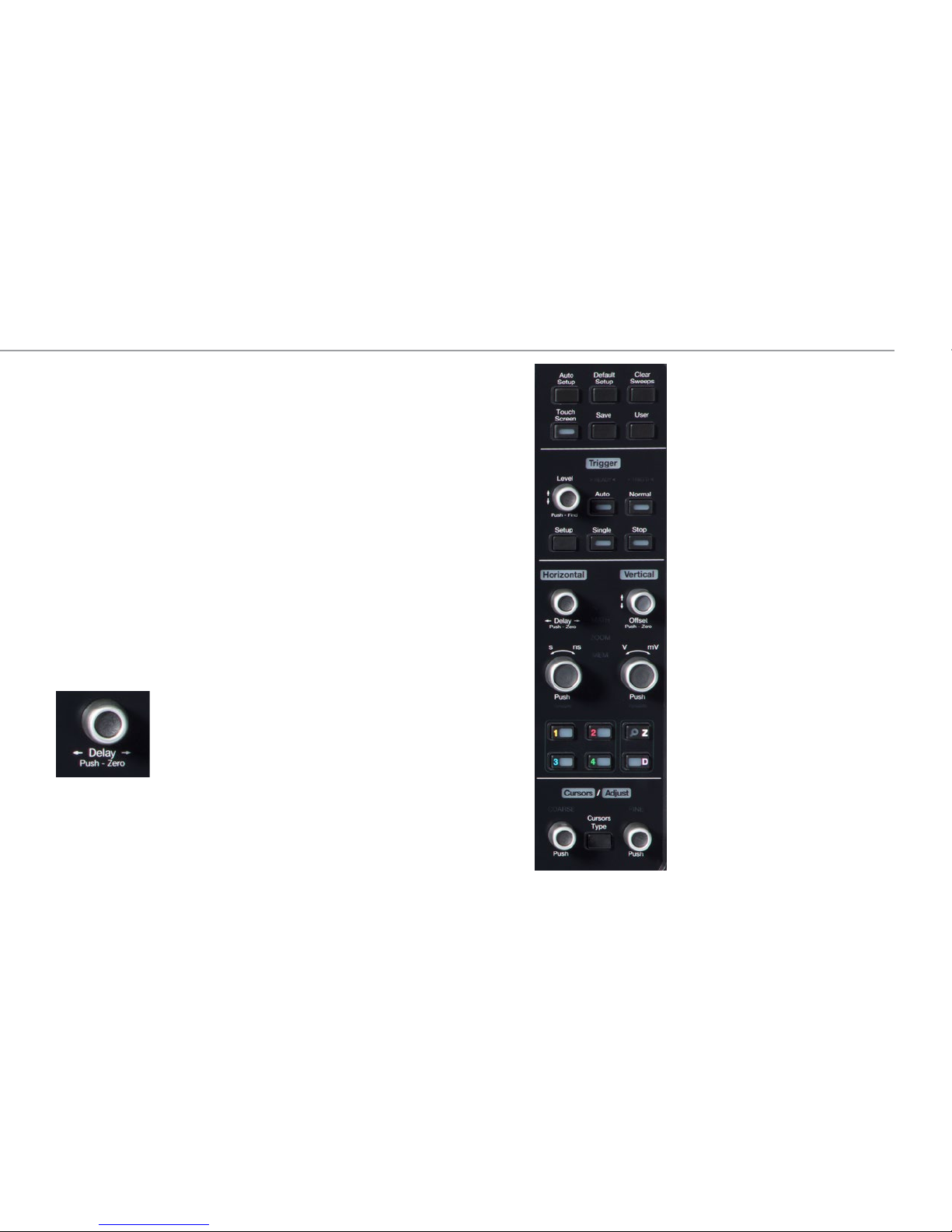
Front Panel
Most of the front panel controls duplicate functionality available through the
touch screen display. They are covered in more detail in the Basics section
and in the WavePro HD Oscilloscopes Operator’s Manual.
Shortcut buttons arranged across the top of the front panel give quick
access to commonly used functions.
The Touch Screen button enables or disables touch screen functionality.
The Save button performs the last action you set on the Save dialog: save a
setup file, waveform file, memory, screen image or LabNotebook.
The User button can be configured to perform your choice of functions: save
LabNotebook, waveform or setup files; save setups or waveforms to internal
memory; "print" the screen to a file or to hardcopy; find optimal Vertical Scale
for a selected channel, etc. See the Operator's Manual for instructions.
When cursors are turned off, the Cursor knobs act as the Adjust knobs.They
raise/lower the value when a data entry field is selected, or raise/lower trace
intensity when a waveform is selected. Pushing the Adjust knobs returns
settings to the default value.
All the knobs on the front panel function one way if
turned and another if pushed like a button. The first label
describes the knob’s principal “turn” action; the second
label describes its “push” action.
Many front panel buttons light to indicate which
functions and traces are active. The labels for Trigger,
Horizontal, Vertical and Cursors/Adjust also light in the
color of the trace that is currently associated with these
knobs.
929412-00 Rev A
10
OVERVIEW
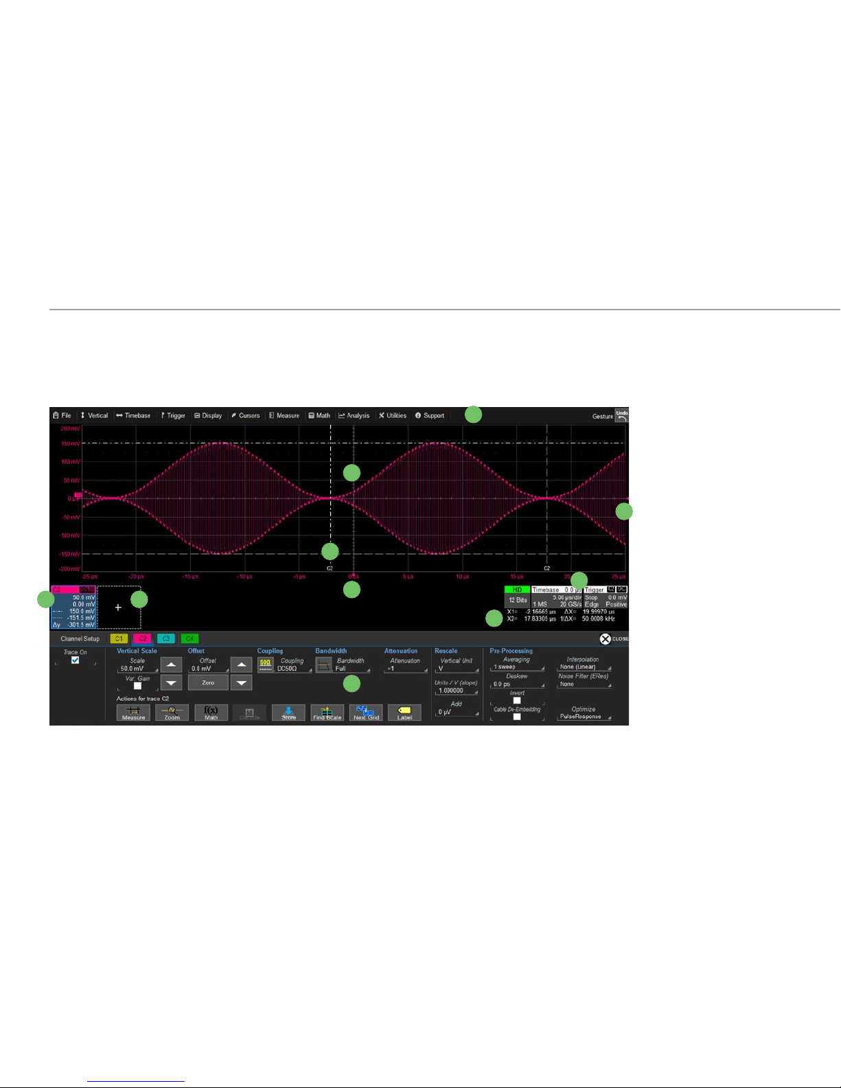
Touch Screen Display
The entire display is a capacitive touch screen. Use your finger or a capacitive stylus (not included) to touch, double-touch, touch-and-drag, or draw
a selection box. Many controls that display information also work as “buttons” to access other functions. If you have a mouse installed, you can click
anywhere you can touch to activate a control; in fact, you can alternate between clicking and touching, whichever is convenient.
A
E
D
H
C
B
I
G
F
J
A. Menu Bar
B. Grid Area
C. Trigger Level Indicator
D. Trigger Time Indicator
E. Trace Descriptor Boxes
F. Add New Box
G. Cursor Markers
H. Timebase and Trigger
Descriptor Boxes
I. Horizontal Cursor
Readout
J. Setup Dialogs
WavePro HD Getting Started Guide
11
OVERVIEW
A menu bar of drop-down menus lets you access all functionality.
If an action can be “undone” (such as recalling a setup), a small
Undo button appears at the far right of the menu bar. Click this
to return to the previous oscilloscope display.
The grid area displays the waveform traces. You can adjust the
brightness of the graticule, or change the number and style of grids.
Trigger level (vertical axis) and trigger time (horizontal axis) indicators
appear on the grid when a trigger is set, color-coded to match the source.
Cursors show where measurement points have been set. Touch-and-drag
cursor indicators to quickly reposition the measurement point. Vertical
cursor readout appears on the Channel descriptor box; Horizontal cursor
readout appears below the Timebase and Trigger descriptor boxes.
Trace descriptor boxes appear along the bottom of the grid area, one for
each open trace. They adjust in size and detail as more are opened.
The Add New box sits next to the trace descriptor boxes. Use it to turn on
new traces or the Measure table. See MAUI with OneTouch on p.15.
Timebase and Trigger descriptor boxes appear at the right of the display.
Timebase and Trigger settings only apply to channel traces. Touch the
descriptor box to open the corresponding set up dialog.
Dialogs appear at the bottom of the display for entering set up data. The
top dialog will be the main entry point for the selected function.
For convenience, related dialogs appear as a series of tabs behind the
main dialog. Touch the tab to open the dialog
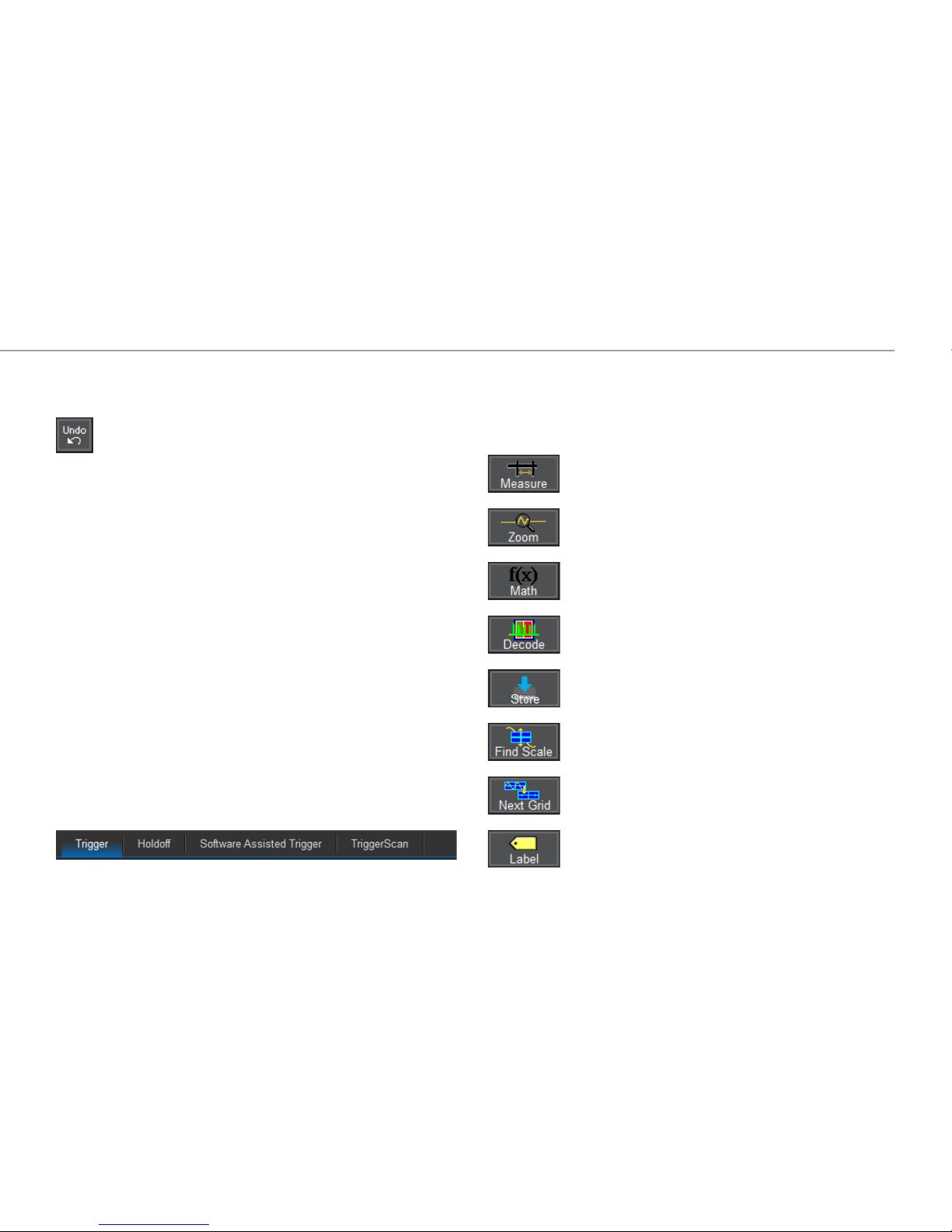
The Action toolbar on the main Channel, Math and Memory dialogs offers
shortcuts to common actions so you don’t have to leave the underlying
dialog. Actions always apply to the active (highlighted) trace.
Apply up-to-12 measurement parameters
Display a zoom of the trace
Apply a math function to the trace
Open the Serial Decode dialog (if decoders are installed)
Copy the active trace to the corresponding
internal memory (e.g., C2 to M2)
Scale the waveform to fit the grid
Move the active trace to the next grid
Apply a custom label to the trace
929412-00 Rev A
12
BASICS
Changing the Display
Grid Mode
The grid is 8 Vertical divisions representing 4096 Vertical levels and 10
Horizontal time divisions. The value represented by each division depends
on the scale settings of the traces that appear on it.
8 Vertical
Divisions
4096
Vertical
Levels
The grid area can contain multiple grids, each representing the full
number of Vertical levels, so vertical precision is always maintained.
4096
Vertical
Levels
4096
Vertical
Levels
By default, the oscilloscope has the Auto grid mode enabled. Auto adds a
grid for each new trace, up to 20 grids, until no more grids are available. Other
grid modes create a fixed number and orientation of grids; the icon shows
the result.
To modify the touch screen display, choose Display > Display Setup from the
menu bar and make your selections from the Display dialog.
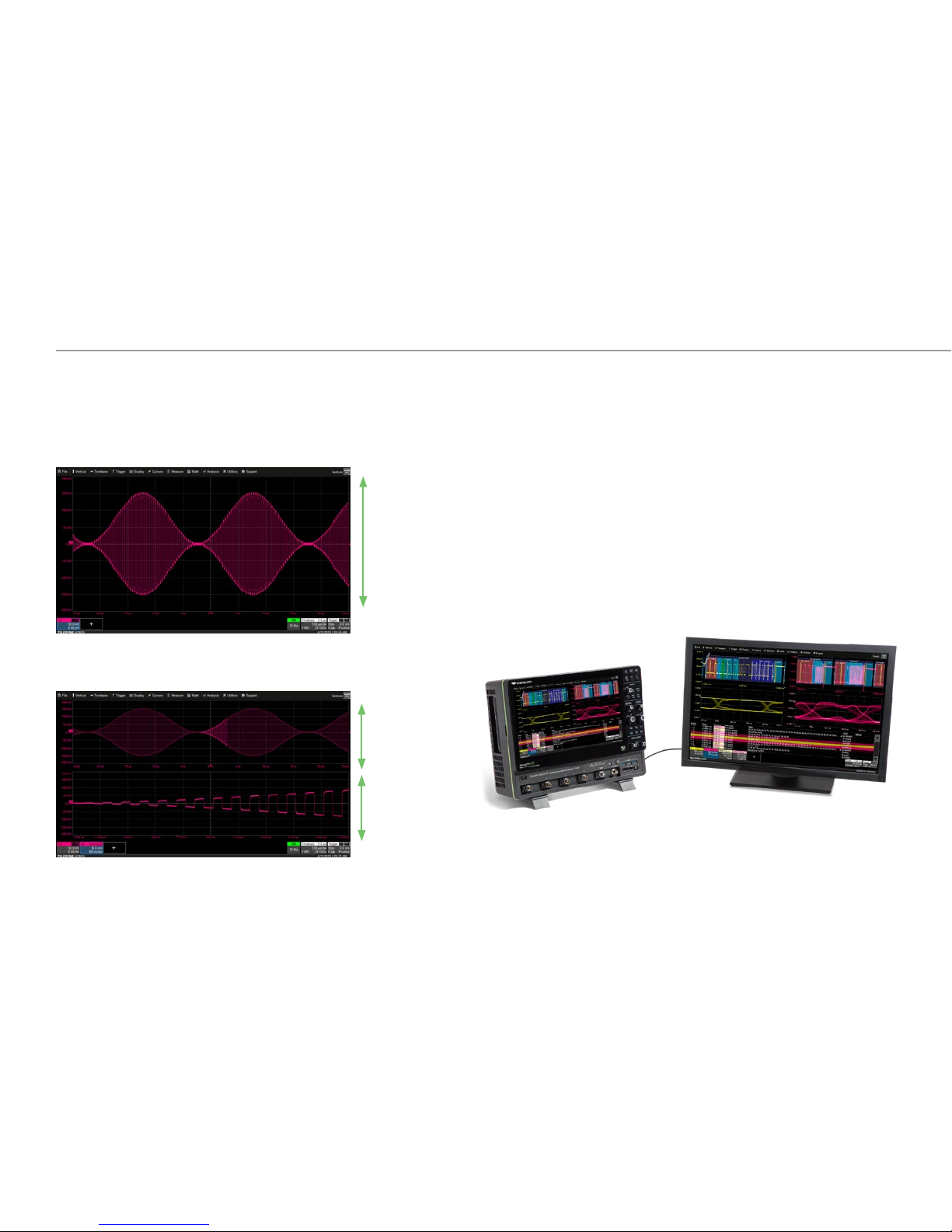
Extended Display
If you have a second monitor connected, select Extend Grids on 2nd
Monitor from the Display dialog, then choose a grid style from the Extended
Display pop-up menu. Both displays will share this grid style. Drag-and-drop
descriptor boxes to move traces between the displays.
Oscilloscope with an extended display.

WavePro HD Getting Started Guide
13
BASICS
With the trace selected (and cursors
off), turn the front panel Adjust knobs to
control the Trace Intensity.
Various types of Persistence can be
added to the display to visualize how
waveforms change over time. Persistence
displays can be colorized or modeled in
3D and rotated on three axes.
Line, Intensity, and Persistence
The trace style can be set to a series of separate sample Points or a
continuous vector Line.
Grid Intensity makes the graticule dimmer or brighter relative to the trace.
When more data is available than can actually be displayed, Trace Intensity
helps to visualize significant events by applying an algorithm that dims less
frequently occurring samples.
Intensity 100%
Intensity 15% Intensity 15% with Color Persistence
Intensity 15% with Analog Persistence
 Loading...