

Teledyne Lecroy WaveSurfer 4000HD Operator's Manual

Operator's Manual
WaveSurfer 4000HD
Oscilloscopes

Wa veSurfer 4 000HD OscilloscopesOperator'sManual
© 2019 Teledyne Le Croy,Inc. All rig hts reserved.
Una uthorized du plication of Tele dyne LeCroy ,Inc. documentation materials is s trictly prohi bited. Cli ents are
permitted to duplicate and di stribute Tel edyne LeCroy ,Inc. documentation for in ternal educational purposes.
Teledy ne LeCroy is a trademark of Teled yne LeCroy,I nc.,Inc. Other product or brand names are trademarks or
requeste d trademarks of their resp ective holders. I nformation in th is publication s upersedes a ll earlier versions.
Sp ecifications are s u b j e ct to change without notice.
November,2019
wavesurfer4000hd-om-eng_01nov19

Contents
OscilloscopeOverview andSet Up 1
Safety 1
Overview 4
PoweringOn/Off 10
SoftwareActivation 10
Language Selection 10
Connectingto OtherDevices/Systems 11
Configuringthe Save/User Button 12
UsingMAUI 13
Touch Screen 13
MAUIwith OneTouch 18
WorkingWith Traces 22
Zooming 25
Acquisition 29
Auto Setup 29
Vertical 30
Digital(MixedSignal) 33
Timebase 37
Trigger 43
Display 51
DisplaySet Up 51
PersistenceDisplay 52
Cursors 55
CursorTypes 55
Apply andPositionCursors 57
StandardCursorsDialog 58
XYCursorsDialog 58
Measure 59
MeasureTable 59
Parameter Set Up 60
List of StandardMeasurements 62
Using Trends 65
Math 67
Math Function Set Up 67
Math Dialog 68
List of StandardMathOperators 69
Average Function 71
i

WaveSurfer 4000HD Oscilloscopes Operator's Manual
EResFunction 72
FFTFunction 74
RescaleFunction 76
Memory 81
SavingMemories 81
RestoringMemories 82
AnalysisTools 83
WaveScan 83
PASS/FAIL Testing 87
SavingData(File Functions) 89
Save 89
Recall 95
LabNotebook 97
Share 99
Email Settings 99
Print 101
Using theFileBrowser 102
Utilities 105
UtilitiesDialog 105
Disk Utilities 110
PreferencesDialogs 111
WaveSourceAutomatic Waveform Generator 115
DigitalVoltmeter 117
Maintenance 119
Restore Default Setup 119
WaveSurfer Firmware Update 119
Technical Support 120
Returninga Product forService 121
Certifications 123
EMCCompliance 123
Safety Compliance 124
EnvironmentalCompliance 125
ISOCertification 125
IntellectualProperty 125
Warranty 126
Index 127
ii

Welcome
Thankyoufor purchasingaTeledyne LeCroyWaveSurfer 4000HDoscilloscope.We're certainyou'll be
pleased with thedetailedfeaturesunique to our instruments.
Takea moment to verify that allitems on thepackinglist or invoicecopyhavebeenshippedto you.
Contact yournearest Teledyne LeCroycustomerservice center or nationaldistributorif anythingis
missingor damaged. Wecanonlyberesponsible for replacement if youcontact usimmediately.
WetrulyhopeyouenjoyusingTeledyneLeCroy's fineproducts.
iii

WaveSurfer 4000HD Oscilloscopes Operator's Manual
iv
Oscilloscope Overview andSet Up
OscilloscopeOverview and Set Up
Safety
Symbols
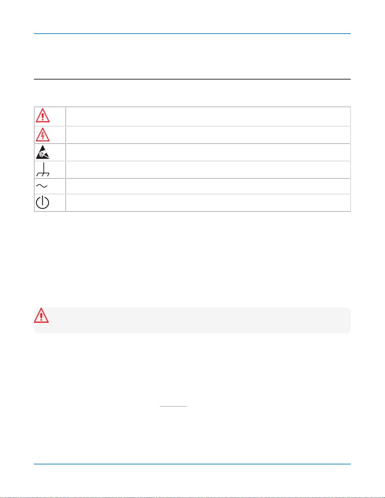
Thesesymbolsappearonthe instrument orindocumentationto alert youto important safety concerns:
Cautionof potentialdamageto instrument orWarningof potentialbodilyinjury.Refer to
manual.Donot proceeduntil theinformationisfullyunderstood andconditionsaremet.
Caution,highvoltage;riskof electric shockor burn.
Caution
Frame or chassis terminal(groundconnection).
Alternatingcurrent.
Standbypower (front of instrument).
,containsparts/assembliessusceptibletodamagebyElectrostatic Discharge(ESD).
Precautions
Observegenerallyaccepted safety proceduresinadditionto theprecautionslisted here.The overall
safetyofanysystem incorporatingthisproduct istheresponsibilityoftheassemblerof thesystem.
Useindoorsonly.
Useonlywithintheoperationalenvironment listed. Donot use inwet or explosiveatmospheres.
Maintainground. TheACinlet groundisconnecteddirectlyto the chassisof theinstrument. To avoid
electric shock,connect onlytoamatingoutlet with asafetygroundcontact.
Caution:Interruptingthe protectiveconductor insideor outsidetheoscilloscope,or disconnecting
thesafetygroundterminal,createsa hazardoussituation.Intentionalinterruptionis prohibited.
Connect anddisconnect properly.Donot connect/disconnect probes,test leads,or cableswhilethey are
connected to alivevoltagesource.
Observeallterminalratings. Donot applya voltage to anyinput that exceedsthemaximum ratingof that
input. Refer to thebodyof theinstrument for maximum input ratings.
Useonlythepowercordshippedwiththeinstrumentandcertifiedfor the country of use.
Keepproduct surfacescleananddry.SeeCleaning.
Donot removethecoversorinsideparts.Refer allmaintenancetoqualifiedservicepersonnel.
Exercisecarewhenlifting.Usethebuilt-in carryinghandle.
Donot operatewithsuspectedfailures.Donot usethe product if anypart isdamaged.Ceaseoperation
immediatelyand secure theinstrumentfrom inadvertent use.
1
WaveSurfer 4000HD Oscilloscopes Operator's Manual
Operating Environment
Temperature
Humidity
Altitude
: Maximum relativehumidity
: Upto 10,000 ft (3,048m) at or below30°C.
:
0 °Cto 50
decreasinglinearlyto 50%relativehumidity at 40 °C.
°C.
90%
upto 31 °C,
Measuring Terminal Ratings (C1-C4 and Ext)
MaximumInput Voltage:50 Ω coupling≤ 5Vrms
1MΩ coupling≤ 400 Vpkmax.(PeakAC≤ 10 kHz+DC)
deratingat 15dB/decadefrom 10 kHzto1.6MHz,
10 Vpkmax.above 1.6 MHz
Caution:Measuringterminalshavenoratedmeasurement categoryperIEC/EN61010-1:2010.
Measuringterminalsarenot intendedto beconnected directlytosupply mains.
Cooling
Theinstrument relieson forcedair coolingwithinternalfansandvents.Takecareto avoidrestricting the
airflow to anypart. In a benchtopconfiguration,leaveaminimum of 15 cm (6inches)aroundthesides
betweenthe instrument andthe nearest object. Thefeet provideadequate bottom clearance.Follow
rackmount instructionsfor properrack spacing.
Caution:Donot blockthe cooling vents.
Theinstrument alsohasinternalfancontrolcircuitry that regulatesthe fanspeedbasedontheambient
temperature.Thisisperformedautomaticallyafter start-up.
Cleaning
Cleanonlythe exteriorof the instrumentusinga soft cloth moistenedwith water or an isopropylalcohol
solution.Donot useharshchemicalsorabrasive elements.Under nocircumstancessubmergethe
instrument or allow moisturetopenetrateit. Drythoroughlybeforeconnectingalivevoltagesource.
Caution:Unplugthepower cordbefore cleaning. Donot attempt to cleaninternalparts.
2

Oscilloscope Overview andSet Up
Power
Theinstrument automaticallyadaptsto the linevoltage;manualvoltageselection isnot required.
ACPowerSource
MaximumConsumption
NominalConsumption
StandbyConsumption
* AllPCperipheralsandactiveprobesinstalledonfour channels.
Theprovidedpower cordsmate to acompatiblepower inlet on theinstrument for makinglinevoltage and
safetygroundconnections.TheACinlet groundisconnecteddirectlyto thechassisof theinstrument. For
adequate protection againelectric shock,connect to a mating outlet with a safety groundcontact.
: 100-240 VACat 50/60 Hz(±5%)
100-120 VACat 400 Hz(± 5%)
:*
:
:
150 W(150 VA)
90 W(90 VA)
4W
3
WaveSurfer 4000HD Oscilloscopes Operator's Manual
Overview
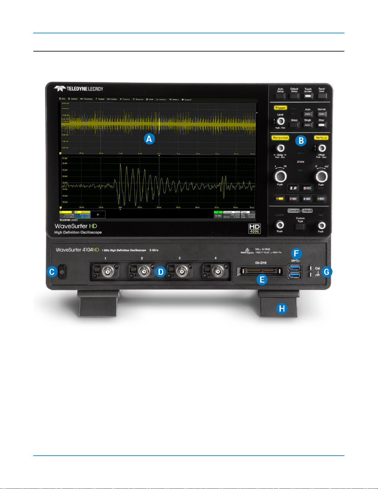
Front of Oscilloscope
A. Touch screen display
B. Front panelcontrols
C. StandbyPowerbutton
D. ProBusanaloginputs(4)
4
E. MixedSignalinterface
F. USB3.1Gen 1 ports(2)
G. GroundandCal Out terminals
H. Tiltingfeet

Back of Oscilloscope
Oscilloscope Overview andSet Up
A. Wave Sourceoutput
B. Kensington lock
C. Micro SDcard (removabledrive)
D. EXTtriggerinput
E. AUXoutput
F. HDMI out (toexternalmonitor)
G. Ethernet (LAN)port
H. USBTMCport
I. USB2.0 ports(2)
J. ACpower inlet
5
WaveSurfer 4000HD Oscilloscopes Operator's Manual
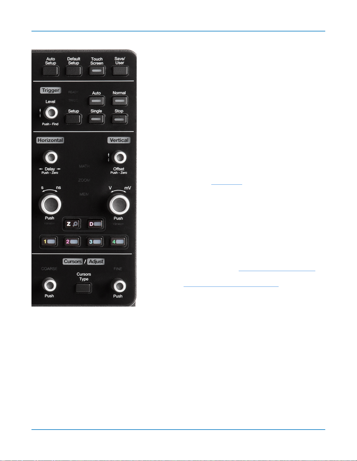
Front Panel
Front panelcontrolsduplicatefunctionality available throughthe
touch screen andare described hereonlybriefly.
Knobs onthefront panelfunctiononewayif turned andanother if
pushed likea button.Thefirst labeldescribesthe knob’s“turn”
action,the second labelits“push”action.Actionsperformedfrom
thefront panelalwaysapplyto the activetrace.
Many front panelbuttonslight toindicate which functionsand
tracesareactive.The labelsfor Trigger,Horizontal,Verticaland
Cursors/Adjust willlight inthecolorof thetracethat is currently
associatedwith theseknobs. The Math,Zoom,andMem
indicators betweenthe Horizontal andVerticalknobswilllight
whentheyare controllinga mathfunction,zoom,or memory
trace (instead of achannel).
MiscellaneousControls
AutoSetupperformsan Auto Setup.Afterthefirst press,youwill
bepromptedfor a confirmation.Pressthebutton againor usethe
touch screen toconfirm.
Default Setupresets theoscilloscopeto the factory default
configuration.Afterthefirst press,youwillbe prompted for a
confirmation.Press thebutton againor usethetouchscreento
confirm.
TouchScreentoggleson/off touch screen functionality.
Save/Usercan beconfiguredasyouchoose,forexample:savea
screencapture usingyourcurrent ScreenImage Preferences;
saveother filetypes;or clearsweepsandrestart measurement
counters.SeeConfiguringthe Save/ UserButton for instructions
onmakingthe selection.
TriggerControls
Thefront panelLevelknobchangesthe triggerthresholdlevel(Vor A). Thenumber isshown on the
Triggerdescriptor box.Pushing the knobsetsthe triggerlevel to the50%amplitude of theinput signal.
TheREADYindicator lightswhenthe triggerisarmed.The TRIG'D indicator lightswhena triggeroccurs.
SetupopenstheTriggerSetupdialog. Pressit againto closethedialog.
Autostarts Auto triggermode,whichtriggerstheoscilloscopeafter a set time,evenif thetrigger
conditionsarenot met.
Normalstarts Normal triggermode,which triggersthe oscilloscopeeachtime thesignal on thetriggering
channelmeetsthe triggerconditions.
6

Oscilloscope Overview andSet Up
Single startsSingletriggermode(single-shot acquisition).The first pressarms theoscilloscopetotrigger.
Thesecondpresstriggerstheoscilloscopeoncewhenthetriggeringsignalmeets the triggerconditions.
Stoppreventsthescopefrom triggeringon a signal. If youboot up theinstrument with the triggerin Stop
mode,a "Notrace available"message is shown.Select another modeto beginacquisition.
HorizontalControls
Turnthe Delayknobtoraise/lowertheTriggerDelayvalue(S).Pushtheknobtoreset Delaytozero.
If thetracesourceisan input channel,turntheHorizontalAdjust knobtoset theTime/division (S)of the
oscilloscopeacquisitionsystem. Thevalueisshown ontheTimebasedescriptorbox.Whenusingthis
control,theoscilloscopeallocatesmemoryasneededto maintain thehighest sample ratepossiblefor the
timebasesetting.If theactivetrace isa math,zoom or memory,usethisknobtochangetheHorizontal
Scale,effectively"zooming"inor out. The valueisshown on thecorrespondingdescriptor box.
Push theknobto adjustscaleinfineincrements;pushit againto return tosteppedincrements.
VerticalControls
TheOffset knobadjusts thezerolevelof thetrace (thismakesit appeartomoveupor downrelativeto the
center axisof thegrid).The valueappearson thetrace descriptorbox.Pushit to reset Offset to zero.
TheVerticalAdjust knobsets Volts/divforchanneltracesor VerticalScalefor math,zoom and memory
traces.Thevalueappearson the trace descriptor box.Pushtheknobto togglebetweenfineandstepped
increments.
TheChannelbuttons(1-4)turn on achannelthat isoff,or activate achannelthat isalreadyon. Whenthe
channelis active,pushingitschannelbuttonturns it off. Alit buttonshowstheactivechannel.
TheZoom (Z) buttoncreates aQuick Zoom of each opentrace.Theresultingzoom tracesare 1/10 of the
sourcechannelscaleand centered onthe display. Usethe Horizontal knobsto adjustthis,or touch the
zoom descriptor box twiceto displaythezoomdialogcontrols.Touchthe Zoom button againto turn off
thezooms.
TheDigital(D) buttonenablesdigitalinput onoscilloscopeswith the MSOoption.
CursorControls
Cursorsidentifyspecific verticalandhorizontalvalues on thewaveform. Thewhitecursor markershelp
make thesepoints morevisible,aswellasprovideasimplewayto repositionthem. Areadout of the
verticalvaluesappearson thetrace descriptorbox,whilethe horizontalvalues appearbelowthe
Timebasedescriptor box.
Thereare fivepreset cursor types,each with a uniqueappearanceonthe display. Thesearedescribedin
more detailin theCursorssection.
Press theCursorType button to applyor removecursors.Continuepressingtocyclethroughallcursor
typesuntil thedesiredtypeisfound("Off"occurswhenno cursorsare visible).
Turnthe Coarseknobto adjust the positionof absolute cursors(dashed-dotted lines).Pushit toreturn the
cursor tothedefault 2.5 division setting. If you're usingthe Both Relcursortype,eachpushwillselect the
other absolute cursor.With thecorrect cursor selected(highlighted),turnthe knobto adjust the position.
7

WaveSurfer 4000HD Oscilloscopes Operator's Manual
Turnthe Fineknobto adjust thepositionof relativecursors(dashedlines).Pushit to return thecursor to
thedefault 7.5 division setting,or toselect the otherrelativecursor when usingtheBoth Relcursortype.
When Cursorsareoff and a dataentry fieldisselected,theseknobsserveastheAdjust knobs.Turnthe
left knobto makecoarse(1-,2-,5-,10-stepped)adjustments;turnthe right knobto makefine(singleincrement) adjustments.Pusheither knobtoreturn to thedefault setting.
Signal Interfaces
Teledyne LeCroyinstruments offeravarietyof interfacestoinput analogor digitalsignals. Seethe
oscilloscopeproduct pageat teledynelecroy.com foralist of compatibleinput devices.
ProBusInterface
Channelinputs C1-C4 utilizetheProBusinterface. The ProBusinterfacecontainsa 6-pinpower and
communicationconnectionand aBNCsignal connectionto the probe,with senseringsfor detecting
passiveprobes.It offersboth 50 Ω and 1 MΩ input impedance andprovides probepowerandcontrolfor a
widerangeof probessuch as highimpedancepassiveprobes,highimpedanceactiveprobes,current
probes,highvoltage probes,anddifferentialprobes.
TheProBus interface completelyintegratestheprobe with thechannel.Uponconnectinga Teledyne
LeCroyprobe,theprobe typeis recognizedand some setup information,suchasinput couplingand
attenuation,isperformedautomatically.Thisinformation isdisplayed on the ProbeDialog,behindthe
Channel(Cn) dialog.System (probe plusinstrument)gainsettingsareautomaticallycalculated and
displayedbasedonthe probeattenuation.
TheProBus interface mayhaveaBNC-terminated cableconnecteddirectlyto it.Dependingonthe BNC
connector usedonthe cable,theinterface isratedfor up to 4 GHzwith50 Ω coupling or 1 GHz with1MΩ
coupling.
Note:Operationalbandwidth isequaltothemaximum input frequency of youroscilloscopemodel.
See the product datasheet.
OtherAnalogInputs
EXTIncanbe usedto input anexternaltrigger pulse.
Thisinput hasasimpleBNCinterface with no power supply. Seeyour product datasheetforvoltageand
frequencyratings.
MixedSignalInputs
Thedigitalleadset shippedwiththeMSOoptionconnectsto the MixedSignal Input onthe front of the
oscilloscopetoinput of up-to-16linesof digitaldata. Physicallinescanbepreconfiguredinto different
logicalgroups,Digitaln,corresponding to a busand renamed appropriatelydependingonthegroup. The
transitionsfor each linemaybeviewed throughdifferent displays.
See DigitalSetupUsingthe DigitalLeadset for detailedinstructions.
8
Oscilloscope Overview andSet Up
Probes
Theoscilloscopeis compatiblewith theincludedpassive probesandmost Teledyne LeCroyactiveprobes
that are ratedfortheinstrument’sbandwidth.Probespecificationsand documentation areavailableat
teledynelecroy.com/probes.
PassiveProbes
Thepassiveprobessupplied are matched to theinput impedance of theinstrument but mayneed further
compensation.Follow thedirectionsinthe probeinstruction manualtocompensate thefrequency
response of theprobes.
If using other passive probesthan thosesupplied,be suretoperform a low frequencycalibration before
usingthem to measuresignal. Youcan usethe signalfrom the Cal Out hookonthe front of the
oscilloscope.
ActiveProbes
Teledyne LeCroyoffers a variety of activeprobesforusewith youroscilloscope.Most activeprobes
matchprobeto oscilloscoperesponseautomaticallyusingproberesponsedata storedinan on-board
EEPROM. Thisensuresthebest possible combinedprobe plusoscilloscopechannelfrequencyresponse
without the needto perform anyde-embedding procedure.
Beaware that manyactiveprobesrequirea minimum oscilloscopefirmwareversion to befully
operational.Seetheprobedocumentation.
Micro SDCard
TheMicroSDCard actsastheoscilloscope'sremovablehard drive.Useit to store and easilyshare setup
files,waveform files,LabNotebooks,andother userdata.
Toremovethecard,pushin andrelease. The cardshouldpartiallypopout,at whichpoint it can bepulled
out fully.
Toreplacethe card,pushit into the slot untilyouhearit click.
Note:WhenusingtheoscilloscopeDiskUtilities,theMicroSDcardislabeledStorageCard,whilea
connected USBdriveislabeled USBDisk.
9
WaveSurfer 4000HD Oscilloscopes Operator's Manual
Powering On/Off
Press thePowerbuttonto turn on theinstrument. The X-Stream applicationloadsautomatically
whenyouusethe Powerbutton.
Thesafest wayto power down the oscilloscopeistousetheFile >Shutdownmenuoption,which will
alwaysexecuteapropershut downprocessand preservesettings.QuicklypressingthePower button
should alsoexecute a propershut down,but holding the Powerbutton willexecute a “hard”shut down (as
ona computer),which we do not recommenddoingbecauseit doesnot allowtheoperatingsystem to
closeproperly,and setup datamay be lost. Neverpower off bypullingthe power cordfrom the socket,or
bypoweringoff aconnected power stripor batterywithout first shuttingdownproperly.
ThePower button doesnot disconnect the instrument from the ACpowersupply. The onlyway to fully
powerdowntheinstrument isto unplugthe ACpower cord.
Werecommendunpluggingtheinstrument if it willremainunused for a longperiodof time.
Caution:Donot poweronor calibrate with a signalattached.
Software Activation
Theoscilloscopesoftware (firmware andstandardapplications)isactiveupon delivery.At power-up,the
instrument loadsthe softwareautomatically.
Freefirmware updates are available periodicallyfrom the TeledyneLeCroywebsiteat:
teledynelecroy.com/support/softwaredownload
Registereduserscanreceivean emailnotification when a new update isreleased.Follow theinstructions
inFirmware Update to downloadandinstallthe software.
If youdecide topurchasean option,youwillreceivea licensekeyviaemailthat activates theoptional
features.See Optionsfor instructionsonactivatingoptionalsoftware packages.
Language Selection
Tochangethe languageof theoscilloscopeapplication:
1. GotoUtilities> PreferenceSetup>PreferencesandmakeaLanguage selection.
2. Follow theprompt torestart the application.
10
Oscilloscope Overview andSet Up
Connecting to Other Devices/Systems
Afterstart up,configuretheoscilloscopeconnectionsusingthe menuoptionslisted below.
LAN
Theoscilloscopeis preset to accept DHCPnetworkaddressing over a TCPIPconnection.Connect an
Ethernet cablefrom theport on theback panelto anetworkaccessdevice.
Go toUtilities> UtilitiesSetup> Remote to findthe IPAddress.
Toconfigurea Static IPaddress:
1. TouchNetConnectionson the Remotedialog.
2. Touchthe Mini-porticon(right) to open thedriversettings.
3. Select SpecifyanIPaddressandenter thenew address.
ToconfigureEmail,go to File > File Sharing> EmailSettings.
Remote Control
You can remote controlthe instrument usingTCP/IPoverLAN. Besuretheinstrument ison the same
subnet asthe controller.
Note:YoucanalsousetheLANport to makea direct connection,but depending on thecontroller,
youmayhavetousea cross-overcable.
TheWaveSurfer alsosupports remote controlviaUSBTMC orGPIB(withtheoptionalUSB-GPIBadapter).
Tochangethe remotecontrolsettingfrom the default TCP/IP,go to Utilities>UtilitiesSetup>Remote.
USB Peripherals
Connect peripherals(e.g.,mouse,keyboard)toany USBhost portonthefront or backof the instrument.
Theseconnectionsare"plug-and-play"anddo not requirefurther configuration.
External Monitor
WaveSurfer 4000HDsupports externalmonitors with 1280x800 ppi resolution.Connect themonitorcable
tothe HDMI videooutput on thebackof theinstrument. Theconnectionis“plug-and-play”and doesnot
requireanyfurther configuration.
Printer
WaveSurfer 4000HDsupports PictBridge-compliant printers.Connect theprinter to anyhost USBport. Go
toFile> Print Setupto configureprinter settings.
11

WaveSurfer 4000HD Oscilloscopes Operator's Manual
Trigger Out
Tosendatriggerout pulseto another device,connect aBNCcablefrom AuxOut onthebackof he
instrument to theother device.
WaveSource Waveform Generator
Connect a BNCcablefrom the WaveSource Output onthebackof the instrument tothe signalinput
device. Goto Utilities>WaveSourceto configurethe signal.
Note:WaveSource isoptionalandrequiresanactivated licensekey.
Configuring the Save/User Button
Thefront panelSave/Userbuttoncanbeconfiguredto perform your choiceof actions,such assaving a
screenimageor otherfiletype.
1. GotoUtilities> Front PanelSetup,then touch Select UserActionandmakeyourUser button
selection.
2. Optionally,touch Configure Actionto makeanyother settingrelated to that action,suchasScreen
Image or Print preferences.
12
Using MAUI
Using MAUI
MAUI(Most AdvancedUserInterface) isTeledyneLeCroy's uniqueoscilloscopeuser interface.
Touch Screen
Theoscilloscopefeaturesacapacitivetouchscreenthat supports fluid,tablet-like responsetogestures.
Note:Useyourfinger or a capacitivestylus(not included)tointeract withthetouchscreen.A
regularstyluswillnot work.
Theentire display areaisactive.Manycontrolsthat display informationalsoworkas“buttons”to access
other functions,and eventhe waveform tracescan bemanipulated.If youhavea mouseinstalled,you can
click anywhereyoucantouchtoactivate a control;infact,youcan alternatebetweenclickingand
touching,whicheverisconvenientforyou.
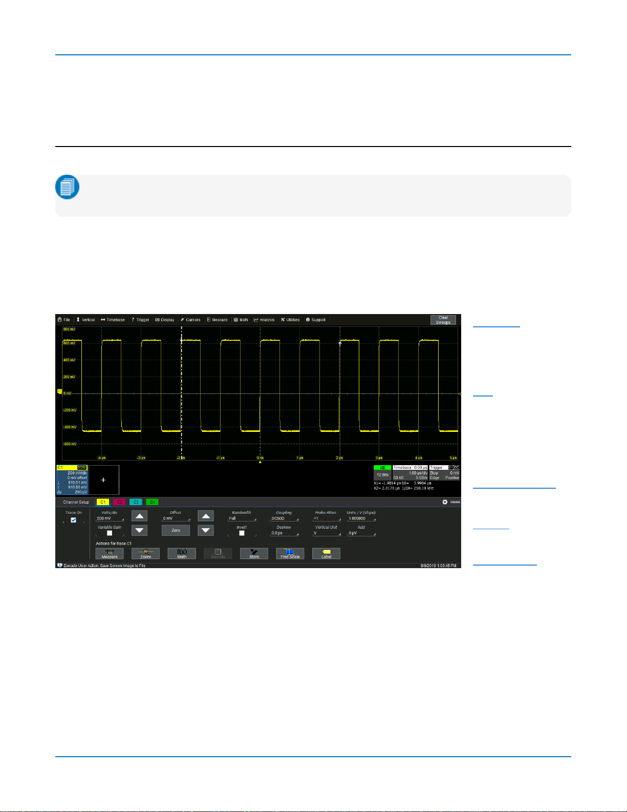
Thetouchscreenisdividedinto the followingmajorcontrolgroups:
Menu bar
Grid
Descriptorboxes
Dialogs
Messagebar
Menu Bar
Thetop of thewindow containsa completemenuof functions.Makinga selectionhere changesthe
dialogs displayedat thebottom of thescreen.Whilemanyoperationscan alsobe performedfrom the
front panelorlaunchedviathe descriptorboxes,the menubaris thebest way toaccessdialogsfor
Save/Recall(File)functions,Display functions,Status,LabNotebook,Pass/Failsetup,optionalAnalysis
packages,andUtilities/Preferences setup.
TheClearSweepsbuttonto theright of themenu bar clearsacquiredwaveformsfrom the history buffer
andresetsall measurement counters andhisticons.
13
WaveSurfer 4000HD Oscilloscopes Operator's Manual
Grids
Thegridsdisplay thewaveform traces.Everygridis8verticaldivisions representingthe fullnumber of
verticallevelsand10 horizontaldivisions.The valuerepresented byeach divisiondependson the Vertical
andHorizontalScaleof the tracesthat appearon thegrid.
Thegrid regioncan bedivided uptothree timesto show channel(Cn),math (Fn),and zoom (Zn) traceson
different grids.In AutoGrid mode,it willdivide automaticallyasneededwhennew typesof tracesare
turnedon. Two additionalgrid stylesallowyoutodisplayXYtraces,as wellasvoltage-time traceson
separategrids.Regardlessof the number and orientationof grids,everygridalwaysrepresents the same
number of Vertical levels. Therefore,absolute Verticalmeasurement precisionismaintained.
GridIntensity
You can adjustthebrightnessof thegrid linesbygoingtoDisplay>DisplaySetupandenteringanewGrid
Intensitypercentage.Thehigherthenumber,thebrighterandbolderthe grid lines.
GridIndicators
Theseindicatorsappeararoundor on thegridto markimportant pointson thedisplay. Theyare matched
tothe colorof the traceto which theyapply.Whenmultipletracesappearon thesamegrid,indicators
refer tothe foregroundtrace—theonethat appearsontopof the others.
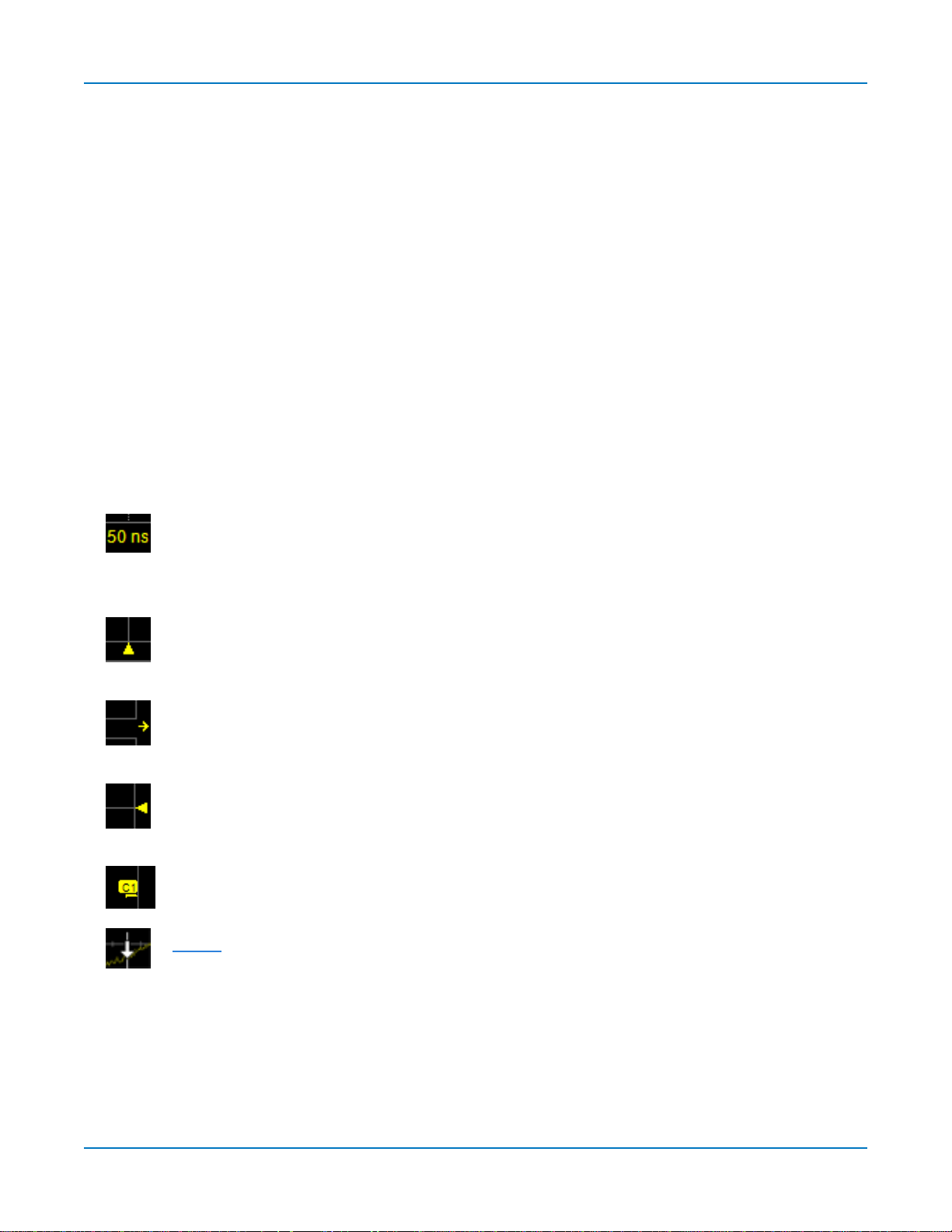
Axislabels
asyoupanthe trace or changethe scale. Originallyshown in absolute values,thelabels
showdeltafrom 0 (center) when thenumber of significant digitsgrowstoo large.To
removethem,go toDisplay>Display Setupanddeselect Axis Labels.
Trigger Time
time of thetrigger.Unless Horizontal Delayis set,thisindicator isat the zero(center) point
of the grid.Delay time is shownat the topright of the Timebasedescriptor box.
Pre/Post-triggerDelay
pre-orpost-triggerDelay hasshifted the TriggerTime indicatorto a timenot shown onthe
grid.AllDelayvaluesare shownonthe TimebaseDescriptor Box.
Trigger Level
changethe level,a hollowtriangleof the same colorappearsat the new leveluntilit has
triggered.Thetriggerlevelindicatorisnot shownif the triggeringchannelisnot displayed.
ZeroVoltsLevel
thegrid,sharingthenumber andcolorof thetrace.
Cursormarkers
thewaveform.Drag-and-drop cursormarkersto quicklyreposition them.
mark thetime andunit represented byagrid division.Theyupdatedynamically
,asmalltrianglealongthebottom (horizontal) edgeof the grid,shows the
,asmallarrow tothebottom left or right of thegrid,indicatesthat a
at the right edgeof thegridtracksthe last triggeredvoltagelevel.If you
islocated at theleft edgeof the grid.Oneappearsforeach opentrace on
appearoverthe grid toindicate the voltageandtimebeingmeasuredon
14
Using MAUI
Descriptor Boxes
Trace descriptor boxesappearjust beneaththe grid whenevera traceisturnedon.They functionto:
l Inform—descriptors summarizethe current trace settingsand itsactivitystatus.
l Navigate—touch thedescriptor box once to activate the trace,twice to openthe setup dialog.
l Configure—drag-and-dropdescriptor boxestochangesourceorcopy setups(with OneTouch).
Besidestrace descriptor boxes,there arealsoTimebaseandTrigger descriptor boxessummarizing the
acquisitionsettingssharedbyallchannels,which alsoopenthe corresponding setupdialogs.
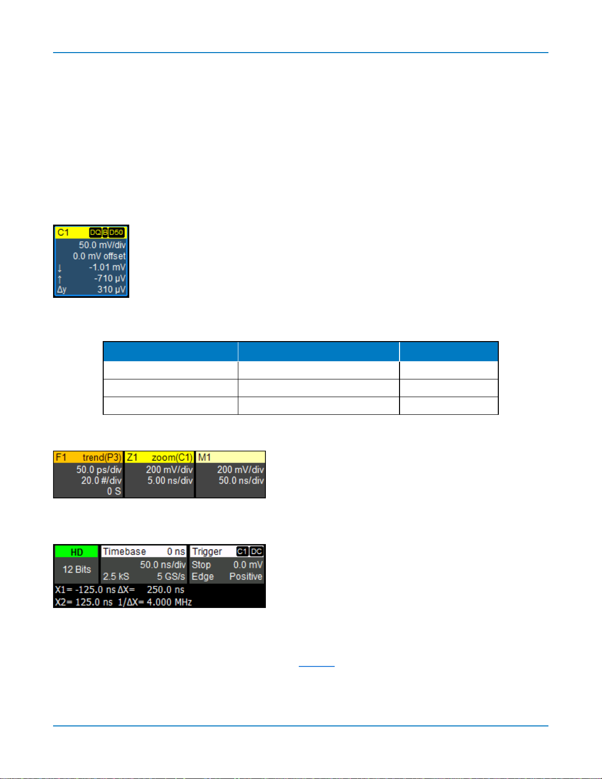
ChannelDescriptorBox
Channeltrace descriptor boxescorrespondtoanalog signalinputs. Theyshow
(clockwisefrom topleft):ChannelNumber,Pre-processinglist,Coupling,VerticalScale
(gain)setting,Vertical Offset setting,SweepsCount (whenaveraging),VerticalCursor
positions,and Number of Segments (inSequencemode).
Codesare usedto indicatepre-processing and coupling that hasbeenappliedto the
input. Theshort form isusedwhenseveralprocessesare in effect.
SymbolsonDescriptorBoxes
Pre-Processing Type Long Form Short Form
Deskew DSQ DQ
Bandwidth Limiting BWL B
Coupling DC50, DC1M, AC1M or GND D50, D1, A1 or G
OtherTraceDescriptorBoxes
Similardescriptor boxesappearformath (Fn),zoom (Zn),
andmemory(Mn) traces.Thesedescriptor boxesshow
anyHorizontal scalingthat differs from thesignal
timebase.Unitswillbe automaticallyadjusted for thetype
of trace.
TimebaseandTriggerDescriptorBoxes
TheTimebasedescriptor boxshows:(clockwisefrom top
right) HorizontalDelay,Time/div,SampleRate,Numberof
Samples,and SamplingMode(blankwhenin Real-time
mode).
Triggerdescriptor boxshows:(clockwisefrom topright)
TriggerSource andCoupling,Trigger Level(V),Slope/Polarity,TriggerType,TriggerMode.
Horizontal(time) cursorreadout,includingthetime betweencursorsandthe frequency,isshownbeneath
theTimeBase andTriggerdescriptor boxes.SeetheCursorssectionformore information.
15
WaveSurfer 4000HD Oscilloscopes Operator's Manual
Dialogs
Dialogsappearat thebottom of thedisplayfor entering setup data.Thetop dialogwillbethe mainentry
point for theselectedfunctionality.Forconvenience,related dialogsappear asaseriesof tabsbehindthe
main dialog.Touch thetabto openthedialog.
Right-HandSubdialogs
At times,yourselectionswillrequiremore settingsthan canfit on onedialog,or the taskinvitesfurther
action,suchaszoominganewtrace. In that case,subdialogswillappeartothe right of thedialog.These
subdialogsettingsalwaysapplyto the object that is beingconfiguredonthe left-handdialog.
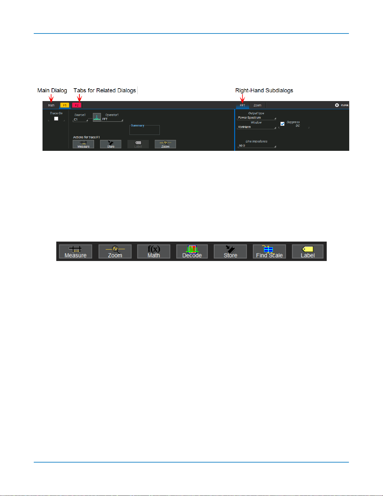
ActionToolbar
Severalsetup dialogscontaina toolbarat the bottom of thedialog. Thesebuttonsenableyouto perform
commonplacetasks—suchasturningon a measurement—without havingto leavetheunderlying dialog.
Toolbaractionsalwaysapplytotheactivetrace.
Measureopensthe Measurepop-up to set measurement parametersonthe activetrace.
Zoomcreatesazoom trace of theactivetrace.
MathopenstheMathpop-up toapplymath functionstothe activetrace and create a new math trace.
Decodeopensthe mainSerialDecodedialogwhereyouconfigureandapplyserialdata decodersand
triggers.Thisbuttonisonlyactiveif you haveserialdatasoftware optionsinstalled.
Storeloadstheactivetrace into the corresponding memory location(C1,F1andZ1 to M1;C2,F2andZ2
toM2,etc.).
FindScale performs a verticalscalingthat fits thewaveform intothegrid.
Labelopensthe Labelpop-up to annotate the activetrace.
16
Using MAUI
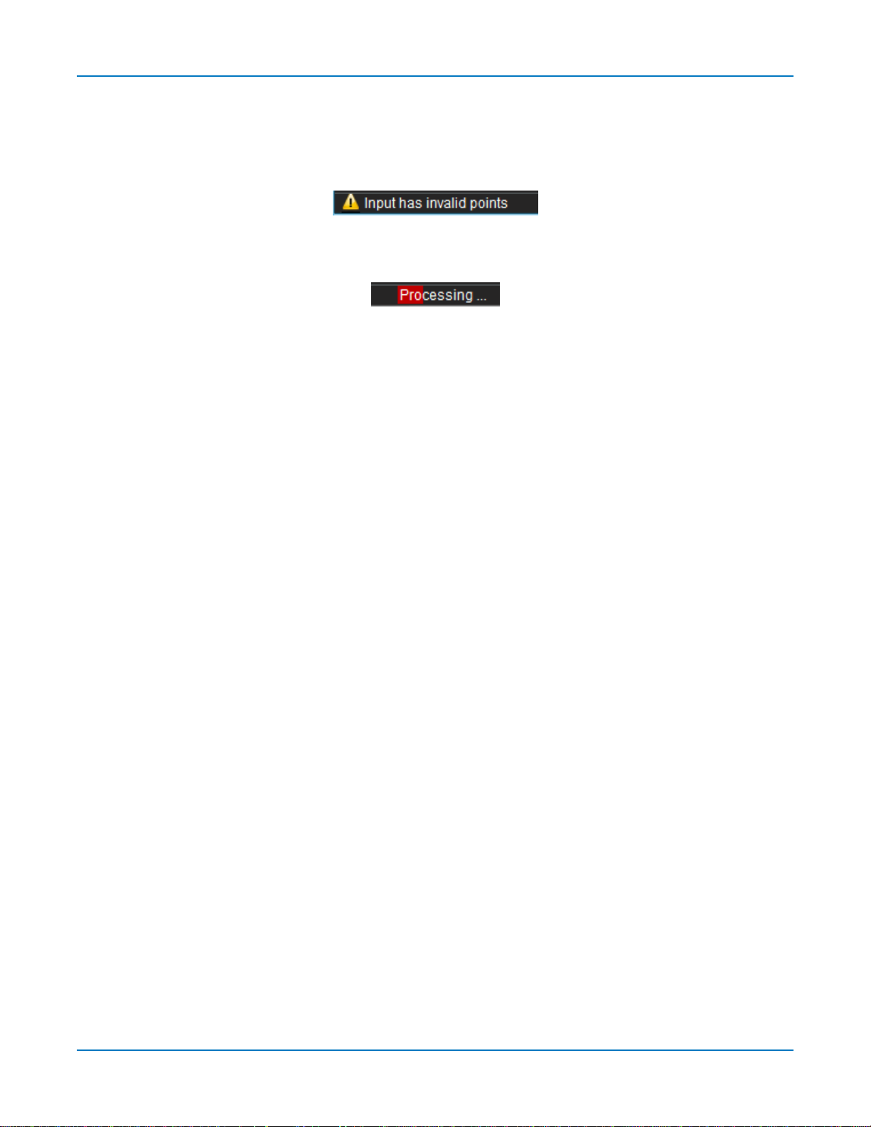
Message Bar
At thebottom of theoscilloscopedisplayisa narrow messagebar. Thecurrent dateandtimeareshown
at the far right.Status,error,or othermessagesareshownat the far left,where"TeledyneLeCroy"
normallyappears.
You willseethe word"Processing..."highlighted with redat theright of themessagebar when the
oscilloscopeisprocessing yourlast acquisitionorcalculating.
Thiswillbeespeciallyevident when youchangean acquisitionsettingthat affects theADCconfiguration
whilein NormalorAutotriggermode,suchaschangingtheVerticalScale,Offset,or Bandwidth. Traces
may briefly disappearfrom the display whiletheoscilloscopeisprocessing.
17
WaveSurfer 4000HD Oscilloscopes Operator's Manual
MAUI with OneTouch
Gestures liketouch,drag andswipecanbeusedto createandchangesetupswith onetouch. Just asyou
changethe displaybyusingthe setup dialogs,youcanchangethe setupsbymovingdifferent display
objects. Usethe setup dialogstorefine OneTouch actionstoprecisevalues.
Asyou drag&dropobjects,validtargetsare outlinedwith awhitebox.Whenyou're movingoverinvalid
targets,you'llseethe "Null"symbol( Ø) under yourfingertipor cursor.
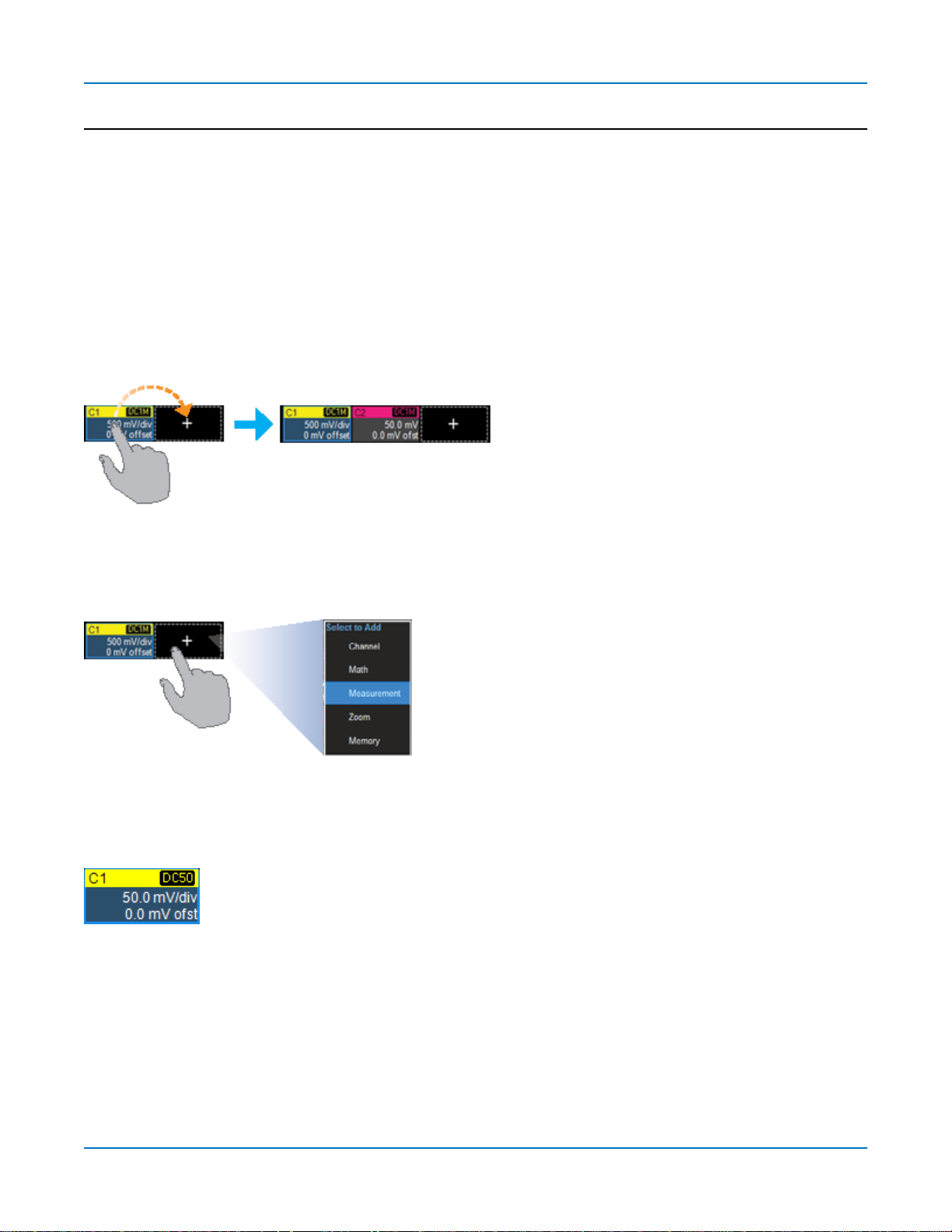
Turn On
Toturnona newchannel,math,memory,orzoom trace,draganydescriptorboxof thesame typeto the
Add New ("+")box.Thenext trace in theserieswillbe addedto thedisplay at thedefault settings.It isnow
theactivetrace.
If thereisnodescriptor boxof the desiredtypeon the screen todrag,touchthe AddNew boxand choose
thetracetypefrom thepop-up menu.
ToturnontheMeasure table when it isclosed,touch theAdd New boxandchooseMeasurement.
Activate
Touch a trace or itsdescriptor boxtoactivateit and bringit to theforeground.When the descriptor box
appearshighlightedinblue,front panelcontrolsand touch screen gestures applytothat trace.
18
Using MAUI
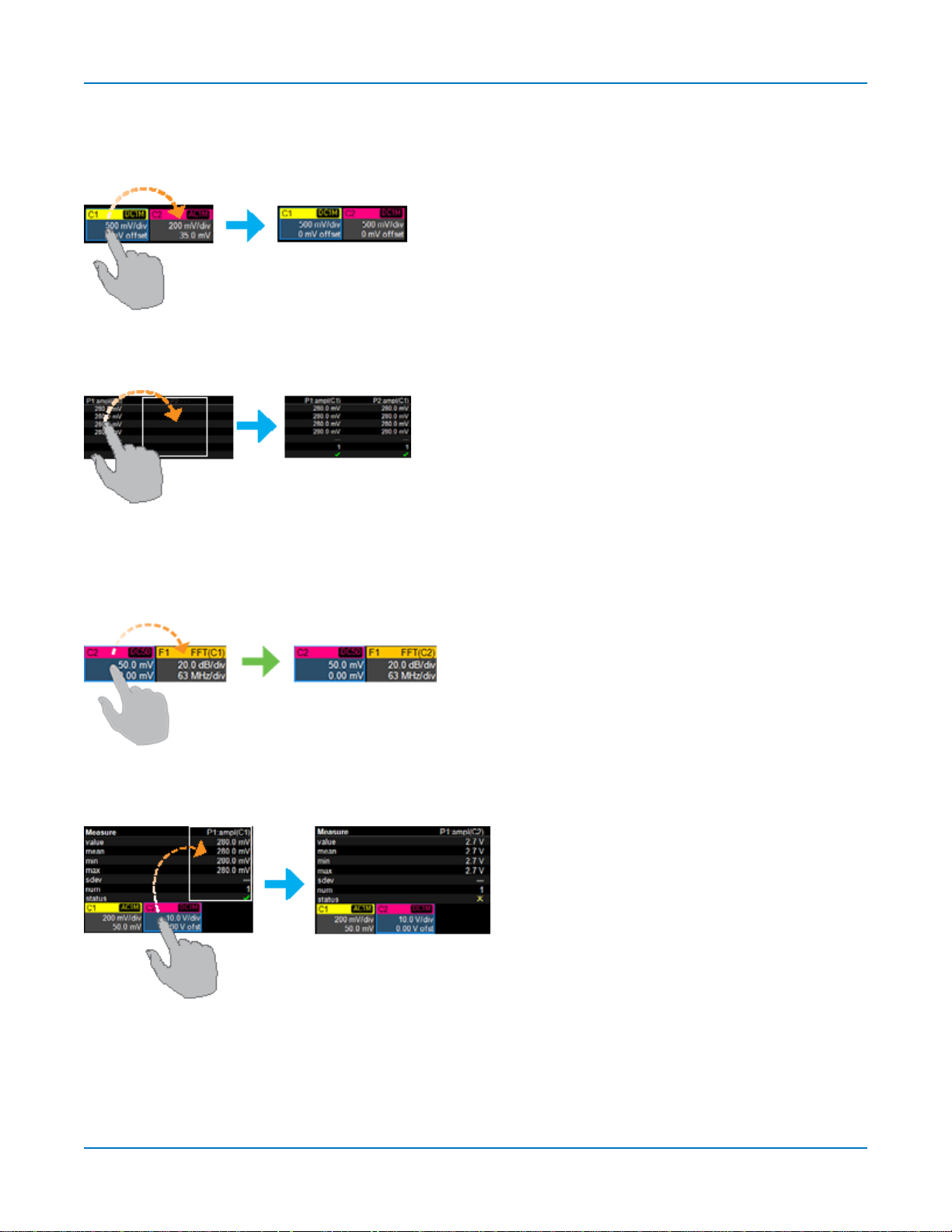
Copy Setups
Tocopythesetupofone traceto another of the same type(e.g.,channeltochannel,mathto math),drag-
and-dropthesourcedescriptor boxonto the target descriptor box.
Tocopythesetupofa measurement(Pn),drag-and-dropthe source column onto the target columnof the
Measuretable.
Change Source
Tochange thesourceofa trace,drag-and-dropthedescriptor boxof the desiredsource ontothetarget
descriptor box.You can alsodropit on the Sourcefieldof the target setup dialog.
Tochange thesourceofa measurement,drag-and-dropthedescriptor boxof thedesiredsource onto the
parameter (Pn)column of theMeasuretable.
19
WaveSurfer 4000HD Oscilloscopes Operator's Manual
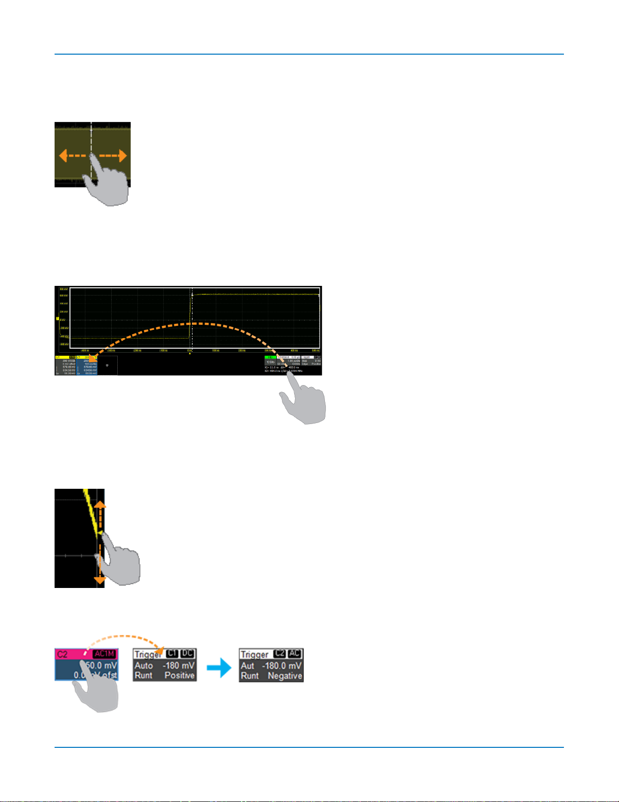
Position Cursors
Tochange cursor measurementtime/level,dragcursor markersto new positionson thegrid.The cursor
readout willupdate immediately.
Toplacehorizontalcursorson zoomsorothercalculatedtraceswherethesourceHorizontalScalehas
forced cursorsoff thegrid,dragthecursorreadout from belowtheTimebasedescriptortothe gridwhere
youwish toplacethecursors.The cursorsare set at the 2.5and7.5 divisionsof the grid.Cursorson the
sourcetracesadjust positionaccordingly.
Change Trigger
Tochange thetriggerlevel,drag theTriggerLevelindicator toanew positionon the Yaxis.The Trigger
descriptor boxwillshow the new voltage Level.
Tochange thetriggersource channel,drag-and-dropthedesiredchannel(Cn)descriptor boxonto the
Triggerdescriptor box.The triggerwillrevert tothecouplingandslope/polarity last set onthat channel.
20
Using MAUI
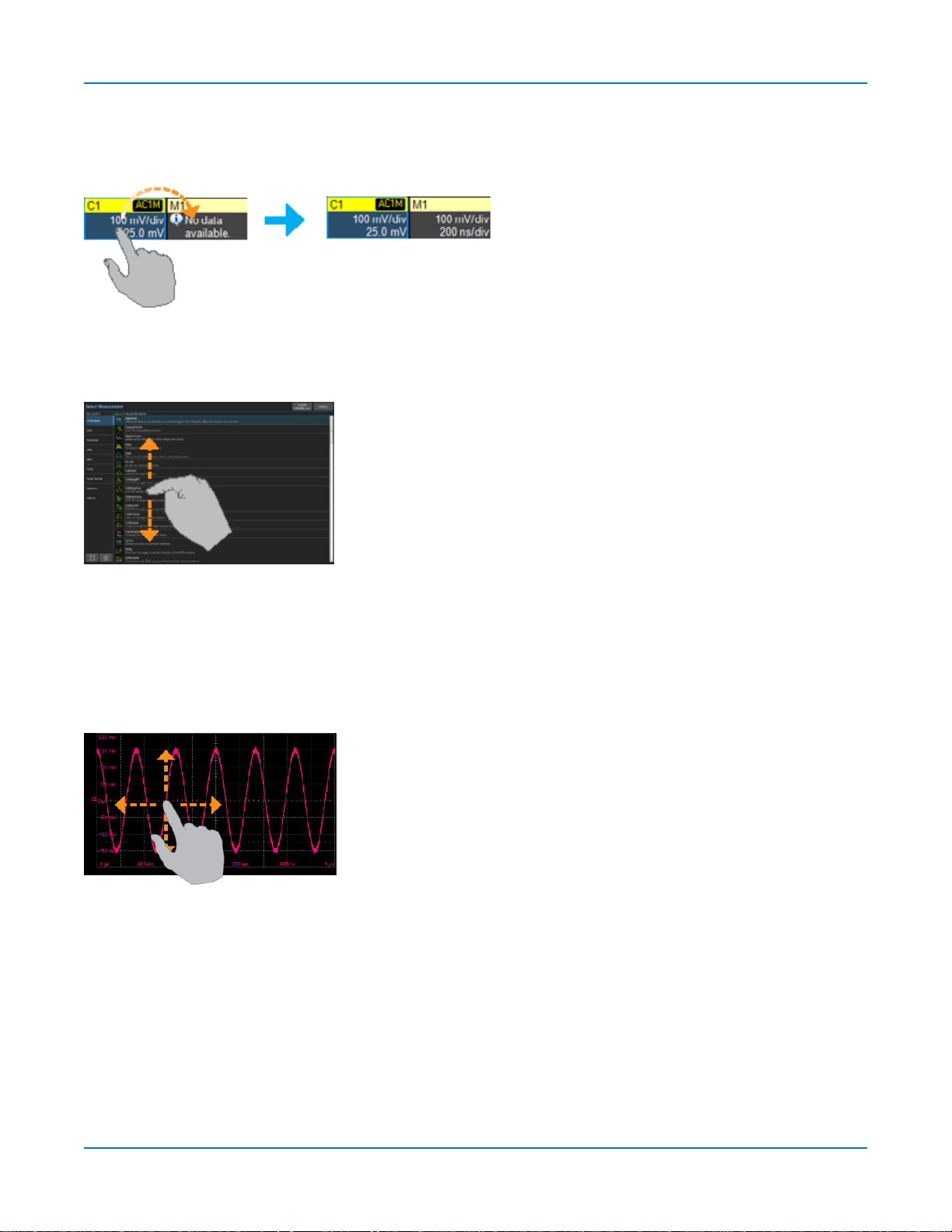
Store to Memory
Tostore a tracetointernalmemory,drag-and-dropits tracedescriptor boxonto the target memory(Mn)
descriptor box.
Scroll
Toscrolllonglistsofvaluesorreadout tables,swipethe selectiondialogor tableinan upordowndirection.
Pan Trace
Topana trace,activateit to bringit to the forefront,then dragthe waveform trace right/left or up/down. If
it is thesourceof anyothertrace,that trace willmove,aswell.
For channeltraces,the Timebasedescriptor boxwillshow the new Horizontal Delay value.Forother
traces,thezoom factor controlsshowthe new HorizontalCenter.
21
WaveSurfer 4000HD Oscilloscopes Operator's Manual
Working WithTraces
Traces arethevisiblerepresentationsof waveforms that appear onthe displaygrid.Theymay show live
inputs(Cn,Digitaln),amath function applied to a waveform (Fn),astored memory of awaveform (Mn),a
zoom of awaveform (Zn),or the processingresults of specialanalysissoftware.
Traces areatouch screen object likeanyother andcan bemanipulated.Theycanbepanned,moved,
labeled,zoomed andcapturedindifferent visualformats for printing.
Each visibletracewillhaveadescriptor boxsummarizingits principalconfigurationsettings.See
OneTouch Helpfor moreinformationabout how youcanusetracesandtrace descriptor boxestomodify
yourconfigurations.
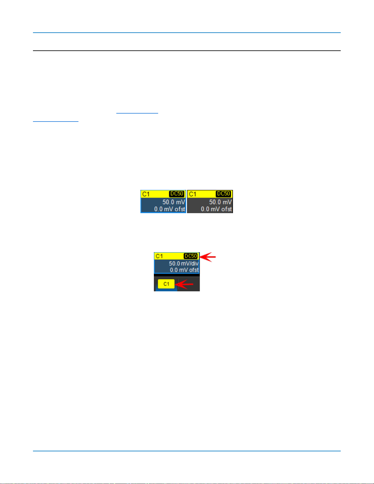
Active Trace
Althoughseveraltracesmaybeopen,onlyonetrace isactiveandcan be adjustedusingfront panel
controlsand touch screengestures. Ahighlighteddescriptor boxindicateswhich traceisactive.All
actionsapplyto that trace untilyou activate another.Touch thetrace descriptorboxto makeit theactive
trace (andtheforegroundtrace inthat grid).
Activetracedescriptor(left),inactivetracedescriptor(right).
Wheneveryouactivateatrace,thedialog at the bottom of thescreenautomaticallyswitchesto the
appropriate setupdialog.
Activedescriptorboxmatchesactivedialog tab.
Foreground Trace
Since multipletracescan beopenedonthe samegrid,thetrace shown ontop of the othersisthe
foregroundtrace. Grid indicators(matchedto the input channelcolor) represent the foregroundtrace.
Touch a trace or itsdescriptor boxtobringit totheforeground.Thisalsomakesit theactivetrace.
Notethat a foreground tracemay not bethe same as theactivetrace.Atrace in aseparategridmay
subsequentlybecome theactivetrace,but the indicatorson a givengrid willstillrepresent the foreground
trace inthat group.
22
Using MAUI
Turning On/Off Traces
TurnOn/OffAnalogTrace
Toturn on a channeltrace,do anyof the following:
l From thefront panel,pressthe Channelbutton.
l From thetouchscreen,chooseVertical> ChannelxSetup.
l Touch the AddNewboxandselect Channel,or draganother Channel(Cn) descriptor boxtotheAdd
Newbox.
Toturn off a trace,pressthe front panelChannelbuttonasecondtime,or touch thedescriptor boxto
openthesetup dialogandcleartheTrace Oncheckbox.
TurnOn/OffDigitalTrace
From the touch screen,chooseVertical>DigitalnSetupthencheckGroupon theDigitalndialog.
Turnoff the trace,cleartheGroup checkbox.
TurnOn/OffZoomTrace
See Creating Zooms.
TurnOn/OffOtherTrace
Toturn on/off math or memorytraces,check or clearthe TraceOn boxon the respectivesetupdialogs.
You can alsotouch the AddNewboxandselect the trace type,or drag anotherdescriptor boxof that type
tothe AddNew box(e.g.,dragM1 to AddNew toturnona the next available memorytrace).
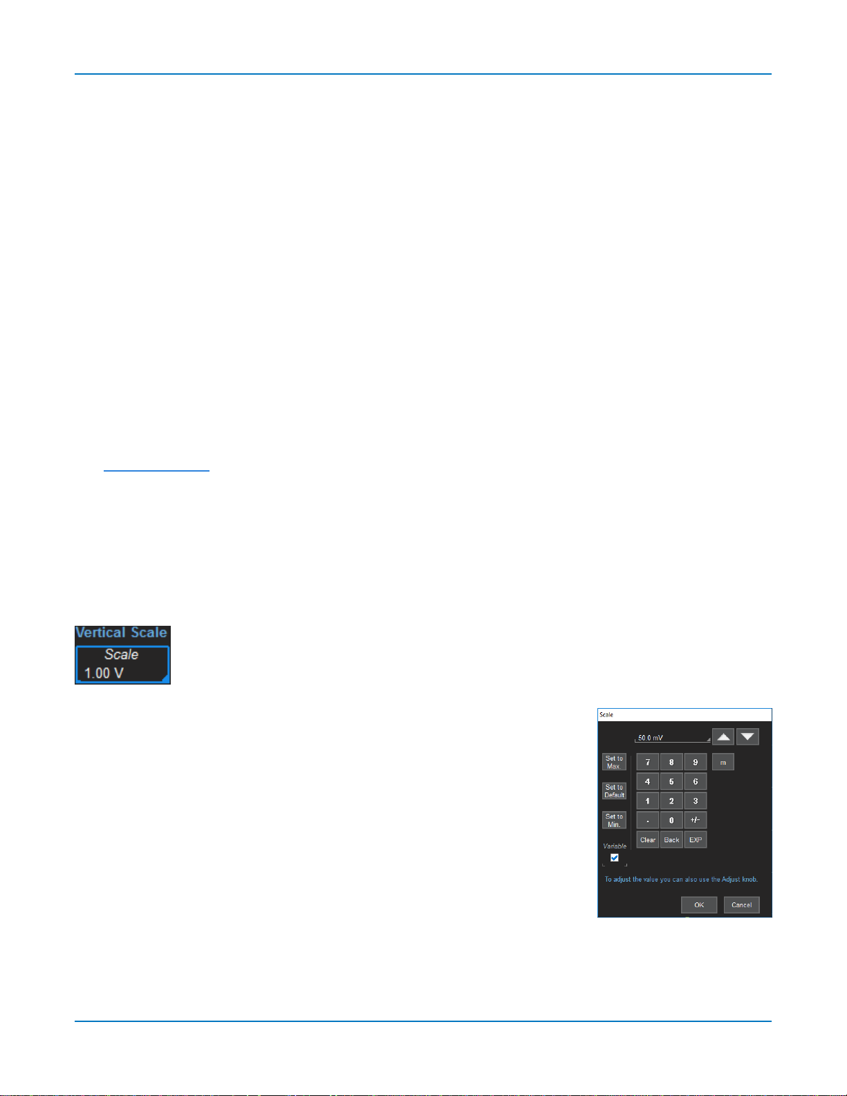
Adjusting Traces
Toadjust VerticalScaleandOffset,or HorizontalScaleandDelay,just activate the trace
andusethefront panelknobs.To makeother adjustments—suchas units—touchthe
trace descriptorboxtwice toopenthe appropriatesetup dialog.
Many settingscanbeadjusted byselectingfrom the pop-up
that appearswhenyoutouch a control. When an entryfieldappears
highlightedinblueafter touching,it is activeand canbe adjusted byturning
thefront panelknobs.Fields that don't havea dedicated knob(as do
Vertical Leveland HorizontalDelay)canbemodifiedusingthe Adjust knob.
If youhavea keyboardinstalled,youcan typeentriesin an active
(highlighted)data entryfield.Or,you can touch again,then "type"theentry by
touchingkeyson thevirtualkeypad or keyboard.
Tousethevirtualkeypad,touch the soft keysexactly asyou woulda
calculator. When you touch OK,thecalculatedvalueis entered in thefield.
23
WaveSurfer 4000HD Oscilloscopes Operator's Manual
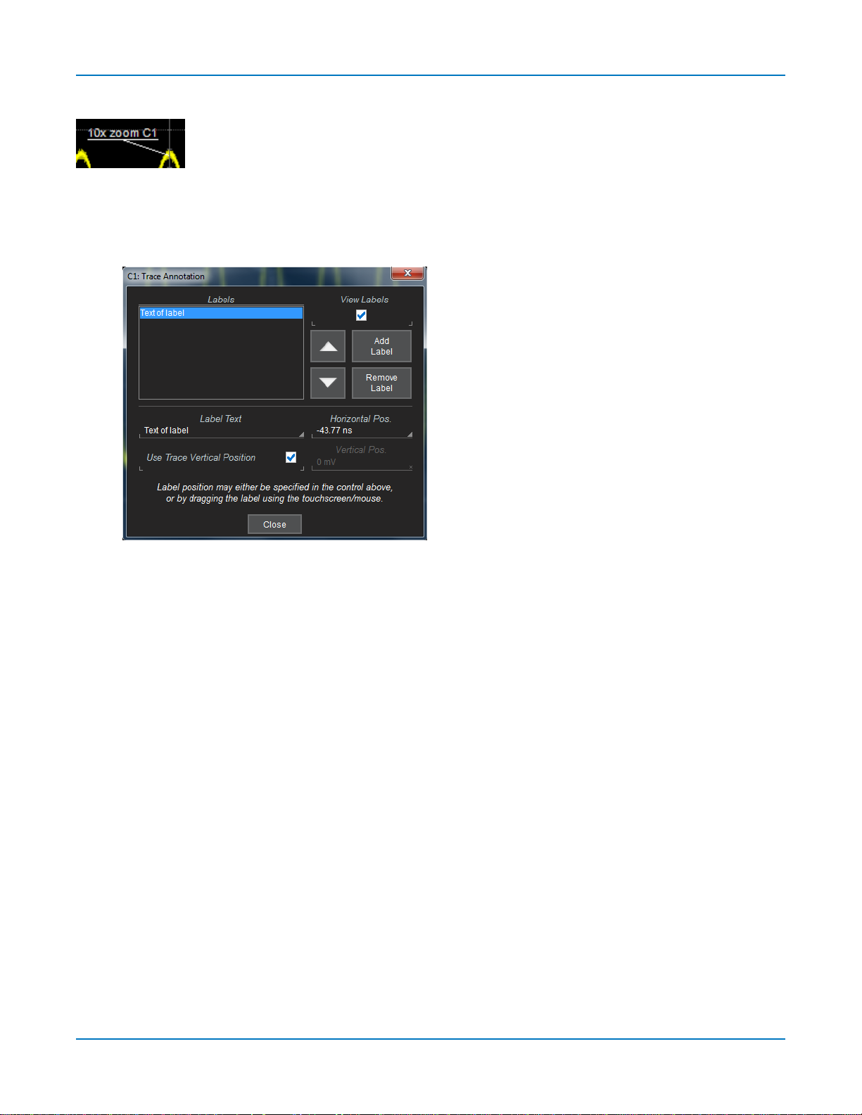
Labeling Traces
TheLabelfunctiongivesyoutheability toaddcustom annotationsto the trace display.
Onceplaced,labelscanbe movedto new positionsor hiddenwhileremaining
associatedwith the trace.
CreateLabel
1. Select Labelfrom thecontext menu,ortouch theLabelActiontoolbarbutton onthetracesetup
dialog.
2. OntheTrace Annotation pop-up,touch AddLabel.
3. Enter theLabelText.
4. Optionally,enter the HorizontalPos.andVerticalPos.(in same units asthetrace) at whichto place
thelabel.The default positionis0 nshorizontal. Use TraceVerticalPositionplaces thelabel
immediatelyabovethe trace.
RepositionLabel
Drag-and-drop labelstoreposition them,or changethe positionsettingsontheTrace Annotation pop-up.
Edit/RemoveLabel
On theTrace Annotationpop-up,select theLabelfrom thelist.Changethe settingsasdesired,or touch
Remove Labeltodeleteit.
ClearView labelsto hidealllabels. Theywillremaininthe list.
24
 Loading...