

Page 1
PCI Express® 4.0 to U.2/U.3 Host Adapter
User Manual and Quick Start Guide
1
Introduction
Use this document for quick installation and setup.
Teledyne LeCroy's Gen4 U.2/U.3 Host Adapter provide a quick and simple means for test and debug of Solid State Drives
(SSDs) based on PCI Express (PCIe) protocols. They support data rates of 2.5 GT/s, 5.0 GT/s, 8.0 GT/s and 16.0 GT/s.
Each host adapter also supports side band signals such as PERST#, WAKE#, CLKREQ# and SMBus (SMBCLK, SMBDAT).
There are five different host adapter cards. All the adapters have similar features and only difference is how the links are
connected between the U.2/U.3 connector and the PCIe CEM Edge fingers:
Port A U.2 x4 Routing 4 lanes of port A from U.2 connector straight to the bottom PCIe CEM edge fingers.
Port B U.2 x2 Routing 2 lanes of port B from U.2 connector to the bottom PCIe CEM edge fingers (L0 and L1).
Port A U.3 x4 Routing 4 lanes of port A from U.3 connector straight to the bottom PCIe CEM edge fingers.
Port A U.3 x2 Routing 2 lanes of port A from U.3 connector straight to the bottom PCIe CEM edge fingers (L0 and L1).
Port B U.3 x2 Routing 2 lanes of port B from U.3 connector to the bottom PCIe CEM edge fingers (L0 and L1).
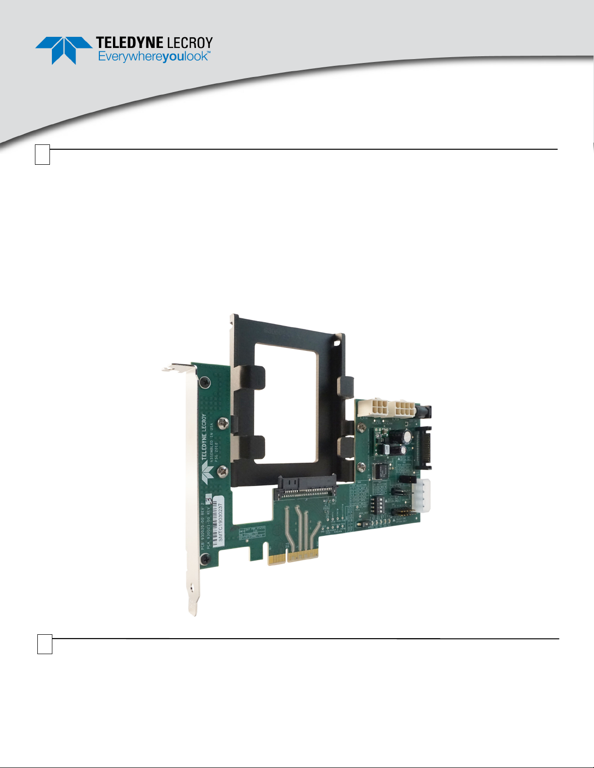
U.2/U.3 Host Adapter Card
2
Components
The adapter package includes the following components:
• U.2/U.3 Host Adapter card
• Half height bracket
Inspect the received shipping container for any damage. Unpack the container and account for each of the system
components listed above. Visually inspect each component for absence of damage. In the event of damage, notify the
shipper and Teledyne LeCroy. Retain all shipping materials for shipper’s inspection.
• Power supply (+12V @ 3A)
• User Manual and Quick Start Guide (this document)
Page 2
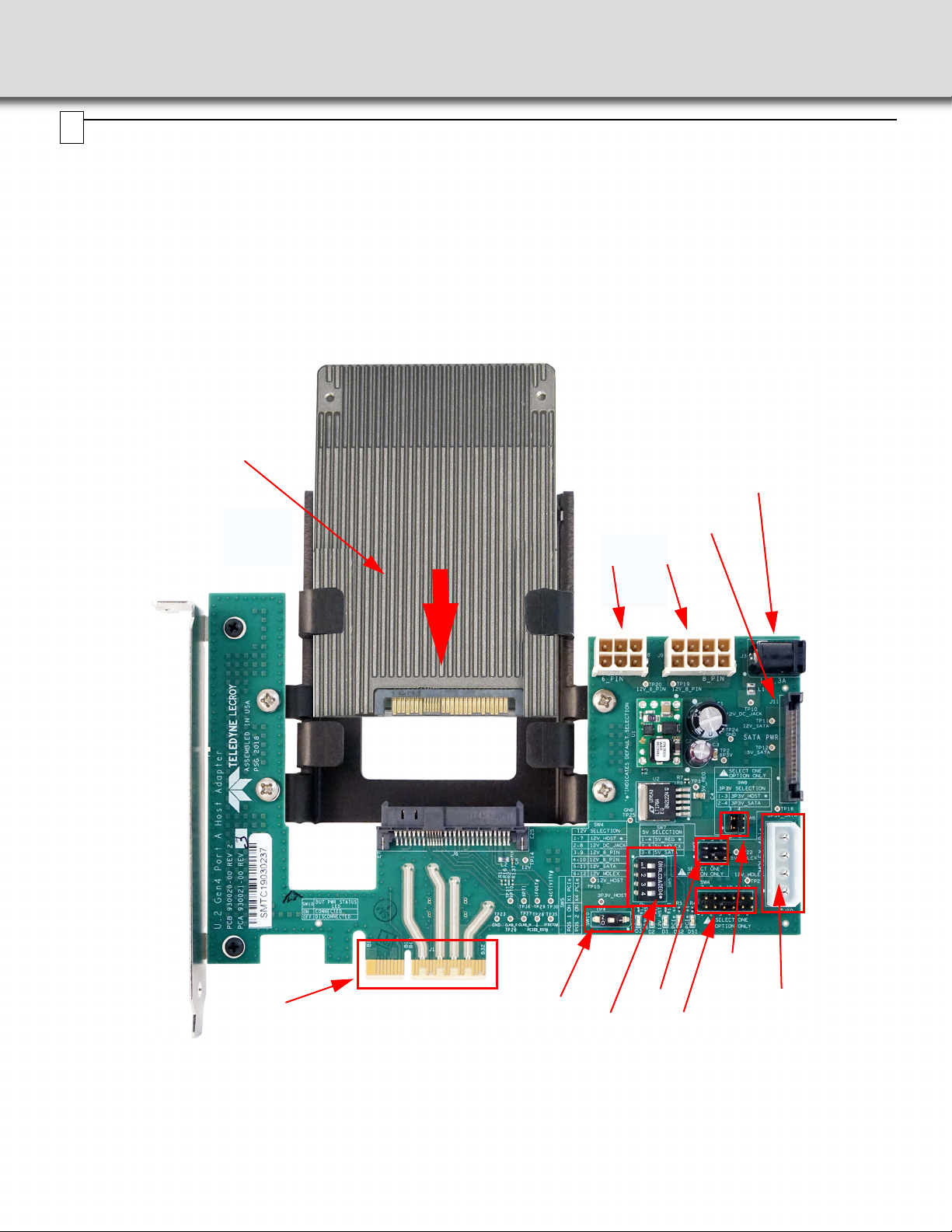
Connections
PCI Express (PCIe) Interface
(plugs into PCI Express slot)
Device
Under
Te st
(DUT)
SW5
SW4
External power jack J3
12V @ 3A minimum
Note: See Section 4 for
switch configurations
SW7
SW8
J8 J9
Note: See Section 5 for J8
and J9 pin out
J11: SATA
Connector
J10: Molex
Connector
SW10
3
Perform to the following steps to connect each U.2/U.3 Host Adapter (see the sample image below):
1. Insert the U.2/U.3 device under test (DUT) through the 2.5" bracket making sure it connects properly in the top side of
the U.2 connector.
2. Make sure the power for the DUT is sourced correctly using switches SW4, SW7, and SW8. The factory default posi-
tions are SW5.1 OFF, SW5.2 ON, SW5.3 OFF, SW5.4 OFF, SW4 shunts 1-7, SW7 shunts 1-4, SW8 shunts 1-3. See
the tables below to source the correct power for the DUT.
3. Make sure only switch 2 from the DIP switch array SW5 is in the ON position. The PRSNT# pins configuration is x1 or
x4 device is selected using SW5 according to the table.
4. Plug the adapter with the device under test in any PCI Express slot.
5. Connect the power supply to the external power jack (J3) if needed.
Page 3

4
Configuration
Table 1: SW4
Shunt 12 V Source Selection
1 --> 7 12V from Host (PCIe Edge connector) -- [Default]
2 --> 8 12V from DC Jack J3
3 --> 9 12V from 6 pin connector J8
4 --> 10 12V from 8 pin connector J9
5 --> 11 12V from SATA connector J11
6 --> 12 12V from Molex connector J10
Table 2: SW5
SW5.1 SW5.2 SW5.3 SW5.4 Boot Configuration
OFF OFF X X Reserved
ON OFF X X x1 PCIe
OFF ON X X x4 PCIe (see note below) --
ON ON X X Reserved
Note: Up to x2 for Port B Adapter.
[Default]
Table 3: SW7
Shunt 5V Source Selection
1 --> 4 5V from Internal regulator -- [Default]
2 --> 5 5V from Molex connector J10
3 --> 6 5V from SATA connector J11
Note: 5V from internal regulator is derived from the 12V power source selected
with SW4.
Table 4: SW8
Shunt 3.3V Source Selection
1 --> 3 3.3V from Host (PCIe Edge connector) -- [Default]
2 --> 4 3.3V from SATA connector J11
Table 5: SW10
DUT Power Staus LEDs
ON LED Connected [Default]
OFF LED Disconnected
5
Power Connections
Table 6: J8 Power Connector
Pin Description Pin Description
1+12V 4 GND
2NC 5 NC
3+12V 6 GND
Table 7: J9 Power Connector
Pin Description Pin Description
1 +12V 5 GND
2 +12V 6 NC
3 +12V 7 GND
4NC 8 GND
6
Swapping the Full Height Bracket for the Half Height Bracket
Locate the two screws on the front of the Host Adapter securing the Full Height Bracket.
Using a Phillips head screw driver, remove the two screws that secure the full height bracket. Save the screws for installation of the half
height bracket.
Gen4 U.2/U.3 Host Adapter with Full Height Bracket: Attached and Removed
Page 4

Locate the Half height bracket and the two screws from the disassembly process.
Using a Phillips head screw driver use the two screws from the disassembly process to secure the half height bracket to the Host
Adapter. See drawings below.
Gen4 U.2/U.3 Host Adapter with Half Height Bracket: Attached and Secured
7
Available Test Points
Test Point
Number Test Point Name
TP2 6.5V TP14 12V
TP3 5V_REG TP16 3.3V_SATA
TP4 3.3V_HOST TP19 12V_8_PIN
TP10 12V_DC_JACK TP20 12V_6_PIN
TP11 12V_SATA TP21 12V_MOLEX
TP12 5V_SATA TP22 5V_MOLEX
8
Environmental Conditions
• Temperature: Operating 32° F to 122° F (0° C to 50° C)
• Temperature: Non-Operating 14° F to 176° F (-10° C to 80° C)
• Humidity: Operating 10% to 90% RH (non-condensing)
Tes t P oin t
Number Test Point Name
Teledyne LeCroy Customer Support
Online Download
Periodically check the Teledyne LeCroy Protocol Solutions Group
web site for software updates and other support related to this
product. Software updates are available to users with a current
Maintenance Agreement.
Test Point
Number Test Point Name
TP23 GND TP29 IFDET
TP24 GND TP30 ACTIVITY
TP25 GND TP35 PERSTA
TP26 REFCLKB_P TP37 REFCLKA_P
TP27 REFCLKB_N TP38 REFCLKA_N
TP28 PERSTB TP29 IFDET
Web:
E-mail: psgsupport@teledyne.com
Support: teledynelecroy.com/support/contact
teledynelecroy.com/tm/software/PCIe
Test Point
Number Test Point Name
Trademarks and Servicemarks
Teledyne LeCroy is a trademark of Teledyne LeCroy. All other
trademarks are property of their respective companies.
Changes
Product specifications are subject to change without notice.
Teledyne LeCroy reserves the right to revise the information in thi s
document without notice or penalty.
Copyright
© 2019 Teledyne LeCroy, Inc. All rights reserved. Part Number: 930403-00 Rev B
This document may be printed and reproduced without additional permission, but all copies should contain this copyright notice.
 Loading...