

Page 1
Quick Start
Guide
Computer System Requirements
Supported Systems
l Operating System: Windows 7/8/10
l USB:USB 2.0 and later
Minimum Requirements
l Processor: Core i5 at 2.7 GHz
l RAM: 4 GB
l Free Hard Disk Space on C: drive: 20 GB
1. Sodera LE Front Panel
Install Software
l From Download: Download the latest ComProbe installer
from FTE.com. Once downloaded, double-click the
installer and follow the directions.
http://www.fte.com/soderale-soft
Frontline Sodera LE front panel is shown below. The panel provides controls to power up and shut down the Frontline Sodera LE
hardware, and it provides indicators to show the power and capture status.
Control Description
ANTENNA
Connect to the front panel antenna SMA connector. Used for wideband wireless capture of Bluetooth low energy
transmissions.
Maximum useable signal level: -10 dBm.
WIRED
Low sensitivity RF input suitable for conductive testing that utilizes a wired connection from the devices under test
(DUTs). Conductive testing allows for isolation of the DUTs from environmental interference.
Frontline Technical Support: Phone +1-434-984-4500 or email tech_support@fte.com
Sodera LE Front Panel Controls and Indicators
Table 1 - Sodera LE Front Panel Controls
Page 2
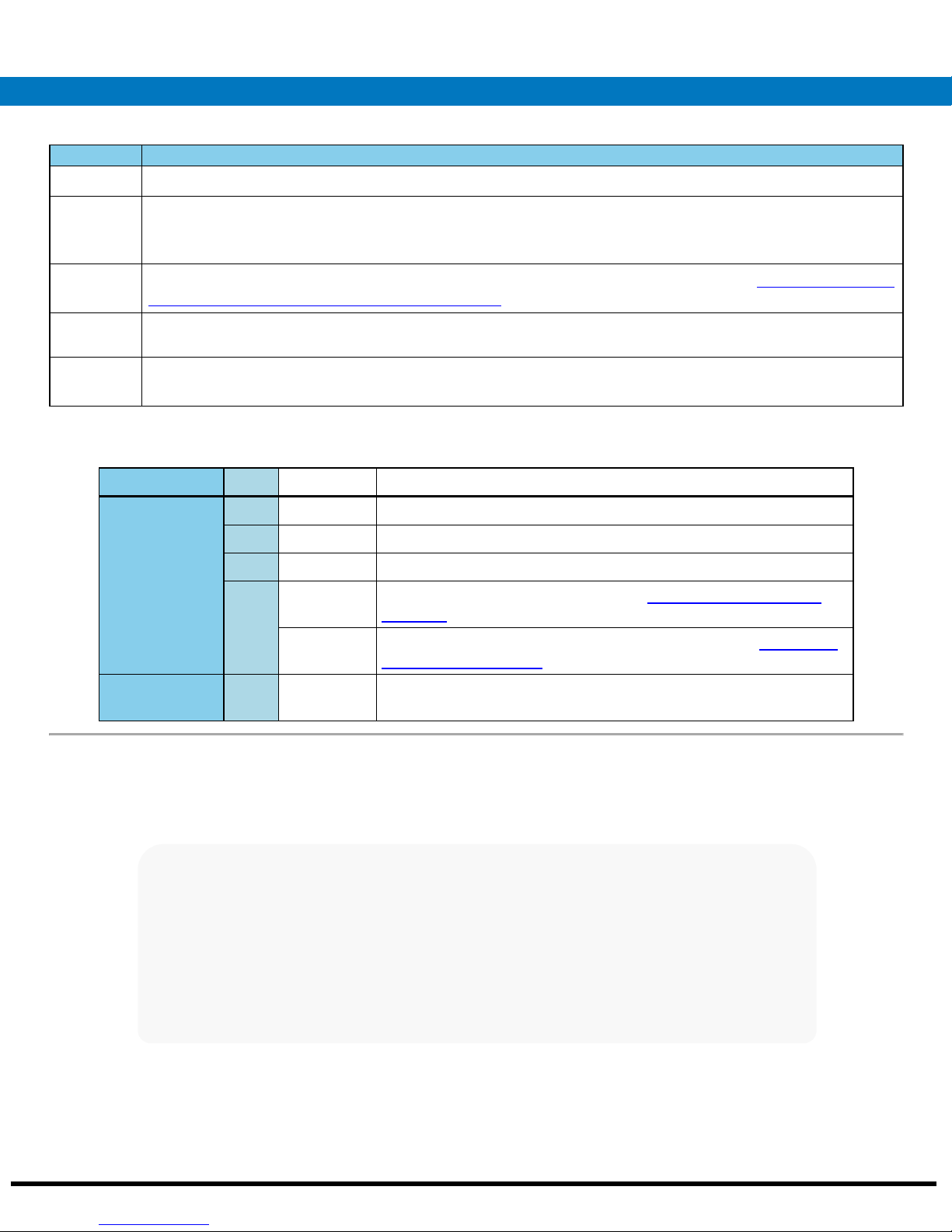
Table 1 - Sodera LE Front Panel Controls (continued)
Control Description
Maximum useable signal level: 27 dBm.
OVERLOAD
POWER
EXT
CLOCK
Power
Button
Power None Off Unit is powered off.
RF overload indicator. If the RF signal level on either the ANTENNA or WIRED connector is too high, then this
LED will light red. RF overload occurs when the signal level is greater than 27 dBm. Should an RF overload occur
with the ANTENNA in use, try switching to the less sensitive WIRED connecter to relieve the problem.
LED illuminates when the Sodera LE unit has been powered up using the power button. See
Front Panel Power and Overload Indicators on page 2
for more information.
Table 2 - Sodera LE
Not used.
Press and then release the button to power on or power off the system.
Table 2 - Sodera LE Front Panel Power and Overload Indicators
Indicator Color State Status Indicated
Green Constant Unit is powered on.
Amber Constant Unit is powering on.
Red Blinking Unit has reached thermal overload. See
next page
.
Constant Unit has reach thermal overload and has shut down. See
Power, on the next page
.
4. Applying Power, on the
4. Applying
Overload Red Occassional Illuminates each time RF power at the Antenna or Wired connectors
has exceeded 27 dBm.
2. Sodera LE Rear Panel Connectors
The rear panel is shown below. The panel provides connectors for external power and for connection to the computer hosting the
Frontline software.
Sodera LE Rear Panel Connectors
DC9V: 1.7 mm jack connector to the Frontline supplied AC-to-9 VDC power adapter.
Frontline Technical Support: Phone +1-434-984-4500 or email tech_support@fte.com
Page 3
USB : USB 2.0 port for connecting the Sodera LE unit to the host computer where the Frontline software resides. This connector
provides host computer command, control, and data transfer.
Note: All other connectors are not used.
3. Attach Antenna
Antenna Attachment Point
Remove the Frontline Sodera LE hardware from the box and attach the antenna to the ANTENNA SMA connector on the front panel.
4. Applying Power
The Sodera LE hardware is powered by an external 9 VDC power source using an AC-to-DC power adapter.
Note: Only use the Frontline supplied power. Do not substitute with another power adapter.
To apply power to the Sodera LE hardware, connect the provided AC-to-DC power adapter to the DC9V connector on the rear panel
and then connect the adapter into an AC source.
To start the Sodera LE hardware, depress the Power button on the front panel and then release. This action will provide a clean start
for the Sodera LE hardware.
The front panel Power LED indicator will be green.
Should the Sodera LE hardware reach thermal overload temperature between 50 °C and 60 °C (122 °F and 140 °F), it will shut down.
Frontline Technical Support: Phone +1-434-984-4500 or email tech_support@fte.com
Page 4

If the fan becomes blocked, the Sodera LE
unit will power down. Should this happen
check that nothing is blocking the airflow to
the unit's air inlet, or that nothing is impeding
the fan from spinning freely. Clear any
obstructions and then apply power to the
unit.
5. Sodera LE Data Capture Method
When the Frontline Sodera LE is connected to the Host PC running Frontline software, the Select Data Capture Method... window will
display the Sodera LE options.
Sodera LE Data Capture Method
Select Wideband Bluetooth, Low energy (Sodera LE)
Click on Run. The Frontline software will display the Sodera LE Control window.
Frontline Technical Support: Phone +1-434-984-4500 or email tech_support@fte.com
Page 5

6. Control Window
7. Sodera Window - Datasource
Sodera LE Control Window
Sodera LE Datasource Window
8. Sodera LE: Record—Begin Capture
When starting a capture session
l the active status of all devices is cleared in the Wireless Devices panes ,
l the Security pane is emptied, and
l the Event Log pane retains all prior logged events.
On the Capture Toolbar, click on the Record button, or select Record from the Capture menu option. When
the Record button changes to Recording, Sodera LE hardware is capturing data from all active Bluetooth
devices within range and is recording data on the PC.
On the Capture Toolbar, clicking on the Recording button, or selecting Recording from the Capture menu
options will halt live capture.
The Wireless Devices pane populates with any newly discovered devices. Selecting devices for analysis can be
done while recording.
Note: The Capture Toolbar Analyze button will be grayed out until some wireless devices have been selected for
analysis.
Frontline Technical Support: Phone +1-434-984-4500 or email tech_support@fte.com
Page 6

The Security pane will show all encrypted Bluetooth links.
The Event Log pane will begin to populate with information, warnings, and error messages.
The Status Bar will show a running total of captured packets.
Note: Starting a new capture session will clear all unsaved data from both the Sodera LE hardware and the
Frontline software. If it has not been saved, then a pop-up warning message will appear.
9. Sodera LE: Selecting Devices for Analysis
Once a Sodera LE capture session starts by clicking on Record on the Capture Toolbar, data from all active devices within range or data
from wired connections is being captured. To analyze the data using the Frontline software, you select specific devices of interest to
include in the analysis.
Sodera LE Wireless Devices Pane
In the Wireless Devices pane, place a check in the row of each active device to be analyzed. Active devices can also be selected
while the recording is in process.
Note: Data filtered by the device selection is an “OR” function, not an “AND” function. When selecting device1,
device2, device3,... the recorded data filtered into the analyzer is data involving device1 OR device2 OR device3
OR .... However, if in the Options menu, analysis if LE Empty packets is selected an AND function is included.
For example: (device2 AND LE Empty packets) OR (device3 AND LE Empty packets).
The following table lists some common data capture and device selection scenarios.
Table 3 - Common Data Capture and Device Selection Scenarios
Scenario Wireless Devices Pane Selection
Analyzing traffic between a slave Device Under Test (DUT) and its master. Select only the slave DUT for analysis
Analyzing all traffic on a piconet Select the Master for analysis
The Sodera LE is now ready to begin protocol- and event-level analysis.
Frontline Technical Support: Phone +1-434-984-4500 or email tech_support@fte.com
Page 7

10. Sodera LE: Starting Analysis
The analysis begins by clicking on the Analyze button, or selecting Analyze from the Capture menu.
Alternatively, click on the Start Analyze button In the Control window. The Sodera LE hardware will begin
sending captured packets involving the selected device to the Frontline software.
Once analysis has begun, you cannot change the device selection. All device rows in the Wireless Devices pane
are grayed-out. To stop the analysis, click on the Analyzing button. You can then change your device selection
and restart analysis by clicking on the Analyze button.
To stop the Analysis click on the Analyzing button or click on the Control window Stop Analyze button .
Conducting analysis from a capture file is identical to the live capture method.
11. Capturing Sodera LE Analyzed Data to Disk
Note: Record is not available in Viewer mode. Analyze/Analyzing is available in Viewer mode, allowing different
analyses to be performed on previously recorded and saved captures.
1.
Click the Record button on the Standard Toolbar. Sodera LE will begin capturing data from all wireless devices
within range .
2. In the Wireless Devices pane select the active devices for analysis
3.
Click on Analyze button , or click the Start Analyze button to begin capturing to a file. This Start Analyze
button is located on the Control window, Event Display, and Frame Display.
4. Files are placed in My Capture Files by default and have a .cfa extension. Choose Directories from the Options menu on the
Control window to change the default file location.
5. Watch the Status Bar on the Control window to monitor how full the file is. When the file is full, it begins to wrap, which means
the oldest data will be overwritten by new data.
6.
Click the Analyzing button, or click the Stop Analyze button to stop analyzing. .
7.
To clear captured data, click the Clear icon .
l If you select Clear after stopping analysis, a dialog appears asking whether you want to save the data.
o
You can click Save File and enter a file name when prompted .
o
If you choose Do Not Save, all data will be cleared.
o
If you choose Cancel, the dialog closes with no changes.
l If you select the Clear icon while a capture is occurring:
o
The capture stops.
o
A dialog appears asking if you want to save the capture
o
You can select Yes and save the capture or select No and close the dialog. In either case, the existing capture file
is cleared and a new capture file is started.
o
If you choose Cancel, the dialog closes with no changes.
Note: The Sodera LE/Frontline software system does not support host PC hibernation or sleep mode. If the PC
does inadvertently go into hibernation or sleep mode, the user should close and then restart the Frontline software.
Frontline Technical Support: Phone +1-434-984-4500 or email tech_support@fte.com
Page 8

12. Sodera LE Technical Specifications/Service Information
l Dimensions: 160 mm wide X 56 mm tall X 167 mm deep (6.3” X 2.2" X 6.6" )
l Weight: 1.4 kg (3.1 lb)
l Humidity: Operating: 0% - 90% (0 °C – 35 °C), non-condensing
l Temperature: 0 °C to +40 °C (32 °F to +104 °F)
l Power Input: 9 VDC (tip positive)
l Max Power: 12 W
Service Notes
The Sodera LE hardware does not contain any user serviceable items. Any repairs and maintenance must be performed by a service
technician that has been trained and approved by Frontline.
Before any service is performed on the Sodera LE hardware, all power sources must be removed. This includes disconnecting any
power sources from the DC9V input power connector on the rear panel.
This quick start guide provides sufficient information to begin the data capture. Detailed hardware and software information is
contained in the Sodera LE User Manual. The manual is available on FTE.com.
© 2017 Teledyne LeCroy, Inc.
The Bluetooth SIG owns the Bluetooth word mark and logos, and use of such marks is under license.
Publish date: 1/17/2017
Frontline Technical Support: Phone +1-434-984-4500 or email tech_support@fte.com
 Loading...