

Page 1

Harmony™ Test System User Manual
Page 2

Copyright © 2019 Teledyne LeCroy, Inc.
Frontline is a registered trademark of Teledyne LeCroy, Inc.
The following are trademarks of Teledyne LeCroy, Inc.
The Bluetooth SIG, Inc. owns the Bluetooth® word mark and logos, and any use of such marks by
Teledyne LeCroy, Inc. is under license.
All other trademarks and registered trademarks are property of their respective owners.
Frontline Harmony Hardware & Software User Manual 2
Page 3

Table of Contents
What is in this manual .............................................................................................................................. 5
Chapter 1. Frontline Hardware & Software .................................................................................................. 6
1.1 Computer Minimum System Requirements ....................................................................................... 6
1.2 Software Installation ........................................................................................................................... 6
1.3 Harmony Firmware ............................................................................................................................. 8
1.4 Sodera Firmware ................................................................................................................................. 9
Chapter 2. Getting Started .......................................................................................................................... 11
2.1 Harmony Hardware .......................................................................................................................... 11
2.1.1 Attaching Cables for Conductive Operation .................................................................................. 11
2.1.2 Attaching Antenna for Over-the-Air Operation ............................................................................. 13
2.1.3 Connecting/Powering the Frontline Harmony ............................................................................... 14
2.1.4 Launching the Software ................................................................................................................. 19
Chapter 3. Configuration Settings ............................................................................................................... 21
3.1 Configuring the Software .................................................................................................................. 21
3.1.1 Project Settings .............................................................................................................................. 21
3.1.2 Tester and IUT Configuration ......................................................................................................... 22
3.1.3 IXIT Data ......................................................................................................................................... 24
3.1.4 IUT Information .............................................................................................................................. 24
Chapter 4. Running Tests ............................................................................................................................ 26
4.1 Selecting Tests .................................................................................................................................. 26
4.1.1 HCI .................................................................................................................................................. 26
4.1.2 Link Layer ....................................................................................................................................... 28
4.1.3 Importing Tests .............................................................................................................................. 47
4.2 Initiating Tests .................................................................................................................................. 48
4.2.1 Run Tests ........................................................................................................................................ 48
4.2.2 Running Harmony Projects Unattended ........................................................................................ 49
Chapter 5. Test Results ............................................................................................................................... 51
5.1 On-Screen Test Results .................................................................................................................... 51
5.1.1 Results Pane ................................................................................................................................... 51
5.1.2 Review Previously Run Tests .......................................................................................................... 53
5.2 Produce Test Result Reports ............................................................................................................ 54
5.2.1 Reports ........................................................................................................................................... 54
Frontline Harmony Hardware & Software User Manual 3
Page 4

5.3 Results Files ...................................................................................................................................... 56
5.3.1 Location .......................................................................................................................................... 56
5.3.2 Log/Capture Files ........................................................................................................................... 57
Chapter 6. General Information .................................................................................................................. 58
6.1 More Help ......................................................................................................................................... 58
6.1.1 Frontline Software ......................................................................................................................... 58
6.1.2 User Assistance .............................................................................................................................. 58
Chapter 7. Regulatory ................................................................................................................................. 59
7.1 Certifications ..................................................................................................................................... 59
7.1.1 FCC - Federal Communications Commission ................................................................................. 59
7.1.2 RED - Radio Emissions Directive .................................................................................................... 59
7.1.3 ISED - Innovation, Science and Economic Development (RSS Radio Standards Specification)..... 59
Frontline Harmony Hardware & Software User Manual 4
Page 5

What is in this manual
The Frontline Harmony Test System User Manual comprises the following chapters, which are organized
in the sequence you would normally follow to perform validation testing: set up, configure, test, report.
You can read them from beginning to end to gain a complete understanding of how to use the Frontline
Harmony hardware and software or you can skip around if you only need a refresher on a particular
topic. Use the Contents, Index, and Glossary to find the location of particular topics.
• Chapter 1. Frontline Hardware and Software. This chapter will describe the minimum computer
requirements, how to install the software and license key, and how firmware updates are
provided.
• Chapter 2. Getting Started. Here we describe how to set up and connect the hardware, and how
to apply power. This chapter also describes how to start the Frontline Harmony software.
• Chapter 3. Configuration Settings. The software is configured to capture data. Configuration
settings may vary depending on the user’s pc configuration and the implementation under test
(IUT).
• Chapter 4. Running Tests. This chapter describes how to run one or more validation tests.
• Chapter 5. Test Results. Here you will find how to view results, export reports, and use the files
stored in the Results folder.
• Chapter 6. General Information. This chapter provides additional information about the
troubleshooting failed tests with Frontline Sodera, and also provides information on how to
contact Frontline's Technical Support team should you need assistance.
Important note: The Harmony Test System includes a Frontline Sodera unit. Other Sodera units can
be used with the Harmony hardware, however they must have either a Dual Mode Advance license
or a Single Mode LE Advance license to work correctly with the system. Please use the “Renew PM”
application to check your license type. The Sodera unit you received with the Harmony Test System
is ensured to work correctly when used in tandem with your system’s Harmony hardware.
Frontline Harmony Hardware & Software User Manual 5
Page 6

Chapter 1. Frontline Hardware & Software
The Frontline Harmony hardware interfaces with your computer that is running the Harmony software.
Frontline Harmony Test System is an easy to use and powerful tool to perform a wide variety of
Bluetooth low energy HCI and link layer validation testing. The Harmony Test System is a set of
integrated components, including the Frontline Harmony hardware; the Frontline Sodera Wideband
Bluetooth Protocol Analyzer; and the Harmony software.
This manual is a user guide that takes you from connecting and setting up the hardware through all of
the Frontline Harmony software functions for your Frontline hardware. Should you have any questions
contact the Frontline Technical Support Team.
1.1 Computer Minimum System Requirements
• Frontline supports the following computer systems configurations:
• Operating System: Windows 10
• USB Port: USB 2.0 High-Speed or or later
• The Frontline software must operate on a computer with the following minimum characteristics.
• Processor: Core i5 processor at 2.7 GHz
• RAM: 4 GB
• Free Hard Disk Space on C: drive: 20 GB
1.2 Software Installation
Download the installation software from a link that should have been provided to you. If you did not
receive that link, please contact the Frontline Technical Support Team.
The license key should also have been distributed directly to you. It is a file called “licenseKey.py,”
which should be saved in the following folder (making allowances for your specific environment):
C:\Users\UserName\AppData\Roaming\Frontline Test Equipment\LETester\licenseKey.py
Versions of Harmony software before Release 2.2 would automatically uninstall any previously installed
version of Harmony software. Starting with Release 2.2 the user has the option to leave earlier versions
installed, uninstall selected versions, or uninstall all previously installed versions through the following
pop-up:
Frontline Harmony Hardware & Software User Manual 6
Page 7
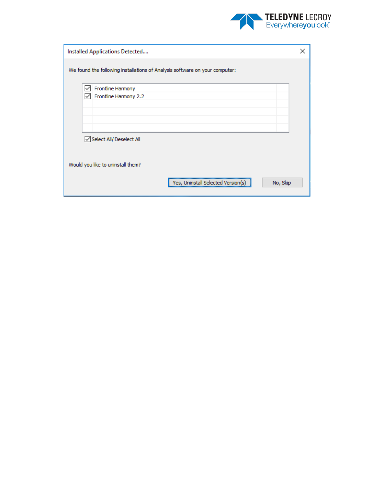
Figure 1.1 – Installed Applications Detected
Frontline Harmony Hardware & Software User Manual 7
Page 8
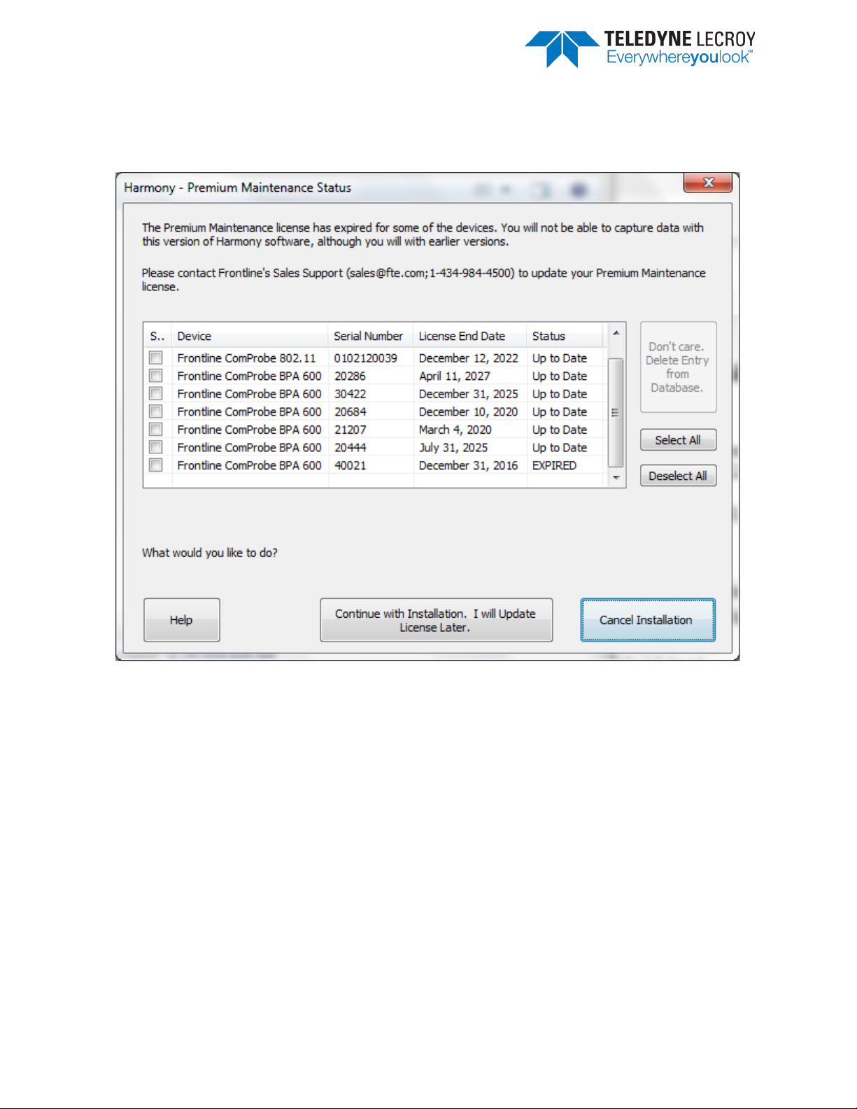
Note: If the user had previously installed Frontline hardware (such as BPA500 or BPA600) and the
Premium Maintenance for the devices have expired the following pop-up will appear and the pop-up
shown above will not be displayed during the installation of the Harmony software.
Figure 1.2 – Harmony Premium Maintenance Status
1.3 Harmony Firmware
The Harmony software will check the version of Harmony hardware firmware and determine if the
firmware needs to be upgraded or downgraded. If the firmware needs to be changed a popup window
like the one below will appear (Figure 1.3)
Frontline Harmony Hardware & Software User Manual 8
Page 9
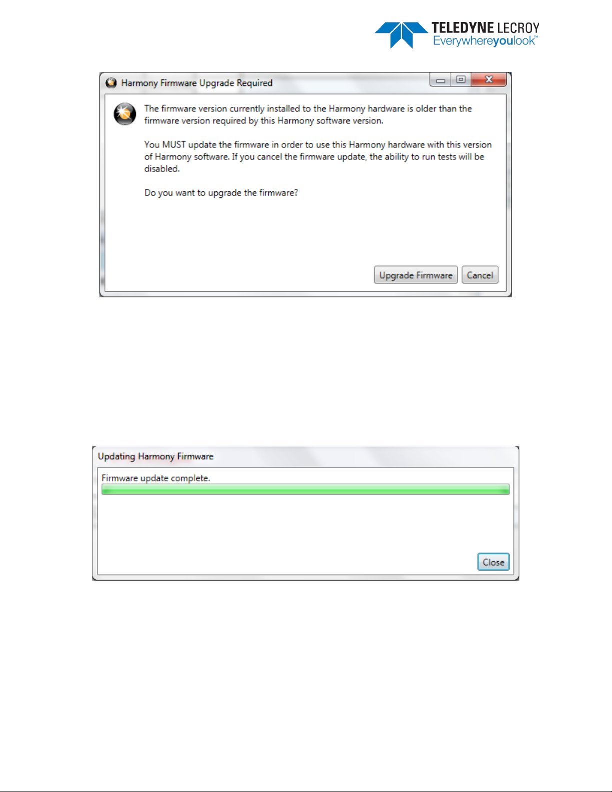
Figure 1.3 – Harmony Firmware Upgrade Notification
Follow the instructions in the popup window. Note: if the “Cancel” button is selected the firmware will
not be changed and the tests will not be run until the firmware is correct. If the firmware was not
changed when initially prompted one can change the firmware by going to Help > Update Harmony
Firmware…
If the “Upgrade Firmware” button or “Downgrade Firmware” button is clicked, another popup window
will open showing the progress of the firmware change (Figure 1.4). When the firmware change is
complete click the “Close” button.
Figure 1.4 – Updating Harmony Firmware
1.4 Sodera Firmware
The Harmony software will check the version of Sodera hardware firmware and determine if the
firmware needs to be upgraded or downgraded. If the firmware needs to be updated a popup window
like the one below will appear (Figure 1.5).
Frontline Harmony Hardware & Software User Manual 9
Page 10
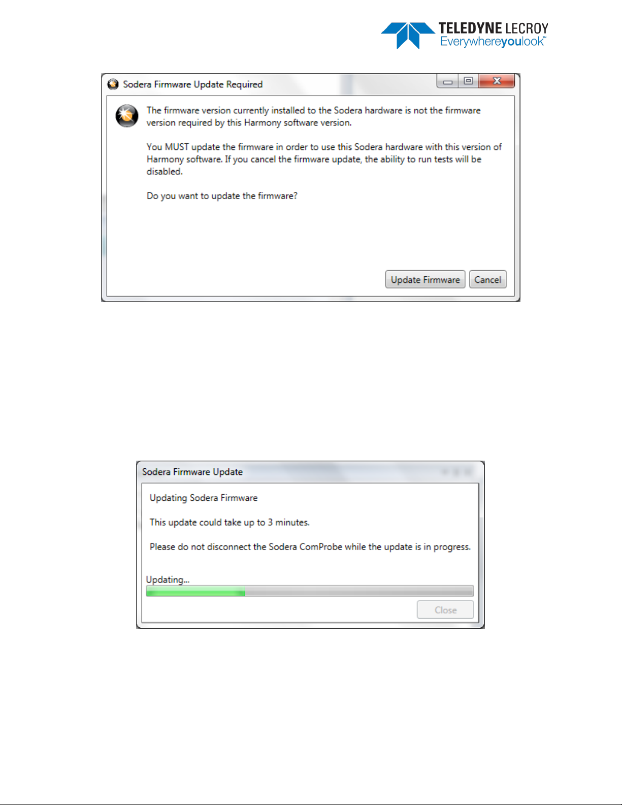
Figure 1.5 – Sodera Firmware Update Notification
Follow the instructions in the popup window. Note: if the “Cancel” button is selected the firmware will
not be changed and the tests will not be run until the firmware is correct. If the firmware was not
changed when initially prompted one can change the firmware by going to Help > Update Sodera
Firmware…
If the “Update Firmware” button is clicked, another popup window will open showing the progress of
the firmware change (Figure 1.6). When the firmware change is complete click the “Close” button.
Figure 1.6 – Sodera Firmware Update in Progress
Frontline Harmony Hardware & Software User Manual 10
Page 11
Chapter 2. Getting Started
In this chapter we introduce you to the Frontline Harmony hardware and show how to start the
Frontline Harmony software and explain the basic software controls and features for conducting
validation tests.
2.1 Harmony Hardware
2.1.1 Attaching Cables for Conductive Operation
Since over-the-air sniffing can be compromised in noisy RF environments, conductive testing is the
recommended approach.
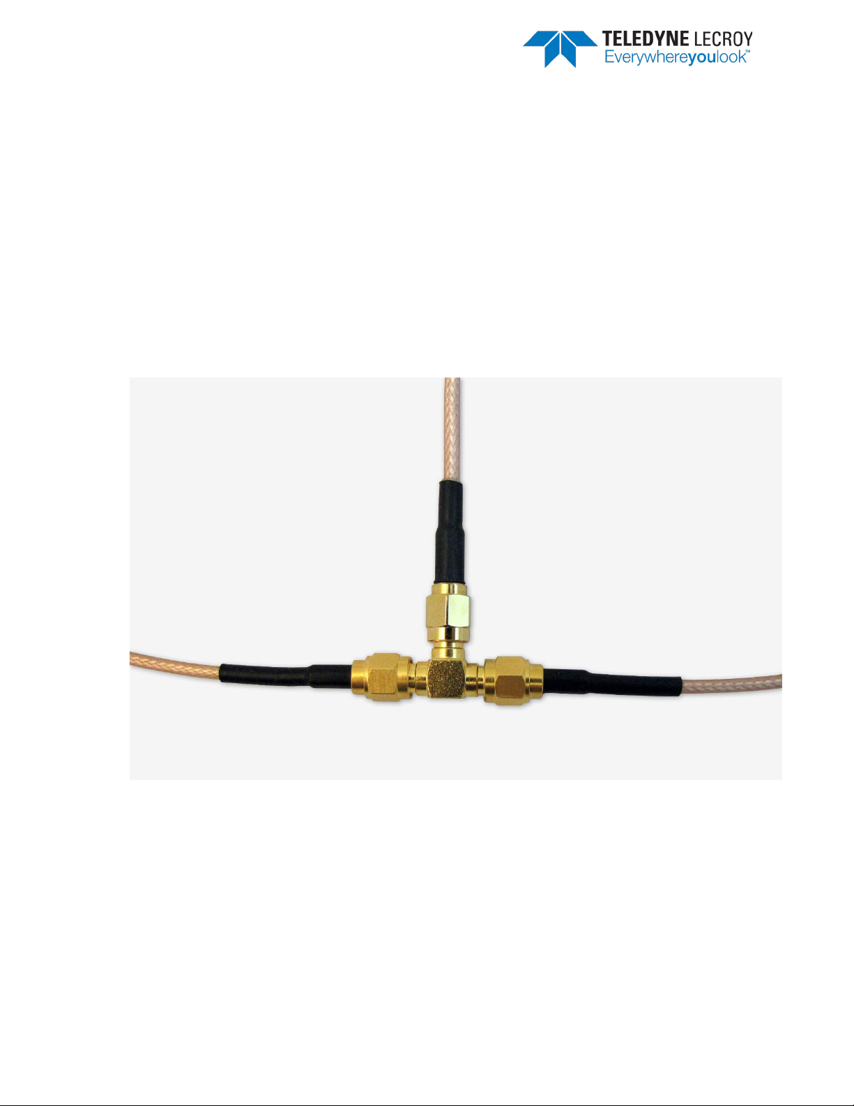
1. Attach one end of each of the three provided RF cables to the T-connector, also provided with
your Harmony Test System (Figure 2.1).
Figure 2.1 – RF Cables and T-Connector
2. To the other end of each RF cable, connect one of the three provided 20dB attenuators (Figure
2.2).
Frontline Harmony Hardware & Software User Manual 11
Page 12
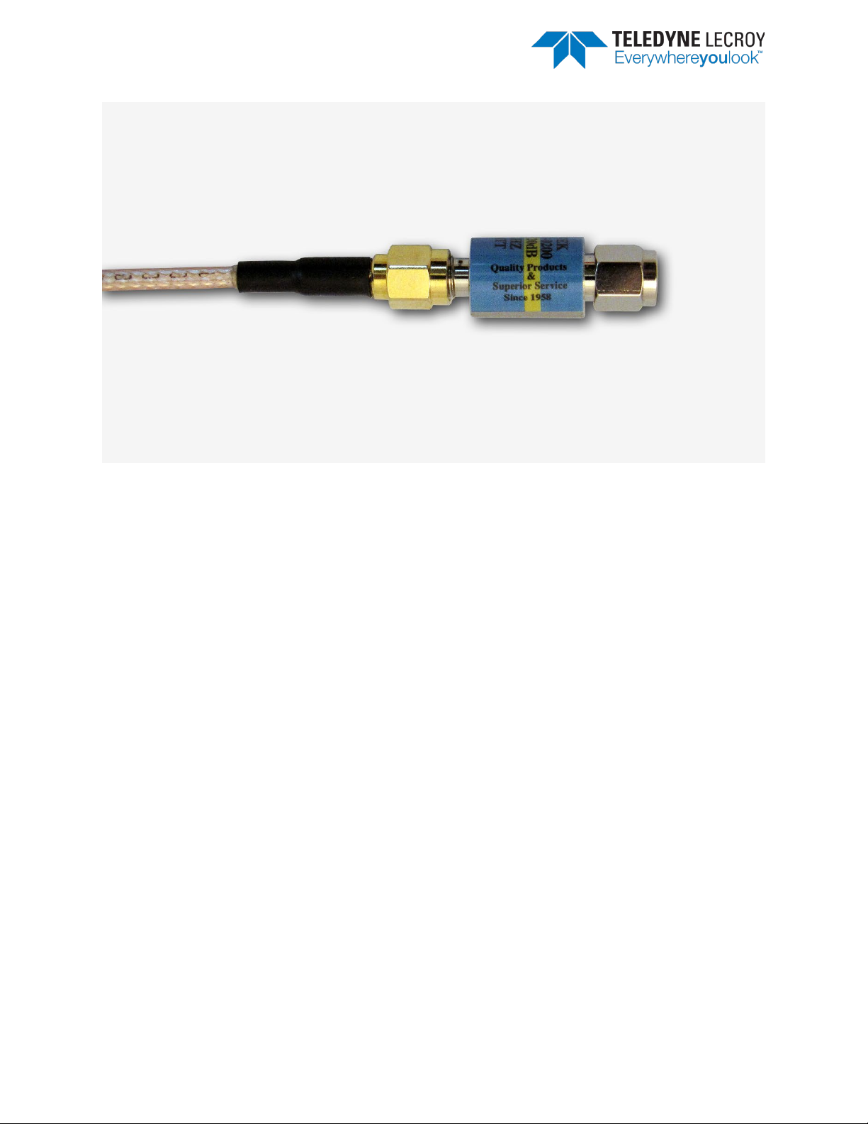
Figure 2.2 – RF Cable and Attenuator
3. Attach one cable-connected attenuator to the Antenna (ANT) port of the Harmony hardware.
4. Attach one cable-connected attenuator to the Antenna port of the Frontline Sodera hardware.
5. Attach the last cable-connected attenuator to the RF output of the IUT.
Important note: If the IUT’s RF output isn’t capacitively coupled, attach the provided DC
blocker to the attenuator before connecting the attenuator to the RF output of the IUT (Figure
2.3). If you don’t know whether the IUT’s RF output is capacitively coupled, use of the DC
blocker is recommended.
Frontline Harmony Hardware & Software User Manual 12
Page 13
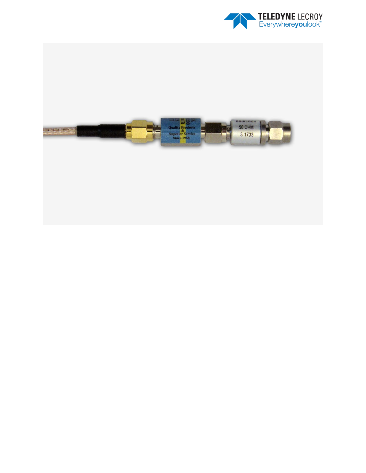
Figure 2.3 – DC Blocker Connection to Attenuator
2.1.2 Attaching Antenna for Over-the-Air Operation
Although conductive testing will yield the best results, over-the-air testing can provide good results
when the testing is done in a controlled RF environment (e.g. an RF shielded room). If you choose to do
over-the-air testing, attach the supplied antenna to the Harmony hardware.
1. Attach the antenna to the SMA connector jack under the “ANT” label. (Figure 2.4)
Frontline Harmony Hardware & Software User Manual 13
Page 14
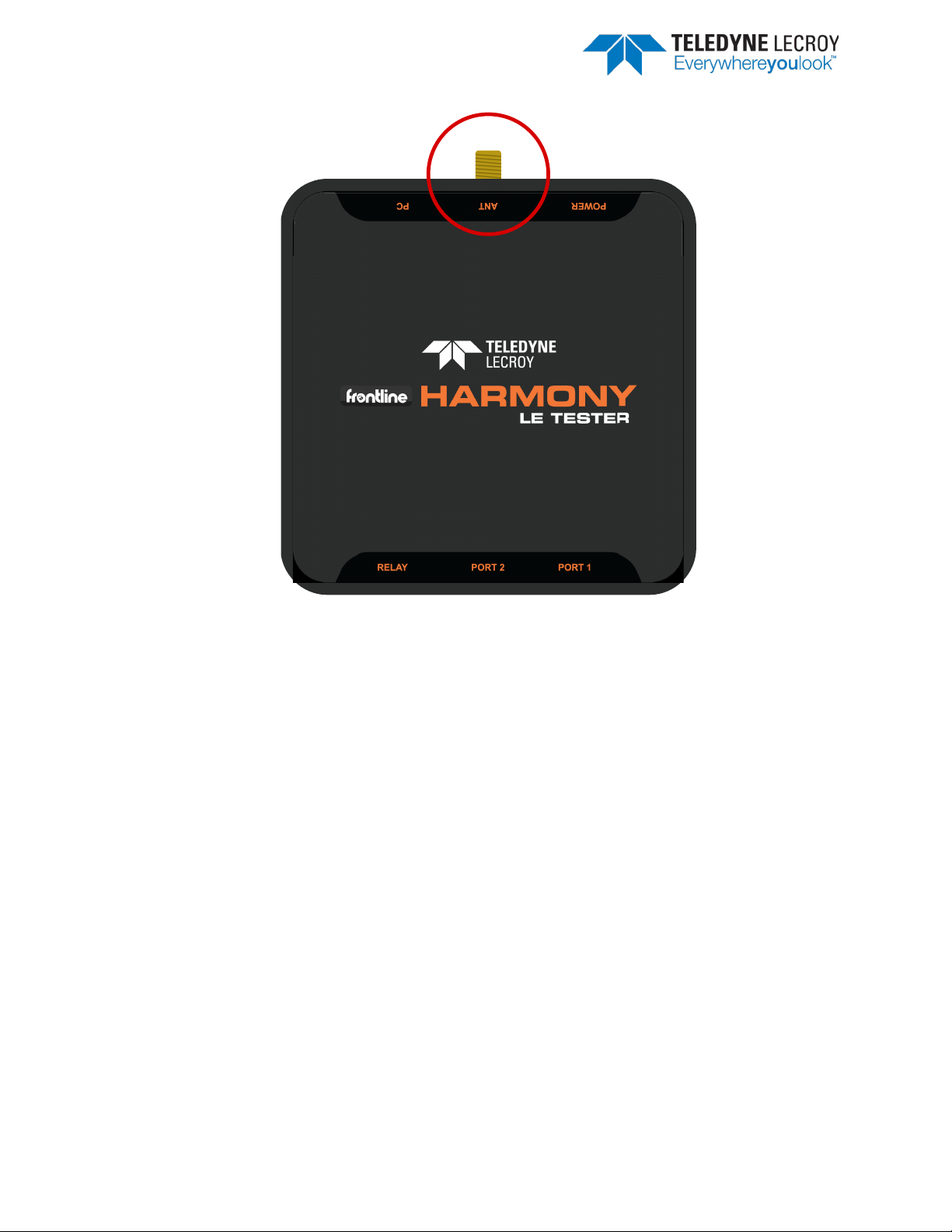
Figure 2.4 – Antenna Connection
2.1.3 Connecting/Powering the Frontline Harmony
Once you have readied the Harmony hardware for conductive or over-the-air testing, the next step is to
power up and connect the Frontline Harmony to the computer.
1. Connect the provided 5VDC 1.2A adapter to the Power port on the Frontline Harmony back
panel (Figure 2.5).
Frontline Harmony Hardware & Software User Manual 14
Page 15
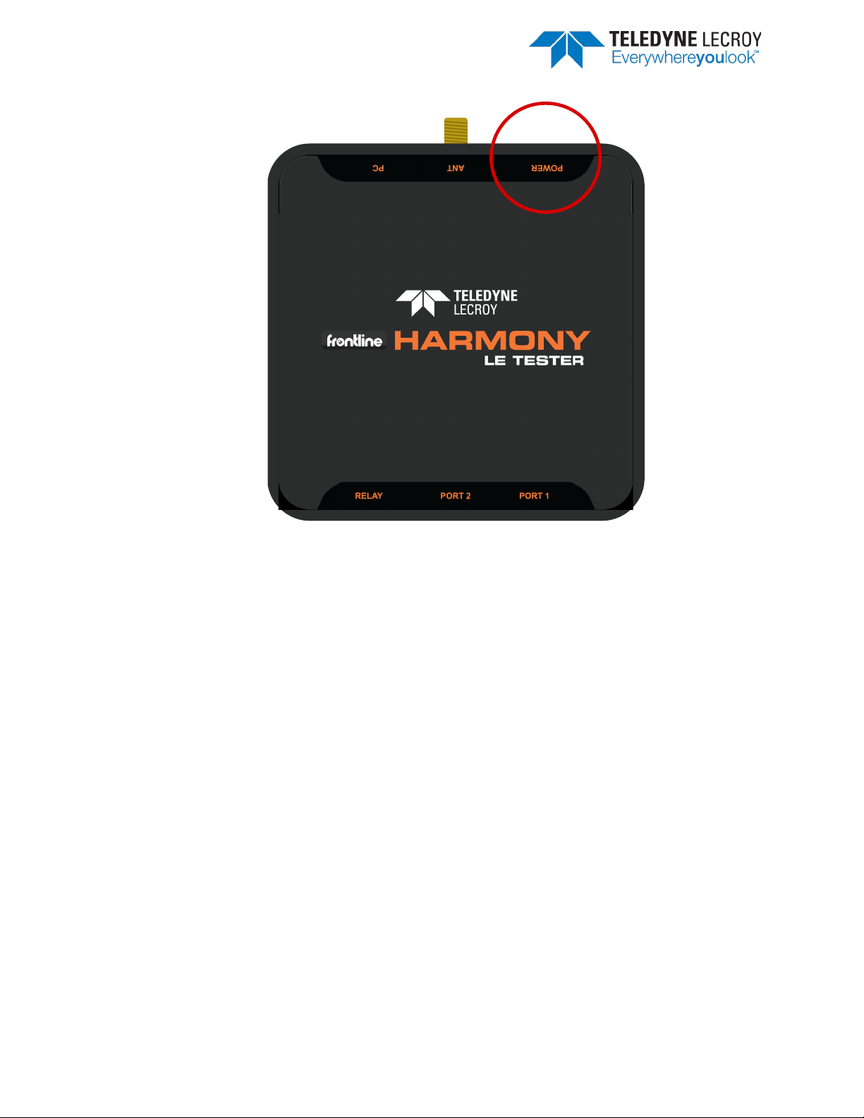
Figure 2.5 – Power Connection
2. Plug the adapter into the AC power source. The rear panel Power light will illuminate.
Note: The Harmony hardware is designed to operate using only USB power in mobile settings, or
when access to a wall outlet is unavailable. Powering your Harmony hardware using a wall
outlet will provide more power to the USB ports.
3. Insert the supplied USB mini cable into the PC connection on the Frontline Harmony rear panel
(Figure 2.6).
Frontline Harmony Hardware & Software User Manual 15
Page 16

Figure 2.6 – PC Connection
4. Insert the other end of the USB cable into the PC.
5. Insert the supplied USB mini cable into the Port 1 connection on the Frontline Harmony rear
panel (Figure 2.7). The second port is present to allow for possible future expansion.
Frontline Harmony Hardware & Software User Manual 16
Page 17
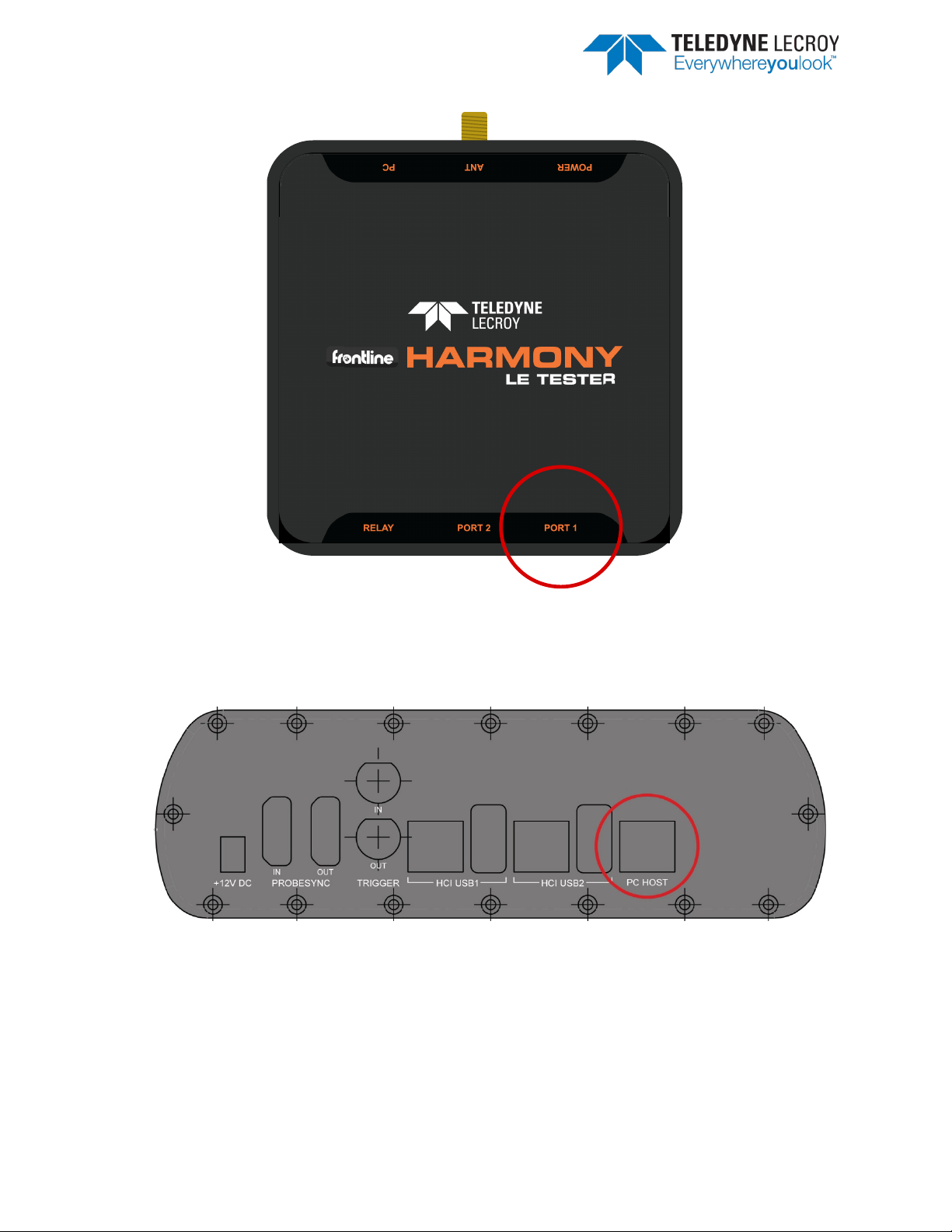
Figure 2.7 – IUT Port Connections
6. Plug the other end of the Port USB cable into the IUT.
7. Connect Frontline Sodera’s PC Host port to PC via USB (Figure 2.8)
Figure 2.8 – Sodera PC Connection
Important note: The Harmony Test System includes a Frontline Sodera unit. Other Sodera units can
be used with the Harmony hardware, however they must have either a Dual Mode Advance license
or a Single Mode LE Advance license to work correctly with the system. Please use the “Renew PM”
application to check your license type. The Sodera unit you received with the Harmony Test System
is ensured to work correctly when used in tandem with your system’s Harmony hardware.
Frontline Harmony Hardware & Software User Manual 17
Page 18
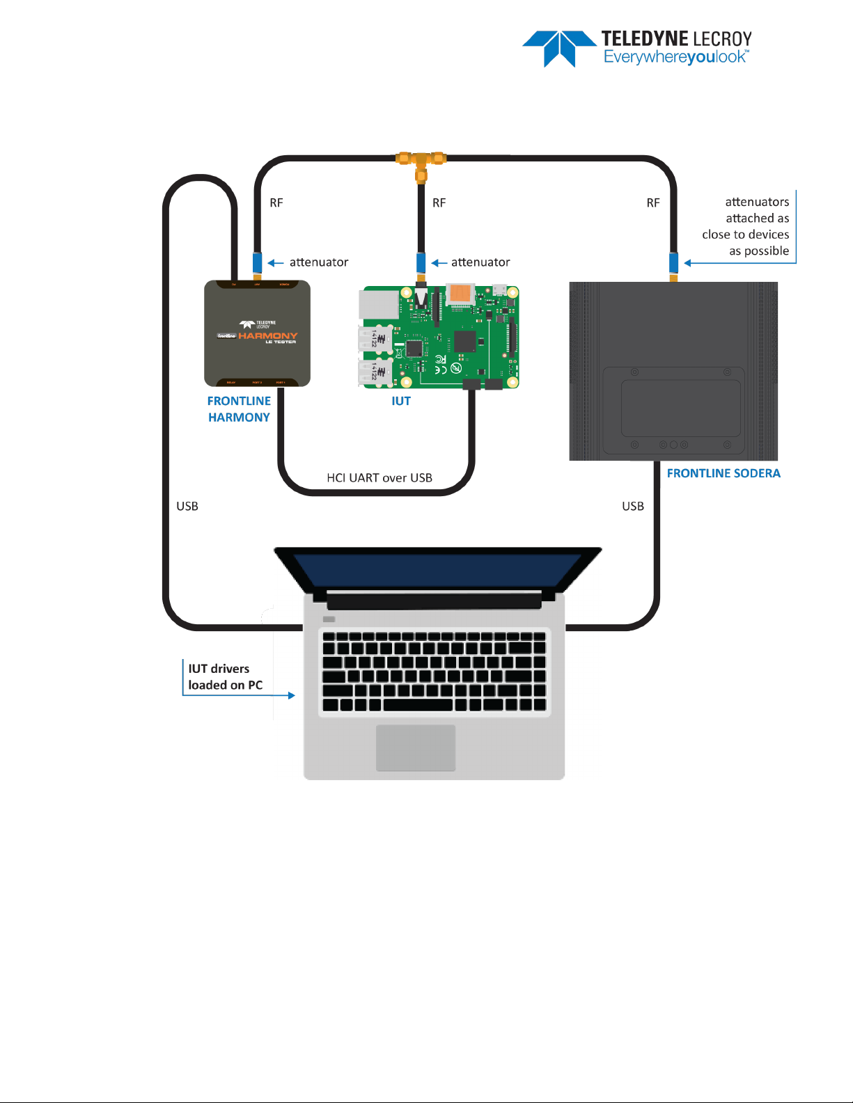
8. After making these connections, your setup should resemble a typical testing configuration
(Figure 2.9)
Figure 2.9 – Typical Testing Configuration
Frontline Harmony Hardware & Software User Manual 18
Page 19

Figure 2.10 – Relay Connections
9. The relay (Figure 2.10) port is a solid state device used to externally control devices, like
switches, triggers, etc.
a. The center pin of the connector is Common (COM) and the other two pins are Normally
Open (NO) and Normally Closed (NC).
b. The relay provides a means by which users can reset their IUT between tests (e.g. by
removing and then reapplying power to the IUT, or by asserting & releasing a reset line).
2.1.4 Launching the Software
Installing the Frontline Harmony software creates folders necessary for the operation of the software.
After you’ve placed the “licenseKey.py” license key in the appropriate folder per section 1.3, you can
launch the software using one of two methods.
1. Click the Windows Start Menu, then under All Programs find the Frontline Harmony program
group and click on “Harmony Tester.”
2. Open the Frontline Harmony Folder that was added during installation to your desktop and click
on “Harmony Tester.”
3. The Harmony Tester interface is comprised of eight panes (Figure 2.11)
a. Test Selection – allows you to select tests to run
b. Run Explorer – allows you to review tests that have already been completed
Frontline Harmony Hardware & Software User Manual 19
Page 20

c. Event Viewer – the Event Viewer is a record of significant events that occurred at any
time the Harmony LE Tester is running
d. Project Settings – provides test settings
e. Tester and IUT Configuration – provides for configuration of Harmony hardware and IUT
hardware
f. IXIT Data – provides for Implementation eXtra Information for Test (Implementation-
specific values that further describe the capabilities of the IUT, e.g. the limits of what is
supported).
g. IUT Information – provides for customer, manufacturer and product information
h. Test Results – provides pass/fail feedback on tests run
Figure 2.11 – Harmony Tester Interface
Frontline Harmony Hardware & Software User Manual 20
Page 21

Chapter 3. Configuration Settings
In this chapter we describe the configurations required for the best testing results using the Frontline
Harmony.
3.1 Configuring the Software
3.1.1 Project Settings
Click the “Project Settings” tab to configure basic project settings. (Figure 3.1)
Figure 3.1 – Project Settings Configuration
1. Use the drop down box next to “Max. Number of Test Retries” to the desired number. The
Harmony software allows 0-9 automatic test retries to allow for noise interference or other
hard to control environmental factors.
2. The Results Path will remain unspecified until you save your project, at which time you will
name the location of your project files, specify a project name, and add a project
description. (Figure 3.2)
Frontline Harmony Hardware & Software User Manual 21
Page 22

Figure 3.2 – Create a New Project Dialog
3. Clicking “OK” saves the project files into the specified location. If the specified folder does
not already exist, the Harmony software creates the folder.
3.1.2 Tester and IUT Configuration
Click the “Tester and IUT Configuration” tab to configure settings affecting the Harmony tester, PC
connection, and the IUT. (Figure 3.3)
Frontline Harmony Hardware & Software User Manual 22
Page 23

Figure 3.3 – Tester and IUT Configuration
1. If the Harmony hardware is connected, the BD ADDR of the Harmony and the port that the
Harmony is connected to will be displayed.
2. Connect the IUT.
3. Under IUT Configuration, set Device Type to Generic UART.
4. The BD ADDR of the IUT will remain blank until testing is started. Once testing has started
the BD ADDR for the IUT will be filled in automatically.
5. Select the correct PORT for the IUT to enable a connection to the IUT.
6. Select the correct Baud Rate for the IUT.
7. Select the correct Flow Control for the IUT.
8. Select the preferred method for resetting the IUT between test cases:
a. HCI Reset – this setting will allow the Harmony tester to send an HCI reset command
to the IUT
b. Power Cycle – this setting will allow the Harmony tester to shut off power to the
USB port and toggle the relay for a configurable number of seconds. Note: The “Off
Seconds” textbox will be enabled when “Power Cycle” is selected.
9. Click the “IUT Supported Commands” button to populate the octet fields. Note: It is
important to fill in the octet fields otherwise some tests will fail.
Frontline Harmony Hardware & Software User Manual 23
Page 24

3.1.3 IXIT Data
Click the “IXIT Data” tab to configure device and advertising information that may be required by certain
Bluetooth SIG specified test cases. (Figure 3.4)
Figure 3.4 – IXIT Data
3.1.4 IUT Information
Click the “IUT Information” tab to configure customer, manufacturer and product meta data. Some
fields are required so that any Test Reports produced include the information expected in a Bluetooth
validation report. (Figure 3.5)
Frontline Harmony Hardware & Software User Manual 24
Page 25

Figure 3.5 – IUT Information
Frontline Harmony Hardware & Software User Manual 25
Page 26

Chapter 4. Running Tests
Test
Description Summary
HCI/AEN/BI-01-C
Verify that the IUT can return an error when invalid public keys is received.
HCI/AEN/BV-06-C
Verify that the IUT can generate a P-256 Public-Private key pair and return
the P-256 Public Key
HCI/AEN/BV-07-C
Verify that the IUT can generate a new Diffie-Hellman Key
HCI/AEN/BV-08-C
Generate Debug Keys
HCI/CCO/BV-07-C
Verify that an IUT which supports LE only, does not respond to BR/EDR HCI
commands
HCI/CCO/BV-09-C
Verify that the IUT correctly handles the LE Set Data Length Command
HCI/CCO/BV-10-C
Verify that the IUT correctly handles the LE Read Suggested Data Length
Command
HCI/CCO/BV-11-C
Verify that the IUT correctly handles the LE Write Suggested Data Length
Command
HCI/CCO/BV-12-C
Verify that the IUT correctly handles the LE Remove Device From Resolving
List Command
HCI/CCO/BV-13-C
Verify that the IUT correctly handles the LE Clear Resolving List Command
Harmony software allows you to run one, multiple or all Link Layer and HCI tests provided. (Figure 4.1)
Figure 4.1 – Running Tests
4.1 Selecting Tests
4.1.1 HCI
The Harmony software provides 45 HCI tests (Table 4.1). To run HCI tests, expand the HCI Test Suite to
select one or more specific tests, or you may select Test Suite – HCI to run all HCI tests.
Table 4.1 – HCI Tests
Frontline Harmony Hardware & Software User Manual 26
Page 27

HCI/CCO/BV-14-C
Verify that the IUT correctly handles the LE Read Resolving List Size
Command
HCI/CCO/BV-15-C
Verify that the IUT correctly handles the LE Set Default PHY Command
HCI/CCO/BV-16-C
Verify that the IUT correctly handles the LE Read Periodic Advertiser List Size
Command
HCI/CCO/BV-17-C
Verify that the IUT correctly handles the LE Add Device To Periodic
Advertiser List, LE Remove Device From Periodic Advertiser List, and Clear
Periodic Advertiser List commands
HCI/CCO/BV-18-C
Verify that the IUT correctly handles the LE Read Transmit Power Command
HCI/CCO/BV-19-C
Verify that the IUT correctly handles the LE Write RF Path Compensation
Command
HCI/CCO/BV-20-C
Verify that the IUT correctly handles the LE Read RF Path Compensation
Command
HCI/CFC/BV-02-C
Buffer Size
HCI/CIN/BV-01-C
Verify that the Read Local Supported Features command returns with the
correct features supported
HCI/CIN/BV-03-C
Read Local Supported Commands
HCI/CIN/BV-04-C
Read Local Version Information
HCI/CIN/BV-06-C
White List Size
HCI/CIN/BV-09-C
Verify that the LE Read Local Supported Features command returns with the
Remote Public Key Validation feature bit enabled.
HCI/CM/BV-01-C
LE Read Peer Resolvable Address Command – Master
HCI/CM/BV-02-C
LE Read Local Resolvable Address Command – Master
HCI/CM/BV-03-C
Verify that the IUT correctly handles the LE Read PHY Command
HCI/CM/BV-04-C
Tests that when the IUT is initiator and an RPA Timeout occurs between the
Local_Resolvable_Private_Address sent and received over the air.
HCI/CM/BV-05-C
LE Read Peer Resolvable Address Command – Slave
HCI/CM/BV-06-C
LE Read Local Resolvable Address Command - Slave
HCI/DDI/BI-01-C
Verify that the IUT properly rejects an invalid advertising interval provided to
the expected error code
HCI/DDI/BI-02-C
Verify that the IUT properly rejects an invalid advertising interval provided to
error code
HCI/DDI/BI-03-C
Reject LE Periodic Advertising Create Sync Command With Disallowed
Reporting Options
HCI/DDI/BI-04-C
Reject LE Periodic Advertising Create Sync Command to a Synchronized
Advertising Set
HCI/DDI/BV-03-C
Set Advertise Enable
HCI/DDI/BV-04-C
Set Scan Enable
HCI/DSU/BV-02-C
Reset in advertising state
HCI/DSU/BV-03-C
Reset to slave
HCI/DSU/BV-04-C
Reset in scanning state
IUT issuing an AUX_CONNECT_REQ PDU and the Lower Tester responding
with an AUX_CONNECT_RSP PDU, that the
HCI_LE_Enhanced_Connection_Complete_Event returns the latest
Peer_Address, Peer_Resolvable_Private_Address and
the HCI_LE_Set_Extended_Advertising_Parameters command and returns
the HCI_LE_Set_Advertising_Parameters command and returns the expected
Frontline Harmony Hardware & Software User Manual 27
Page 28

HCI/DSU/BV-05-C
Reset in initiating state
HCI/DSU/BV-06-C
Reset to master
HCI/GEV/BV-01-C
Verify that for each controller supported in the IUT, every HCI command not
supported yields a Command Complete event with status Unknown HCI
Command in return
HCI/GEV/BV-02-C
Verify that each supported legacy and extended scanning command yields a
sent after a command of the other type
HCI/GEV/BV-03-C
Verify that each supported legacy and extended scanning command yields a
when sent after a command of the other type
HCI/GEV/BV-04-C
Verify that each specified extended advertising command yields a Command
no scan response data
HCI/HFC/BV-04-C
LE Set Event Mask
Test
Description Summary
LL/CON/ADV/BI-01-C
Connection Supervision Timeout During Fail Connection Setup
LL/CON/ADV/BV-01-C
Accepting Connections
LL/CON/ADV/BV-02-C
Accepting Connections Timeout
LL/CON/ADV/BV-03-C
ADVERTISING/MASTER - Master Packets
LL/CON/ADV/BV-04-C
Tests that an advertiser IUT upon receiving a connection indication to the
starts to maintain a connection in the slave role
LL/CON/ADV/BV-05-C
Extended Advertising, Accepting Connections – LE 1M PHY
LL/CON/ADV/BV-06-C
Tests that an advertiser IUT using undirected connectable advertising with
slave role
LL/CON/ADV/BV-07-C
Tests that an advertiser IUT receives a connection request stops advertising
Algorithm #2
LL/CON/ADV/BV-08-C
Tests that an advertiser IUT receives a connection request to the directing
indicates no support for Channel Selection Algorithm #2
LL/CON/ADV/BV-09-C
Tests that an advertiser IUT receives a connection request stops advertising
after the reception and starts to maintain a connection in the slave role
command complete event with status 'Command Disallowed' in return when
Command Complete event with status ‘Command Disallowed’ in return
Complete event with status ‘Command Disallowed’ in return when sent with
4.1.2 Link Layer
The Harmony software provides 484 Link Layer tests (Table 4.2). To run LL tests, expand the LL Test
Suite to select one or more specific tests, or you may select Test Suite – LL to run all Link Layer tests.
Table 4.2 – Link Layer Tests
directed advertising indications stops advertising after the reception and
legacy PDUs receives a connection indication on the primary channel stops
advertising after the reception and starts to maintain a connection in the
after the reception and starts to maintain a connection in the slave role
when the connection request indicates no support for Channel Selection
advertising indication stops advertising after the reception and starts to
maintain a connection in the slave role when the connection request
Frontline Harmony Hardware & Software User Manual 28
Page 29

when the connection request indicates support for Channel Selection
Algorithm #2
LL/CON/ADV/BV-10-C
Tests that an advertiser IUT receives a connection request to the directing
advertising indication stops advertising after the reception and starts to
indicates support for Channel Selection Algorithm #2
LL/CON/ADV/BV-11-C
Accepting Connections, IUT Channel Selection Algorithm #1, Lower Tester
Channel Selection Algorithm #2
LL/CON/ADV/BV-12-C
Extended Advertising, Accepting Connections – LE 2M PHY
LL/CON/ADV/BV-13-C
Extended Advertising, Accepting Connections – LE Coded PHY
LL/CON/INI/BI-01-C
Tests that an initiator IUT ignores advertising packets with an invalid
checksum
LL/CON/INI/BI-02-C
Tests that an initiator IUT sends a connection indication to an advertiser
connection failed
LL/CON/INI/BV-01-C
Tests that an initiator IUT sends a connection indication to an advertiser
and starts to maintain a connection in the master role
LL/CON/INI/BV-02-C
Tests that an initiator IUT sends a connection indication to an advertiser
master role
LL/CON/INI/BV-03-C
Tests that an initiator IUT sends a connection indication to an advertiser
scenario which the IUT must manage
LL/CON/INI/BV-04-C
Connection Initiation Timeout
LL/CON/INI/BV-06-C
Initiation Device Filtering: Undirected
LL/CON/INI/BV-07-C
Initiation Device Filtering: Directed
LL/CON/INI/BV-08-C
LE Set Address Resolution Enable Command - Initiator
LL/CON/INI/BV-09-C
Verify that the IUT when init conn est only connect to devices that are in
the RL
LL/CON/INI/BV-10-C
Verify that the IUT when init conn est with the RL conn only to peer devs
that are in the RL
LL/CON/INI/BV-11-C
Verify that the IUT when initiating connection establishment with the
to the IUT
LL/CON/INI/BV-12-C
Verify that the IUT when init private connection establishment with the RL
does not conn to direct that are addressed to the IUT using its ID addr
LL/CON/INI/BV-13-C
Extended Scanning, Connection Initiation – LE 1M PHY
LL/CON/INI/BV-14-C
Tests that an initiator IUT sends a connection request to an advertiser and
indicates no support of Channel Selection Algorithm #2
LL/CON/INI/BV-15-C
Tests that an initiator IUT sends a connection request to an advertiser using
Algorithm #2
maintain a connection in the slave role when the connection request
and receiving reply transmissions with invalid checksums from the slave up
to the point of expiring the connection supervision timer considers the
using directed advertising events and starts to maintain a connection in the
and after missing some reply transmissions from the slave still manages to
setup a connection in the master role. This test purpose reflects a typical
resolving list connects only to directed advertisements that are addressed
starts to maintain a connection in the master role when the advertisement
directed advertising and starts to maintain a connection in the master role
when the advertisement indicates no support of Channel Selection
Frontline Harmony Hardware & Software User Manual 29
Page 30

LL/CON/INI/BV-16-C
Tests that an initiator IUT sends a connection request to an advertiser and
starts to maintain a connection in the master role when the advertisement
indicates support of Channel Selection Algorithm #2
LL/CON/INI/BV-17-C
Tests that an initiator IUT sends a connection request to an advertiser using
#2
LL/CON/INI/BV-18-C
Verify that the IUT when initiating connection establishment does not
network privacy mode
LL/CON/INI/BV-19-C
Verify that the IUT when initiating connection establishment does not
network privacy mode
LL/CON/INI/BV-20-C
Verify that the IUT when initiating connection establishment connects to a
mode
LL/CON/INI/BV-21-C
Verify that the IUT when initiating connection establishment connects to a
mode
LL/CON/INI/BV-22-C
Tests that an initiator IUT that only supports Channel Selection Algorithm
connection.
LL/CON/INI/BV-23-C
Network Privacy - Connection Establishment using whitelist and resolving
list with address resolution disabled
LL/CON/INI/BV-24-C
Network Privacy - Connection Establishment using resolving list with
address resolution disabled
LL/CON/INI/BV-25-C
Extended Scanning, Connection Initiation – LE 2M PHY
LL/CON/INI/BV-26-C
Extended Scanning, Connection Initiation – LE Coded PHY
LL/CON/MAS/BI-02-C
Master T_Terminate Timer
LL/CON/MAS/BI-04-C
Test that a slave device is able to recover from a control procedure failure
LL/CON/MAS/BI-05-C
MASTER - Initiating Connection Parameter Request - Timeout
LL/CON/MAS/BI-06-C
Accepting Connection Parameter Request - Illegal Parameters
LL/CON/MAS/BV-02-C
Test that a master IUT is able to maintain a connection when the slave using
the slave latency mechanism
LL/CON/MAS/BV-03-C
Master Sending Data
LL/CON/MAS/BV-04-C
MASTER - Master Receiving Data
LL/CON/MAS/BV-05-C
MASTER - Master Sending And Receiving Data
directed advertising and starts to maintain a connection in the master role
when the advertisement indicates support of Channel Selection Algorithm
connect to a device advertising using its device identity address when the
identity address and an associated IRK are in the resolving list using
connect to a device advertising using its device identity address when the
identity address and an associated IRK are in the resolving list using
device advertising using its device identity address when the identity
address and an associated IRK are in the resolving list using device privacy
device advertising using its device identity address when the identity
address and an associated IRK are in the resolving list using device privacy
#1 sends a connection request to an advertiser and starts to maintain a
connection in the master role when the advertisement indicates support of
Channel Selection Algorithm #2. The Lower Tester first acts in the
advertising state with ChSel set to one (1), then accepts the connection and
starts to maintain it in the slave role, observing the packet and timing from
the IUT. The IUT confirms the Channel Selection Algorithm #1 is used for the
Frontline Harmony Hardware & Software User Manual 30
Page 31

LL/CON/MAS/BV-07-C
Requesting Parameter Update
LL/CON/MAS/BV-08-C
Master Sending Termination
LL/CON/MAS/BV-09-C
Master Accepting Termination
LL/CON/MAS/BV-10-C
Test that a master IUT terminates a connection by the supervision timer
LL/CON/MAS/BV-13-C
MASTER - Feature Setup Request
LL/CON/MAS/BV-14-C
Test that a master IUT is able to maintain a connection using the
acknowledgement scheme and retransmit
LL/CON/MAS/BV-15-C
Test that a master IUT is able to maintain a connection using the
acknowledgement scheme and retransmit a data packet on a negative
acknowledgement
LL/CON/MAS/BV-16-C
Test that a master IUT is able to maintain a connection using the
packet
LL/CON/MAS/BV-17-C
Test that a master IUT is able to maintain a connection using the
the case of a lost negative acknowledgement
LL/CON/MAS/BV-18-C
Test that a master IUT is able to maintain a connection using the
acknowledgement scheme with the slave using latency
LL/CON/MAS/BV-19-C
Connection Control Timeout
LL/CON/MAS/BV-20-C
Master Request Version
LL/CON/MAS/BV-21-C
Test that a connected master IUT responds to the request from the Tester
to perform the version exchange procedure
LL/CON/MAS/BV-22-C
MASTER - Master Acknowledgement Scheme
LL/CON/MAS/BV-23-C
MASTER - Responding to Feature Exchange
LL/CON/MAS/BV-24-C
MASTER - Initiating Connection Parameter Request - Accept
LL/CON/MAS/BV-25-C
MASTER - Initiating Connection Parameter Request - Reject
LL/CON/MAS/BV-26-C
Initiating Connection Parameter Request - Same Procedure Collision
LL/CON/MAS/BV-27-C
Initiating Connection Parameter Request - Different Procedure Collision Channel Map Update
LL/CON/MAS/BV-28-C
Initiating Connection Parameter Request - Different Procedure Collision Encryption
LL/CON/MAS/BV-29-C
MASTER - Initiating Connection Parameter Request - Remote Legacy Host
LL/CON/MAS/BV-30-C
Accepting Connection Parameter Request - No Preferred Periodicity
LL/CON/MAS/BV-31-C
Accepting Connection Parameter Request - Preferred Anchor Points Only
LL/CON/MAS/BV-32-C
Accepting Connection Parameter Request - Preferred Periodicity
LL/CON/MAS/BV-33-C
Accepting Connection Parameter Request - Preferred Periodicity and
Preferred Anchor Points
LL/CON/MAS/BV-34-C
MASTER - Accepting Connection Parameter Request - Event Masked
LL/CON/MAS/BV-35-C
MASTER - Accepting Connection Parameter Request - Host Rejects
LL/CON/MAS/BV-41-C
Test that a master IUT is able to perform the PHY update procedure
LL/CON/MAS/BV-42-C
Test that a master IUT is able to perform the PHY update procedure when
asymmetric links are not supported
LL/CON/MAS/BV-43-C
Test that a master IUT is able to respond to a PHY update procedure from a
slave device
acknowledgement scheme and repeats a positive acknowledgement of a
acknowledgement scheme and preserve the packet sequence numbering in
Frontline Harmony Hardware & Software User Manual 31
Page 32

LL/CON/MAS/BV-44-C
Test that a master IUT is able to respond to a PHY update procedure from a
slave device when asymmetric links are not supported
LL/CON/MAS/BV-45-C
Test that a master IUT is able to perform the PHY update procedure when
there is a procedure collision between the IUT's PHY change request and
the remote device's PHY change request
LL/CON/MAS/BV-46-C
Test that a master IUT terminates the Link Layer connection if the master-
response timer expires
LL/CON/MAS/BV-47-C
Test that a master IUT is able to perform the channel map update
map update and the Lower Tester's PHY change request
LL/CON/MAS/BV-48-C
Test that a master IUT is able to perform the connection parameters
connection parameters request and the Lower Tester's PHY change request
LL/CON/MAS/BV-49-C
Test that a master IUT follows all packet time restrictions both during and
after PHY change when it initiates the PHY update procedure
LL/CON/MAS/BV-50-C
Test that a master IUT both during and after PHY change follows all packet
device
LL/CON/MAS/BV-51-C
Test that a master IUT correctly handles the case where it initiates a PHY
update procedure but no common PHYs are available
LL/CON/MAS/BV-52-C
Test that a master IUT is able to receive data from a slave device when the
required
LL/CON/MAS/BV-53-C
Test that a master IUT follows all packet time restrictions both during and
for retransmission after the PHY Update instant
LL/CON/MAS/BV-54-C
Test that a master IUT both during and after PHY update when it responds
retransmission after the PHY Update instant
LL/CON/MAS/BV-55-C
Test that a master IUT still transmits data even when the TxTime and/or
the minimum length data PDU (27 octets)
LL/CON/MAS/BV-56-C
Constant Tone Extension Request Procedure, IUT Initiated, AoA – LE 1M
PHY
LL/CON/MAS/BV-57-C
Constant Tone Extension Request Procedure, IUT Initiated, Periodic
LL/CON/MAS/BV-58-C
Constant Tone Extension Request Procedure, IUT Initiated, Responses
Disabled
LL/CON/MAS/BV-59-C
Verifies that the IUT correctly handles the case where the remote does not
support the Connection CTE Response feature.
initiated PHY update procedure is not completed before the procedure
procedure when there is a procedure collision between the IUT's channel
request procedure when there is a procedure collision between the IUT's
time restrictions when it responds to a PHY update procedure from a slave
slave is transitioning between 125kbit and 500kbit coded rates. Confirm
that IUT responds within the allowed T_IFS times for each packet at either
coded rate. Test is performed with the IUT's minimum and maximum
supported packet length. A Data Length Update Procedure is performed if
after PHY update when it initiates the PHY Update Procedure. In particular
test that the IUT does not queue a packet for transmission that would
satisfy the requirements when queued but violate them if it is still waiting
to a PHY Update Procedure from a slave device. In particular test that the
IUT does not queue a packet for transmission that would satisfy the
requirements when queued but violate them if it is still waiting for
RxTime values for LE Coded PHY suggest a smaller possible data length than
Frontline Harmony Hardware & Software User Manual 32
Page 33

LL/CON/MAS/BV-60-C
Constant Tone Extension Request Procedure, IUT Initiated, Timeout
LL/CON/MAS/BV-61-C
Constant Tone Extension Request Procedure, IUT Responding, AoA
LL/CON/MAS/BV-62-C
Constant Tone Extension Request Procedure, IUT Responding, Responses
Disabled
LL/CON/MAS/BV-63-C
Constant Tone Extension Request Procedure, IUT Initiated, AoD – LE 1M
PHY
LL/CON/MAS/BV-64-C
Constant Tone Extension Request Procedure, IUT Responding, AoD
LL/CON/MAS/BV-65-C
Unrequested Constant Tone Extension, IUT Receiving, AoA – LE 1M PHY
LL/CON/MAS/BV-66-C
Unrequested Constant Tone Extension, IUT Receiving, AoD – LE 1M PHY
LL/CON/MAS/BV-67-C
Constant Tone Extension Request Procedure, IUT Initiated, AoA, Encrypted
Connection – LE 1M PHY
LL/CON/MAS/BV-68-C
Constant Tone Extension Request Procedure, IUT Responding, AoA,
Encrypted Connection
LL/CON/MAS/BV-69-C
Constant Tone Extension Request Procedure, IUT Initiated, AoD, Encrypted
Connection – LE 1M PHY
LL/CON/MAS/BV-70-C
Constant Tone Extension Request Procedure, IUT Responding, AoD,
Encrypted Connection
LL/CON/MAS/BV-71-C
Constant Tone Extension Request Procedure, IUT Initiated, AoA, Incorrect
CRC – LE 1M PHY
LL/CON/MAS/BV-73-C
Verify that the IUT as Master correctly handles reception of an
LL_LENGTH_REQ PDU on the LE 1M PHY
LL/CON/MAS/BV-74-C
Verify that a master IUT is able to perform the Data Length Update
Procedure by sending an LL_LENGTH_REQ PDU on the LE 1M PHY
LL/CON/MAS/BV-75-C
Verify that the IUT as Master correctly handles communication with a
Lower Tester that does not support the Data Length Update Procedure
LL/CON/MAS/BV-76-C
Verify that the IUT as Master correctly handles reception of an
LL_LENGTH_REQ PDU on the LE 2M PHY
LL/CON/MAS/BV-77-C
Verify that a master IUT is able to perform the Data Length Update
Procedure by sending an LL_LENGTH_REQ PDU on the LE 2M PHY
LL/CON/MAS/BV-78-C
Verify that the IUT as Master correctly handles reception of an
LL_LENGTH_REQ PDU on the LE Coded PHY
LL/CON/MAS/BV-79-C
Verify that a master IUT is able to perform the Data Length Update
Procedure by sending an LL_LENGTH_REQ PDU on the LE Coded PHY
LL/CON/MAS/BV-80-C
Verify that the IUT as Master correctly handles communication with a
LE Coded PHY
LL/CON/MAS/BV-81-C
Test that a master IUT is able to perform the connection parameter request
remote device does not support the request
LL/CON/MAS/BV-82-C
Test that a master IUT is able to perform the connection parameter request
not support the request
LL/CON/MAS/BV-83-C
Constant Tone Extension Request Procedure, IUT Responding, Unsupported
LL/CON/MAS/BV-84-C
Periodic Advertising Sync Transfer Procedure, Advertising IUT Initiated
LL/CON/MAS/BV-85-C
Periodic Advertising Sync Transfer Procedure, Advertising IUT Initiated
LL/CON/MAS/BV-86-C
Periodic Advertising Sync Transfer Procedure, Advertising IUT Initiated
Lower Tester that does not support the Data Length Update Procedure on
procedure when a feature exchange has not been performed and the
procedure after the feature exchange reveals that the remote device does
Frontline Harmony Hardware & Software User Manual 33
Page 34

LL/CON/MAS/BV-87-C
Periodic Advertising Sync Transfer Procedure, Advertising IUT Initiated
LL/CON/MAS/BV-88-C
Periodic Advertising Sync Transfer Procedure, Advertising IUT Initiated
LL/CON/MAS/BV-89-C
Periodic Advertising Sync Transfer Procedure, Synchronized IUT Initiated
LL/CON/MAS/BV-90-C
Periodic Advertising Sync Transfer Procedure, Synchronized IUT Initiated
LL/CON/MAS/BV-91-C
Periodic Advertising Sync Transfer Procedure, Synchronized IUT Initiated
LL/CON/MAS/BV-92-C
Periodic Advertising Sync Transfer Procedure, Synchronized IUT Initiated
LL/CON/MAS/BV-93-C
Periodic Advertising Sync Transfer Procedure, Synchronized IUT Initiated
LL/CON/MAS/BV-94-C
Periodic Advertising Sync Transfer Procedure, Accepting – Different PHYs
LL/CON/MAS/BV-95-C
Periodic Advertising Sync Transfer Procedure, Accepting – Different PHYs
LL/CON/MAS/BV-96-C
Periodic Advertising Sync Transfer Procedure, Accepting – Different PHYs
LL/CON/MAS/BV-97-C
Periodic Advertising Sync Transfer Procedure, Accepting – Different PHYs
LL/CON/MAS/BV-98-C
Periodic Advertising Sync Transfer Procedure, Accepting – Different PHYs
LL/CON/MAS/BV-99-C
Periodic Advertising Sync Transfer Procedure, Accepting – Skipping Events
LL/CON/MAS/BV-100-C
Periodic Advertising Sync Transfer Procedure, Accepting – Already
Synchronized
LL/CON/MAS/BV-101-C
Periodic Advertising Sync Transfer Procedure, Accepting – Extreme Timings
LL/CON/MAS/BV-102-C
Periodic Advertising Sync Transfer Procedure, Accepting – Synchronization
Failure
LL/CON/MAS/BV-103-C
Periodic Advertising Sync Transfer Procedure, Accepting – Different Modes
and Addresses
LL/CON/MAS/BV-104-C
Periodic Advertising Sync Transfer Procedure, Accepting, Changing Transfer
Mode During Synchronization
LL/CON/MAS/BV-105-C
Acknowledging Long Control PDUs
LL/CON/MAS/BV-106-C
Acknowledging Long Control PDUs
LL/CON/MAS/BV-107-C
Acknowledging Long Control PDUs
LL/CON/MAS/BV-108-C
Rejecting Request To Send Long Control PDUs before Feature Exchange – LE
1M PHY
LL/CON/MAS/BV-109-C
Rejecting Request To Send Long Control PDUs before Feature Exchange – LE
2M PHY
LL/CON/MAS/BV-110-C
Rejecting Request To Send Long Control PDUs before Feature Exchange – LE
Coded PHY
LL/CON/MAS/BV-111-C
Rejecting Request To Send Long Control PDUs after Feature Exchange – LE
1M PHY
LL/CON/MAS/BV-112-C
Rejecting Request To Send Long Control PDUs after Feature Exchange – LE
2M PHY
LL/CON/MAS/BV-113-C
Rejecting Request To Send Long Control PDUs after Feature Exchange – LE
Coded PHY
LL/CON/MAS/BV-114-C
Sending Long Control PDUs after Feature Exchange – LE 1M PHY
LL/CON/MAS/BV-115-C
Sending Long Control PDUs after Feature Exchange – LE 2M PHY
LL/CON/MAS/BV-116-C
Sending Long Control PDUs after Feature Exchange – LE Coded PHY
LL/CON/MAS/BV-117-C
PHY Update Procedure – Master Requests Asymmetrical, Slave Symmetrical
LL/CON/MAS/BV-118-C
Unrequested Constant Tone Extension, IUT Receiving, AoD – LE 2M PHY
LL/CON/MAS/BV-119-C
Constant Tone Extension Request Procedure, IUT Initiated, AoA – LE 2M
PHY
Frontline Harmony Hardware & Software User Manual 34
Page 35

LL/CON/MAS/BV-120-C
Constant Tone Extension Request Procedure, IUT Initiated, AoD – LE 2M
PHY
LL/CON/MAS/BV-121-C
Unrequested Constant Tone Extension, IUT Receiving, AoA – LE 2M PHY
LL/CON/MAS/BV-122-C
Constant Tone Extension Request Procedure, IUT Initiated, AoA, Encrypted
Connection – LE 2M PHY
LL/CON/MAS/BV-123-C
Constant Tone Extension Request Procedure, IUT Initiated, AoD, Encrypted
Connection – LE 2M PHY
LL/CON/MAS/BV-124-C
Constant Tone Extension Request Procedure, IUT Initiated, AoA, Incorrect
CRC – LE 2M PHY
LL/CON/SLA/BI-01-C
Test that a slave IUT accepts the master transmission at the beginning of an
event as the anchor point irrespective of the checksum result
LL/CON/SLA/BI-02-C
Slave T_Terminate Timer
LL/CON/SLA/BI-04-C
SLAVE - Rejecting Connection Change
LL/CON/SLA/BI-05-C
Test that a slave device is able to recover from a control procedure failure
LL/CON/SLA/BI-07-C
SLAVE - Initiating Connection Parameter Request - Timeout
LL/CON/SLA/BI-08-C
Accepting Connection Parameter Request - Illegal Parameters
LL/CON/SLA/BI-09-C
Test that a slave IUT terminates the Link Layer connection if masterinitiated PHY update procedure specifies an instant that is in the past
LL/CON/SLA/BV-02-C
SLAVE - Invalid CRC Anchor Point
LL/CON/SLA/BV-04-C
Slave Sending Data
LL/CON/SLA/BV-05-C
SLAVE - Slave Receiving Data
LL/CON/SLA/BV-06-C
SLAVE - Slave Sending And Receiving Data
LL/CON/SLA/BV-10-C
Accepting Parameter Update
LL/CON/SLA/BV-11-C
Slave Sending Termination
LL/CON/SLA/BV-12-C
SLAVE - Slave Accepting Termination
LL/CON/SLA/BV-13-C
SLAVE - Slave Supervision Timer
LL/CON/SLA/BV-14-C
Feature Setup Response
LL/CON/SLA/BV-15-C
Tests that a slave IUT is able to maintain a connection observing the
packets
LL/CON/SLA/BV-16-C
Tests that a slave IUT is able to maintain a connection observing the
acknowledgement
LL/CON/SLA/BV-17-C
Tests that a slave IUT is able to maintain a connection observing the
packet
LL/CON/SLA/BV-18-C
Tests that a slave IUT is able to maintain a connection observing the
the case of a lost negative acknowledgement
LL/CON/SLA/BV-19-C
SLAVE - Slave Request Version
LL/CON/SLA/BV-20-C
SLAVE - Slave Request Version
LL/CON/SLA/BV-21-C
SLAVE - Slave Acknowledgement Scheme
LL/CON/SLA/BV-22-C
SLAVE - Initiate Feature Exchange
LL/CON/SLA/BV-23-C
SLAVE - Initiate Feature Exchange - Master Does Not Support
acknowledgement scheme while receiving invalid checksums in data
acknowledgement scheme and retransmit a data packet on a negative
acknowledgement scheme and repeats a positive acknowledgement of a
acknowledgement scheme and preserve the packet sequence numbering in
Frontline Harmony Hardware & Software User Manual 35
Page 36

LL/CON/SLA/BV-24-C
Slave - Initiating Connection Parameter Request - Accept
LL/CON/SLA/BV-25-C
SLAVE - Initiating Connection Parameter Request - Reject
LL/CON/SLA/BV-26-C
Initiating Connection Parameter Request - Same Procedure Collision
LL/CON/SLA/BV-27-C
Initiating Connection Parameter Request - Different Procedure Collision Channel Map Update
LL/CON/SLA/BV-28-C
Initiating Connection Parameter Request - Different Procedure Collision Encryption
LL/CON/SLA/BV-29-C
Accepting Connection Parameter Request - No Preferred Periodicity
LL/CON/SLA/BV-30-C
Accepting Connection Parameter Request - Preferred Anchor Points Only
LL/CON/SLA/BV-31-C
Accepting Connection Parameter Request - Preferred Periodicity
LL/CON/SLA/BV-32-C
Accepting Connection Parameter Request - Preferred Periodicity and
Preferred Anchor Points
LL/CON/SLA/BV-33-C
Accepting Connection Parameter Request - Event Masked
LL/CON/SLA/BV-34-C
SLAVE - Accepting Connection Parameter Request - Host Rejects
LL/CON/SLA/BV-40-C
Test that a slave IUT is able to perform the PHY update procedure
LL/CON/SLA/BV-42-C
Test that a slave IUT is able to respond to a PHY update procedure
LL/CON/SLA/BV-43-C
Test that a slave IUT is able to respond to a PHY update procedure when
asymmetric links are not supported
LL/CON/SLA/BV-44-C
Test that a slave IUT is able to perform the PHY update procedure when
the Lower Tester's PHY change request
LL/CON/SLA/BV-45-C
Test that a slave IUT terminates the Link Layer connection if the slave-
response timer expires
LL/CON/SLA/BV-46-C
Test that a slave IUT is able to perform the PHY update procedure when
the remove device's channel map update
LL/CON/SLA/BV-47-C
Test that a slave IUT is able to perform the PHY update procedure when
the remote device's connection parameters request
LL/CON/SLA/BV-48-C
Test that a slave IUT is able to perform the PHY update procedure when
the remote device's connection update request
LL/CON/SLA/BV-49-C
Test that a slave IUT follows all packet time restrictions both during and
after PHY change when it initiates the PHY update procedure
LL/CON/SLA/BV-50-C
Test that a slave IUT follows all packet time restrictions both during and
master device
LL/CON/SLA/BV-51-C
Test that a slave IUT terminates the Link Layer connection if master-
response timer expires
LL/CON/SLA/BV-52-C
Test that a slave IUT follows all packet time restrictions when a PHY update
procedure is initiated but no PHY change occurs
LL/CON/SLA/BV-53-C
Test that a slave IUT follows all packet time restrictions both during and
master device but no PHY change occurs
there is a procedure collision between the IUT's PHY change request and
initiated PHY update procedure is not completed before the procedure
there is a procedure collision between the IUT's PHY change request and
there is a procedure collision between the IUT's PHY change request and
there is a procedure collision between the IUT's PHY change request and
after PHY change when it responds to a PHY update procedure from a
initiated PHY update procedure is not completed before the procedure
after PHY change when it responds to a PHY update procedure from a
Frontline Harmony Hardware & Software User Manual 36
Page 37

LL/CON/SLA/BV-54-C
Test that a slave IUT is able to receive data from a master device when the
master is transitioning between 125kbit and 500kbit coded rates. Confirm
coded rate
LL/CON/SLA/BV-55-C
Test that a slave IUT follows all packet time restrictions both during and
after PHY change when it initiates the PHY Update Procedure
LL/CON/SLA/BV-56-C
Test that a slave IUT follows all packet time restrictions both during and
master device
LL/CON/SLA/BV-57-C
Test that a slave IUT still transmits data even when the TxTime and/or
the minimum length data PDU (27 octets)
LL/CON/SLA/BV-58-C
Test that a slave IUT follows all packet time restrictions when a PHY Update
Procedure is initiated but no PHY change occurs
LL/CON/SLA/BV-59-C
Test that a slave IUT follows all packet time restrictions both during and
master device but no PHY change occurs
LL/CON/SLA/BV-60-C
Constant Tone Extension Request Procedure, IUT Initiated, AoA – LE 1M
PHY
LL/CON/SLA/BV-61-C
Constant Tone Extension Request Procedure, IUT Initiated, Periodic
LL/CON/SLA/BV-62-C
Constant Tone Extension Request Procedure, IUT Initiated, Responses
Disabled
LL/CON/SLA/BV-63-C
Verifies that the IUT correctly handles the case where the remote does not
support the Connection CTE Response feature.
LL/CON/SLA/BV-64-C
Constant Tone Extension Request Procedure, IUT Initiated, Timeout
LL/CON/SLA/BV-65-C
Constant Tone Extension Request Procedure, IUT Responding, AoA
LL/CON/SLA/BV-66-C
Constant Tone Extension Request Procedure, IUT Responding, Responses
Disabled
LL/CON/SLA/BV-67-C
Constant Tone Extension Request Procedure, IUT Initiated, AoD – LE 1M
PHY
LL/CON/SLA/BV-68-C
Constant Tone Extension Request Procedure, IUT Responding, AoD
LL/CON/SLA/BV-69-C
Unrequested Constant Tone Extension, IUT Receiving, AoA – LE 1M PHY
LL/CON/SLA/BV-70-C
Unrequested Constant Tone Extension, IUT Receiving, AoD – LE 1M PHY
LL/CON/SLA/BV-71-C
Constant Tone Extension Request Procedure, IUT Initiated, AoA, Encrypted
Connection – LE 1M PHY
LL/CON/SLA/BV-72-C
Constant Tone Extension Request Procedure, IUT Responding, AoA,
Encrypted Connection
LL/CON/SLA/BV-73-C
Constant Tone Extension Request Procedure, IUT Initiated, AoD, Encrypted
Connection – LE 1M PHY
LL/CON/SLA/BV-74-C
Constant Tone Extension Request Procedure, IUT Responding, AoD,
Encrypted Connection
LL/CON/SLA/BV-75-C
Constant Tone Extension Request Procedure, IUT Initiated, AoA, Incorrect
CRC – LE 1M PHY
LL/CON/SLA/BV-77-C
Verify that the IUT as Slave correctly handles reception of an
LL_LENGTH_REQ PDU on the LE 1M PHY
that IUT responds within the allowed T_IFS times for each packet at either
after PHY change when it responds to a PHY Update Procedure from a
RxTime values for LE Coded PHY suggest a smaller possible data length than
after PHY change when it responds to a PHY Update Procedure from a
Frontline Harmony Hardware & Software User Manual 37
Page 38

LL/CON/SLA/BV-78-C
Verify that a slave IUT is able to perform the Data Length Update Procedure
by sending an LL_LENGTH_REQ PDU on the LE 1M PHY
LL/CON/SLA/BV-79-C
Verify that the IUT as Slave correctly handles communication with a Lower
Tester that does not support the Data Length Update Procedure
LL/CON/SLA/BV-80-C
Verify that the IUT as Slave correctly handles reception of an
LL_LENGTH_REQ PDU on the LE 2M PHY
LL/CON/SLA/BV-81-C
Verify that a slave IUT is able to perform the Data Length Update Procedure
by sending an LL_LENGTH_REQ PDU on the LE 2M PHY
LL/CON/SLA/BV-82-C
Verify that the IUT as Slave correctly handles reception of an
LL_LENGTH_REQ PDU on the LE Coded PHY
LL/CON/SLA/BV-83-C
Verify that a slave IUT is able to perform the Data Length Update Procedure
by sending an LL_LENGTH_REQ PDU on the LE Coded PHY
LL/CON/SLA/BV-84-C
Verify that the IUT as Slave correctly handles communication with a Lower
Tester that does not support the Data Length Update Procedure on LE
Coded PHY
LL/CON/SLA/BV-85-C
Test that a slave IUT is able to perform the connection parameter request
remote device does not support the request
LL/CON/SLA/BV-86-C
Test that a slave IUT is able to reject the connection parameter request
not support the request
LL/CON/SLA/BV-87-C
Constant Tone Extension Request Procedure, IUT Responding, Unsupported
LL/CON/SLA/BV-88-C
Periodic Advertising Sync Transfer Procedure, Advertising IUT Initiated
LL/CON/SLA/BV-89-C
Periodic Advertising Sync Transfer Procedure, Advertising IUT Initiated
LL/CON/SLA/BV-90-C
Periodic Advertising Sync Transfer Procedure, Advertising IUT Initiated
LL/CON/SLA/BV-91-C
Periodic Advertising Sync Transfer Procedure, Advertising IUT Initiated
LL/CON/SLA/BV-92-C
Periodic Advertising Sync Transfer Procedure, Advertising IUT Initiated
LL/CON/SLA/BV-93-C
Periodic Advertising Sync Transfer Procedure, Synchronized IUT Initiated
LL/CON/SLA/BV-94-C
Periodic Advertising Sync Transfer Procedure, Synchronized IUT Initiated
LL/CON/SLA/BV-95-C
Periodic Advertising Sync Transfer Procedure, Synchronized IUT Initiated
LL/CON/SLA/BV-96-C
Periodic Advertising Sync Transfer Procedure, Synchronized IUT Initiated
LL/CON/SLA/BV-97-C
Periodic Advertising Sync Transfer Procedure, Synchronized IUT Initiated
LL/CON/SLA/BV-98-C
Periodic Advertising Sync Transfer Procedure, Accepting – Different PHYs
LL/CON/SLA/BV-99-C
Periodic Advertising Sync Transfer Procedure, Accepting – Different PHYs
LL/CON/SLA/BV-100-C
Periodic Advertising Sync Transfer Procedure, Accepting – Different PHYs
LL/CON/SLA/BV-101-C
Periodic Advertising Sync Transfer Procedure, Accepting – Different PHYs
LL/CON/SLA/BV-102-C
Periodic Advertising Sync Transfer Procedure, Accepting – Different PHYs
LL/CON/SLA/BV-103-C
Periodic Advertising Sync Transfer Procedure, Accepting – Skipping Events
LL/CON/SLA/BV-104-C
Periodic Advertising Sync Transfer Procedure, Accepting – Already
Synchronized
LL/CON/SLA/BV-105-C
Periodic Advertising Sync Transfer Procedure, Accepting – Extreme Timings
LL/CON/SLA/BV-106-C
Periodic Advertising Sync Transfer Procedure, Accepting – Synchronization
Failure
procedure when a feature exchange has not been performed and the
procedure after the feature exchange reveals that the remote device does
Frontline Harmony Hardware & Software User Manual 38
Page 39

LL/CON/SLA/BV-107-C
Periodic Advertising Sync Transfer Procedure, Accepting – Different Modes
and Addresses
LL/CON/SLA/BV-108-C
Periodic Advertising Sync Transfer Procedure, Accepting, Changing Transfer
Mode During Synchronization
LL/CON/SLA/BV-109-C
Acknowledging Long Control PDUs
LL/CON/SLA/BV-110-C
Acknowledging Long Control PDUs
LL/CON/SLA/BV-111-C
Acknowledging Long Control PDUs
LL/CON/SLA/BV-112-C
Rejecting Request to Send Long Control PDUs before Feature Exchange – LE
1M PHY
LL/CON/SLA/BV-113-C
Rejecting Request to Send Long Control PDUs before Feature Exchange – LE
2M PHY
LL/CON/SLA/BV-114-C
Rejecting Request to Send Long Control PDUs before Feature Exchange – LE
Coded PHY
LL/CON/SLA/BV-115-C
Rejecting Request to Send Long Control PDUs after Feature Exchange – LE
1M PHY
LL/CON/SLA/BV-116-C
Rejecting Request to Send Long Control PDUs after Feature Exchange – LE
2M PHY
LL/CON/SLA/BV-117-C
Rejecting Request to Send Long Control PDUs after Feature Exchange – LE
Coded PHY
LL/CON/SLA/BV-118-C
Sending Long Control PDUs after Feature Exchange – LE 1M PHY
LL/CON/SLA/BV-119-C
Sending Long Control PDUs after Feature Exchange – LE 2M PHY
LL/CON/SLA/BV-120-C
Sending Long Control PDUs after Feature Exchange – LE Coded PHY
LL/CON/SLA/BV-121-C
Unrequested Constant Tone Extension, IUT Receiving, AoD – LE 2M PHY
LL/CON/SLA/BV-122-C
Constant Tone Extension Request Procedure, IUT Initiated, AoA – LE 2M
PHY
LL/CON/SLA/BV-123-C
Constant Tone Extension Request Procedure, IUT Initiated, AoD – LE 2M
PHY
LL/CON/SLA/BV-124-C
Unrequested Constant Tone Extension, IUT Receiving, AoA – LE 2M PHY
LL/CON/SLA/BV-125-C
Constant Tone Extension Request Procedure, IUT Initiated, AoA, Encrypted
Connection – LE 2M PHY
LL/CON/SLA/BV-126-C
Constant Tone Extension Request Procedure, IUT Initiated, AoD, Encrypted
Connection – LE 2M PHY
LL/CON/SLA/BV-127-C
Constant Tone Extension Request Procedure, IUT Initiated, AoA, Incorrect
CRC – LE 2M PHY
LL/DDI/ADV/BI-01-C
Tests that an advertiser IUT ignores a scan request with an invalid checksum
and continues advertising
LL/DDI/ADV/BI-02-C
Tests that an advertiser IUT ignores connection indications with an invalid
CRC
LL/DDI/ADV/BI-05-C
Disallow Extended Advertising PDU sizes for Legacy Advertising when
advertising enabled
LL/DDI/ADV/BI-06-C
Disallow Extended Advertising PDU sizes for Scannable Legacy Advertising
when advertising enabled
LL/DDI/ADV/BV-01-C
Non-Connectable Advertising Events
LL/DDI/ADV/BV-02-C
ADVERTISING - Undirected Advertising Events
LL/DDI/ADV/BV-03-C
ADVERTISING - Advertising Data: Non-Connectable
Frontline Harmony Hardware & Software User Manual 39
Page 40

LL/DDI/ADV/BV-04-C
ADVERTISING - Advertising Data: Undirected
LL/DDI/ADV/BV-05-C
Scan Request: Undirected Connectable
LL/DDI/ADV/BV-06-C
Tests that an advertiser IUT receives a connection indication and stops
advertising after its reception
LL/DDI/ADV/BV-07-C
ADVERTISING - Scan Request Connection Indication
LL/DDI/ADV/BV-08-C
ADVERTISING - Scan Request Device Filtering
LL/DDI/ADV/BV-09-C
ADVERTISING - Connection Indication Device Filtering
LL/DDI/ADV/BV-11-C
ADVERTISING - Directed Advertising Events
LL/DDI/ADV/BV-15-C
ADVERTISING - Discoverable Advertising Events
LL/DDI/ADV/BV-16-C
ADVERTISING - Advertising Data: Discoverable
LL/DDI/ADV/BV-17-C
ADVERTISING - Scan Request: Discoverable
LL/DDI/ADV/BV-18-C
ADVERTISING - Device Filtering: Discoverable
LL/DDI/ADV/BV-19-C
Low Duty Cycle Directed Advertising Events
LL/DDI/ADV/BV-20-C
Test that an advertiser IUT sends advertising packets using the 1 Ms/s PHY
LL/DDI/ADV/BV-21-C
Tests that an advertiser IUT sends advertising packets of a non-connectable
event type with data on all advertising channels using legacy PDU types and
extended advertising HCI commands
LL/DDI/ADV/BV-22-C
Extended Advertising, Legacy PDUs, Undirected, CSA #1
LL/DDI/ADV/BV-25-C
Tests that an advertiser IUT sends scannable ADV_EXT_IND PDUs with the
sequence for the maximum time allowed
LL/DDI/ADV/BV-26-C
Extended Advertising, Periodic Advertising – LE 1M PHY
LL/DDI/ADV/BV-27-C
Tests that an advertiser IUT sends non-connectable undirected advertising
maximum time allowed
LL/DDI/ADV/BV-28-C
Tests that an advertiser IUT sends ADV_EXT_IND PDUs with the AuxPtr field
parameter is tested
LL/DDI/ADV/BV-29-C
Tests that an advertiser IUT can support multiple advertising sets using the
the maximum time allowed
LL/DDI/ADV/BV-30-C
Tests that an advertiser IUT can support multiple advertising sets using the
for the maximum time allowed
LL/DDI/ADV/BV-31-C
Tests that an advertiser IUT can support multiple advertising sets using both
channel sequence for the maximum time allowed
LL/DDI/ADV/BV-32-C
Tests that an advertiser IUT can support multiple advertising sets using both
fields timing and channel sequence for the maximum time allowed
LL/DDI/ADV/BV-33-C
Tests that an advertiser IUT can support multiple periodic advertising sets
AuxPtr field referring to a valid AUX_ADV_IND PDU on the secondary
advertising channel with the correct payload fields timing and channel
packets with the ADV_EXT_IND PDU on the primary advertising channel
with the correct payload fields timing and channel sequence for the
referring to a valid AUX_ADV_IND PDU on the secondary advertising
channel. Proper handling of the Secondary_Advertising_Max_Skip
LE 1M PHY with the correct payload fields timing and channel sequence for
LE Coded PHY with the correct payload fields timing and channel sequence
the LE 1M and the LE Coded PHYs with the correct payload fields timing and
legacy and extended advertising PDUs in parallel with the correct payload
Frontline Harmony Hardware & Software User Manual 40
Page 41

LL/DDI/ADV/BV-34-C
Tests that an advertiser IUT can report the TX Power in advertisements with
RF path compensation using correct payload fields timing and channel
sequence for the maximum time allowed
LL/DDI/ADV/BV-35-C
Tests that an advertiser IUT can support multiple advertising sets with the
are tested
LL/DDI/ADV/BV-39-C
Connectionless CTE Advertising – Maintain CTE Configuration
LL/DDI/ADV/BV-43-C
Periodic Advertising validating SyncInfo fields
LL/DDI/ADV/BV-45-C
Tests that an advertiser IUT sends scannable ADV_EXT_IND PDUs with the
Undirected and Directed events are tested.
LL/DDI/ADV/BV-47-C
Tests that an advertiser IUT using LE 1M PHY sends non-connectable
Undirected and Directed events are tested.
LL/DDI/ADV/BV-48-C
Tests that an advertiser IUT using LE Coded PHY sends non-connectable
Undirected and Directed events are tested.
LL/DDI/ADV/BV-49-C
Tests that an advertiser IUT using LE 2M PHY sends non-connectable
Undirected and Directed events are tested.
LL/DDI/ADV/BV-50-C
Extended Advertising, Legacy PDUs, Undirected, CSA #2
LL/DDI/ADV/BV-51-C
Extended Advertising, Scannable – without ADI – LE 2M PHY
LL/DDI/ADV/BV-52-C
Extended Advertising, Scannable – with ADI – LE 2M PHY
LL/DDI/ADV/BV-53-C
Extended Advertising, Scannable – without ADI – LE Coded PHY
LL/DDI/ADV/BV-54-C
Extended Advertising, Scannable – with ADI – LE Coded PHY
LL/DDI/ADV/BV-55-C
Extended Advertising, Periodic Advertising – LE 2M PHY
LL/DDI/ADV/BV-56-C
Extended Advertising, Periodic Advertising – LE Coded PHY
LL/DDI/SCN/BI-01-C
Tests that a scanner IUT ignores advertising indication packets with invalid
CRC's
LL/DDI/SCN/BI-02-C
Tests that a scanner IUT ignores data in advertising packets with invalid
checksums
correct payload fields timing and channel sequence for the maximum time
allowed. Advertisements with the minimum data required to be supported
AuxPtr field referring to a valid AUX_ADV_IND PDU on the secondary
advertising channel with the correct payload fields, timing, and channel
sequence for the maximum time allowed. Tests that an advertiser IUT
responds to a scan request on the secondary channel and continues
advertising after the response. Scan response data chaining is tested.
ADV_EXT_IND PDUs with the AuxPtr field referring to a valid AUX_ADV_IND
PDU on the secondary advertising channel with the correct payload fields,
timing, and channel sequence for the maximum time allowed.
Advertisements with and without data, along with chaining, are tested.
ADV_EXT_IND PDUs with the AuxPtr field referring to a valid AUX_ADV_IND
PDU on the secondary advertising channel with the correct payload fields,
timing, and channel sequence for the maximum time allowed.
Advertisements with and without data, along with chaining, are tested.
ADV_EXT_IND PDUs with the AuxPtr field referring to a valid AUX_ADV_IND
PDU on the secondary advertising channel with the correct payload fields,
timing, and channel sequence for the maximum time allowed.
Advertisements with and without data, along with chaining, are tested.
Frontline Harmony Hardware & Software User Manual 41
Page 42

LL/DDI/SCN/BI-03-C
Verify that the IUT when doing active scanning ignores a SCAN_RSP that
does not contain the same AdvA used in the SCAN_REQ
LL/DDI/SCN/BV-01-C
Tests that a scanner IUT detects and reports advertising packets correctly
LL/DDI/SCN/BV-02-C
Passive Scanning Device Filtering
LL/DDI/SCN/BV-03-C
Tests that a scanner IUT detects and requests additional information from
advertisers and reports the results from the Controller
LL/DDI/SCN/BV-04-C
Tests that a scanner IUT detects requests and reports additional
information about a single advertiser according to the filtering policy and
type of advertising event used
LL/DDI/SCN/BV-05-C
Tests that a scanner IUT detects devices using different types of advertising
events when scanning actively and not filtering devices
LL/DDI/SCN/BV-10-C
Tests that a scanner IUT detects and reports advertising packets correctly
LL/DDI/SCN/BV-11-C
Tests that a scanner IUT detects and reports advertising packets correctly
LL/DDI/SCN/BV-12-C
Tests that a scanner IUT detects and reports advertising packets correctly
LL/DDI/SCN/BV-13-C
Verify the IUT when doing passive scanning and using the RL reports
advertising from the LT
LL/DDI/SCN/BV-14-C
Verify that a scanner IUT detects and reports directed advertising packets
correctly when the UT has set the scan filter policy to 0x03 or 0x04
LL/DDI/SCN/BV-15-C
Verify that the IUT when doing active scanning reports the LT and sends
SCAN_REQs to the LT with a NRPA for the ScanA field
LL/DDI/SCN/BV-16-C
Verify that the IUT when doing active scanning and using the RL reports the
LT and sends SCAN_REQs to the LT with a RPA for the ScanA field
LL/DDI/SCN/BV-17-C
Verify that the IUT when doing active scanning and using the RL reports the
field
LL/DDI/SCN/BV-18-C
Verify that the IUT when doing active scanning and using the RL reports the
LT and sends SCAN_RESs to the LT with a RPA for the ScanA field
LL/DDI/SCN/BV-19-C
Extended Scanning, Passive – LE 1M PHY
LL/DDI/SCN/BV-20-C
Extended Scanning, Active – LE 1M PHY, Core 5.0
LL/DDI/SCN/BV-21-C
Extended Scanning, Periodic Advertising Reception – LE 1M PHY
LL/DDI/SCN/BV-23-C
Tests that a scanner IUT detects and reports advertising packets received on
all supported PHYs correctly
LL/DDI/SCN/BV-24-C
Extended Scanning, Multiple Sets, Active, Multiple PHYs (All Supported
PHYs), Core 5.0
LL/DDI/SCN/BV-25-C
Tests that a scanner IUT can locate and receive periodic advertising events
on all supported PHYs and reports the results from the Controller
LL/DDI/SCN/BV-26-C
Verify the IUT when doing passive scanning and using the Resolving List
resolving list
LL/DDI/SCN/BV-28-C
Verify the IUT when doing passive scanning and using the Resolving List
using device privacy mode
LL/DDI/SCN/BV-33-C
Privacy - Extended Scanning, Active, Core 5.0
LT and sends SCAN_REQs to the lower tester with a NRPA for the ScanA
does not report advertising from the Lower Tester using its device identity
address when the identity address and an associated IRK are in the
reports advertising from the Lower Tester using its device identity address
when the identity address and an associated IRK are in the resolving list
Frontline Harmony Hardware & Software User Manual 42
Page 43

LL/DDI/SCN/BV-34-C
Tests that a scanner IUT can synchronize to periodic advertising events
using both periodic sync establishment filter policy settings, and ignoring
the scanner filter policy
LL/DDI/SCN/BV-36-C
Connectionless CTE Scanning, CTE Type Change
LL/DDI/SCN/BV-37-C
Tests that synchronization will fail on the IUT when an AUX_SYNC_IND PDU
event is sent
LL/DDI/SCN/BV-38-C
Extended Scanning, Periodic Advertising Reception, Reporting Initially
Disabled – LE 1M PHY
LL/DDI/SCN/BV-42-C
Extended Scanning, Passive – LE 2M PHY
LL/DDI/SCN/BV-43-C
Extended Scanning, Passive – LE Coded PHY
LL/DDI/SCN/BV-44-C
Extended Scanning, Active – LE 2M Phy, Core 5.0
LL/DDI/SCN/BV-45-C
Extended Scanning, Active – LE Coded PHY, Core 5.0
LL/DDI/SCN/BV-46-C
Extended Scanning, Periodic Advertising Reception – LE 2M PHY
LL/DDI/SCN/BV-47-C
Extended Scanning, Periodic Advertising Reception – LE Coded PHY
LL/DDI/SCN/BV-60-C
Extended Scanning, Periodic Advertising Reception, Reporting Initially
Disabled – LE 2M PHY
LL/DDI/SCN/BV-61-C
Extended Scanning, Periodic Advertising Reception, Reporting Initially
Disabled – LE Coded PHY
LL/DDI/SCN/BV-62-C
Extended Scanning, Multiple Sets, Active, Multiple PHYs (All Supported
PHYs), Core 5.1
LL/DDI/SCN/BV-63-C
Privacy - Extended Scanning, Active, Core 5.1
LL/DDI/SCN/BV-64-C
Extended Scanning, Active – LE 1M PHY, Core 5.1
LL/DDI/SCN/BV-65-C
Extended Scanning, Active – LE 2M Phy, Core 5.1
LL/DDI/SCN/BV-66-C
Extended Scanning, Active – LE Coded PHY, Core 5.1
LL/DFL/MAS/BV-01
Test that a master IUT correctly transmits packets with fragmented L2CAP
headers.
LL/DFL/MAS/BV-02
Test that a master IUT correctly receives packets with fragmented L2CAP
headers.
LL/DFL/SLA/BV-01
Test that a slave IUT correctly transmits packets with fragmented L2CAP
headers.
LL/DFL/SLA/BV-02
Test that a slave IUT correctly receives packets with fragmented L2CAP
headers.
LL/ENC/ADV/BI-01-C
Scan Request Invalid Address
LL/ENC/ADV/BI-02-C
Master Packets Invalid Address
LL/ENC/INI/BI-01-C
Slave Packets Invalid Address
LL/ENC/MAS/BI-01-C
Tests that a master IUT ignores packets not belonging to the connection
transmitted using a different access address
LL/ENC/SCN/BI-01-C
Passive Scanning Invalid Address
LL/ENC/SCN/BI-02-C
Active Scanning Invalid Address
LL/ENC/SLA/BI-01-C
Tests that a slave IUT ignores a packet starting an event belonging to a
different connection
LL/FRH/ADV/BV-01-C
ADVERTISING/SLAVE - Accepting Connections With Hop Lengths
LL/FRH/MAS/BV-01-C
MASTER - Requesting Channel Map Update
is not received within 6 periodic advertising events after the first advertising
Frontline Harmony Hardware & Software User Manual 43
Page 44

LL/FRH/MAS/BV-02-C
Tests that a master IUT performs the channel map update procedure while
using Channel Selection Algorithm #2
LL/FRH/MAS/BV-03-C
Tests that a master IUT performs the Minimum Number Of Used Channels
Procedure
LL/FRH/SLA/BV-01-C
Test that a slave IUT accepts a channel map update request from the
master and adopts the new channel map at the correct time is able to
maintain the connection
LL/FRH/SLA/BV-02-C
Tests that a slave IUT accepts a channel map update request from the
map at the correct time and maintains the connection
LL/PAC/MAS/BI-01-C
Tests that a master IUT correctly handles invalid LL Control PDUs
LL/PAC/MAS/BV-01-C
Test whether a master IUT responds with the unknown response packet to
not supported by the IUT
LL/PAC/SLA/BI-01-C
Tests that a slave IUT correctly handles invalid LL Control PDUs
LL/PAC/SLA/BV-01-C
Test that a slave IUT responds with the unknown response packet to a
not supported by the IUT
LL/SEC/ADV/BV-01-C
Advertising With Encrypted Address
LL/SEC/ADV/BV-02-C
Verify that an advertiser IUT is able to advertise non-connectable events
using a non-resolvable private address
LL/SEC/ADV/BV-03-C
Verify that an advertiser IUT is able to advertise non-connectable events
using a resolvable private address and that the address is refreshed
LL/SEC/ADV/BV-04-C
Verify that an adv IUT is able to adv scan undir events using a NRPA
LL/SEC/ADV/BV-05-C
Verify that an adv IUT is able to adv scan undir events using a RPA
LL/SEC/ADV/BV-06-C
Test that an adv IUT can conn while using a NRPA in the AdvA field
LL/SEC/ADV/BV-07-C
Verify that an adv IUT can conn while using the RL and using a RPA in the
AdvA
LL/SEC/ADV/BV-08-C
Verify the IUT when transmitting undir conn adv events utsing the RL and
using a RPA for the AdvA field connects to the LT
LL/SEC/ADV/BV-09-C
Verify that the IUT connects to the LT when transmitting undir conn adv
events and using the RL with a public or random static addr for AdvA field
LL/SEC/ADV/BV-10-C
Verify that the IUT, when transmitting undir conn adv events and using the
RL connects to the devices that are only resolved and on the WL
LL/SEC/ADV/BV-11-C
Verify that the IUT when transmitting dir conn adv events is using RPA for
AdvA and InitA fields when the LT has distributed its own IRK
LL/SEC/ADV/BV-12-C
Verify that the IUT when transmitting dir conn av events is using RPA for
its own IRK
LL/SEC/ADV/BV-13-C
Verify the IUT when transmitting dir conn adv events using a public or static
its own IRK
LL/SEC/ADV/BV-14-C
Verify the IUT when transmitting directed connectable advertising events
successful resolution of the peer's resolvable private address
master while using Channel Selection Algorithm #2 adopts the new channel
a device transmitting a control packet not in the supported specification or
device transmitting a control packet not in the supported specification or
AdvA field and a ID addr for the InitA field when the LT has not distributed
addr for AdvA field and a RPA for the InitA field when the LT has distributed
and using the Resolving List connects to the devices that are only in the
resolving list. The IUT should only connect to a Lower Tester upon
Frontline Harmony Hardware & Software User Manual 44
Page 45

LL/SEC/ADV/BV-15-C
Verify that an advertiser IUT does not respond to a scan request with the
scanner identity address when the IUT has that address and an associated
IRK in the resolving list using network privacy mode
LL/SEC/ADV/BV-16-C
Verify that the IUT when transmitting undirected connectable advertising
resolving list using network privacy mode
LL/SEC/ADV/BV-17-C
Verify that the IUT when transmitting directed connectable advertising
resolving list using network privacy mode
LL/SEC/ADV/BV-18-C
Verify that an advertiser IUT responds to a scan request with the scanner
resolving list using device privacy mode
LL/SEC/ADV/BV-19-C
Verify that the IUT when transmitting undirected connectable advertising
resolving list using device privacy mode
LL/SEC/ADV/BV-20-C
Verify that the IUT when transmitting directed connectable advertising
resolving list using device privacy mode
LL/SEC/ADV/BV-21-C
Network Privacy - Scannable Advertising, resolvable private address, Ignore
scanner RPA
LL/SEC/ADV/BV-22-C
Network Privacy – Directed Connectable Advertising using Target RPA as
InitA
LL/SEC/MAS/BI-01-C
Master Encryption Setup: Missing Response
LL/SEC/MAS/BI-03-C
Master Encryption Setup: Missing Request
LL/SEC/MAS/BI-04-C
Master Encryption Setup: Missing Acknowledgement
LL/SEC/MAS/BI-05-C
Master MIC Failure: Corrupted MIC
LL/SEC/MAS/BI-06-C
Master MIC Failure: Corrupted Header
LL/SEC/MAS/BI-07-C
Master Pause Encryption Sending Data
LL/SEC/MAS/BI-08-C
Master Encryption: Sending Data and Not Response
LL/SEC/MAS/BI-09-C
Master Encryption: Sending Data and Not Request
LL/SEC/MAS/BV-01-C
Master Encryption Mode Setup
LL/SEC/MAS/BV-02-C
Master Pause Encryption
LL/SEC/MAS/BV-03-C
Master Receiving LL_REJECT_IND
LL/SEC/MAS/BV-04-C
Master Encryption: Sending Data Before LL_ENC_RSP
LL/SEC/MAS/BV-05-C
Master Pause Encryption: Sending Data Before LL_PAUSE_ENC_RSP
LL/SEC/MAS/BV-06-C
LE Authenticated Payload Timeout Timer (2)
LL/SEC/MAS/BV-07-C
LE Ping Procedure (2)
LL/SEC/MAS/BV-08-C
LE Authenticated Payload Timeout Timer (2)
LL/SEC/MAS/BV-09-C
LE Authenticated Payload Timeout Timer (2)
LL/SEC/MAS/BV-10-C
LE Authenticated Payload Timeout Timer (2)
events does not connect in response to connect requests with the initiator
identity address when the IUT has that address and an associated IRK in the
events does not connect in response to connect requests with the initiator
identity address when the IUT has that address and an associated IRK in the
identity address when the IUT has that address and an associated IRK in the
events connects in response to connect requests with the initiator identity
address when the IUT has that address and an associated IRK in the
events connects in response to connect requests with the initiator identity
address when the IUT has that address and an associated IRK in the
Frontline Harmony Hardware & Software User Manual 45
Page 46

LL/SEC/MAS/BV-11-C
Master Sending REJECT_EXT_IND
LL/SEC/MAS/BV-12-C
Master Start Encryption: Overlapping Procedure
LL/SEC/MAS/BV-13-C
Master Start Encryption: Overlapping Procedure With
LL_SLAVE_FEATURES_REQ
LL/SEC/MAS/BV-14-C
Master Receiving unexpected PDU during encryption start
LL/SEC/SCN/BV-01-C
Private Address Scanning
LL/SEC/SLA/BI-01-C
Slave Encryption Setup: Missing Response
LL/SEC/SLA/BI-03-C
Slave MIC Failure: Corrupted MIC
LL/SEC/SLA/BI-04-C
Slave MIC Failure: Corrupted Header
LL/SEC/SLA/BI-05-C
Slave Receiving Unexpected Data Channel PDU During Encryption Start
LL/SEC/SLA/BV-01-C
Slave Encryption Mode Setup
LL/SEC/SLA/BV-02-C
Slave Pause Encryption
LL/SEC/SLA/BV-03-C
Slave Pause Encryption Sending Data
LL/SEC/SLA/BV-04-C
Slave Sending LL_REJECT_IND
LL/SEC/SLA/BV-05-C
Slave Receiving Encrypted Data
LL/SEC/SLA/BV-06-C
LE Authenticated Payload Timeout Timer
LL/SEC/SLA/BV-07-C
LE Ping Procedure
LL/SEC/SLA/BV-08-C
LE Authenticated Payload Timeout Timer
LL/SEC/SLA/BV-09-C
LE Authenticated Payload Timeout Timer
LL/SEC/SLA/BV-10-C
LE Authenticated Payload Timeout Timer
LL/SEC/SLA/BV-11-C
Slave Sending REJECT_EXT_IND
LL/TIM/ADV/BV-01-C
Test that an advertiser IUT responds to a scan request sent using the
minimum timing between packets (T_IFS-1.5 usec)
LL/TIM/ADV/BV-02-C
Test that an advertiser IUT responds to a scan request sent using the
maximum timing between packets (T_IFS+1.5 usec)
LL/TIM/ADV/BV-03-C
Extended Advertising, Secondary Channel, Earliest Transmission to
Advertiser – LE 1M PHY
LL/TIM/ADV/BV-04-C
Extended Advertising, Secondary Channel, Latest Transmission to Advertiser
– LE 1M PHY
LL/TIM/ADV/BV-05-C
Extended Advertising, Secondary Channel, Earliest Transmission to
Advertiser – LE 2M PHY
LL/TIM/ADV/BV-06-C
Extended Advertising, Secondary Channel, Earliest Transmission to
Advertiser – LE Coded PHY
LL/TIM/ADV/BV-07-C
Extended Advertising, Secondary Channel, Latest Transmission to Advertiser
– LE 2M PHY
LL/TIM/ADV/BV-08-C
Extended Advertising, Secondary Channel, Latest Transmission to Advertiser
– LE Coded PHY
LL/TIM/MAS/BV-01-C
MASTER - Earliest Transmissions to Master
LL/TIM/MAS/BV-02-C
MASTER - Master Retransmission
LL/TIM/MAS/BV-03-C
Initiate Sleep Clock Accuracy Update
LL/TIM/MAS/BV-04-C
Response to Sleep Clock Accuracy Update
LL/TIM/MAS/BV-05-C
Response without Reducing the Sleep Clock Accuracy
LL/TIM/MAS/BV-06-C
Extended Advertising, Secondary Channel, Latest Transmission to Advertiser
– LE 2M PHY
Frontline Harmony Hardware & Software User Manual 46
Page 47

LL/TIM/MAS/BV-07-C
Extended Advertising, Secondary Channel, Latest Transmission to Advertiser
– LE Coded PHY
LL/TIM/SCN/BV-01-C
Extended Scanning, Secondary Channel, Earliest Transmission to Scanner –
LE 1M PHY, Core 5.0
LL/TIM/SCN/BV-02-C
Extended Scanning, Secondary Channel, Earliest Transmission to Scanner, LE
Coded PHY, Core 5.0
LL/TIM/SCN/BV-03-C
Extended Scanning, Secondary Channel, Latest Transmission to Scanner, LE
Coded PHY, Core 5.0
LL/TIM/SCN/BV-04-C
Extended Scanning, Secondary Channel, Earliest Transmission to Scanner –
LE 2M PHY, Core 5.0
LL/TIM/SCN/BV-05-C
Extended Scanning, Secondary Channel, Earliest Transmission to Scanner –
LE 1M PHY, Core 5.1
LL/TIM/SCN/BV-06-C
Extended Scanning, Secondary Channel, Earliest Transmission to Scanner –
LE 2M PHY, Core 5.1
LL/TIM/SCN/BV-07-C
Extended Scanning, Secondary Channel, Earliest Transmission to Scanner, LE
Coded PHY, Core 5.1
LL/TIM/SCN/BV-08-C
Extended Scanning, Secondary Channel, Latest Transmission to Scanner, LE
Coded PHY, Core 5.1
LL/TIM/SLA/BV-01-C
Test that a slave IUT on accepting a parameter update from the master
adopts a new anchor point when starting to use the new parameters
LL/TIM/SLA/BV-02-C
Test that the slave IUT is able to establish and maintain a connection with a
master that uses the earliest possible timing for the first transmission
LL/TIM/SLA/BV-03-C
Test that the slave IUT is able to establish a connection with a master that
uses the latest possible timing for the first transmission
LL/TIM/SLA/BV-04-C
SLAVE - Packets To Another Slave
LL/TIM/SLA/BV-05-C
SLAVE - Packets To Another Slave
LL/TIM/SLA/BV-06-C
Earliest Transmission to Slave
LL/TIM/SLA/BV-07-C
Latest Transmission to Slave
LL/TIM/SLA/BV-08-C
Initiate Sleep Clock Accuracy Update
LL/TIM/SLA/BV-09-C
Response to Sleep Clock Accuracy Update
LL/TIM/SLA/BV-10-C
Response without Reducing the Sleep Clock Accuracy
4.1.3 Importing Tests
If the SIG’s Bluetooth Launch Studio (BLS) was used to generate the BLS document with a list of tests,
the BLS document can be imported into Harmony to automatically select the tests.
To import the tests:
1. Click “Import/Export”
2. Click “Import test selection from Bluetooth Launch Studio document…”
3. Point to the location of the file
4. Open the file. (Figure 4.2)
Frontline Harmony Hardware & Software User Manual 47
Page 48

Figure 4.2 – Import Bluetooth Launch Studio Document
The Event Viewer will show how many tests were imported and if there were any problems with some
of the tests in the list (for example having a test in the document that had been deleted in the TCRL and
no longer supported). (Figure 4.3)
4.2 Initiating Tests
4.2.1 Run Tests
1. Selecting any number of tests makes the “Run Tests” button become available to click.
2. Makes sure all connected equipment is powered and running.
3. Once the desired tests are selected, click the “Run Tests” button to initiate. (Figure 4.4)
4. Clicking the “Run Tests” button automatically saves the project.
Figure 4.3 – Event Viewer
Frontline Harmony Hardware & Software User Manual 48
Page 49

Figure 4.4 – Run Tests
5. The Harmony software will run each selected test to completion before moving to the
next selected test. If a test is successful it will have one of these three possible verdicts:
“Pass”, “Inconclusive”, or “Manual”. If a test fails that test will get the Verdict of “Fail”;
the test will then be retried until the specified number of test retries has been achieved,
at which time a final verdict of “Fail” will be issued.
6. The Status indicator at the bottom of the screen will indicate the progress of all selected
tests. If you selected two tests, the Status indicator will go halfway to indicate the
completion of the first test, then fill completely, indicating that both tests have been
completed.
7. Testing stops when all tests have completed, or if the user clicks “Stop Tests.”
8. If any selected test requires Sodera to complete, the Frontline software will
automatically be launched.
4.2.2 Running Harmony Projects Unattended
This feature allows Harmony Tester to be run from the command line with a command line parameter
specifying a Harmony project file to be opened and run. After all the tests have run, Harmony Tester
software closes and a final result is returned to the console.
1. To use this feature, preliminary setup steps must be completed in the primary Harmony
Windows application (HarmonyLeTester.exe):
a. The project file must be completely set up (see section 3.1.1
b. The appropriate test cases must be selected and then saved (see sections 4.1.1 for HCI
tests and 4.1.2 for Link Layer tests).
c. The Harmony Tester and Sodera firmware must be up to date and the licenses for
Harmony Tester and Sodera cannot be expired (see Chapter 1
hardware and software updates)
).
for information about
Frontline Harmony Hardware & Software User Manual 49
Page 50

d. The IUT and testing hardware must be properly configured (see section 3.1.2).
2. Save the project file and close the Harmony Tester software (HarmonyLeTester.exe).
3. Open the command prompt and change the directory to where the Harmony Tester executables
are installed. (Figure 4.5)
Figure 4.5 – Locating Executables Directory
4. Run the HarmonyAppConsole.exe with the command line parameter
“–runProject=<path_and_filename.hprj>”. Note: the executable for running from command
prompt is HarmonyAppConsole.exe, NOT HarmonyLeTester.exe.
Example (Figure 4.6): HarmonyAppConsole "-runProject=C:\Users\Public\Documents\Frontline
Test Equipment\CI_Example\CI_Example.hprj”
Figure 4.6 – Running the Executable
5. The HarmonyLeTester.exe should start, the CI_Example.hprj project opened, and the selected
Test Cases run.
6. After the Test Cases are all run and the HarmonyLeTester windows application closes, a
summary of the results will be written to the console output. (Figure 4.7)
Frontline Harmony Hardware & Software User Manual 50
Page 51

Figure 4.7 – Summary of Results
7. If the Harmony project file specified is an invalid file OR is not completely setup, then the
ExitCode will be 1.
8. If all the Test Case verdicts are either “Pass” or “Inconclusive”, then the Overall Results will be
“Pass” and the ExitCode will be 0.
9. If any Test Case verdict is either ”Fail” or “Not_Applicable”, then the Overall Results will be “Fail”
and the ExitCode will be 1.
Chapter 5. Test Results
In this chapter, we describe on-screen test results, review previously run tests, produce reports for
submission to the Bluetooth SIG, and describe how to access results files.
5.1 On-Screen Test Results
5.1.1 Results Pane
The Results pane can give you a very quick visual sense of the status of your tests.
1. The battery of selected tests will be displayed in the Results pane, with the tab
indicating the number of selected tests. (Figure 5.1)
2. The Test Results pane displays the test name, the verdict/status of the test, the number
of attempts made, the start time of the test, and the duration of the test.
Frontline Harmony Hardware & Software User Manual 51
Page 52

Figure 5.1 – Test Results Pane
3. Tests that are still running will indicate that status in the “Verdict” column. Tests that
have completed will be indicated by either a “Pass”, “Fail”, “Inconclusive”, “N/A”, or
“Manual” in the “Verdict” column. (Figure 5.2)
Frontline Harmony Hardware & Software User Manual 52
Page 53

Figure 5.2 – Completed Tests
5.1.2 Review Previously Run Tests
Previously run tests can be called up and reviewed at any time.
1. Click the “Run Explorer” tab to access previously completed tests. (Figure 5.3)
Figure 5.3 – Run Explorer
Frontline Harmony Hardware & Software User Manual 53
Page 54

2. Click to select a specific test run for review. That test’s results will appear in the “Test
Results” pane.
5.2 Produce Test Result Reports
5.2.1 Reports
You can generate results reports right from the Run Explorer screen.
1. To generate a pdf report of the results of any completed test run, go to the Run
Explorer, select the desired report for printing, and click the “Report” button.
2. Upon clicking the “Report” button, a test report pdf file is generated that includes all the
test results, meta information and fields required by the Bluetooth SIG to for validation.
This file is acceptable for submission to the Bluetooth SIG of any test case for which
Harmony has been recognized as a Validated Test System.
a. Declaration of Results – this is a statement to be signed by the tester certifying
that the results are accurate and have been checked for integrity.
b. Test Engineer Information – this section reports the test engineer and the test
engineer’s contact information
c. Customer Details – this section reports the customer and the customer’s
contact information
d. Manufacturer Details – this section reports the manufacturer and the
manufacturer’s contact information
e. Product Details – This section provides details about the product including
model and serial information, hardware and software versions, product name,
and other identifiers
f. IXIT – this section reports the information provided by the user in the “IXIT
Data” table
g. Harmony Version Information – this section reports the version details about
the Harmony hardware and software
h. Test Results Summary – this section provides a very high level overview of the
tests run, the “Pass” or “Fail” outcomes of those tests, and a brief statistical
analysis of the total testing run
i. Test Summary – a detailed testing summary will be reported for each test run,
and will show each step taken by the test in order to complete. (Figure 5.4)
j. Result Signature - a cryptographically signed value that can prove the
authenticity of this test result
k. If the test selection was done by importing a Bluetooth Launch Studio (BLS)
document once the tests have been run the results can be exported back to the
BLS document. To export the test results click “Import/Export”, click “Export
test results to Bluetooth Launch Studio document…”, select the file, and click
the “Export” button. (Figure 5.5.)
Frontline Harmony Hardware & Software User Manual 54
Page 55

Figure 5.4 – Testing Summary
Frontline Harmony Hardware & Software User Manual 55
Page 56

Figure 5.5 – Export to Bluetooth Launch Studio Document
5.3 Results Files
This is where to go to find more information on test case failures, as well as HCI and RF captures that can
be used as evidence on test cases for which Harmony is not a Validated Test System.
5.3.1 Location
Your test results data files are stored in a “Results” folder in the location you specified (see Section
3.1.1) when you initially saved the project. The “Results” folder is automatically created when you save
the project, and the log and capture files created by the testing process are automatically saved there.
(Figure 5.5)
Shortcuts are also available to access Test Results and Test Runs:
Shortcut to Specific Test Results
1. Select the Test Results tab.
2. Right click the particular test.
3. Click the “Go to Folder…”
Shortcut to the Folder the Test Runs
1. Select the Run Explorer tab.
2. Right click the set of test runs of interest.
3. Click the “Go to Folder…”
Frontline Harmony Hardware & Software User Manual 56
Page 57

5.3.2 Log/Capture Files
1. The log files stored in the “Results” folder contain the detail of each test, and are
therefore critical files. They are accessed by the reporting function of the Harmony
software. Important files include:
a. *.script.log – records the detail of the test case
b. *.IUT.snoop.log - btsnoop capture of the HCI traffic to & from the IUT
c. *.cfa – Sodera capture file
d. *.scap, *.bes, *.frm, *.fsc, *.swsd, *.htm - Sodera capture-related files
Figure 5.6 – Results Files
Frontline Harmony Hardware & Software User Manual 57
Page 58

Chapter 6. General Information
In this chapter we advise how to resolve issues uncovered by the testing process.
6.1 More Help
6.1.1 Frontline Software
1. Frontline software was designed to help you find and resolve Bluetooth-related issues.
The *.cfa and *.IUT.snoop.log files created by the testing process can be loaded into the
Frontline Software, where you can view the Bluetooth timeline, check for 802.11
coexistence interference, and view the decode level of any error uncovered by the
process.
2. To open a capture file, open the “Capture File Viewer” from the “Frontline Harmony”
folder, then use “File/Open” to navigate to the “Results” folder to open the appropriate
.cfa file.
6.1.2 User Assistance
For more information about how to best use the Frontline software or to report a problem, please
contact us via the web at http://fte.com/company/contactus.aspx
frontline_techsupport@teledyne.com.
or email tech support at
Frontline Harmony Hardware & Software User Manual 58
Page 59

Chapter 7. Regulatory
7.1 Certifications
All relevant certificates of conformance can be found online at http://www.fte.com/conformance.
7.1.1 FCC - Federal Communications Commission
1. This equipment has been tested and found to comply with the limits for a Class A digital
device, pursuant to part 15 of the FCC Rules. These limits are designed to provide
reasonable protection against harmful interference when the equipment is operated in
a commercial environment. This equipment generates, uses, and can radiate radio
frequency energy and, if not installed and used in accordance with the instruction
manual, may cause harmful interference to radio communications. Operation of this
equipment in a residential area is likely to cause harmful interference in which case the
user will be required to correct the interference at his own expense.
2. Changes or modifications not approved by the responsible party could void the user’s
authority to operate the equipment.
7.1.2 RED - Radio Emissions Directive
1. This equipment operates in the frequencies 2400 mHz – 2483.5 mHz.
2. The maximum radio-frequency power transmitted by this equipment in the above
frequency bands is +4 dBm.
7.1.3 ISED - Innovation, Science and Economic Development (RSS Radio Standards Specification)
This device complies with Industry Canada’s license-exempt RSSs.
1. This device may not cause interference; and
2. This device must accept any interference, including interference that may cause
undesired operation of the device.
Cet appareil est conforme aux RSS exempts de licence d'Industrie Canada.
1. Cet appareil ne doit pas causer d'interférences; et
2. Cet appareil doit accepter toute interférence, y compris les interférences susceptibles
de provoquer un fonctionnement indésirable de l'appareil.
Frontline Harmony Hardware & Software User Manual 59
 Loading...