

Page 1
780C Multi-Interface Interoperability Tester – User Guide Page 1
January 19, 2017
Revision A9
780C Multi-Interface Interoperability Tester
for Video and Audio
User Guide
Rev: A9
Page 2

780C Multi-Interface Interoperability Tester – User Guide Page 2
January 19, 2017
Revision A9
Table of Contents
1 Overview of the 780C Multi-Interface Interoperability Tester ............................................................. 6
1.1 Scope of this User Guide ............................................................................................................................ 6
1.2 Changes to this User Guide ........................................................................................................................ 6
1.3 Introducing the 780C Multi-Interface Interoperability Tester ....................................................................... 6
1.4 Overview of 780C features ......................................................................................................................... 7
1.4.1 Standard features................................................................................................................................... 7
1.4.2 Network Analyzer features ..................................................................................................................... 8
1.4.3 Cable and Repeater test features .......................................................................................................... 8
1.4.1 Report File Creation feature ................................................................................................................... 8
1.4.2 Auto EDID Test ...................................................................................................................................... 9
1.4.3 Auxiliary Channel Analyzer for DDC monitoring features ....................................................................... 9
1.4.4 What is in the 780C shipping box ........................................................................................................... 9
2 Physical Interfaces of the 780C Multi-Interface Interoperability Tester .......................................... 10
2.1 Video Interfaces ........................................................................................................................................ 10
2.2 Audio interfaces ........................................................................................................................................ 11
2.3 Administrative Interface ............................................................................................................................ 11
3 General Operation ............................................................................................................................... 13
3.1 Power Considerations ............................................................................................................................... 13
3.2 Tilt Bail ...................................................................................................................................................... 13
3.3 Navigating through the 780C User Interface ............................................................................................. 14
3.3.1 Home Menu items ................................................................................................................................ 14
3.3.2 Back Navigation ................................................................................................................................... 16
3.3.3 Status Bar ............................................................................................................................................ 17
3.4 Calibrating the LCD................................................................................................................................... 19
4 Using the 780C Test Instrument to Video and Audio Pattern Tests on Sink Devices .................... 21
4.1 Making Physical Connections - HDMI ....................................................................................................... 21
4.1.1 Connecting the 780C to the Display Device - HDMI ............................................................................ 21
4.1.2 Connecting the 780C to the Display Device - HDBaseT ...................................................................... 22
4.1.3 Connecting the 780C to the Display Device - SDI ................................................................................ 22
4.1.4 Connecting the 780C to the Display Device - Analog .......................................................................... 23
4.2 Selecting a Signal Type and Resolution ................................................................................................... 23
4.2.1 Procedures for Selecting a Signal Type ............................................................................................... 23
4.2.2 Procedures for Selecting an Resolution and Frame Rate – HDMI and HDBaseT ............................... 25
4.2.3 Procedures for Enabling AVMute ......................................................................................................... 28
4.2.4 Procedures for Selecting a Resolution and Frame Rate – SDI ............................................................ 29
4.3 Rendering Test Patterns on an HDTV ...................................................................................................... 30
4.3.1 Procedures for Outputting Test Patterns .............................................................................................. 30
4.4 Using Custom Test Image Packs .............................................................................................................. 42
4.5 Outputting 3D Test Patterns through HDMI or HDBaseT ......................................................................... 47
4.5.1 Configurations for Rendering 3D Bitmaps on an HDMI or HDBaseT Sink Device ............................... 47
4.5.2 Procedures for Obtaining 3D Bitmaps on HDMI or HDBaseT Sink Device ......................................... 48
4.5.3 Procedures for Rendering 3D Bitmaps or 3D Test Patterns on HDMI or HDBaseT Sink Device ......... 48
4.6 How to Scroll or Pan a Bitmap Pattern ..................................................................................................... 51
4.6.1 Guidelines for Scrolling Bitmaps .......................................................................................................... 51
4.6.2 Procedures for Scrolling Bitmaps ......................................................................................................... 51
4.6.3 Procedures for Panning Bitmaps ......................................................................................................... 52
4.7 Testing Digital Audio on an HDTV or A/V Receiver .................................................................................. 55
4.7.1 Connecting the 780C to an Audio Rendering Device ........................................................................... 55
Page 3

780C Multi-Interface Interoperability Tester – User Guide Page 3
January 19, 2017
Revision A9
4.7.2 Procedures for Testing a Display with Dolby Digital or DTS Audio Test Patterns ................................ 57
4.7.3 Procedures for Testing a Display with Dolby Digital or DTS Sine Wave Clips ..................................... 61
4.7.4 Procedures for Testing with Programmable Sine Waves ..................................................................... 63
4.7.5 Testing HDMI Audio Return Channel (ARC) 780C only ....................................................................... 66
5 Using the 780C Test Instrument to Test HDMI and HDBaseT Protocols on Sink Devices ............ 69
5.1 Testing HDCP on an HDMI, HDBaseT HDTV, Projector or Repeater Device .......................................... 69
5.1.1 Configurations for Testing HDCP on an HDMI Sink Device ................................................................. 69
5.1.2 Configurations for Testing HDCP on an HDBaseT Sink Device........................................................... 70
5.1.3 Procedures for Testing HDCP on an HDMI or HDBaseT Sink Device ................................................. 70
5.2 Verifying the EDID on an HDMI, HDTV, HDBaseT Projector or HDMI Repeater Device ......................... 72
5.2.1 Configurations for Verifying and Viewing the EDID on an HDMI Sink Device ...................................... 72
5.2.2 Configurations for Verifying and Viewing the EDID on an HDBaseT Sink Device or Input of an
HDBaseT Distribution Device ............................................................................................................... 73
5.2.3 Procedures for Testing and Viewing the EDID on an HDMI/HDBaseT Sink Device ............................ 74
5.2.4 Workflow for Comparing EDIDs ........................................................................................................... 77
5.2.5 Procedures for Comparing EDIDs ........................................................................................................ 78
5.3 Viewing the CEC devices on an HDMI/HDBaseT network ....................................................................... 81
5.3.1 Configurations for Testing CEC on an HDMI/HDBaseT Sink Device ................................................... 81
5.3.2 Procedures for Testing CEC on an HDMI/HDBaseT Sink Device ........................................................ 82
5.4 Multi-protocol (HDCP, EDID and CEC) testing on an HDMI or HDBaseT HDTV or Projector .................. 84
5.4.1 Configurations for running multi-protocol tests on an HDMI Sink Device ............................................. 84
5.4.2 Configurations for running multi-protocol tests on an HDBaseT Sink Device ...................................... 84
5.4.3 Procedures for running multi-protocol tests on an HDMI or HDBaseT Sink Device ............................. 84
6 Using the 780C Test Instrument to Test HDMI or HDBaseT Source Devices ................................. 87
6.1 Testing Video from an HDMI Source Device ............................................................................................ 87
6.1.1 Connection Configurations for Testing HDMI Source Devices ............................................................. 87
6.1.2 Connection Configurations for Testing HDBaseT Outputs on Repeater and Distribution Devices ....... 88
6.1.3 Procedures for Viewing Video on an HDMI/HDBaseT Source Device ................................................. 89
6.1.4 Viewing the Incoming 4K HDMI/HDBaseT Video on a Connected Display using Passthrough ........... 94
6.1.5 Viewing Video Metadata from an HDMI/HDBaseT Source Device ...................................................... 95
6.1.6 Procedures for Viewing Video on an SDI Source Device ..................................................................... 99
6.1.7 Viewing Video Metadata from an SDI Source Device ........................................................................ 103
6.2 Viewing Source Data Island Packets on HDMI and HDBaseT ............................................................... 106
6.2.1 Configurations for Viewing the Data Island Packets from an HDMI or HDBaseT Source Device ...... 106
6.2.2 Procedures for Viewing the HDMI/HDBaseT Data Island Packets from a Source Device ................. 106
6.3 Testing HDCP Max Devices on an HDMI Source Devices and Outputs of HDBaseT distribution
Devices ................................................................................................................................................... 108
6.3.1 Configurations for Testing Max Devices an HDMI Source Device Supports ...................................... 109
6.3.2 Procedures for Testing Max Devices a Source Device Supports ....................................................... 109
6.3.3 Procedures for disabling HDCP on the 780C HDMI/HDBaseT Out port - GUI ................................... 111
6.3.4 Procedures for disabling HDCP on the 780C out port ........................................................................ 112
6.4 Testing Audio of an HDMI Source Device or at the Output of an HDBaseT Distribution Device ............ 112
6.4.1 Configurations for Testing Audio on an HDMI Source Device............................................................ 112
6.4.2 Configurations for Testing Audio on the Output of an HDBaseT Distribution Device ......................... 113
6.4.3 Procedures for Testing Audio from an HDMI/HDBaseT Source Device ............................................. 114
6.4.4 Procedures for Testing Audio from an HDMI/HDBaseT Source Device ............................................. 119
6.4.5 Procedures for Audible Monitoring of LPCM Audio from an Digital Video Source Device ................. 124
6.5 Testing an HDMI or HDBaseT Source’s Response to EDIDs ................................................................. 129
6.5.1 Configurations for Testing an HDMI Source Devices Response to an EDID ..................................... 129
Page 4

780C Multi-Interface Interoperability Tester – User Guide Page 4
January 19, 2017
Revision A9
6.5.2 Configurations for Testing an HDBaseT Device’s Output Response to an EDID ............................... 129
6.5.3 Procedures for Testing an HDMI Source Devices Response to an EDID .......................................... 130
7 Using the 780C Test Instrument Installer Test Utility ..................................................................... 136
7.1 Diagnosing HDMI and HDBaseT Interoperability Problems toward the Source - Upstream ................... 137
7.1.1 Connection Configurations for Testing HDMI Source Devices ........................................................... 137
7.1.2 Connection Configurations for Testing HDBaseT Source Devices .................................................... 138
7.1.3 Procedures for Testing Upstream (Source Test) with the Installer Utility ........................................... 138
7.2 Diagnosing HDMI and HDBaseT Interoperability Problems at the Sink - Downstream .......................... 142
7.2.1 Connection Configurations for Testing HDMI Sink Devices ............................................................... 142
7.2.2 Connection Configurations for Testing HDBaseT Sink Devices ......................................................... 142
7.2.3 Procedures for Testing Downstream (Sink Test) with the Installer Utility ........................................... 143
7.3 Diagnosing HDMI/HDBaseT Interoperability Problems with a Repeater ................................................. 146
7.3.1 Connection Configurations for Testing HDMI Repeater Devices ....................................................... 146
7.3.2 Connection Configurations for Testing HDBaseT Repeater Devices ................................................. 146
7.3.3 Procedures for Testing Repeaters (Repeater Test) with the Installer Utility ....................................... 147
7.4 Diagnosing HDMI/HDBaseT Interoperability Problems in an HDMI/HDBaseT Network ......................... 150
7.4.1 Connection Configurations for Testing HDMI Links ........................................................................... 150
7.4.2 Connection Configurations for Testing HDBaseT Links ..................................................................... 150
7.4.3 Procedures for Testing HDMI Networks (Links) with the Installer Utility ............................................ 150
8 Using the 780C to Monitor the HDMI/HDBaseT CEC and DDC channel ........................................ 153
8.1 Auxiliary Channel Analyzer (ACA) Transactions ..................................................................................... 153
8.2 Auxiliary Channel Analyzer – Emulation Monitoring of DDC on Sink ...................................................... 154
8.2.1 Configurations for Monitoring DDC Transactions with ACA on HDMI Sink Devices .......................... 155
8.2.2 Configurations for Monitoring DDC Transactions with ACA on HDBaseT Sink Devices .................... 155
8.2.3 Monitoring DDC Transactions with ACA on HDMI or HDBaseT Sink Devices ................................... 156
8.2.4 Configurations for Monitoring DDC Transactions with ACA on HDMI Source Devices ...................... 159
8.2.5 Configurations for Monitoring DDC Transactions with ACA on HDBaseT Source Devices................ 159
8.2.6 Procedures for Monitoring the DDC Transactions using the Auxiliary Channel Analyzer on HDMI
or HDBaseT Source Devices ............................................................................................................. 160
8.3 Configuration for Monitoring DDC Transactions with the ACA on an HDMI or HDBaseT Repeater
or distribution device ............................................................................................................................... 163
8.3.1 Procedures for Running an Auxiliary Channel Analyzer Test on HDMI/HDBaseT Repeater or
Distribution Devices ........................................................................................................................... 164
8.4 Auxiliary Channel Analyzer – Passive Monitoring ................................................................................... 168
8.4.1 Configurations for Passively Monitoring CEC and or DDC Transactions with ACA on an HDMI
System ............................................................................................................................................... 168
8.4.2 Procedures for Passive Monitoring DDC transactions and hot plug events with the Auxiliary
Channel Analyzer on HDMI Devices .................................................................................................. 168
8.5 Auxiliary Channel Analyzer – Monitoring of CEC Messages .................................................................. 171
8.5.1 Procedures for Passive Monitoring HDMI CEC messages with the Auxiliary Channel Analyzer ....... 172
9 Using the 780C Test Instrument to Test Cable or Repeaters ......................................................... 175
9.1 HDMI/HDBaseT Cable or Repeater Test ................................................................................................ 175
9.1.1 Configurations for Running an HDMI/HDBaseT Cable or Repeater Test ........................................... 175
9.1.2 Procedures for Running an HDMI/HDBaseT Cable or Network (“Repeater”) Test ............................ 176
9.2 HDMI/HDBaseT or SDI Cable or Repeater Test ..................................................................................... 179
9.2.1 Configurations for Running an HDMI/HDBaseT Cable or Repeater Test ........................................... 179
9.2.2 Procedures for Running an SDI Cable Test ....................................................................................... 180
9.3 HDMI Frame Compare Test .................................................................................................................... 182
9.3.1 Configuration for Running an HDMI Frame Compare Test ................................................................ 182
Page 5

780C Multi-Interface Interoperability Tester – User Guide Page 5
January 19, 2017
Revision A9
9.3.2 Procedures for Running the Frame Compare Test ............................................................................ 182
9.3.3 Procedures for Running the Remote PRN Test ................................................................................. 184
9.4 HDBaseT Remote Cable Test ................................................................................................................ 186
9.4.1 Configuration for Running an HDBaseT Remote Cable Test ............................................................. 186
9.4.2 Procedures for Running the HDBaseT Remote Cable Test ............................................................... 186
10 Generating Reports with the Reports File Creation Feature .......................................................... 190
10.1 Report File Creation Feature Description ............................................................................................... 190
10.2 Procedures for creating reports .............................................................................................................. 190
10.2.1 Creating a report for source testing .................................................................................................... 190
10.3 Procedures for Accessing Reports ......................................................................................................... 197
11 Running the Automated EDID Tests on HDMI Source Devices ..................................................... 203
11.1 HDMI Auto EDID Test ............................................................................................................................. 203
11.1.1 Procedures for Configuring a Set of EDIDs for the Auto EDID Test ................................................... 203
11.1.2 Configurations for Running an Auto EDID Test .................................................................................. 205
11.1.3 Procedures for Running the Auto EDID Test ..................................................................................... 206
11.1.4 Viewing the Auto-EDID Test report. ................................................................................................... 211
12 Creating and Using Custom Formats, EDIDs, Bitmaps and Menus .............................................. 213
12.1 Creating and Using Custom Formats ...................................................................................................... 213
12.1.1 Workflow for Using Custom Formats.................................................................................................. 213
12.1.2 Procedures for Creating and Loading Custom Formats ..................................................................... 213
12.2 Adding Reference EDIDs for Use in Testing HDMI Devices ................................................................... 217
12.2.1 Workflow for Importing EDIDs into the 780C ...................................................................................... 217
12.2.2 Procedures for Importing EDIDs into the 780C .................................................................................. 217
12.2.3 Procedures for Saving an EDID into the 780C ................................................................................... 219
12.3 Using Custom Bitmaps ........................................................................................................................... 222
12.3.1 Workflow for Importing Bitmaps ......................................................................................................... 222
12.3.2 Workflow for loading bitmaps from the SD card ................................................................................. 222
12.3.3 Procedures for Importing Bitmaps ...................................................................................................... 222
12.3.4 Procedures for Loading Bitmaps from SD Card ................................................................................. 225
12.4 Creating Custom Menus ......................................................................................................................... 226
12.4.1 To create a custom menu: ................................................................................................................. 227
12.4.2 To access custom menus: ................................................................................................................. 227
13 Command Interface ........................................................................................................................... 230
13.1 Guidelines for Using the Command Line ................................................................................................ 230
13.2 Procedures for Enabling the Command Line Interface through USB Port .............................................. 230
13.3 Procedures for using the Command Line Interface through RS-232 Port (780C only) ........................ 232
13.4 Procedures for Entering Commands ....................................................................................................... 233
14 Using the Keypad .............................................................................................................................. 254
14.1 Connecting a Keypad.............................................................................................................................. 254
14.2 Enabling and Configuring an RS-232 Keypad ........................................................................................ 254
14.3 Keypad Functionality............................................................................................................................... 255
14.4 Selecting a Format (Timing) .................................................................................................................... 256
14.5 Selecting a Test Pattern (Image) ............................................................................................................ 258
14.6 Programming a Test Sequence using the keypad .................................................................................. 259
14.7 Programming a Test Sequence in the UserKeys file .............................................................................. 260
15 Upgrading the 780C ........................................................................................................................... 262
15.1 Upgrading the Firmware and Gateware on your 780C Handheld Test Instrument for HDMI ............... 262
Page 6
780C Multi-Interface Interoperability Tester – User Guide Page 6
January 19, 2017
Revision A9
1 Overview of the 780C Multi-Interface Interoperability Tester
This section provides an overview of the 780C Multi-Interface Interoperability Tester. The 780C provides HDMI
Tx port and an HDMI Rx port operating up to 300MHz pixel and TMDS rates for testing devices which support
4K resolutions. The 780C also has analog outputs.
1.1 Scope of this User Guide
This User Guide documents the complete operation of the 780C Multi-Interface Interoperability Tester.
Note: Please be sure to check the quantumdata website for updates to this User Guide.
1.2 Changes to this User Guide
This User Guide has been updated to correct audio monitoring section for HDMI incoming video.
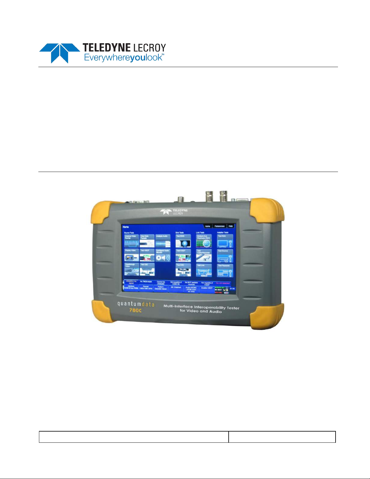
1.3 Introducing the 780C Multi-Interface Interoperability Tester
The 780C Multi-Interface Interoperability Tester is a portable multimedia pattern generator that enables you to
conduct quick, on-site verification testing of your HDMI, HDBaseT and 3G-SDI systems and analog video
displays. The 780C is equipped with both reference source and reference sink HDMI, HDBaseT and 3G-SDI
interfaces allowing you to test audio, video and protocols—HDCP, EDID, CEC & infoframes—of any type of
HDMI, HDBaseT and 3G-SDI device: sources, repeaters and sinks. Because the 780C has both digital video
outputs and inputs, you can test cables and systems with splitters, extenders and switches as well with the
optional pixel error test feature. You can also test hybrid digital video systems comprised of HDMI, HDBaseT
and 3G-SDI devices.
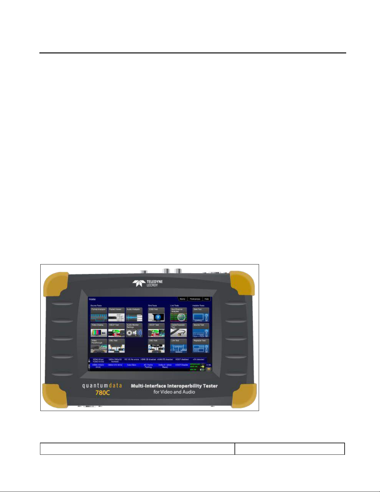
A color touch display makes the 780C easy and convenient to use. When testing a digital video source device
you can toggle between operating the unit through the touch screen and viewing the incoming video from the
source.
Page 7
780C Multi-Interface Interoperability Tester – User Guide Page 7
January 19, 2017
Revision A9
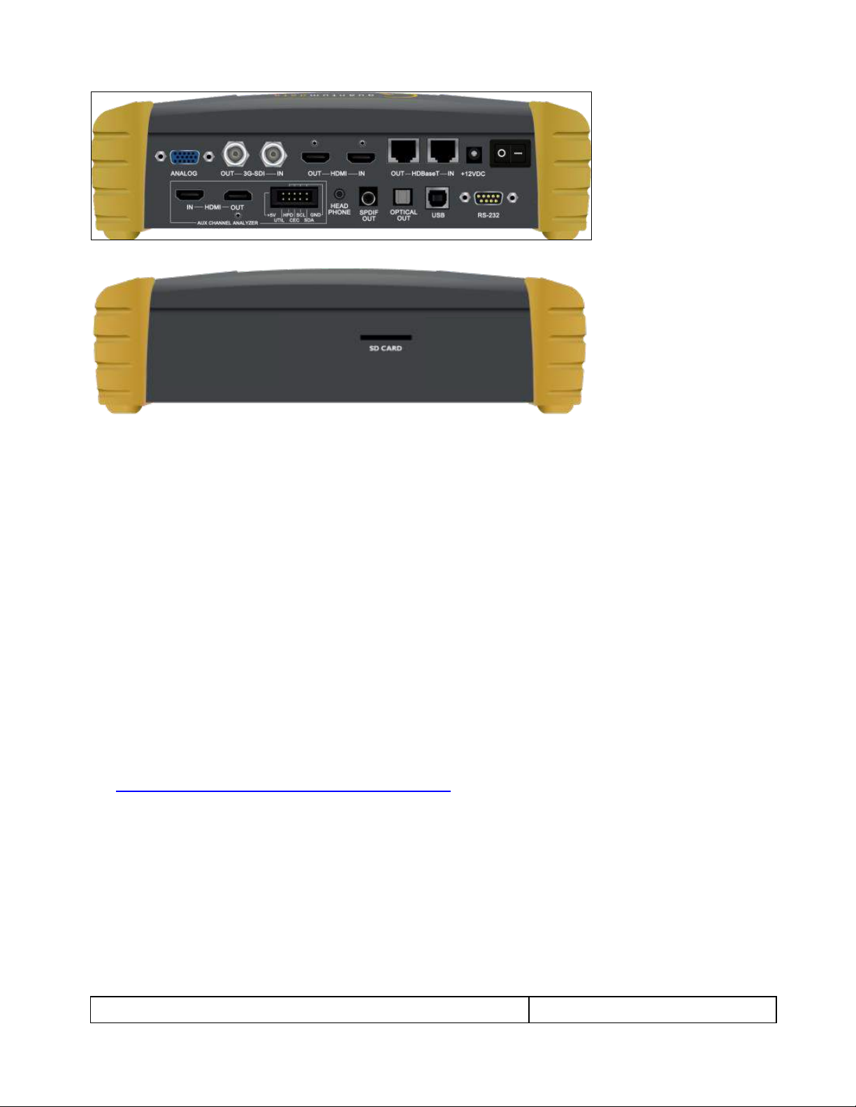
Note: 780C Image above shows the front edge with the SD Card slot which is used for storing and loading
bitmaps, reports and for recovery in the event of a failed upgrade.
1.4 Overview of 780C features
The 780C Multi-Interface Interoperability Tester provides a rich set of features. The following is a list of
available options and the key features and benefits of each:
1.4.1 Standard features
The following features are standard with the 780C:
Pattern testing for HDTVs - Enables you to conduct pattern testing for an HDTV through the digital video
and analog component outputs. Provides dozens of patterns with variation options on most.
Custom bitmaps and pattern scrolling – The 780C enables you to import bitmaps for use in pattern testing.
You can initiate a scroll of these bitmaps with user control over the rate and extent of horizontal movement.
Create custom formats using the standalone Format Editor.
3D bitmap pattern testing – The 780C enables you to import 3D bitmaps for use in pattern testing. You can
create your own bitmaps from any stereoscopic images you have using the Quantum Data Bitmap
Conversion Tool available from the Quantum Data website:
http://www.quantumdata.com/apps/3D/BMP_conv.asp. There are some sample 3D bitmaps on this
webpage as well.
Video confidence test of an HDMI, HDBaseT or 3G-SDI source device – The 780C enables you to view the
incoming video on the 780C’s LCD screen. 780C enables the incoming image to be routed out the digital
video output connector if unused. 780C also enables scrolling to view an entire unscaled 4K image
received on the HDMI and HDBaseT input ports.
Audio confidence test of an HDMI, HDBaseT or 3G-SDI source device – The 780C enables you to listen to
the incoming LPCM audio through the 780C’s headphone jack on the front edge or through an embedded
speaker. There will be no sound when compressed audio is received on the incoming HDMI stream.
Audio Return Channel confidence test of an HDMI 1.4 A/V receiver – The 780C can emulate an ARC Tx
device on its HDMI IN port. Note: The 780C does not support enabling ARC on the AV receiver, therefore
you will have to enable ARC through some other means.
Page 8

780C Multi-Interface Interoperability Tester – User Guide Page 8
January 19, 2017
Revision A9
Audio testing for AVRs and HDTVs – The 780C provides multi-channel digital audio test patterns through
the HDMI, HDBaseT., 3G-SDI, SPDIF and optical outputs. A variety of audio patterns and formats are
provided at sampling rates from 32kHz up to 192kHz and bit depths of 16, 20 and 24. Format supported
are Dolby Digital and DTS compressed formats and lossless compressed or high bit rate HDMI formats.
Installer Utility – Provides simplified diagnostics of HDMI and HDBaseT interoperability problems in an
installation. The Installer utility enables installers to connect the 780C into an HDMI/HDBaseT network and
quickly conduct diagnostics without required detailed knowledge of protocols.
Command line interface for automated testing.
1.4.2 Network Analyzer features
The following Network Analyzer features are available:
HDCP test of an HDMI or HDBaseT sink or input to a repeater device – The 780C enables you to run an
HDCP functional test on an HDMI or HDBaseT sink device directly or through a repeater device.
EDID test of an HDMI or HDBaseT HDTV, projector or input to a repeater device – The 780C enables you
to run an EDID functional test on an HDMI or HDBaseT sink device directly or through a repeater device.
You can view the entire EDID in human readable text. You can also run a portion of EDID compliance test.
Video test of an HDMI, HDBaseT or SDI source device – The 780C provides an HDMI, HDBaseT or SDI
input for testing HDMI, HDBaseT or SDI source devices. You can run a verification test of a video source
which includes timing and format information and an indication of whether the video is HDCP content
protected.
Data Island test of an HDMI or HDBaseT source device – The 780C provides an HDMI/HDBaseT input for
testing HDMI or HDBaseT source devices. You can view the infoframes and other data islands.
Audio test of an HDMI, HDBaseT or 3G-SDI source device – The 780C provides HDMI, HDBaseT and 3G-
SDI inputs for testing source devices. You can run a verification test of an audio source which includes
decoding of the audio IEC headers, audio infoframes and audio sample packet headers (for HDMI and
HDBaseT and parsing out of the channel status bits for 3G-SDI as well.
EDID test of HDMI or HDBaseT source device or outputs – The 780C’s HDMI or HDBaseT input ports can
be provisioned with any EDID you have access to. You can verify that a source device responds properly to
the provisioned EDID. The EDID could be a known-good EDID or an EDID that you have created
specifically for testing.
HDCP test of an HDMI or HDBaseT source device – The 780C enables you to run a test to determine how
many HDCP devices an HDMI or HDBaseT source can support during HDCP authentication.
CEC ping test of any HDMI device – The 780C enables you to run a CEC ping test on an HDMI device.
1.4.3 Cable and Repeater test features
The following features are available with the Cable and Repeater test option:
Cable & Repeater test – Because the 780C has both digital video inputs and outputs, you can loop a cable
or entire distribution networks comprised of splitters, extenders, repeaters, switches, even hybrid networks
with HDMI, HDBaseT or 3G-SDI components, from the 780C’s output to input and run a pseudo-random
noise pattern test to determine pixel errors on the TMDS lines. The feature also runs a continuity test on
the HDMI or HDBaseT DDC test pair, CEC bus, the +5V line and the hot plug lead. The Repeater test also
shows you the hot plug delay between the downstream side and the upstream side and the pulse width.
The Cable & Repeater Test enable you to test a cable, repeater or distribution network if the source and
sink ends are collocated. If the source and sink ends are not collocated then you need to use the Frame
Compare test described below.
1.4.1 Report File Creation feature
The following features are available with the Report File Creation option:
Page 9

780C Multi-Interface Interoperability Tester – User Guide Page 9
January 19, 2017
Revision A9
Table 1-1: 780C Shipping Box Contents
Item Description
Part No.
780C Multi-Interface Interoperability Tester.
00-00236
12V DC, 3.3A (40 W) output - Power Supply / Adapter.
25-00106
Line cord for 12V Power Supply.
30A00400A03
Cable: HDMI-to-HDMI Type A.
30-00146
Cable: VGA to (3) RCA adaptor.
30-00203
Cable: USB.
30-00163
Enables residential installers, proAV integrators and test engineers in R&D to produce a record of the tests
they perform. Reports can be run on HDCP, Format Analyzer, Audio Analyzer, Cable tests, auxiliary
channel analyzer tests for any interface (HDMI, HDBaseT or DisplayPort). The reports can be provided to
customers, colleagues or to the contracting agent to verify and demonstrate project completion. The reports
can be run on a single test or aggregated for a series of tests. The reports can be transferred by SD card or
the USB interface and viewed in a standard browser or any text editor.
1.4.2 Auto EDID Test
The following features are available with the Auto EDID test option:
Select a series of EDIDs to test a source’s handling of them.
Emulate the EDIDs on the 780C HDMI or HDBaseT Input port.
Test runs automatically and flags improper handling. Checks for proper VIC, timing, video type, color depth
and sampling mode.
1.4.3 Auxiliary Channel Analyzer for DDC monitoring features
The following features are available with the Auxiliary Channel Analyzer test options:
DDC monitoring with Auxiliary Channel Analyzer (ACA) – The 780C ACA enables you to monitor HDMI or
HDBaseT CEC DDC transactions such as HDCP and EDID as well as hot plug related events while
emulating an HDMI or HDBaseT source and/or an HDMI or HDBaseT sink device(s) in a system. You can
also monitor passively between two HDMI/HDBaseT devices. When monitoring passively you can also
view the +5V status.
1.4.4 What is in the 780C shipping box
The 780C instrument shipping container includes the items listed in Table 1-1 below:
Page 10

780C Multi-Interface Interoperability Tester – User Guide Page 10
January 19, 2017
Revision A9
Table 2-1: 780C Video Interfaces
Video Interface
Description
HDMI (1) Output Type A
Single HDMI output connector. Supports HDMI 1.4x:
Bit Depth: 24/30/36 bit.
Colorimetry: RGB, YCbCr.
Sampling: 4:4:4, 4:2:2, 4:2:0.
Pixel rate: Timings up to 300MHz for 4K x 2K resolutions.
DVI support through HDMI to DVI adapter cable (RGB, 4:4:4, 24 bit).
Audio: LPCM, Dolby Digital and DTS (more details below).
HDBaseT (1) Output RJ-45
Single HDBaseT output connector. Supports HDBaseT 1.x:
Bit Depth: 24/30/36 bit.
Colorimetry: RGB, YCbCr.
Sampling: 4:4:4, 4:2:2, 4:2:0.
Pixel rate: Timings up to 300MHz for 4K x 2K resolutions.
DVI support through HDMI to DVI adapter cable (RGB, 4:4:4, 24 bit).
Audio: LPCM, Dolby Digital and DTS (more details below).
3G-SDI (1) Output BNC
3G-SDI output connector.
Bit Depth: 24/30/36 bit.
Colorimetry: YCbCr.
Sampling: 4:4:2.
Data rate: Timings up to 2.97Gbps.
Audio: LPCM, Dolby Digital and DTS.
Analog Output – Component and VGA (HD15F)
Bit Depth: 24 bit color depth.
Colorimetry: RGB, YPbPr.
Pixel rate: 80MHz.
Sync types: separate and composite.
HDMI (1) Input Type A
Single link HDMI input connector. Supports HDMI 1.4x:
Colorimetry: RGB, YCbCr.
Sampling: 4:4:4, 4:2:2, 4:2:0.
Pixel rate: Timings up to 300MHz for 4K x 2K resolutions.
HDBaseT (1) Input RJ-45
Single link HDBaseT input connector. Supports HDBaseT 1.x:
Colorimetry: RGB, YCbCr.
Sampling: 4:4:4, 4:2:2, 4:2:0.
Pixel rate: Timings up to 300MHz for 4K x 2K resolutions.
3G-SDI (1) Input BNC 5
Single link HDMI input connector.
Colorimetry: YCbCr.
Sampling: 4:2:2.
Data rate: Timings up to 2.97Gbps.
2 Physical Interfaces of the 780C Multi-Interface Interoperability Tester
This section describes the administration, video and audio interfaces on the 780C test instrument:
2.1 Video Interfaces
Table 2-1 below describes the video interfaces on the 780C test instrument, these interfaces are used to render
test patterns for testing consumer electronic HDTVs and computer displays.
Page 11

780C Multi-Interface Interoperability Tester – User Guide Page 11
January 19, 2017
Revision A9
Table 2-2: 780C Audio Interfaces
Interface
Description
HDMI (1) Output Type A
Single HDMI output connector. Supports HDMI 1.4x:
Channels: 8.
Bits per sample: 16, 20, 24.
Sampling rates (kHz): 32.0, 44.1, 48.0, 88.2, 96.0, 176.4, 192.0.
Formats: LPCM, Dolby Digital (clips), DTS (clips)
HDBaseT (1) RJ-45
Single HDBaseT output connector. Supports HDBaseT 1.x:
Channels: 8.
Bits per sample: 16, 20, 24.
Sampling rates (kHz): 32.0, 44.1, 48.0, 88.2, 96.0, 176.4, 192.0.
Formats: LPCM, Dolby Digital (clips), DTS (clips)
SPDIF - RCA
SPDIF RCA audio connector:
Channels: 8 (clips)
Bits per sample: 16, 20, 24.
Sampling rates (kHz): 32.0, 44.1, 48.0, 96.0
Formats: LPCM, Dolby Digital (clips), DTS (clips)
Optical – JIS FOS
Optical audio connector:
Channels: 8 (clips)
Bits per sample: 16, 20, 24.
Sampling rates (kHz): 32.0, 44.1, 48.0
Formats: LPCM, Dolby Digital (clips), DTS (clips)
HDMI (1) Input (Audio Return Channel) Type A
HDMI ARC SPDIF:
Channels: 8 (clips)
Bits per sample: 16, 20, 24.
Sampling rates (kHz): 32.0, 44.1, 48.0, 96.0
Formats: LPCM, Dolby Digital (clips), DTS (clips)
2.2 Audio interfaces
Table 2-2 below describes the audio interfaces supported on the 780C test instrument.
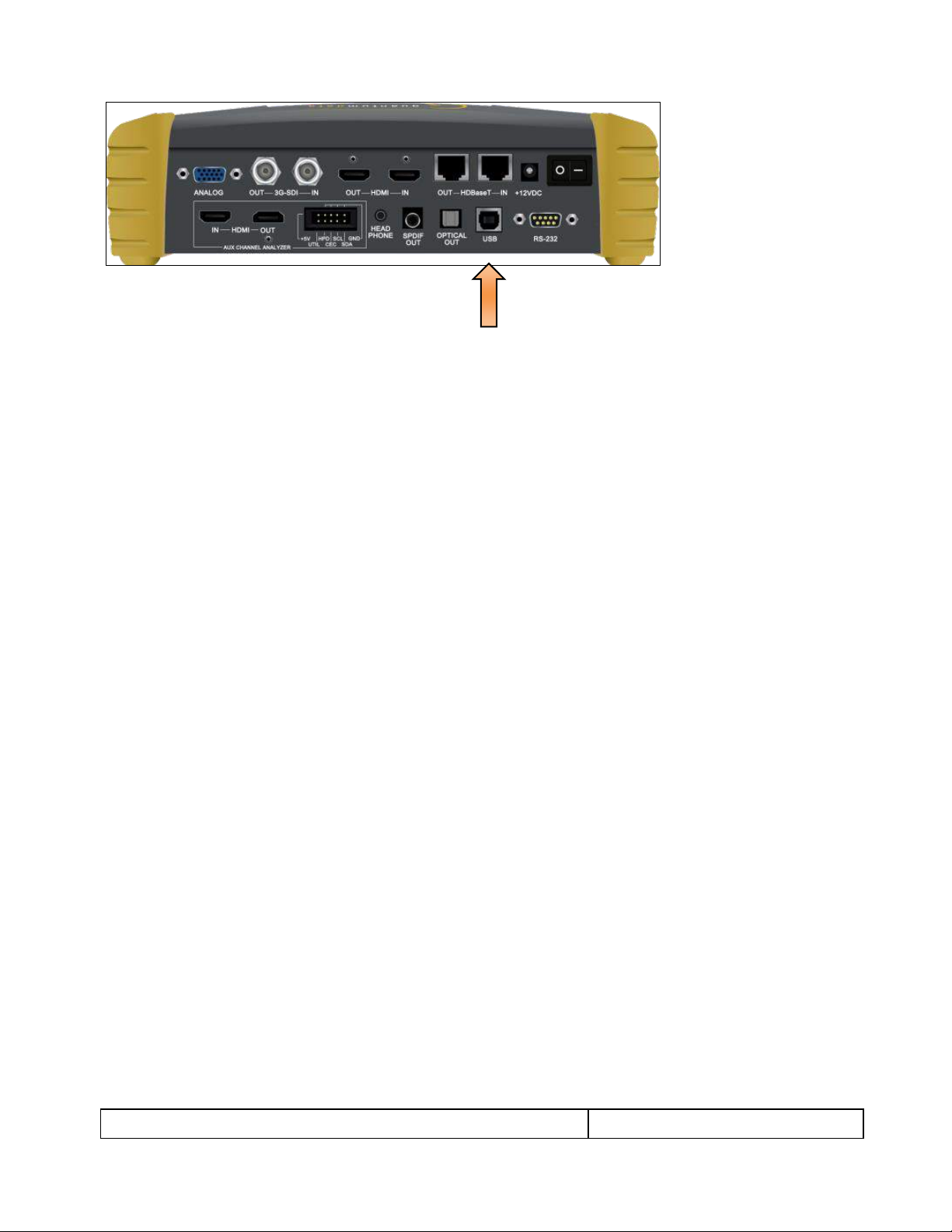
2.3 Administrative Interface
The 780C is equipped with a USB interface. This interface is used to download custom bitmaps and to upgrade
firmware and issue commands. The USB interface is a peripheral device. There are two modes:
COM - Command Mode. Used for sending commands to set the interface, select formats and patterns.
Disk - Mass Storage Mode. Used for downloading bitmaps, audio clips and upgrading firmware or
gateware.
Page 12
780C Multi-Interface Interoperability Tester – User Guide Page 12
January 19, 2017
Revision A9
Page 13
780C Multi-Interface Interoperability Tester – User Guide Page 13
January 19, 2017
Revision A9
3 General Operation
This section describes power up, power usage and general operation.
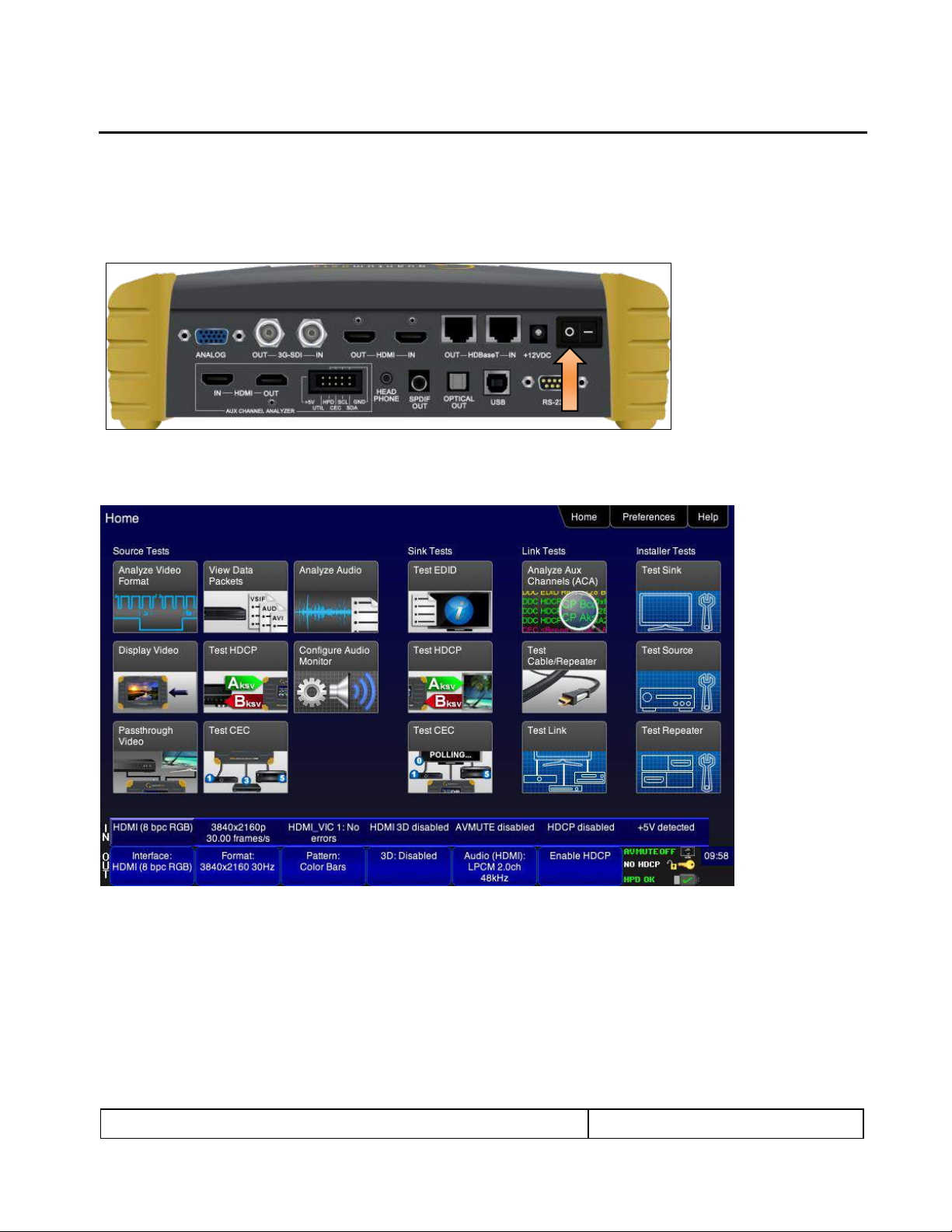
3.1 Power Considerations
The 780C has a rocker style power switch on the back panel. Refer to the photo below.
The 780C is supplied with the Part No 25-00106 12V DC power supply adapter as well as a part number
30A00400A03 line cord.
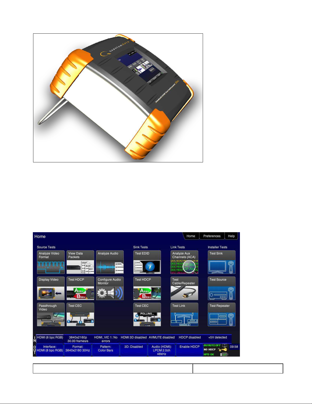
3.2 Tilt Bail
The 780C has support bail for convenience in viewing. This is depicted in the illustration below. (The illustration
shows the 780; however, the 780C tilt bail operates in the same manner.)
Page 14
780C Multi-Interface Interoperability Tester – User Guide Page 14
January 19, 2017
Revision A9
3.3 Navigating through the 780C User Interface
The 780C user interface is a color touch screen display 800 by 480. A single touch will activate an item on the
screen or take you down to a lower level menu. A + indicates that you have to double touch to navigate down to
a lower level menu.
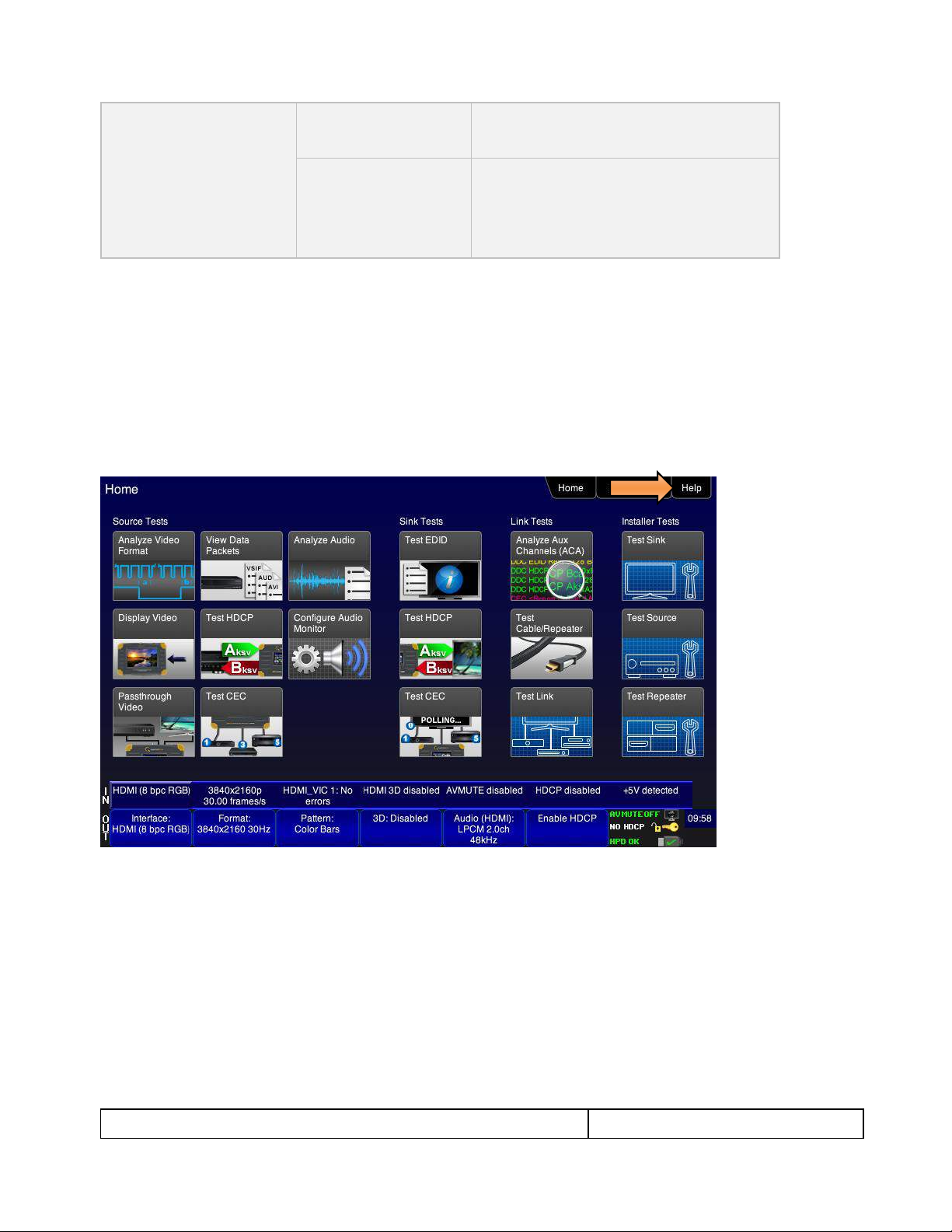
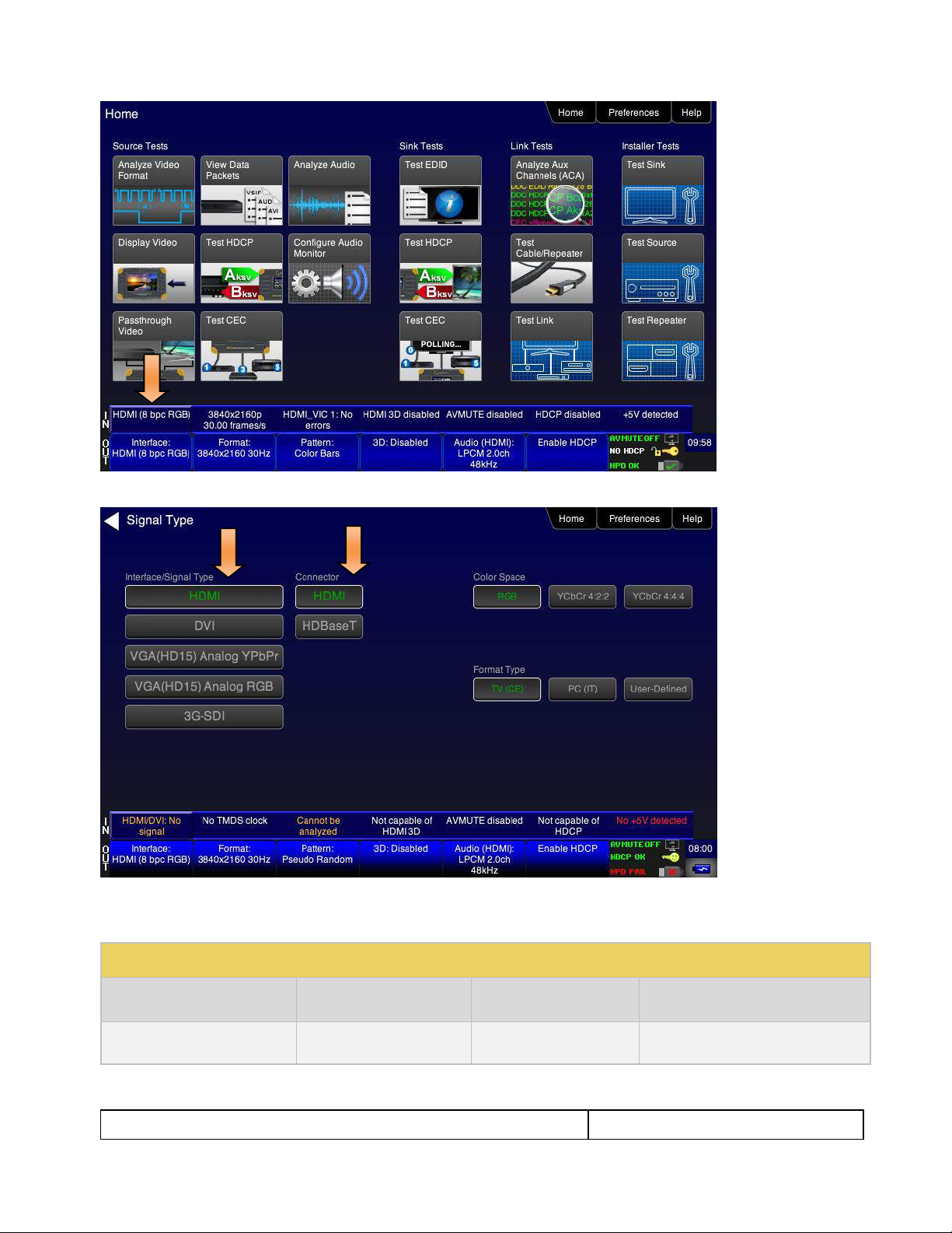
3.3.1 Home Menu items
The 780C’s Home screen is shown below.
Page 15

January 19, 2017
Revision A9
Table 3-1: Top Level Menu
Item
Submenu - Pattern
Third Level Menu
Value
Top Menu Bar
Home / Back
navigation
See Below
Enables you to navigate back to the previous
screen.
Reports Menu
Note: Changes to
Add a Report when
a test is run.
Report File Format
Text Only
HTML
Enables you to specify the format of a report.
Start Report
Initiates a report
Add Comment
Grayed out until Start Report is activated
Set Save Dir
Enables you to create and name a directory on the
SD card or the 780 file system.
Save to SD
Enables you to create and name a report on the SD
card to save a report to. Unavailable without an SD
card in the slot.
Save to Unit
Enables you to create and name a report in the 780
file system to save a report to.
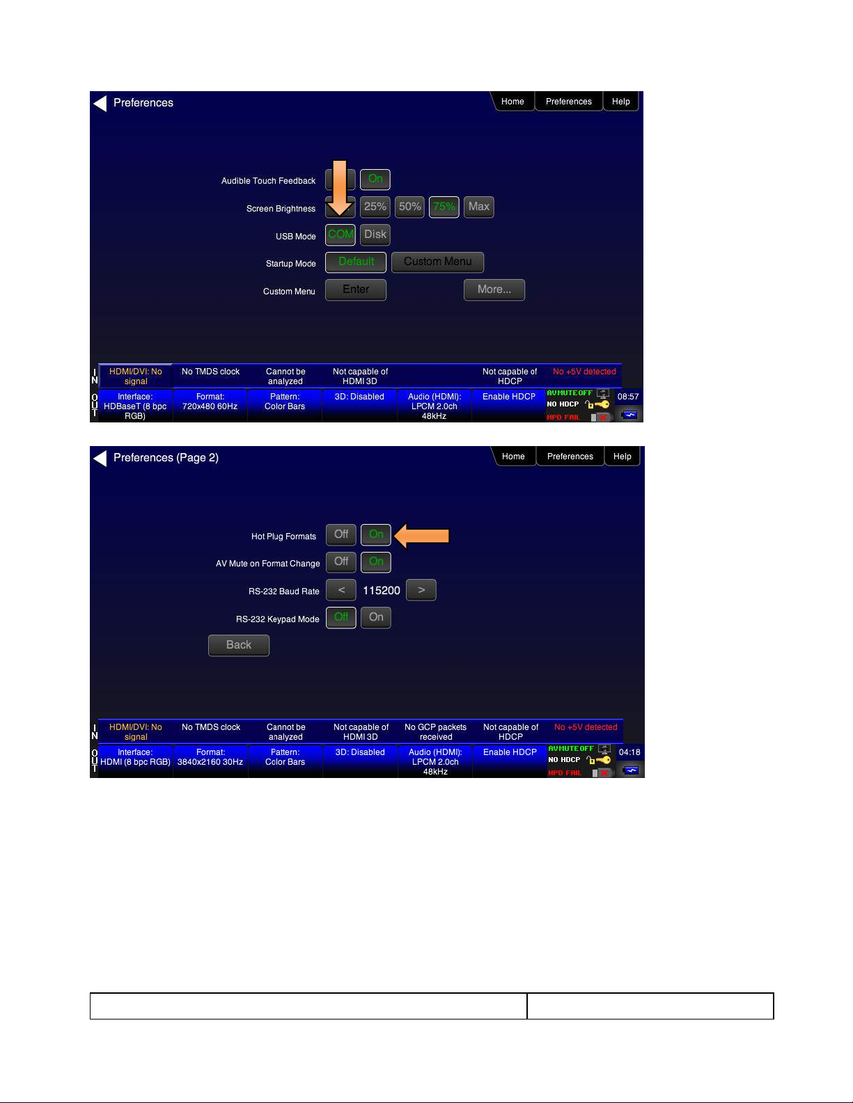
Preferences
Page 1
Audible Touch
Off
On
Screen Brightness
Min
25%
50%
75%
Max
USB Mode
COM for commands
Disk for downloading files and upgrades
Startup Mode
Set the 780’s menu configuration to the default
menu (shown throughout this User Guide).
Custom Menu – Utilize a configuration that you
have created.
Custom Menu
Enter to navigate to custom menu screen.
Preferences
Page 2
Hot Plug Formats
On – 780C automatically select the formats in
the EDID of the connected HDTV.
Off – 780C will not automatically select the
formats in the EDID of the connected HDTV.
AVMute on Format
Change
On – AVMute will occur when the resolution is
changed on the 780C HDMI output.
Off – AVMute will occur when the resolution is
changed on the 780C HDMI output.
RS-232 Baud Rate
Configure the baud rate of the RS-232 interface
on the 780C (N/A to 780).
RS-232 Keypad Mode
Off – Keypad connected to RS-232 is disabled.
On – Keypad connected to RS-232 is enabled.
Help
Upgrades
USB Storage Flash
Application Flash
FPGA Flash
Touchscreen
Calibrate the touch screen display
Source Tests Buttons
Analyze Video
Format
Viewing Source Data Island Packet
780C Multi-Interface Interoperability Tester – User Guide Page 15
Table 3-1 below shows functions available from the Home screen.
Page 16
780C Multi-Interface Interoperability Tester – User Guide Page 16
January 19, 2017
Revision A9
Display Video
Testing Video from an HDMI Source Device
Passthrough Video
Viewing the Incoming 4K Video on a Connected Display using Passthrough
View Data Packets
Viewing Source Data Island Packet
Test HDCP
Testing HDCP Max Devices on an HDMI Source Device
Test CEC
Viewing the CEC devices on an HDMI network
Analyze Audio
Testing Audio of an HDMI Source Device
Configure Audio
Monitor
Procedures for Monitoring LPCM Audio from a Source Device (780C only)
Sink Tests Buttons
Test EDID
Verifying the EDID on an HDMI HDTV or HDMI Repeater Device
Test HDCP
Testing HDCP on an HDMI HDTV or HDMI Repeater Device
Test CEC
Viewing the CEC devices on an HDMI network
Link Tests Buttons
Analyze Aux Channel
Procedures for Monitoring Auxiliary Channel events and transactions
Test Cable/Repeater
Using the 780C Test Instrument to Test HDMI Cable or Repeaters
Test Link
Procedures for Installer Utility
Installer Tests Buttons
Test Sink
Using the 780C Test Instrument Installer Utility
Test Source
Using the 780C Test Instrument Installer Utility
Test Repeater
Using the 780C Test Instrument Installer Utility
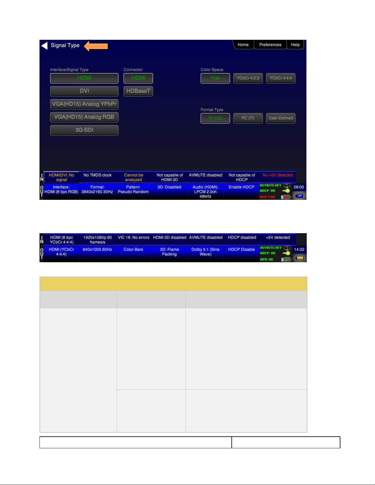
3.3.2 Back Navigation
When you navigate away from the Home screen a white arrow will appear in the upper left next to the name of
the of the screen you are on. You can navigate to the previous screen by touch selecting this arrow. In the
example below, touch selecting the upper left area on or near the white, left facing arrow next to Signal Type
will take you to the previous screen.
Page 17
780C Multi-Interface Interoperability Tester – User Guide Page 17
January 19, 2017
Revision A9
Table 3-2: Status Bar
Type
Status Item
Function
HDMI/HDBaseT/SDI IN
Video Type Status
Indicates the status of video on the
HDMI/HDBaseT/SDI Rx ports. This includes:
Video interface: HDMI or DVI, HDBaseT or
SDI
Color depth: 8, 10, 12
Video type: RGB or YCbCr
Sampling mode: 4:4:4, 4:2:2, 4:2:0
Note: When SDI is active on the input, the Video
Type is always YCbCr and the sampling is always
4:2:2.
Video Resolution Status
Indicates the video resolution on the HDMI Rx port.
This includes:
Horizontal Active in pixels
Vertical Active in pixels
Frame rate
3.3.3 Status Bar
The 780C has a status bar on the bottom of the screen.
The items in the status bar are described in the Table 3-2.
Page 18

780C Multi-Interface Interoperability Tester – User Guide Page 18
January 19, 2017
Revision A9
Video Identification Status
Indicates the video resolution on the HDMI Rx port.
This includes:
Horizontal Active in pixels
Vertical Active in pixels
Frame rate
3D Status
Indicates the status of 3D video for HDMI or
HDBaseT. This includes:
3D enabled or disabled
3D format
AVMute status
Indicates the AVmute status, enabled or
disabled. Applies only to HDMI and HDBaseT.
HDCP Status
Indicates whether the incoming video is encrypted
with HDCP.
+5V Status
Indicates whether +5V is detected from the HDMI
or HDBaseT source.
HDMI/HDBaseT/SDI OUT
Video Type
Status/Selection
Indicates the video on the HDMI/HDBaseT/SDI Tx
ports. This includes:
Video interface: HDMI or DVI
Color depth: 8, 10, 12
Video type: RGB or YCbCr
Sampling mode: 4:4:4, 4:2:2, 4:2:0
Note: When SDI is active on the output, the Video
Type is always YCbCr and the sampling is always
4:2:2.
Provides access to the Video Signal Type screen.
Video Resolution
Status/Selection
Indicates the video resolution on the HDMI Tx port.
This includes:
Horizontal Active in pixels
Vertical Active in pixels
Frame rate
Provides access to the Video Format screen.
Video Pattern
Status/Selection
Indicates the video pattern on the HDMI Tx port.
Provides access to the Video Pattern screen.
3D Format
Status/Configuration
Indicates the status of 3D video. This includes:
3D enabled or disabled
3D format
Provides access to the 3D video configuration
screen.
Audio Status
Indicates the Audio status:
Audio format
Audio channels
Audio sampling rate
Page 19
780C Multi-Interface Interoperability Tester – User Guide Page 19
January 19, 2017
Revision A9
HDCP Status
Indicates whether the incoming video on the HDMI
In port is encrypted with HDCP.
AVMute
HDCP Status
+5V Status
Indicates the status of the following for HDMI or
HDBaseT:
AVMute active/inactive status
HDCP active/inactive status
+5V present/not present status
3.4 Calibrating the LCD
You can calibrate the touch screen of your 780 if necessary.
Important Note: Please follow the procedures below carefully. Improper calibration can lock the unit up. It is
preferable that you contact Quantum Data Support unless you have learned how calibrated the screen
properly.
Use the following procedures to perform the calibration.
1. From the Home menu, navigate to the Help menu by pressing the Help activation button on the upper
status bar. The Home menu is shown below.
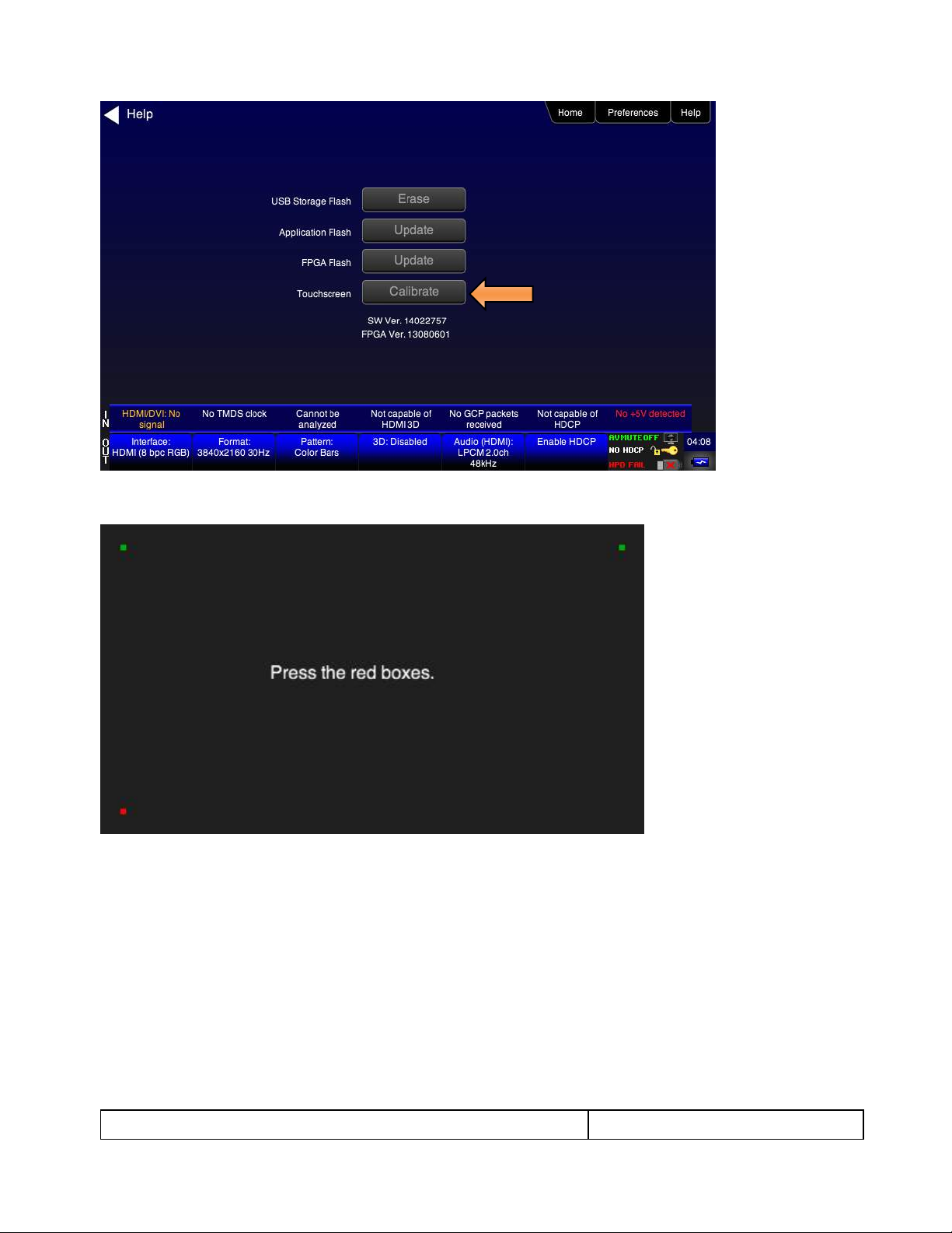
The Help menu appears as shown below:
Page 20
780C Multi-Interface Interoperability Tester – User Guide Page 20
January 19, 2017
Revision A9
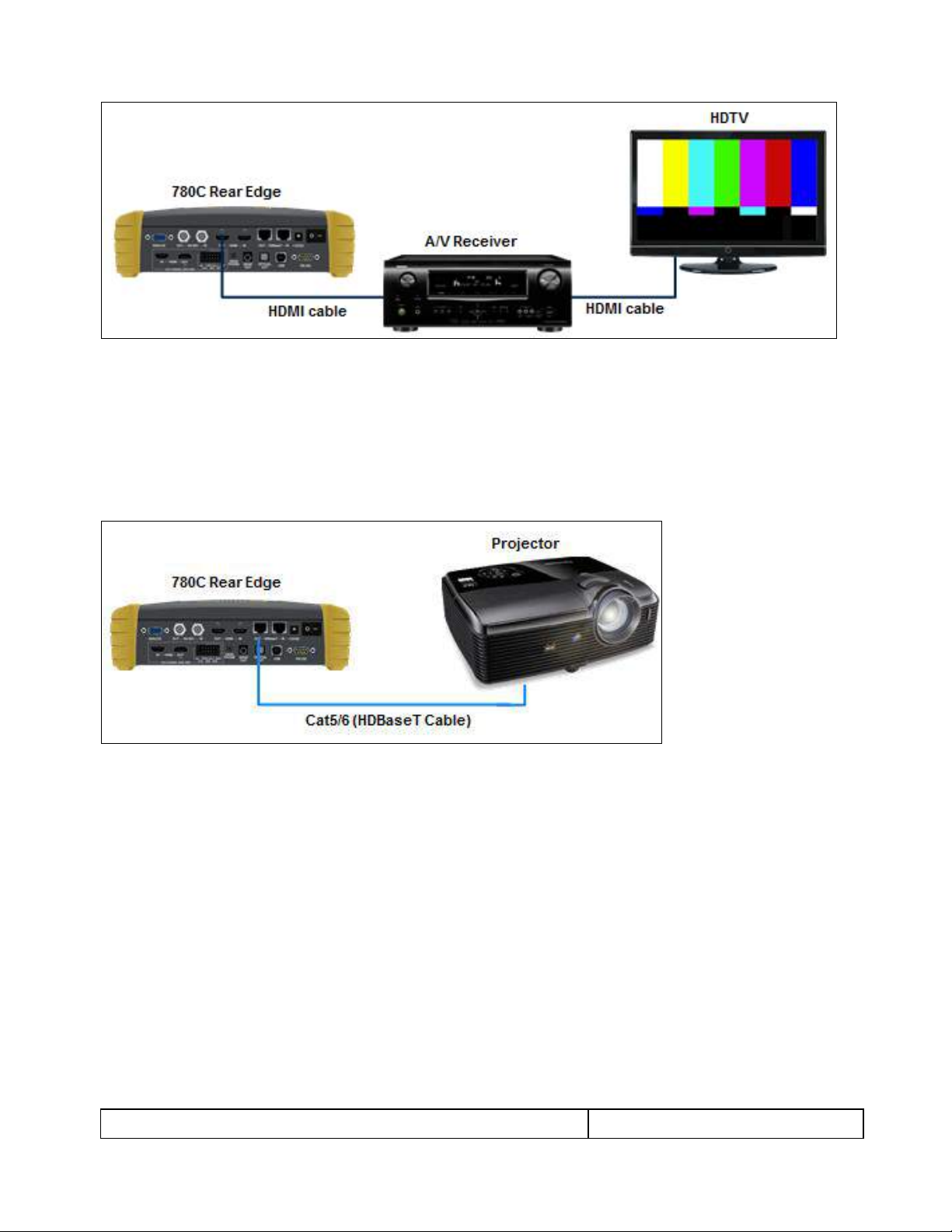
2. Touch select the Calibrate activation button. A screen appears instructing you to press each of four red
squares.
When you finish touch selecting the fourth box, the calibration is completed and you will return to the Home
menu.
3. If the calibration fails and you cannot access the menus, establish a command line session and enter the
calibration command:
TCAL
This will cause the screen to display the calibration screen again.
Page 21

780C Multi-Interface Interoperability Tester – User Guide Page 21
January 19, 2017
Revision A9
4 Using the 780C Test Instrument to Video and Audio Pattern Tests on
Sink Devices
This chapter provides procedures for running audio and video pattern tests on high definition sink devices such
as HDTVs and projectors. The features and functions described in this chapter are provided with the standard
780C; no options are required. The following signal types are supported.
HDMI (via the HDMI physical connector)
DVI (via the HDMI physical connector)
HDBaseT (via the HDBaseT physical connector)
3G-SDI (via the SDI physical connector)
YPbPr Component analog (via the HD VGA connector)
RGB Analog (via the HD VGA connector).
4.1 Making Physical Connections - HDMI
The first step in testing a sink device is to make the HDMI physical connections between the 780C and the
device(s) under test.
4.1.1 Connecting the 780C to the Display Device - HDMI
Use the following procedures to make the physical connections from the 780C to the display device under test.
1. Make the cable connection between the appropriate the 780C video output connector (e.g. HDMI OUT or
ANALOG) connector and the input connector of the HDTV using the cables supplied.
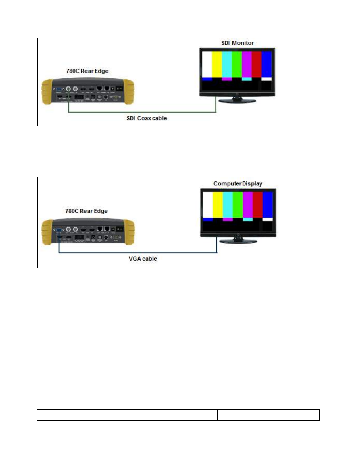
2. Alternatively you may connect from the 780C video output connector to an HDTV through an HDMI
repeater device such as an A/V receiver. In this case make the HDMI connection between the HDMI OUT
connector on the 780C and the HDMI input of the HDMI repeater device using an HDMI-to-HDMI cable.
Then connect the HDTV to an active output on the repeater. The following illustrations depict the typical
test configurations.
Page 22
780C Multi-Interface Interoperability Tester – User Guide Page 22
January 19, 2017
Revision A9
4.1.2 Connecting the 780C to the Display Device - HDBaseT
Use the following procedures to make the physical connections from the 780C to the display device under test.
1. Make the cable connection between the appropriate the 780C video HDBaseT output connector and the
input connector of the HDBaseT device.
The following illustrations depict the typical test configurations.
4.1.3 Connecting the 780C to the Display Device - SDI
Use the following procedures to make the physical connections from the 780C to the display device under test.
1. Make the cable connection between the appropriate the 780C video SDI output connector and the input
connector of the display or monitor using the cables supplied.
Page 23
780C Multi-Interface Interoperability Tester – User Guide Page 23
January 19, 2017
Revision A9
4.1.4 Connecting the 780C to the Display Device - Analog
Use the following procedures to make the physical connections from the 780C to the display device under test.
1. Make the cable connection between the appropriate the 780C video VGA output connector and the input
connector of the HDTV or computer monitor using the cables supplied.
4.2 Selecting a Signal Type and Resolution
After making the physical connections between the 780C and the display device under test you will need to
select the signal type, Resolution and Frame Rate for the sink device under test.
4.2.1 Procedures for Selecting a Signal Type
The procedures below describe how to select the active signal type.
1. Power up the 780C using the rocker switch on the back panel.
2. Touch select the Signal Type activation button on the OUT Status Bar (see screen example below).
Page 24
780C Multi-Interface Interoperability Tester – User Guide Page 24
January 19, 2017
Revision A9
Table 4-1: Signal Type
Signal Type Name
Physical Connector
Option
Option Values
HDMI
HDMI OUT via HDMI to
Color Space
YCbCr 4:4:4, 4:2:2, 4:2:0
RGB
The Signal Type menu appears as shown below.
3. Touch select the desired signal type using the associated activation button, example HDMI.
4. Touch select the options for the Signal Type. Use the information in Table 4-1 below as a guide:
Page 25

780C Multi-Interface Interoperability Tester – User Guide Page 25
January 19, 2017
Revision A9
HDMI cable (provided)
Bit Depth
8
10
12
Format Type
TV – Uses limited color range
PC – Uses full color range
User
DVI
HDMI OUT via HDMI to DVI
cable (not provided)
Format Type
TV – Uses limited color range
PC – Uses full color range
User
HDBaseT
HDBaseT OUT via
HDBaseT to HDBaseT
cable (not provided)
Color Space
YCbCr 4:4:4 4:2:2, 4:2:0
RGB
Bit Depth
8
10
12
Format Type
TV – Uses limited color range
PC – Uses full color range
User
3G-SDI
SDI OUT via SDI to SDI
cable (not provided)
Color Space
YCbCr 4:2:2
Bit Depth
8
Format Type
TV – Uses limited color rang
YPbPr Analog
ANALOG HD-15 (VGA) via
HD to 3-RCA cable
(provided)
Sync Type
Sep[arate] Sync
Sync on Green
RGB Analog
ANALOG HD-15 (VGA) via
VGA cable (not provided)
Format Type
TV – Uses limited color range
PC – Uses full color range
User
Sync Type
Sep[arate] Sync
Sync on Green
4.2.2 Procedures for Selecting an Resolution and Frame Rate – HDMI and HDBaseT
The procedures below describe how to select the resolution for HDMI and HDBaseT outputs.
Note: You can create your own custom formats using the Quantum Data Format Editor. These procedures are
described in Creating and Using Custom Formats, EDIDs and Bitmaps.
When you make a physical connection to an HDTV or monitor, a hot plug event will occur. There are two
modes the 780C can be set in when testing HDMI or HDBaseT sink devices that determine how the 780C
responds to this hot plug event: 1) Hot plug formats On; 2) Hot plug formats Off.
When hot plug formats are On and a hot plug event occurs, the 780C will read the EDID of the display device
connected to its output port. It will then automatically configure the list available signal types (resolutions and
frame rates) to only those supported by the HDMI or HDBaseT sink device. The 780C will also be configured to
output the signal indicated in the EDID as the “preferred” timing. The preferred timing is highlighted in green
following a hot plug event.
When hot plug formats are Off, the 780C will display all viable HDMI or HDBaseT formats for the interface
whether they are supported by the display or not.
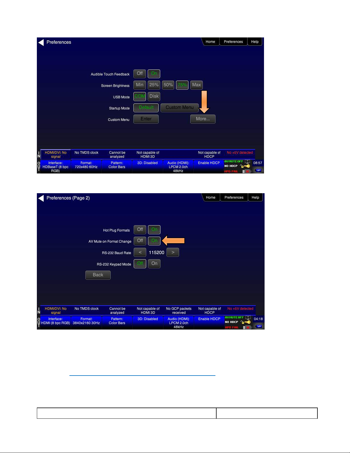
1. Select the Preferences from the 780C top level menu. Navigate to the second page by touch selecting the
More… key.
Page 26
780C Multi-Interface Interoperability Tester – User Guide Page 26
January 19, 2017
Revision A9
2. Select the Hot Plug Formats mode to On or Off as desired. Refer to the screen above.
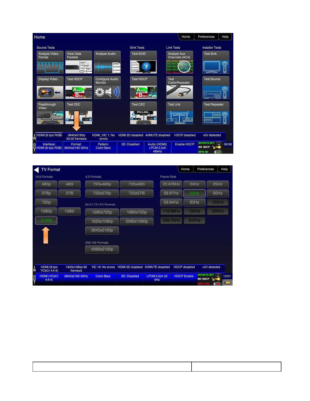
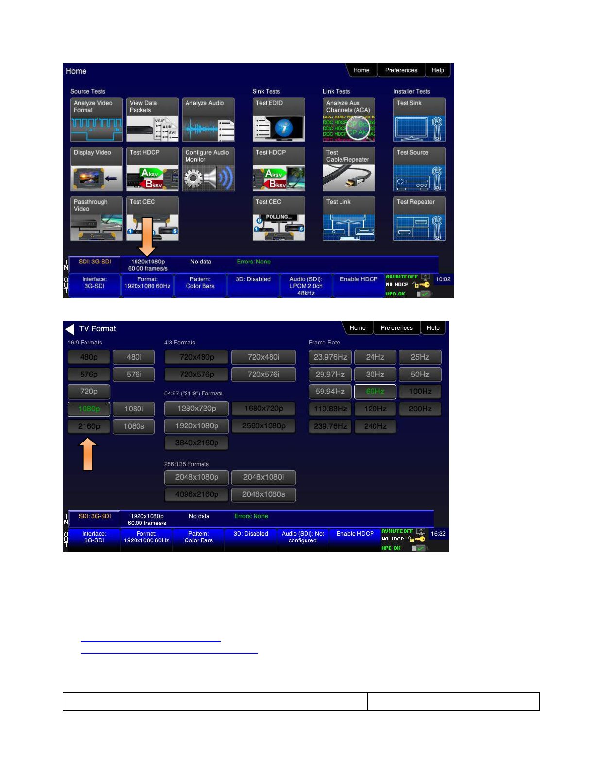
3. Touch select the Formats activation button on the Status bar OUT to access the Formats menu. Refer to
the figure below.
Page 27
780C Multi-Interface Interoperability Tester – User Guide Page 27
January 19, 2017
Revision A9
The Formats menu appears as shown below (example HDMI):
4. Touch select the desired format and Frame Rate (example 2160p at 30Hz above).
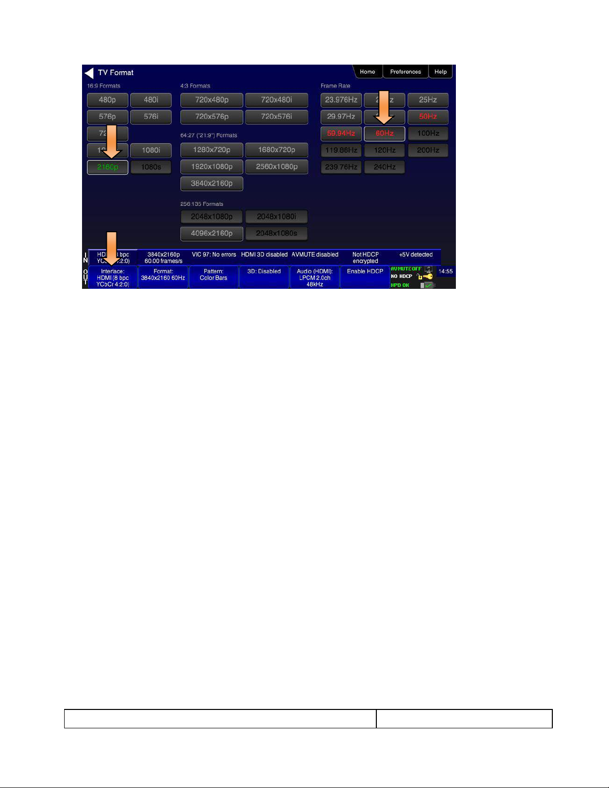
Note: The 780C supports 4K formats at 60Hz but only in 4:2:0 sampling mode. When a 4K format is
selected and the frame rate is set at 60Hz the 780C will automatically configure itself to 4:2:0
sampling. Refer to the example below:
Page 28
780C Multi-Interface Interoperability Tester – User Guide Page 28
January 19, 2017
Revision A9
For the HDMI formats, there are color codes that are applied to the Resolution and Frame Rate selections. The
following is a summary of their meaning:
A Resolution or Frame Rate with white lettering but with no outline – a Resolution or Frame Rate that
appears in the EDID and has a short video descriptor associated with it.
A Frame Rate with green lettering and with white outline – The Frame Rate that is currently selected.
A Frame Rate with red lettering but with no outline – The Frame Rate is not supported by the EDID for
that Resolution.
A Frame Rate(s) with green lettering and with white outline – The Frame Rate along with the currently
selected Resolution that is the “preferred” timing.
A Frame Rate with black lettering but with no outline – The Frame Rate is not supported by the standard
for the selected resolution.
Note: When you make a physical connection to an HDMI or HDBaseT HDTV or sink device, a hot plug
event will occur. If Hot Plug Formats is enabled on the Preference menu, when the hot plug event occurs,
the 780C will read the EDID of the display device connected to its output port. The output is automatically
set to the preferred timing which is highlighted in green following a hot plug.
4.2.3 Procedures for Enabling AVMute
The procedures below describe how to enable AVMute on the HDMI or HDBaseT output ports. AVMute is an
optional feature in HDMI or HDBaseT that enables a source to signal a sink to extinguish its audio and video.
The source, in this case the 780C emulating a source sets the AVMute Set flag in the general control packet.
The purpose of AVMute is to avoid audio artifacts when switching resolutions.
1. Select the Preferences from the 780C top level menu. Navigate to the second page by touch selecting the
More… key.
Page 29
780C Multi-Interface Interoperability Tester – User Guide Page 29
January 19, 2017
Revision A9
2. Touch select the On activation button next to AVMute on the screen below.
4.2.4 Procedures for Selecting a Resolution and Frame Rate – SDI
The procedures below describe how to select the resolution for the SDI output.
Note: You can create your own custom formats using the Quantum Data Format Editor. These procedures are
described in Creating and Using Custom Formats, EDIDs and Bitmaps.
1. Touch select the Formats activation button on the Status bar OUT to access the Formats menu. Refer to
the figure below.
Page 30
780C Multi-Interface Interoperability Tester – User Guide Page 30
January 19, 2017
Revision A9
The Formats menu appears as shown below:
2. Touch select the desired format and Frame Rate (example 2160p at 30Hz above).
4.3 Rendering Test Patterns on an HDTV
This subsection describes how to render test patterns on an HDTV. You will first have to complete the previous
procedures:
Making the physical connections
Selecting the Signal Type and Resolution
4.3.1 Procedures for Outputting Test Patterns
Page 31

780C Multi-Interface Interoperability Tester – User Guide Page 31
January 19, 2017
Revision A9
The procedures below cover cases where there is a direct connection between the 780C and the HDTV and
also where the 780C is connected to an HDTV through a repeater device.
1. From the Home screen on the 780C display, touch select the Video Pattern status and activation button
on the Status Bar as shown below.
2. Touch select the desired test pattern from the menu shown below. You can select patterns that are
standard with the 780C or bitmaps that you have imported.
Note: A “+” on the lower right portion of the pattern indicates that there are options related to the specific
pattern. In these cases you double touch select to access the lower level menu.
3. (If applicable) Specify the test pattern options. Use the information in Table 4-3 below as a guide.
Note: There may be additional patterns not shown in the table.
Page 32

780C Multi-Interface Interoperability Tester – User Guide Page 32
January 19, 2017
Revision A9
Table 4-3: Test Patterns
Pattern Name
Variant
Options
Range of Values
ColorBar patterns
Applications:
SMPTEBars - To adjust color
and hue.
Colorbars - To test a display’s
ability to product fully saturated
primary and secondary color.
SMPTE
Orientation - Vertical
Direction:
Left to Right
Right to Left
Orientation - Horizontal
Direction:
Top / Bottom
Bottom / Top
Pixel values in RGB, 8bit
with TV (limited range)
mode.
Note 1: Deep color values
for 10-bit or 12-bit are
different from those
shown.
Note 2: When using PC
Format type the range will
go from 0 to 255 for 8-bit
color mode.
From left to right; top to bottom:
Top bars:
R=180 G=180 B=180
R=180 G=180 B=16
R=16 G=180 B=180
R=16 G=180 B=16
R=180 G=16 B=180
R=180 G=16 B=16
R=16 G=16 B=180
Middle short bars:
R=16 G=16 B=180
R=16 G=16 B=16
R=180 G=16 B=180
R=16 G=16 B=16
R=16 G=180 B=180
R=16 G=16 B=16
R=180 G=180 B=180
Lower bars:
R=18 G=70 B=107
R=235 G=235 B=235
R=86 G=31 B=134
R=16 G=16 B=16
R=9 G=9 B=9
R=16 G=16 B=16
R=23 G=23 B=23
Full
Orientation - Vertical
Direction:
Left to Right
Right to Left
Orientation - Horizontal
Direction:
Top / Bottom
Bottom / Top
Split
Orientation - Vertical
Direction:
Left to Right
Right to Left
Orientation - Horizontal
Direction:
Top / Bottom
Bottom / Top
Page 33

780C Multi-Interface Interoperability Tester – User Guide Page 33
January 19, 2017
Revision A9
Table 4-3: Test Patterns
Pattern Name
Variant
Options
Range of Values
Ramp/Stair Patterns
Applications:
Stair - To visually check
grayscale tracking performance
of a rear projection display.
Ramp – To check the digitizing
linearity of video signal
processors.
Stair - Full
Orientation - Vertical
Direction:
Left to Right
Right to Left
Orientation - Horizontal
Direction:
Top / Bottom
Bottom / Top
Bars
5
11
21
Color
R
G
B
C
M
Y
W
Stair – Split
Orientation - Vertical
Direction:
Left to Right
Right to Left
Orientation - Horizontal
Direction:
Top / Bottom
Bottom / Top
Bars
5
11
21
Color
R
G
B
C
M
Y
W
Ramp
Color
R
G
B
C
M
Y
W
Page 34

780C Multi-Interface Interoperability Tester – User Guide Page 34
January 19, 2017
Revision A9
Table 4-3: Test Patterns
Pattern Name
Variant
Options
Range of Values
Pixel values in RGB, 8bit
with TV (limited range)
mode.
Note 1: When using PC
Format type the range will
go from 0 to 255 for 8-bit
color mode.
In 8-bit color mode (24) the ramp
displays all 256 shades of gray.
In 10-bit color mode (30) the ramp
displays 256 shades of gray
throughout a range of 64 – 940
skipping interim shades at each
increment.
In 12-bit color mode (36) the ramp
displays 256 shades of gray
throughout a range of 256 – 3760
skipping interim shades at each
increment.
3D Box Pattern
Application: This is a 3D
pattern used to test 3D
displays. The pattern enables
you to set the offset between
the left and right image
components.
No variants
Box 1 Offset
-64 to +64
Box 2 Offset
-64 to +64
Background Brightness
0 to 63
3D Color Ramp
Application: This is a 3D
pattern used to test 3D color
uniformity and crosstalk or
extinction ratio.
No variants
Description: There are 4 pairs of horizontal color bars. Each bar
depicts a color gradation from red to purple; two from left to right
and one from right to left.
Method – Color uniformity:
1. Close left eye to view image from right eye.
2. Assess the color gradation on each bar.
3. Close right eye to view image from left eye.
4. Subjectively compare the images to assess color
uniformity.
Method – Crosstalk (extinction ratio):
1. Close left eye to view image from right eye.
2. Verify that the bottom bar is extinguished. The extent to
which the bar is not extinguished represents the amount
of crosstalk.
3. Repeat for a test of the left eye
Page 35

780C Multi-Interface Interoperability Tester – User Guide Page 35
January 19, 2017
Revision A9
Table 4-3: Test Patterns
Pattern Name
Variant
Options
Range of Values
3D Cross Talk
Application: This is a 3D
pattern used to measure the
crosstalk (extinction ratio) for
frame packing, top and bottom
and side by side 3D format
structures.
No variants
Description: This image is divided in two sections with four rows of
16 white boxes each. The top section is for testing with the left eye
open. The bottom section is for testing with the right eye open.
The background area surrounding the boxes is a series of
grayscale ramps. The ramps begin at 100 IRE and transitions to
50 IRE at the left end of the fourth row of each series.
Method – Calculating percent crosstalk:
1. Close right eye to test the left eye using the top section.
2. Check the visibility of the boxes. Any deviation from
black indicates crosstalk.
3. Assess where the box and its background blend such
that they are not distinguishable.
4. Calculate the degree of crosstalk as a percent by
counting the number of boxes (from the beginning of the
series to the box identified in step 3) and divide that by
127. Example if the 20th box blends with its background,
the crosstalk would be 20/127 * 100 = 15.7%
5. Repeat with the left eye closed to test the right eye.
PGCWRGB Pattern
Application: This is a scrolling
pattern used to test for noise
on analog displays and motion
artifacts.
No variants
Show Text
On / Off
Show Center Cross
On / Off
Show Video
On / Off
Show Overscan
On / Off
Grid Type
10x50
5% H/V
Geometry/Resolution
Patterns
Applications:
Grid – To check and adjust
convergence of red, green and
blue pictures.
Linearity – for testing deflection
linearity testing and alignment.
Overscan – To check and
adjust for the proper geometry
of display including picture
centering, size, pincushion and
linearity.
Grid Color Mode
White on Black
Black on White
Linearity
Color Mode
White on Black
Black on White
Page 36

780C Multi-Interface Interoperability Tester – User Guide Page 36
January 19, 2017
Revision A9
Table 4-3: Test Patterns
Pattern Name
Variant
Options
Range of Values
Overscan
N/A
EMI/Grill
Applications:
EMI – Show grid of “H”
characters to check for EMI
effects on image. Each “H”
character should be clear and
distinct.
EMI H Type
Grill On/Off
Scroll – Scrolls the “H” characters vertically.
Grill – for verifying monitor
resolution.
EMI - Grill
Grill On/Off
Grill Mode
Color Bars – To test a display’s
ability to produce fully
saturated primary and
secondary color.
EMI - ColorBars
Scroll – color bars scroll horizontally.
Page 37

780C Multi-Interface Interoperability Tester – User Guide Page 37
January 19, 2017
Revision A9
Table 4-3: Test Patterns
Pattern Name
Variant
Options
Range of Values
Needles Pattern
Application: To detect whether
scan velocity modulation is
enabled on display.
No variants
Window/Raster Pattern
Applications:
Window1 - To calibrate display
drive chromaticity.
Window2 - To calibrate display
cutoff chromaticity.
Raster – To check color purity
and display chrominance
uniformity.
Window
IRE Level
-5
-1
100
+1
+5
IRE Label
Off
On
Color
R
G
B
C
M
Y
W
Raster
IRE Level
-5
-1
100
+1
+5
IRE Label
Off
On
Color
R
G
B
C
M
Y
W
Needles Pattern
Application: To detect whether
scan velocity modulation is
enabled on display.
N/A
Page 38

780C Multi-Interface Interoperability Tester – User Guide Page 38
January 19, 2017
Revision A9
Table 4-3: Test Patterns
Pattern Name
Variant
Options
Range of Values
Focus Pattern
Application: To detect whether
scan velocity modulation is
enabled on display.
N/A
Multi-burst Pattern
Application: To check a
display’s ability to produce
sharply defined stripes at equal
brightness up to full resolution.
N/A
Sharpness
Application: To align display
sharpness, picture, aperture
and scan velocity modulation
adjustments.
No Variants
Decoder Check
Application: To check the color
decoder performance to
determine if the decoder overemphasizes red or green
colors.
No Variants
Decoder Adjust Pattern
Application: To adjust a
display’s color decoder/matrix
circuit for most accurate color
reproduction.
No Variants
Converge Pattern
Application: To color converge
a display throughout the entire
picture area.
No Variants
Page 39

780C Multi-Interface Interoperability Tester – User Guide Page 39
January 19, 2017
Revision A9
Table 4-3: Test Patterns
Pattern Name
Variant
Options
Range of Values
Pseudo Random Pattern
Application: To test for pixel
errors on an HDMI cable.
No Variants
LG Color Pattern
Application: To test a display’s
ability to product fully saturated
primary and secondary color.
White is 100 IRE
Yellow is 100 IRE
Cyan is 100 IRE
Gray is 35 IRE
Red is 100 IRE
Blue is 100 IRE
Black is 0 IRE
No Variants
Horizontal
Vertical
UL 3 Bar Pattern
No Variants
Black Pluge Pattern
Application: To set the picture
black level and check the DC
restoration performance of a
display. Note: Outer boxes
blink once per second.
No Variants
Pixel values in RGB, 8bit
with limited range (TV)
mode.
Outer background:
R=16 G=16 B=16
Outer blinking box:
R=20/16 G=20/16 B=20/16
Inner blinking box:
R=9/16 G=9/16 B=9/16
Top most stair value:
R=235 G=235 B=235
Second stair value:
R=180 G=180 B=180
Third stair value:
R=140 G=140 B=140
Fourth stair value:
R=112 G=112 B=112
Bottom stair value:
R=90 G=90 B=90
Page 40

780C Multi-Interface Interoperability Tester – User Guide Page 40
January 19, 2017
Revision A9
Table 4-3: Test Patterns
Pattern Name
Variant
Options
Range of Values
Pixel values in RGB, 10bit
with limited range (TV)
mode.
Outer background:
R=64 G=64 B=64
Outer blinking box:
R=80/64 G=80/64 B=80/64
Inner blinking box:
R=36/64 G=36/64 B=36/64
Top most stair value:
R=940 G=940 B=940
Second stair value:
R=720 G=720 B=720
Third stair value:
R=560 G=560 B=560
Fourth stair value:
R=448 G=448 B=448
Bottom stair value:
R=360 G=360 B=360
Pixel values in RGB, 12bit
with limited range (TV)
mode.
Outer background:
R=256 G=256 B=256
Outer blinking box:
R=320/256 G=320/256 B=320/256
Inner blinking box:
R=144/256 G=144/256 B=144/256
Top most stair value:
R=3760 G=3760 B=3760
Second stair value:
R=2880 G=2880 B=2880
Third stair value:
R=2240 G=2240 B=2240
Fourth stair value:
R=1792 G=1792 B=1792
Bottom stair value:
R=1440 G=1440 B=1440
White Pluge Pattern
Application: To set the contrast
and brightness controls on
fixed pixel displays.
No Variants
Pixel values in RGB, 8bit
with limited range (TV)
mode.
Top background:
R=16 G=16 B=16
Top dark vertical line:
R=8 G=8 B=8
Top larger (outer) box:
R=18 G=18 B=18
Top smaller (inner) box:
R=20 G=20 B=20
Bottom background:
R=235 G=235 B=235
Bottom larger (outer) box:
R=232 G=232 B=232
Bottom smaller (inner) box:
R=230 G=230 B=230
Page 41

780C Multi-Interface Interoperability Tester – User Guide Page 41
January 19, 2017
Revision A9
Table 4-3: Test Patterns
Pattern Name
Variant
Options
Range of Values
Pixel values in RGB, 10bit
with limited range (TV)
mode.
Top background:
R=64 G=64 B=64
Top dark vertical line:
R=32 G=32 B=32
Top larger (outer) box:
R=72 G=72 B=72
Top smaller (inner) box:
R=80 G=80 B=80
Bottom background:
R=940 G=940 B=940
Bottom larger (outer) box:
R=928 G=928 B=928
Bottom smaller (inner) box:
R=920 G=920 B=920
Pixel values in RGB, 12bit
with limited range (TV)
mode.
Top background:
R=256 G=256 B=256
Top dark vertical line:
R=128 G=128 B=128
Top larger (outer) box:
R=288 G=288 B=288
Top smaller (inner) box:
R=320 G=320 B=320
Bottom background:
R=3760 G=3760 B=3760
Bottom larger (outer) box:
R=3712 G=3712 B=3712
Bottom smaller (inner) box:
R=3680 G=3680 B=3680
Checkboard Pattern
Application: To check the
regulation of CRT video drive
power supply circuits.
No Variants
Rows
2
3
4
5
6
2
3
4
5
6
Zone Plate Pattern
This is a bitmap that can be
scrolled to test motion artifacts.
You can replace particular
bitmap with any other bitmap
image to allow scrolling. You
just need to ensure that you
Vertical
Stop
Slow
Medium
Fast
Page 42

780C Multi-Interface Interoperability Tester – User Guide Page 42
January 19, 2017
Revision A9
Table 4-3: Test Patterns
Pattern Name
Variant
Options
Range of Values
assign it the same name.
Horizontal Movement
Stop
Slow
Medium
Fast
4.4 Using Custom Test Image Packs
The 780C provides licensed image packs for certain sets of test images. You need to have a license key to use
these custom test image packs. You can arrange to get access to them by contacting Quantum Data customer
support at: http://www.quantumdata.com/support.
Note: The custom test image packs are bitmap images. Bitmap images are RGB and will not display properly
on the 3G-SDI output.
When you purchase an image pack it appears as an icon at the end of the list of Test Patterns. A sample
screen is shown below (Philips1, ChinaRes, Master). You simply select one of the test patterns (e.g. ChinaRes
in the screen example below). They will take a few seconds to load. They will load at the resolution of the
format that you have selected.
Refer to the tables below for a description and depiction of the Image Packs currently offered.
Page 43

780C Multi-Interface Interoperability Tester – User Guide Page 43
January 19, 2017
Revision A9
Table 4-4: Custom Test Image Packs – ChinaRes Pattern
ChinaRes Pattern Pack
This is a bitmap that is available through the
Image Packs option. The ChinaRes test pattern is
specified by the National Testing and Inspection
Center for Radio and TV Products of China.
The image pack includes both a standard
definition aspect ratio (shown right) and a high
definition aspect ratio. This test pattern is
supported at: 1920x1080, 1280x720, 720x576
and 720x480 resolutions.
The following is a description of the elements in
this test image
1. Overscan gauges to determine percentage of
overscan.
2. Centered cross, centered circles, and centered
grid to test centering and concentricity.
3. White grid to test convergence.
4. Central resolution wedge gauges for vertical,
horizontal, and diagonal resolutions.
5. Corner resolution wedge gauges for vertical and
horizontal resolutions.
6. 4-quadrant horizontal and vertical test areas to
judge resolution and display artifacts.
7. Color bar for testing color purity and chroma
delay.
8. 10-step grayscale to test brightness, contrast, and
luminance.
9. Split (left and right) grayscales for testing dark-
field and bright-field gray levels.
Average picture level is approximately 50%.
1
2
3
6
7
8
9
Page 44

780C Multi-Interface Interoperability Tester – User Guide Page 44
January 19, 2017
Revision A9
Table 4-5: Custom Test Image Packs – THX Test Patterns
Page 45

780C Multi-Interface Interoperability Tester – User Guide Page 45
January 19, 2017
Revision A9
Table 4-5: Custom Test Image Packs – THX Test Patterns
THX Test Patterns
The THX Pattern Pack offers a variety of test
patterns for calibrating the luminance and
chrominance of high end 3D-capable HDTVs. The
following is a list of test patterns provided in this
optional test pattern package.
1. Uniformity - 2D/3D circle patterns to determine
luminance and chrominance screen uniformity.
3D Convergence - test patterns to align pixels for proper convergence.
3D Crosstalk – test patterns to determine level of 3D crosstalk.
Color Gamut – 2D/3D primary and secondary color patterns to fine-tune colors and
gamma.
Picture performance – pattern within THX Optimizer to verify accuracy of skin tones.
THX Optimizer - test patterns to easily adjust brightness, contrast, color, tint, etc.
Page 46

780C Multi-Interface Interoperability Tester – User Guide Page 46
January 19, 2017
Revision A9
Table 4-5: Custom Test Image Packs – THX Test Patterns
THX box - 2D/3D grayscale test patterns to accurately adjust white point and gamma.
Page 47

780C Multi-Interface Interoperability Tester – User Guide Page 47
January 19, 2017
Revision A9
Table 4-6: Custom Test Image Packs – ISF® Test Patterns
ISF Test Patterns
The ISF Pattern Pack offers patterns for verifying
white and black levels as well as geometry and
resolution for calibrating high end HDTVs
Black Pluge - for calibrating black level for dynamic range.
White Pluge - for calibrating white level for dynamic range.
Geometry/Resolution – test pattern to verify geometry and resolution.
Red-Blue Color Multiburst – test pattern for verifying chroma resolution for red and
blue transitions.
4.5 Outputting 3D Test Patterns through HDMI or HDBaseT
This subsection describes how to render 3D test patterns on an HDTV. The 780C supports Side-by-Side, Topand-Bottom and Frame Packing (for both interlaced and progressive timings) 3D format structures.
4.5.1 Configurations for Rendering 3D Bitmaps on an HDMI or HDBaseT Sink Device
Typically you will render 3D bitmap images with the 780C directly connected to an HDTV or projector. This
configuration is shown below:
Page 48

780C Multi-Interface Interoperability Tester – User Guide Page 48
January 19, 2017
Revision A9
4.5.2 Procedures for Obtaining 3D Bitmaps on HDMI or HDBaseT Sink Device
Use the procedures below to render 3D bitmap images on an HDMI sink.
1. Follow the procedures provided above to enable the HDMI output as the Signal Type.
2. Obtain 3D bitmaps. You can obtain 3D bitmaps in three ways:
Develop your own 3D bitmaps.
Sample 3D bitmaps from the Quantum Data website (www.quantumdata.com/downloads).
Generate 3D bitmaps from your own stereoscopic image pairs using the Quantum Data 3D Bitmap
Conversion Tool available from the Quantum Data website (www.quantumdata.com/downloads).
3. Transfer your 3D bitmaps over to the 780C using the procedures described in Importing Custom Bitmaps.
4.5.3 Procedures for Rendering 3D Bitmaps or 3D Test Patterns on HDMI or HDBaseT Sink Device
1. Select a format that is suitable for rendering 3D images such as 720p60 and 1080. Use the procedures
above Procedures for Selecting an HDMI Resolution and Frame Rate.
If you have used the Quantum Data 3D Bitmap Conversion Tool, there is a naming convention for the 3D
bitmaps which also provides the required format for each specific bitmap.
2. Enable the HDMI or HDBaseT as the active digital interface input.
Page 49

780C Multi-Interface Interoperability Tester – User Guide Page 49
January 19, 2017
Revision A9
3. Touch select 3D Output option from the top level menu shown below.
The following screen will appear:
Page 50

780C Multi-Interface Interoperability Tester – User Guide Page 50
January 19, 2017
Revision A9
4. Select the 3D mode (Side-by-Side, Top-and-Bottom or Frame Packing) and then select the subtype and
Left/Right options (if applicable).
5. Select the 3D bitmap or image image from the Test Pattern list.
Page 51

780C Multi-Interface Interoperability Tester – User Guide Page 51
January 19, 2017
Revision A9
Note: If you are using one of the 3D bitmaps (as opposed to a standard 3D test pattern) you will have to make
sure that the 3D bitmap you use matches your selection of 3D formats and timing (resolution). In the example
above, a 3D Frame Packing bitmap is selected for 1280 x 720. Therefore you have to make sure that you
select that specific timing (i.e. 1280 x 720) and that specific 3D format structure (Frame Packing).
4.6 How to Scroll or Pan a Bitmap Pattern
This subsection describes how to scroll bitmaps on your 780C.
Note: The bitmap images are RGB and will not display properly on the 3G-SDI output.
4.6.1 Guidelines for Scrolling Bitmaps
There are two ways you can animate (move) a bitmap image: 1) image shifting (scrolling); 2) panning. You can
shift or scroll a bitmap image that you have imported into the 780C by modifying the X and Y parameters or by
dragging and panning. When you use the X and Y parameters, you are limited to linear scrolling. With panning
you can move the image in non-linear motions.
You can only scroll bitmaps whose overall pixel resolution is smaller than the resolution of the active format and
you can only scroll them within the bounds of the resolution of the active format. You cannot scroll the standard
test patterns in the 780C.
In order to scroll a bitmap the name of the bitmap has to be “zp.bmp.” But you can scroll any bitmap. You just
have to make sure that you have named it “zp.bmp” (without the quotes). The zone plate bitmap is the only
bitmap that comes standard with the 780C.
4.6.2 Procedures for Scrolling Bitmaps
Use the following procedure to scroll your bitmaps.
1. Touch select the desired bitmap image, e.g. Zone Plate image from the list of video patterns.
Page 52

780C Multi-Interface Interoperability Tester – User Guide Page 52
January 19, 2017
Revision A9
2. Double touch select on the Zone Plate bitmap to access its options.
The Zone Plate Options menu appears:
3. Specify the Horizontal Movement by touch selecting the appropriate setting Slow, Medium, Fast.
4. Specify the Vertical Movement by touch selecting the appropriate setting Slow, Medium, Fast.
The pattern will begin to move around the raster of the display in accordance with the horizontal and
vertical settings. To halt the motion, touch Stop for either or both of the Horizontal Movement and
Vertical Movement.
4.6.3 Procedures for Panning Bitmaps
Page 53

780C Multi-Interface Interoperability Tester – User Guide Page 53
January 19, 2017
Revision A9
Use the following procedure to pan your custom bitmaps.
1. Select by double touching, the desired bitmap image, e.g. Master 1920x1080 image from the list of video
patterns (shown below).
2. Double touch select on a bitmap to access its options. The screen below appears.
3. Select Manual Panning to initiate the panning operation.
The message shown on the screen below will appear.
4. Simply move your finger or stylus around the screen to pan the image.
Page 54

780C Multi-Interface Interoperability Tester – User Guide Page 54
January 19, 2017
Revision A9
Page 55

780C Multi-Interface Interoperability Tester – User Guide Page 55
January 19, 2017
Revision A9
Table 4-5: Summary of Audio Signal Types
Audio Signal Type
Interfaces
Description
Dolby 5.1
HDMI
HDBaseT
SDI
Optical
SPDIF
HDMI ARC
(780C only)
Provides a set of Dolby Digital 5.1 noise patterns:
500-2kHz Pink
20-20kHz Pink
Sine Wave
Impulse
Polarity
Auto Time Delay
Dolby Digital Plus 7.1
HDMI
HDBaseT
SDI
Provides a set of Dolby Digital Plus 7.1 sine wave clips:
2.0 192kHz – 2 channel @ 192kHz sampling rate
5.1 192kHz – 6 channel @ 192kHz sampling rate
7.1 192kHz – 8 channel @ 192kHz sampling rate
DTS-ES 6.1
HDMI
HDBaseT
SDI
Optical
SPDIF
HDMI ARC
(780C only)
Provides a set of DTS ES 6.1 noise pattern clips:
500-2kHz Pink
20-20kHz Pink
Sine Wave
Impulse
Polarity
Auto Time Delay
Dolby TrueHD
HDMI
HDBaseT
Provides a set of Dolby TrueHD Hi Bit Rate sine wave clips:
192kHz 7.1 1kHz TrueHD – 8 channel @ 192kHz sampling rate
192kHz 7.1 2kHz TrueHD – 2 channel @ 192kHz sampling rate
DTS HD Master Audio
HDMI
HDBaseT
Provides a set of DTS-HD Hi Bit Rate sine wave clips:
192kHz 7.1 HDMA – 8 channel @ 192kHz sampling rate
192kHz 5.1 HDMA – 6 channel @ 192kHz sampling rate
PCM Sine Wave
(programmable)
HDMI
HDBaseT
SDI
Optical
SPDIF
HDMI ARC
Provides programmable sine waves:
Bits per sample – 16, 20, 24
Sampling rate (kHz) – 32, 44.2, 48, 88.2, 96, 176.4, 192
Channels – 2.0, 2.1, 5.1, 6.1, 7.1
Level – 0dB to -99dB in 1dB or 3dB increments (per channel)
Frequency – 0.01kHz to 20kHz in 1Hz, 10Hz, 100Hz or 1000Hz
increments (per channel)
Mute – On/Off (per channel)
4.7 Testing Digital Audio on an HDTV or A/V Receiver
This section provides procedures for testing digital audio on an HDTV or A/V Receiver.
Note: It is recommended not to select bitmap images when outputting compressed audio clips.
Table 4-5 below summarizes the 780C support for digital audio.
4.7.1 Connecting the 780C to an Audio Rendering Device
Use the following procedures to make the physical connections from the 780C to the audio rendering device
under test.
Page 56

780C Multi-Interface Interoperability Tester – User Guide Page 56
January 19, 2017
Revision A9
1. Make the cable connection between the appropriate the 780C video output connector (e.g. HDMI OUT,
SPDIF or OPTICAL) and the input connector of the audio rendering device using the cables supplied.
Alternatively you may connect from the 780C video output connector to an HDTV through an HDMI
repeater device such as an A/V receiver. In this case make the HDMI connection between the HDMI OUT
connector on the 780C and the HDMI input of the HDMI repeater device using an HDMI-to-HDMI cable.
Then connect the HDTV to an active output on the repeater. The following illustrations depict the typical
test configurations.
The following illustrations depict the test setups for the HDMI audio, SPDIF audio and optical (TOSLink).
Note also that you can test directly into an HDTV without going through an A/V receiver.
Page 57

780C Multi-Interface Interoperability Tester – User Guide Page 57
January 19, 2017
Revision A9
4.7.2 Procedures for Testing a Display with Dolby Digital or DTS Audio Test Patterns
Use the following procedures to run audio tests using Dolby Digital and or DTS audio test patterns. These test
patterns are useful for calibrating the room acoustics in a home theatre system.
1. Make the physical connections between the 780C and the audio rendering device as described in the
procedures above.
2. Select the digital interfaces—HDMI, HDBaseT or SDI—output as shown below.
Note for testing SPDIF of TOSLink this is not necessary.
3. From the Home menu (shown in the figure below), select the Audio status/activation button on the Status
Bar as indicated below.
Page 58

780C Multi-Interface Interoperability Tester – User Guide Page 58
January 19, 2017
Revision A9
4. Enable the digital audio interface (HDMI, HDBaseT, SDI, TOSLInk, SPDIF). Refer to the screen examples
below.
Please note that not all of the audio formats are available on all of the Interface types.
5. Touch select the desired Interface from the Audio Pattern menu (refer to the screen shot above which
shows HDMI). The options are Optical, SPDIF or HDMI.
6. Double touch select the Dolby Digital 5.1 or DTS-ES 6.1 item on the Audio Pattern menu (refer to the
screen shot above).
The following screen appears (DTS-ES shown):
Page 59

780C Multi-Interface Interoperability Tester – User Guide Page 59
January 19, 2017
Revision A9
Table 4-6: Audio Pattern Tests
Pattern
Format
Interfaces
Range of Values
7. Touch select the desired audio test pattern. (500-2kHz Pink is shown selected in the sample screen shot
above and Sine Wave shown in the screen shot below.) Use the information in Table 4-6 below to
understand the application of each audio test pattern.
Note: When selecting Sine Wave at 1kHz or 4kHz the 780 will output 5.0 audio. This is because the subwoofer
frequency response is 20Hz to 200Hz.
Page 60

780C Multi-Interface Interoperability Tester – User Guide Page 60
January 19, 2017
Revision A9
Table 4-6: Audio Pattern Tests
Pattern
Format
Interfaces
Range of Values
Pink Noise Patterns:
500-2kHz Pink noise
20-20kHz Pink noise
Application:
Tests sound pressure level
Main speaker frequency
response
Dolby Digital 5.1
HDMI
HDBASET
SDI
SPDIF
Optical
HDMI ARC (780C only)
Individually selectable channels
Cycle – cycling through each
channel; 8 seconds per channel
DTS-ES 6.1
HDMI
HDBASET
SDI
SPDIF
Optical
HDMI ARC (780C only)
Sine Wave Pattern:
63Hz
125Hz
1kHz (5.0 only - no subwoofer)
4kHz (5.0 only - no subwoofer)
Application:
Speaker distortion
Dolby Digital 5.1
HDMI
HDBASET
SDI
SPDIF
Optical
HDMI ARC (780C only)
Channel selection:
Select All channels or…
Cycle – cycling through each
channel; 8 seconds per channel
DTS-ES 6.1
HDMI
HDBASET
SPDIF
SDI
Optical
HDMI ARC (780C only)
Impulse Pattern
Application:
Early reflections
Dolby Digital 5.1
HDMI
HDBASET
SPDIF
SDI
Optical
HDMI ARC (780C only)
Individually selectable channels
Cycle – cycling through each
channel; 8 seconds per channel
DTS-ES 6.1
HDMI
HDBASET
SPDIF
Optical
HDMI ARC (780C only)
Polarity Pattern
Application:
Polarity of the speaker wires
Dolby Digital 5.1
HDMI
HDBASET
SPDIF
Optical
HDMI ARC (780C only)
Individually selectable channels
Cycle – cycling through each
channel; 8 seconds per channel
DTS-ES 6.1
HDMI
HDBASET
SPDIF
Optical
HDMI ARC (780C only)
Page 61

780C Multi-Interface Interoperability Tester – User Guide Page 61
January 19, 2017
Revision A9
Table 4-6: Audio Pattern Tests
Pattern
Format
Interfaces
Range of Values
Auto Time Delay
Application:
Fine tunes sound convergence
using the distance setting in an
AVR
Dolby Digital 5.1
HDMI
HDBASET
SPDIF
Optical
HDMI ARC (780C only)
Individually selectable channels
Cycle – cycling through each
channel; 8 seconds per channel
DTS-ES 6.1
HDMI
HDBASET
SPDIF
Optical
HDMI ARC (780C only)
Table 4-7: Summary of Audio Sine Wave Clips
Sine Wave Audio Clips
Interfaces
Description
Dolby Digital Plus 7.1
HDMI
HDBASET
SDI
Provides a set of Dolby Digital Plus 7.1 sine wave clips:
2.0 192kHz – 2 channel @ 192kHz sampling rate
5.1 192kHz – 6 channel @ 192kHz sampling rate
7.1 192kHz – 8 channel @ 192kHz sampling rate
Dolby TrueHD
HDMI
HDBASET
Provides a set of Dolby TrueHD Hi Bit Rate sine wave clips:
192kHz 7.1 1kHz TrueHD – 8 channel @ 192kHz sampling rate
192kHz 7.1 2kHz TrueHD – 2 channel @ 192kHz sampling rate
DTS HD HRA
HDMI
HDBASET
Provides a set of DTS-HD Hi Bit Rate sine wave clips:
192kHz 7.1 5376kb HDHRA – 8 channel @ 192kHz sampling rate
192kHz 5.1 3840kb HDHRA – 6 channel @ 192kHz sampling rate
192kHz 7.1 5760kb HDHRA – 8 channel @ 192kHz sampling rate
DTS HD Master Audio
HDMI
HDBASET
Provides a set of DTS-HD Hi Bit Rate sine wave clips:
192kHz 7.1 HDMA – 8 channel @ 192kHz sampling rate
192kHz 5.1 HDMA – 6 channel @ 192kHz sampling rate
4.7.3 Procedures for Testing a Display with Dolby Digital or DTS Sine Wave Clips
Table 4-7 below summarizes the 780C support for digital audio.
Use the procedures below for testing multi-channel Dolby or DTS sine wave using clips.
1. Make the cable connection between the appropriate the 780C video output connector (e.g. HDMI,
HDBaseT OUT, SPDIF or OPTICAL) and the input connector of the audio rendering device using the
cables supplied.
2. From the top level menu (shown in the figure below), select Audio Test Tone.
Page 62

780C Multi-Interface Interoperability Tester – User Guide Page 62
January 19, 2017
Revision A9
The Audio Pattern (Test Tone) menu appears as shown below:
3. Touch select the desired Interface from the Audio Pattern (Test Tone) menu (refer to the screen shot
above which shows HDMI). The options are Optical, SPDIF or HDMI.
4. Double touch select the Dolby Digital Plus 7.1/TrueHD or DTS-HD item on the Audio Pattern (Test
Tone) menu (refer to the screen shot above).
One of the following screens will appear:
Page 63

780C Multi-Interface Interoperability Tester – User Guide Page 63
January 19, 2017
Revision A9
Table 4-8: Sine Wave Audio Pattern
Pattern
Interface
Description
5. Touch select the desired clip.
4.7.4 Procedures for Testing with Programmable Sine Waves
Use the procedures below for testing with programmable sine waves. Table 4-8 below describes the audio sine
wave parameters that can be configured.
Page 64

780C Multi-Interface Interoperability Tester – User Guide Page 64
January 19, 2017
Revision A9
Table 4-8: Sine Wave Audio Pattern
Pattern
Interface
Description
PCM Sine Wave
(programmable)
HDMI
HDBaseT
Optical
SPDIF
HDMI ARC
SDI
Provides programmable sine waves:
Bits per sample – 16, 20, 24
Sampling rate (kHz) – 32, 44.2, 48, 88.2, 96, 176.4, 192
Channels – 2.0, 2.1, 5.1, 6.1, 7.1
Level – 0dB to -99dB in 1dB and 3dB increments (per
channel)
Frequency – 0.01kHz to 20kHz (per channel) in 1Hz, 10Hz,
100Hz and 1000Hz increments
Mute – On/Off (per channel)
1. Make the cable connection between the appropriate the 780C video output connector (e.g. HDMI OUT,
HDBaseT OUT, SPDIF or OPTICAL) and the input connector of the audio rendering device using the
cables supplied.
2. Select the digital interfaces—HDMI, HDBaseT or SDI—output as shown below.
Note for testing SPDIF of TOSLink this is not necessary.
3. From the Home menu (shown in the figure below), select the Audio status/activation button on the Status
Bar as indicated below.
Page 65

780C Multi-Interface Interoperability Tester – User Guide Page 65
January 19, 2017
Revision A9
The Audio Pattern (Test Tone) menu appears as shown below:
4. Touch select the desired Interface (shown in the screen above) to select the active digital audio output.
(Optical selected in the example screen shot above.)
5. Double touch select the PCM Sine Wave item (shown in the screen above).
The PCM Sine Wave Options menu appears as shown below:
Page 66

780C Multi-Interface Interoperability Tester – User Guide Page 66
January 19, 2017
Revision A9
6. Touch select the values for the Bits per Sample using the three buttons provided. (24 bits is selected in
the example above.)
7. Touch select the Sampling Rate by incrementing the associated arrows adjacent to the current value.
(Refer to the screen shot above which shows 96 kHz selected.)
8. Touch select the Channels by incrementing the associated arrows adjacent to the current value. (Refer to
the screen shot above which shows 7.1 selected.)
9. Specify the Level by touch selecting the associated increment or decrement buttons showing +3dB and 3dB. (Refer to the screen shot above which shows the level at 0dB.) Repeat for each channel. You can
specify the level for each channel individually.
10. Specify the Frequency of the sine wave by touch selecting the associated increment or decrement buttons.
There are four buttons on the left of the current value. (1.00 kHz is shown selected in the screen shot
above) The four buttons provide a variety of increment and decrement values for convenience. Repeat for
each channel. You can specify the frequency for each channel individually in 1 Hz increments
11. Specify which channels you want to mute by touch selecting a channel and then touch selecting the Mute
activation button. You can only select one channel at a time. Note that only the active channels (the ones
specified in Channels will be selectable. (Refer to the screen shot above.)
4.7.5 Testing HDMI Audio Return Channel (ARC) 780C only
You can test the HDMI 1.4 Audio Return Channel using the 780C. The selected audio is output from the 780C’s
HDMI IN connector in this case. The HDMI IN connector emulates an ARC Tx device to test the ARC Rx
function on an A/V Receiver that supports the Audio Return Channel.
Note: The 780C does not support the CEC commands necessary to activate the ARC Rx function in the
connected A/V receiver. Therefore you will have to have some other method of activating this ARC function in
the A/V receiver under test.
1. Make the cable connection between the 780C HDMI or HDBaseT IN connector and the A/V receiver’s
HDMI 1.4 capable output connector.
The following illustration depicts the test setups for the HDMI audio return channel. In the first diagram, the
780C is emulating an ARC Tx at its HDMI Input port.
Page 67

780C Multi-Interface Interoperability Tester – User Guide Page 67
January 19, 2017
Revision A9
1. From the top level menu (shown in the screen sample below), select Audio Test Tone.
The Audio Test Tone menu appears as shown below:
Page 68

780C Multi-Interface Interoperability Tester – User Guide Page 68
January 19, 2017
Revision A9
Table 4-9: HDMI Audio Return Channel (ARC) Testing
Audio Interface
Audio Formats
HDMI ARC
Dolby 5.1
DTS-ES 6.1
PCM Sine Wave
2. Select ARC.
3. Select the desired audio Signal Type.
Table 4-9 below describes the audio format available for testing the HDMI Audio Return Channel.
Page 69

780C Multi-Interface Interoperability Tester – User Guide Page 69
January 19, 2017
Revision A9
5 Using the 780C Test Instrument to Test HDMI and HDBaseT
Protocols on Sink Devices
This section provides procedures for testing HDMI or HDBaseT sink devices such as HDTVs, projectors and
inputs on repeater devices.
5.1 Testing HDCP on an HDMI, HDBaseT HDTV, Projector or Repeater
Device
This section provides procedures for testing HDCP on an HDMI or HDBaseT equipped HDTVs, projectors or
inputs on repeaters or distribution devices. The HDCP authentication test initiates and HDCP authentication
with the sink device (with or without a repeater) and displays the AKSV and BKSV values, the An value, the Ro
values and the Ri values. A pass/fail indication is provided as well.
Important Note: The HDCP test is supported by the Report File Creation feature which enables the results of
the test to be included in an html report that can be disseminated or printed. However, the Report Menu entry
on the top menu has not been updated on the screens in this subsection. Refer to the Chapter on Report File
Creation for details on generating reports.
5.1.1 Configurations for Testing HDCP on an HDMI Sink Device
You can run this test in two configurations.
780C HDMI OUT port connected directly to an HDTV input
780C HDMI OUT port connected to a repeater device which is then connected to a downstream HDTV.
These configurations are shown below:
Page 70

780C Multi-Interface Interoperability Tester – User Guide Page 70
January 19, 2017
Revision A9
5.1.2 Configurations for Testing HDCP on an HDBaseT Sink Device
You can run this test in two configurations.
780C HDBaseT OUT port connected directly to a projector’s input
These configurations are shown below:
5.1.3 Procedures for Testing HDCP on an HDMI or HDBaseT Sink Device
Use the procedures below to run an HDCP test on an HDMI or HDBaseT sink.
1. Make the physical connections between the 780C HDMI/HDBaseT OUT connector and the sink device
under test.
2. Enable the HDMI or HDBaseT interface. Refer to the screen below.
3. Touch select Test HDCP from the Home menu shown below.
Page 71

780C Multi-Interface Interoperability Tester – User Guide Page 71
January 19, 2017
Revision A9
4. Touch select Enable from the HDCP Output Tests menu shown below.
The Pass/Fail results and the key values exchanged during the authentication are presented on the display
as shown below:
Page 72

780C Multi-Interface Interoperability Tester – User Guide Page 72
January 19, 2017
Revision A9
5. Touch select Auto-Restart to restart HDCP authentication.
Alternatively you can run this test from the command line as follows:
HDCP?
0 // indicates pass (1 indicates a failure)
5.2 Verifying the EDID on an HDMI, HDTV, HDBaseT Projector or HDMI
Repeater Device
This section provides procedures for verifying and viewing the EDID of an HDMI/HDBaseT HDTV, projector or
an HDMI repeater device such as an A/V receiver. You can also compare two EDIDs.
Important Note: The EDID test is supported by the Report File Creation feature which enables the results of
the test to be included in an html report that can be disseminated or printed. However, the Report Menu entry
on the top menu has not been updated on the screens in this subsection. Refer to the Chapter on Report File
Creation for details on generating reports.
5.2.1 Configurations for Verifying and Viewing the EDID on an HDMI Sink Device
The following illustrations depict the typical test setups. You can either connect directly to an HDTV or to a
repeater device connected to an HDTV.
Page 73

780C Multi-Interface Interoperability Tester – User Guide Page 73
January 19, 2017
Revision A9
5.2.2 Configurations for Verifying and Viewing the EDID on an HDBaseT Sink Device or Input of an
HDBaseT Distribution Device
The following illustrations depict the typical test setups. You can either connect directly to an HDBaseT
projector or input of an HDBaseT distribution device.
Page 74

780C Multi-Interface Interoperability Tester – User Guide Page 74
January 19, 2017
Revision A9
5.2.3 Procedures for Testing and Viewing the EDID on an HDMI/HDBaseT Sink Device
Use the procedures below to run an EDID test on an HDMI sink.
1. Make the physical connections between the 780C HDMI OUT connector and the display device under test.
2. Enable the HDMI or HDBaseT interface as shown below.
Note for testing SPDIF of TOSLink this is not necessary.
3. Touch select EDID from the Home menu shown below.
Page 75

780C Multi-Interface Interoperability Tester – User Guide Page 75
January 19, 2017
Revision A9
4. Touch select the Read activation button from the EDID Test menu shown below.
The EDID information is presented on multiple pages on the display. An example of a few of the pages of
an EDID listing is shown below. You scroll through all the pages using the scroll bar at the right side of the
listing. In addition, the EDID test runs a check on the EDID header and checksum to determine if the EDID
is valid and runs a portion of the EDID compliance test of the HDMI Compliance Test Specification.
Page 76

780C Multi-Interface Interoperability Tester – User Guide Page 76
January 19, 2017
Revision A9
Page 77

780C Multi-Interface Interoperability Tester – User Guide Page 77
January 19, 2017
Revision A9
The EDID sink test will also run certain sections of the EDID compliance test. The sections that are run are
those sections that do not require Capabilities Declaration Form (CDF) information to be entered for
example Test ID 8-2 shown in the following screen example below.
5.2.4 Workflow for Comparing EDIDs
Use the following procedures to compare two EDIDs. The following is the workflow for comparing two EDIDs.
Load a reference EDID either from an EDID file stored on the 780C or an EDID you have obtained from an
HDTV and subsequently stored.
Load the reference EDID.
Page 78

780C Multi-Interface Interoperability Tester – User Guide Page 78
January 19, 2017
Revision A9
Connect the 780C HDMI OUT or HDBaseT OUT port to the sink device whose EDID you wish to compare
with your reference EDID.
Compare the two EDIDs.
Note: To load an EDID use the procedures described in Adding Reference EDIDs for Use in Testing HDMI
Devices.
5.2.5 Procedures for Comparing EDIDs
Use the following procedures to compare two EDIDs.
1. Follow the procedures above for Selecting a Signal Type and Resolution to enable the HDMI output.
2. Touch select Test EDID from the Home menu shown below.
3. Touch select Load from the EDID Tests menu. The following screen results.
Page 79

780C Multi-Interface Interoperability Tester – User Guide Page 79
January 19, 2017
Revision A9
4. Touch select the Load File option from the EDID Test menu shown above that you want to use as a
reference EDID. The options:
Load File – Loads from an EDID file stored on the 780C file system
Load TV Default – Loads the standard reference EDID for a TV from the 780C file system
Load AVR Default - Loads the standard reference EDID for a AVR from the 780C file system
5. If you have selected the Load File option, the following screen results. Select the file that you wish to use
as the reference EDID. In the example below there is only one file.
The EDID is loaded and displayed on the screen.
Page 80

780C Multi-Interface Interoperability Tester – User Guide Page 80
January 19, 2017
Revision A9
6. Connect the 780C HDMI OUT or HDBaseT OUT port to a sink device (e.g. HDTV, projector or A/V
receiver) and touch select Compare. The results will show PASS or FAIL with an explanation as in the
following two screen examples.
When a failure occurs the following message is displayed.
Page 81

780C Multi-Interface Interoperability Tester – User Guide Page 81
January 19, 2017
Revision A9
5.3 Viewing the CEC devices on an HDMI/HDBaseT network
This section describes how to view the CEC devices on an HDMI/HDBaseT network.
Important Note: The CEC test is supported by the Report File Creation feature which enables the results of the
test to be included in an html report that can be disseminated or printed. However, the Report Menu entry on
the top menu has not been updated on the screens in this subsection. Refer to the Chapter on Report File
Creation for details on generating reports.
5.3.1 Configurations for Testing CEC on an HDMI/HDBaseT Sink Device
You can run this test in two configurations.
780C HDMI/HDBaseT OUT port connected directly to an HDTV or projector input
780C HDMI/HDBaseT OUT port connected to a repeater device which is then connected to a downstream
HDTV.
These configurations are shown below:
Page 82

780C Multi-Interface Interoperability Tester – User Guide Page 82
January 19, 2017
Revision A9
5.3.2 Procedures for Testing CEC on an HDMI/HDBaseT Sink Device
Use the following procedures to test CEC on an HDMI/HDBaseT sink device.
1. Connect the 780C HDMI/HDBaseT OUT port to an HDMI/HDBaseT sink device (e.g. HDTV or A/V
receiver) using the configuration guidelines provided above.
2. Follow the procedures above for Selecting a Signal Type and Resolution to enable the HDMI/HDBaseT
output.
3. Touch select CEC Test from the Home menu shown below.
Page 83

780C Multi-Interface Interoperability Tester – User Guide Page 83
January 19, 2017
Revision A9
The CEC devices on the HDMI network are presented on the display as shown below:
Page 84

780C Multi-Interface Interoperability Tester – User Guide Page 84
January 19, 2017
Revision A9
5.4 Multi-protocol (HDCP, EDID and CEC) testing on an HDMI or HDBaseT
HDTV or Projector
This section provides procedures for testing HDCP, EDID and CEC using the Aux Combo Test image. The Aux
Combo Test image runs tests similar to the individual HDCP, EDID and CEC tests except that the results are
displayed on the HDTV or projector that the 780C HDMI or HDBaseT output is connected to.
5.4.1 Configurations for running multi-protocol tests on an HDMI Sink Device
You run this test with the 780C HDMI OUT port connected directly to an HDTV input
This configuration is shown below:
5.4.2 Configurations for running multi-protocol tests on an HDBaseT Sink Device
You run this test with the 780C HDBaseT OUT port connected directly to a projector or HDBaseT input on a
distribution device.
This configuration is shown below:
5.4.3 Procedures for running multi-protocol tests on an HDMI or HDBaseT Sink Device
Use the procedures below to run a multi-protocol test on an HDMI or HDBaseT sink.
1. Make the physical connections between the 780C HDMI or HDBaseT OUT connector and the display
device under test.
2. Enable the HDMI or HDBaseT interface as shown below.
Page 85

780C Multi-Interface Interoperability Tester – User Guide Page 85
January 19, 2017
Revision A9
Note for testing SPDIF of TOSLink this is not necessary.
3. Touch select video pattern status and activation button on the lower right of the LCD interface.
4. Touch select the Aux Combo Test pattern from the second page of the Video Pattern menu shown below.
Page 86

780C Multi-Interface Interoperability Tester – User Guide Page 86
January 19, 2017
Revision A9
The results will appear on the connected display. An example of the results is shown below:
4. Alternatively you can run the AuxComboTest from the command line as follows:
IMGL AuxTest
IMGU
Page 87

780C Multi-Interface Interoperability Tester – User Guide Page 87
January 19, 2017
Revision A9
6 Using the 780C Test Instrument to Test HDMI or HDBaseT Source
Devices
This section provides procedures for testing HDMI source devices such as DVD players, set top boxes and
HDMI and HDBaseT outputs on repeater and distribution devices.
6.1 Testing Video from an HDMI Source Device
This subsection describes how to test the video on HDMI source devices.
6.1.1 Connection Configurations for Testing HDMI Source Devices
The 780C’s HDMI input port acts as a “reference” HDMI sink device. Therefore it enables you to emulate a
known good HDMI sink device to conduct a basic confidence test of an HDMI source device or output of an
HDMI distribution or repeater device. This test ensures that you are receiving a valid HDMI video signal by
displaying the timing of the incoming signal and informing you whether it is HDCP encrypted or not. You can
run this test in three configurations:
Source device connected directly to the 780C HDMI IN connector.
Source device connected to the 780C HDMI IN connector through a repeater device.
780C HDMI OUT and HDMI IN ports acting as both as a known good source and a known good sink
connect to both the input and output of the repeater device.
In all cases the 780C is emulating a sink to test an upstream source. In the third configuration, the 780C is
emulating both an HDMI source and sink. These test configurations are shown below.
Page 88

780C Multi-Interface Interoperability Tester – User Guide Page 88
January 19, 2017
Revision A9
6.1.2 Connection Configurations for Testing HDBaseT Outputs on Repeater and Distribution Devices
The 780C’s HDMI input port acts as a “reference” HDBaseT sink device. Therefore it enables you to emulate a
known good HDBaseT sink device to conduct a basic confidence test of an HDBaseT output of an HDBaseT
distribution or repeater device. This test ensures that you are receiving a valid HDBaseT video signal by
displaying the timing of the incoming signal and informing you whether it is HDCP encrypted or not. You can
run this test in three configurations:
Source device connected to the 780C HDBaseT IN connector through a repeater device.
780C HDBaseT OUT and HDBaseT IN ports acting as both as a known good source and a known good
sink connect to both the input and output of the repeater device.
In all cases the 780C is emulating a sink to test an upstream source. These test configurations are shown
below.
Page 89

780C Multi-Interface Interoperability Tester – User Guide Page 89
January 19, 2017
Revision A9
6.1.3 Procedures for Viewing Video on an HDMI/HDBaseT Source Device
Use the following procedures to test the video from an HDMI/HDBaseT source device. You can view the
incoming video and check the video and timing parameters of the incoming video.
1. Make the physical connection between the 780C HDMI/HDBaseT IN port and the source device under test
using the configuration instructions above.
2. Enable the HDMI or HDBaseT Input port.
3. Touch select Display Video from the Home menu shown below.
Page 90

780C Multi-Interface Interoperability Tester – User Guide Page 90
January 19, 2017
Revision A9
4. Touch select the Start Fullscreen activation button on the Video Display menu to view only the incoming
video (no metadata) from the source device under test.
The video from the source is shown on the 780C LCD as depicted below.
Page 91

780C Multi-Interface Interoperability Tester – User Guide Page 91
January 19, 2017
Revision A9
5. Return to the Source Test menu by touching the LCD. The Source Test menu reappears as shown below.
Note that you can also view 3D video bitmaps as well. The following screen is a sample of what a 3D
bitmap would look like. The example below is a Top-and-Bottom format.
6. Touch select the screen to return to Video Display menu.
Page 92

780C Multi-Interface Interoperability Tester – User Guide Page 92
January 19, 2017
Revision A9
7. Touch select the Start Detailed activation button on the Video Display menu to view the incoming video
along with the metadata from the source device under test. In this example a test pattern is shown.
Note that the HDCP encryption status and AVmute status are also shown.
1. For the 780C you have the additional option of capturing and viewing a captured bitmap of the entire
resolution of the incoming video View Full Frame.
Page 93

780C Multi-Interface Interoperability Tester – User Guide Page 93
January 19, 2017
Revision A9
Use the arrows to move about the video frame. Note that in the example below the 780 is receiving a test
pattern; typically this screen would show video from a source device.
8. Return to the Home menu by touching the LCD then the Home menu.
Page 94

780C Multi-Interface Interoperability Tester – User Guide Page 94
January 19, 2017
Revision A9
6.1.4 Viewing the Incoming 4K HDMI/HDBaseT Video on a Connected Display using Passthrough
You can also view 4K incoming video on a connected display using the Video Passthrough feature. Use the
following procedures.
1. Touch select Passthrough Video from the Source Tests menu shown below.
The video passthrough screen is shown below.
Page 95

780C Multi-Interface Interoperability Tester – User Guide Page 95
January 19, 2017
Revision A9
Table 6-1: Passthrough options
Option
Passthrough
Enable Mode
4K Passthrough Mode
Application
Passthrough Enable
Off
Not Applicable
HDMI/HDBaseT OUT port uses 780C generator
selection
On
4K to 1080p
4K input horizontal resolution is scaled by 2:1 and
the vertical resolution is scaled to 1080 lines. Used
for SMPTE 4K inputs.
4K to 1920x1080p
4K input horizontal resolution is scaled 1920 and the
vertical resolution is scaled to 1080 lines. Used for
CEA 4K inputs.
No Downscale
4K input is unscaled as it is passed through the
780C.
2. Specify how you want to view the video on the connected display.
6.1.5 Viewing Video Metadata from an HDMI/HDBaseT Source Device
Use the following procedures to verify the video metadata and video timing data from an HDMI/HDBaseT
source device.
Important Note: The Format Analyzer test is supported by the Report File Creation feature which enables the
results of the test to be included in an html report that can be disseminated or printed. However, the Report
Menu entry on the top menu has not been updated on the screens in this subsection. Refer to the Chapter on
Report File Creation for details on generating reports.
You can either view it unscaled on a 4K display, or scaled to 1080p or scaled to 1920 by 1080 resolution.
Refer to Table 6-1 below:
1. Enable the HDMI or HDBaseT as the active digital interface input as shown below.
Page 96

780C Multi-Interface Interoperability Tester – User Guide Page 96
January 19, 2017
Revision A9
2. Touch select Format Analyzer from the Source Tests menu shown below.
3. Touch select the Read activation button (shown on the screen below) to initiate the test. The results are
shown in the screen shots below. The first screen shows a typical pass results, the second screen shows a
failure condition and the third screen shows a case where the incoming format was unknown.
Page 97

780C Multi-Interface Interoperability Tester – User Guide Page 97
January 19, 2017
Revision A9
If one of the timing parameters does not match the value of the parameters in the associated standard
timing in the 780C format library, an indication of the error is shown as can be seen below.
If the timing does not match a standard timing in the 780C format library, a message is shown: “Unknown
format” as can be seen below.
Page 98

780C Multi-Interface Interoperability Tester – User Guide Page 98
January 19, 2017
Revision A9
Table 6-2: Format Analyzer
Timing Parameters (left side)
Description
Video Type
Indicates whether the source is HDMI or DVI.
Total
Total horizontal and vertical resolution including blanking.
Active
Total active horizontal and vertical resolution excluding blanking.
Frames/sec
The frame rate of the HDMI/DVI input source.
Scan Type
Indicates whether the HDMI/DVI input source is progressive or interlaced.
HSYNC delay
The horizontal sync pulse delay in pixels.
HSYNC width
The horizontal sync pulse width in pixels.
VSYNC delay
The vertical sync pulse delay in lines.
VSYNC delay
The vertical sync pulse width in lines.
HSYNC polarity
The polarity of the horizontal sync pulse; either positive (+) or negative (-).
VSYNC polarity
The polarity of the vertical sync pulse; either positive (+) or negative (-).
AVI Infoframe Parameters
(right side)
Description
Bits per comp
The number of bits per component color. Can be 6, 8, 10, 12, 16.
Table 6-2 below describes each field in the Format Analyzer on-screen report. The basic timing information
is shown on the left of the resulting screen and the AVI infoframes received are displayed on the right. Also
displayed on the right side is an indication of the status of HDCP encryption.
Page 99

780C Multi-Interface Interoperability Tester – User Guide Page 99
January 19, 2017
Revision A9
Table 6-2: Format Analyzer
Color space
Color space and sampling
Color space:
YCbCr
RGB
xvColor
Sampling:
4:4:4
4:2:2
4:2:0
Basic colorimetry
The ITU colorimetry standard.
Pixels repeated
Indicates whether pixel repetition is active.
Video ID code (VIC)
The CEA video identification code number.
Resolution
Shows the horizontal and vertical resolution as well as the frame rate and the aspect ratio.
AVmute status
The current setting of the AVmute parameter in the General Control Packet.
HDCP
Indicates the HDCP encryption status either: 1) Encrypted or 2) Unencrypted.
6.1.6 Procedures for Viewing Video on an SDI Source Device
Use the following procedures to test the video from an SDI source device. You can view the incoming video
and check the video and timing parameters of the incoming video.
1. Make the physical connection between the 780C SDI IN port and the source device under test using the
configuration instructions above.
2. Enable the SDI Input port.
3. Touch select Display Video from the Home menu shown below.
Page 100

780C Multi-Interface Interoperability Tester – User Guide Page 100
January 19, 2017
Revision A9
4. Touch select the Start Fullscreen activation button on the Video Display menu to view only the incoming
video (no metadata) from the source device under test.
The video from the source is shown on the 780C LCD as depicted below.
 Loading...