

Teledyne Lecroy 280 Quick Start Manual

280 Test Set – Quick Start Guide Page 1
May 11, 2018
Revision 5
280 Test Set Video Generator / Analyzer
Quick Start Guide
Rev: 5

280 Test Set – Quick Start Guide Page 2
May 11, 2018
Revision 5
Table of Contents
1 Overview of the 280G & 280A Test Set 4
1.1 Updates to This Guide 5
1.2 What is in the 280 Test Set Shipping Box 5
2 Physical Interfaces of the 280 Test Set for HDMI & HDBaseT 6
2.1 Video Interfaces 6
2.2 Administrative Interfaces 7
2.3 Audio Jacks 8
3 General Operation 9
3.1 Power Considerations 9
3.2 Convenient Handle 10
3.3 Touch Screen User Interface 11
280G User Interface 11
280A User Interface 12
4 Using the 280G to Run Video and Audio Tests on Displays and TVs 14
4.1 Making Physical Connections 14
Connecting the 280G to the Display Device 14
4.2 Selecting a Signal Type and Resolution 16
Selecting Video Formats 16
Selecting an HDMI Resolution and Frame Rate 17
4.3 Rendering Test Patterns on a UHDTV 21
Rendering Test Patterns on an HDTV 21
4.4 Testing Digital Audio on an HDTV or A/V Receiver 23
Connecting the 280G to the Audio Rendering Device 23
Testing with Programmable Sine Waves 23
4.5 Testing HDCP on an HDMI HDTV or HDMI Repeater Device 26
Testing HDCP on an HDMI Sink Device 26
4.6 Verifying the EDID on an HDMI HDTV or HDMI Repeater Device 28
Testing and Viewing the EDID on an HDMI Sink Device 28
5 Using the 280A Video Analyzer to Test HDMI and HDBaseT Source Devices 31
5.1 Testing Video from an HDMI or HDBaseT Source Device 31
Connection Configurations for Testing HDMI Source Devices 31
5.2 Viewing the Video and Video Parameters from an HDMI or HDBaseT Source Device 32
5.3 Testing Audio of an HDMI Source Device 34
5.4 Testing an HDMI Source’s Response to an EDID 36
Configurations for Testing an HDMI Source Devices Response to an EDID 36
Testing an HDMI Source Devices Response to an EDID 37
Loading additional EDIDs for testing 38
6 Using the 280 Test Set to Verify a Video Distribution Network End to End 42
6.1 End to End Verification Testing 42
Configurations for Running an End to End Network Verification Test 42

280 Test Set – Quick Start Guide Page 3
May 11, 2018
Revision 5
Selecting Video Formats 43
Verifying the video through the network 44
Verifying HDCP through the network 46
Verifying the EDID through the network 47
Verifying audio through the distribution network 48
6.2 Running an HDMI Cable Test 50
6.3 HDBaseT Cable Test 51
Configuration for Running an HDBaseT Cable Test 51
7 Generating Reports with the Reports File Creation Feature 54
7.1 Report File Creation Feature Description 54
7.2 Procedures for Creating Reports 54
8 Upgrading the Software on Your 280 Units 61

280 Test Set – Quick Start Guide Page 4
May 11, 2018
Revision 5
1 Overview of the 280G & 280A Test Set
Important Note: Please check the quantumdata 280 webpage for updates to this Quick Start Guide.
The 280 Test Set is a battery-powered, portable Video Generator and Analyzer set that enables you to conduct quick, onsite verification testing of your HDMI and HDBaseT devices, cables and entire distribution networks. The 280 Test Set is
comprised of:
280G Video Generator - Provides HDMI Tx port operating up to 18Gbps (600MHz) and an HDBaseT Tx port
operating up to 300MHz pixel rate.
280A Video Analyzer - Provides HDMI Rx port operating up to 18Gbps (600MHz) and an HDBaseT Rx port operating
up to 300MHz pixel rate.
Because the 280 instruments have both HDMI and HDBaseT outputs and HDMI and HDBaseT inputs, you can test your
HDMI and HDBaseT cables and systems with splitters, extenders and switches whether in your lab or installed on-site.
280G Video Generator 280A Video Analyzer
280G/A Bottom Edge 280G/A Top Edge
280 Test Set – Quick Start Guide Page 5
May 11, 2018
Revision 5
Table 1-1: 280 Test Set Shipping Box Contents
Item Description
280 Test Set for HDMI and HDBaseT:
- 280G Video Generator (can be ordered separately)
- 280A Video Analyzer (can be ordered separately)
12V DC (5 amp) Power Supply / Adapter / Charger.
Line cord for 12V Power Supply. (Qty Two (2) one for each 280 device)
Quick Start Guide.
1.1 Updates to This Guide
This 280 Test Set Quick Start Guide has been updated to depict support for the HDMI HDR mode and the HDBaseT Long
Reach mode.
1.2 What is in the 280 Test Set Shipping Box
The 280 Test Set shipping container includes the items listed in Table 1-1 below:
280 Test Set – Quick Start Guide Page 6
May 11, 2018
Revision 5
Table 2-1: 280G Video Interfaces
Video Interface
Description
HDMI (1) Output Type A
Single HDMI output connector. Supports HDMI 2.0:
Bit Depth: 24/30/36 bit.
Colorimetry: RGB, YCbCr.
Sampling: 4:4:4, 4:2:2, 4:2:0
Pixel rate: 600MHz; Limited set of Timings up to 4K@60 with 4:4:4.
HDBaseT (1) Output RJ45
Single HDBaseT output connector:
Bit Depth: 24/30/36 bit.
Colorimetry: RGB, YCbCr.
Sampling: 4:4:4, 4:2:2, 4:2:0
Pixel rate: 300MHz; Limited set of Timings up to 4K@60 with 4:2:0.
Table 2-2: 280A Video Interfaces
Video Interface
Description
HDMI (1) Input Type A
Single HDMI input connector. Supports HDMI 2.0:
Bit Depth: 24/30/36 bit.
Colorimetry: RGB, YCbCr.
Sampling: 4:4:4, 4:2:2, 4:2:0
Pixel rate: 600MHz Timings up to 4K@60 with 4:4:4.
HDBaseT (1) Input RJ45
Single HDBaseT input connector. Supports HDMI 2.0:
Bit Depth: 24/30/36 bit.
Colorimetry: RGB, YCbCr.
Sampling: 4:4:4, 4:2:2, 4:2:0
Pixel rate: 300MHz Timings up to 4K@60 with 4:2:0.
HDMI
HDBaseT
2 Physical Interfaces of the 280 Test Set for HDMI & HDBaseT
This Chapter describes the administration, video and audio interfaces on the 280 Test Set units:.
2.1 Video Interfaces
Tables 2-1 and 2-2 below describes the video interfaces on the 280 Test Set, these interfaces are used to test consumer
electronic devices.
280G/A Top Edge

280 Test Set – Quick Start Guide Page 7
May 11, 2018
Revision 5
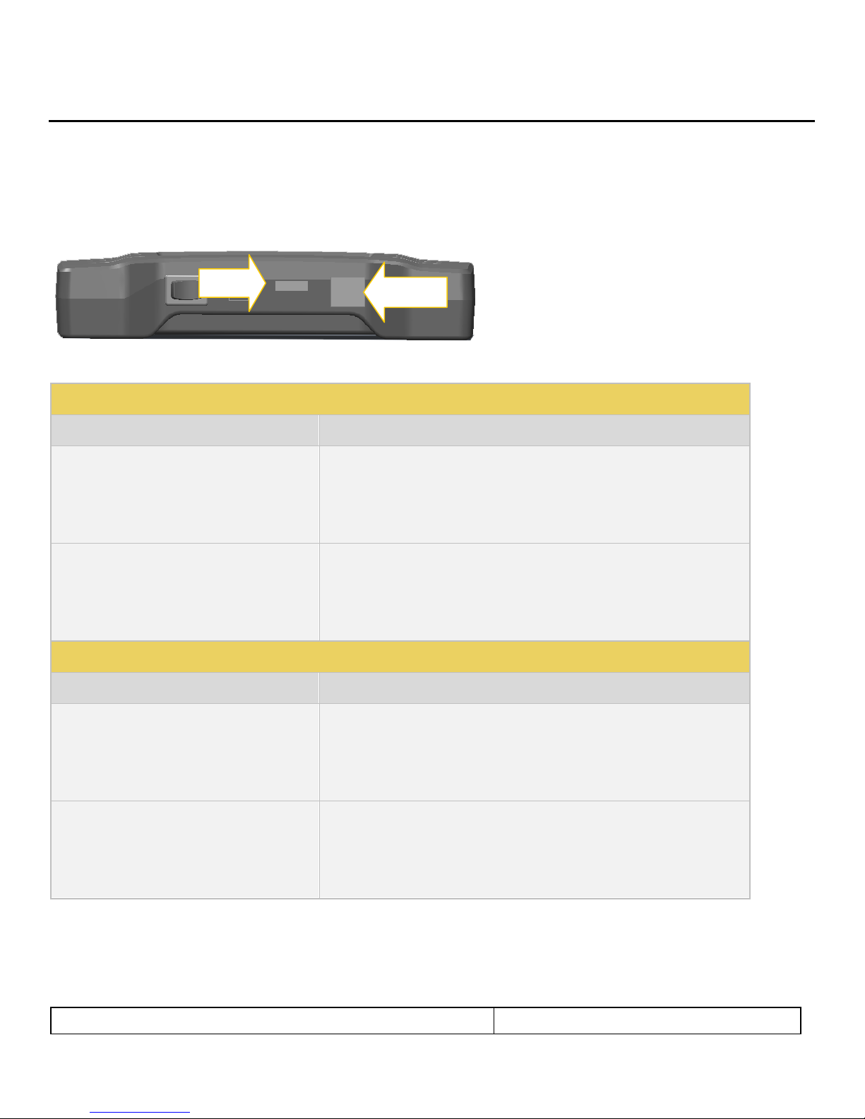
Table 2-3: 280G Administrative Interfaces
USB (micro) – Located on bottom edge
Used for command line interface. Not currently supported.
Micro SD slot – Located on bottom edge
Uses a micro SD or micro SDHC card
Used for file transfer:
- Upgrading the 280
- Transferring files such as EDID and Reports
Table 2-4: 280A Administrative Interfaces
USB (micro) – Located on bottom edge
Used for command line interface. Not currently supported.
Micro SD slot – Located on bottom edge
Uses a micro SD or micro SDHC card
Used for file transfer:
- Upgrading the 280
- Transferring files such as EDID and Reports
USB
SD Slot
2.2 Administrative Interfaces
Each 280 unit is equipped with a micro USB interface and a micro SD card slot. These interfaces are located on the
bottom edge of the 280G and the 280A as indicated in the illustration below:
The functions of the micro USB and the Micro SD card slot are described in the table below.
IMPORTANT NOTE ON MICRO SD CARD USAGE: The micro SD Card has to be inserted with the connector foils up as
shown below.
280 Test Set – Quick Start Guide Page 8
May 11, 2018
Revision 5
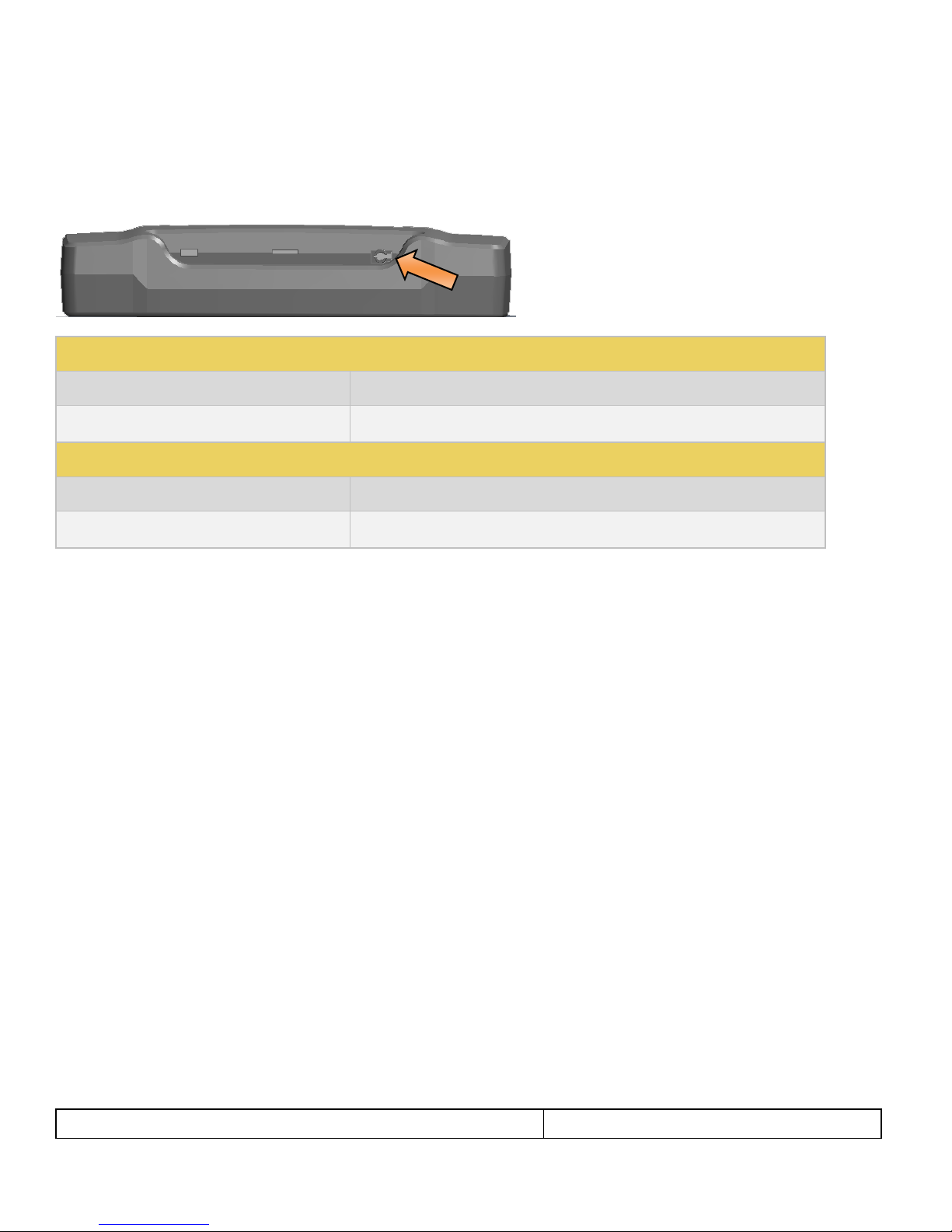
Table 2-4: 280G Audio Input Jack
Bottom Edge Panel
Description
3.5 mm analog audio input jack
Used for injecting audio into the outgoing HDMI or HDBaseT stream.
Table 2-5: 280A Audio Output Jack
Bottom Edge Panel
Description
3.5 mm analog audio output jack
Used for extracting audio to a speaker, headphone or ear buds.
2.3 Audio Jacks
There is a 3.5 mm analog audio jack on both the 280G and the 280A units. These audio jacks are located on the same
place on the bottom edge of the 280G and 280A chassis as shown below. The description and function of these jacks are
provided in the table below.
280 Test Set – Quick Start Guide Page 9
May 11, 2018
Revision 5
3 General Operation
This section describes power up, power usage and general operation.
3.1 Power Considerations
The 280 Test Set has a rocker style power switch on the back panel. Refer to the photo below.
The 280G and 280A are portable battery powered test instruments. They are equipped with rechargeable batteries.
Typically, you can use the 280 instruments on batteries for about 4-6 hours after a full charge. Teledyne LeCroy
recommends that you set the screen brightness to the minimum level required. Turn the unit off when not in use.
The 280G and 280A are Test Set is supplied with a 12V DC power supply and charger with an associated line cord.
Important Notes about power usage and status:
Monitor the battery meter on the lower right.
A green indication or partial green indication shows the battery is being charged.
A blue color with an electrical charge icon indicates that the device is being powered through the wall charger.
Fully charge the 280 units overnight.
Do not continue using the 280 units from battery power when the battery meter indicates that the batteries are
exhausted.
The following screen shows a charging battery condition.
The following example shows a nearly charged battery condition while the unit is running on batteries.
280 Test Set – Quick Start Guide Page 10
May 11, 2018
Revision 5
The following example shows a low battery condition.
3.2 Convenient Handle
The 280 units have a handle for convenient carrying. This is depicted in the illustration below.
280 Test Set – Quick Start Guide Page 11
May 11, 2018
Revision 5
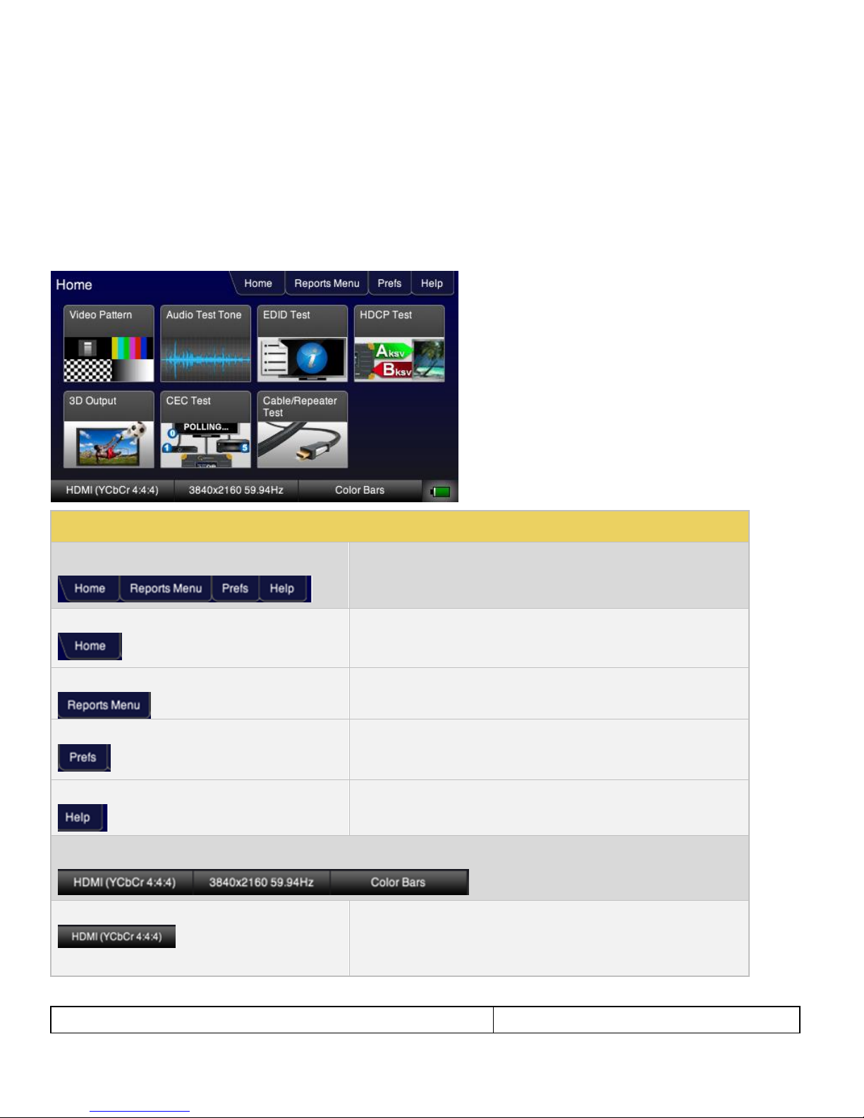
Table 3-1: 280G GUI Component
Top Panel
Description
Home
Activation button that returns to the Home screen.
Reports Menu
Activation button that provides access to the Reporting function.
Prefs (Preferences)
Activation button that provides access to control the screen brightness.
Help
Activation button that provides current version information and firmware
upgrades.
Lower Status Panel Description
Signal Type
Provides status of the selected Signal Type being transmitted. The signal
type (HDMI or HDBaseT) are given along with the colorimetry and
sampling. This also serves as an activation button that will navigate you
to the Signal Type screen to set the signal type.
3.3 Touch Screen User Interface
The 280G and 280A have color touch screen user interface with a screen display resolution of 480 by 272. A single touch
will activate an item on the screen or take you down to a lower level menu. A + indicates that you have to double touch to
navigate down to a lower level menu.
Note: Teledyne LeCroy recommends using a stylus or suitable plastic item with a blunt end to activate the buttons on the
280 screen. Selecting with your finger is sufficient however a stylus is preferable. You should not expect a similar touch
response that you have with a mobile phone.
280G User Interface
280 Test Set – Quick Start Guide Page 12
May 11, 2018
Revision 5
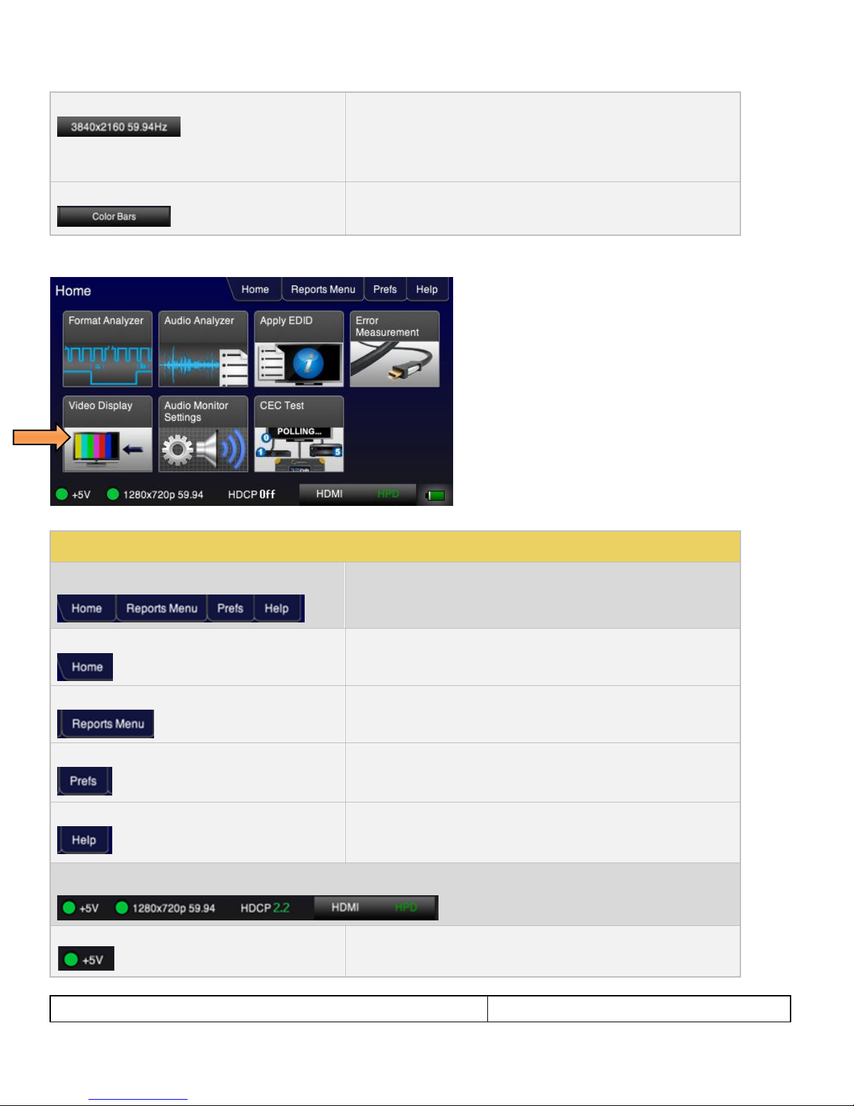
Format
Provides the status of the current format being transmitted. The active
horizontal and vertical pixels, progressive or interlaces (p or i) and the
frame rate, e.g. 59.94, 30, 24, etc. are given. This is also an activation
button that will navigate to the Signal Type screen to enable you to set the
format resolution.
Test Pattern
Indicates the active test pattern/. Also serves as an activation button and
navigates you to the Test Pattern selection screen to choose a test pattern.
Table 3-2: 280A GUI Components
Top Panel
Description
Home
Activation button that returns to the Home screen.
Reports Menu
Activation button that provides access to the Reporting function.
Prefs (Preferences)
Activation button that provides access to control the screen brightness.
Help
Activation button that provides current version information and firmware
upgrades.
Lower Status Panel Description
+5V
+5V Status indicator. The green LED indicates that +5V is being
received. No light when insufficient +5V.
280A User Interface
280 Test Set – Quick Start Guide Page 13
May 11, 2018
Revision 5
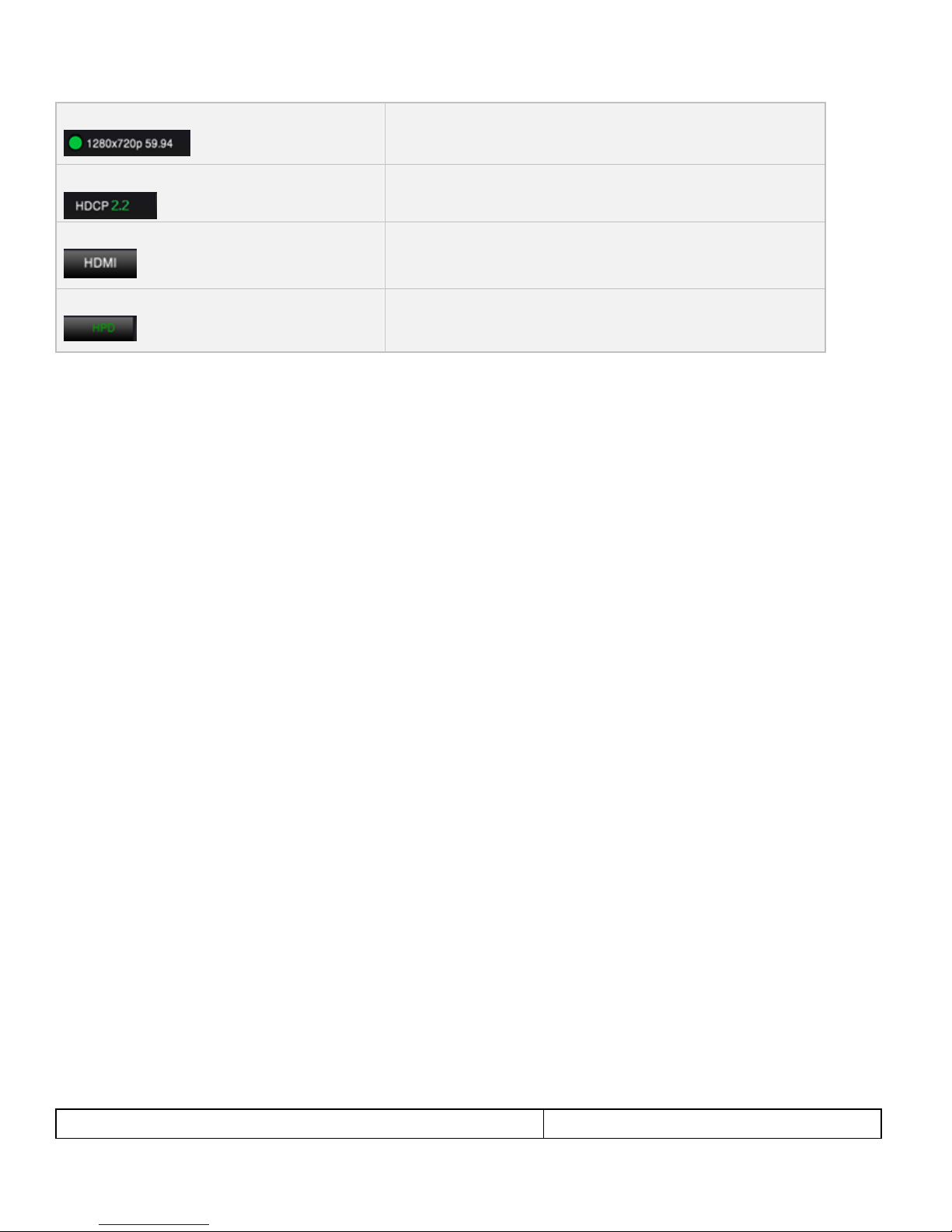
Resolution
The active horizontal and vertical pixels, progressive or interlaces (p or i)
and the frame rate, e.g. 59.94, 30, 24, etc.
HDCP Status
Either Off, 1.x or 2.2
Active Interface
Either HDMI or HDBaseT
HPD
Hot Plug toggle. Operation: Press and release to put in depressed state,
and then press and release again to cause a hot plug toward the upstream
source.
280 Test Set – Quick Start Guide Page 14
May 11, 2018
Revision 5
4 Using the 280G to Run Video and Audio Tests on Displays and TVs
This Chapter provides procedures for using the 280G to run video and audio tests on high definition sink devices such as
HDTVs and projectors but you can also run tests downstream on entire distribution networks. The following signal types
are supported.
HDMI
HDBaseT
4.1 Making Physical Connections
The first step in testing a sink device is to make the physical connections between the 280G and the device(s) under test.
Connecting the 280G to the Display Device
Use the following procedures to make the physical connections from the 280G to the display device under test.
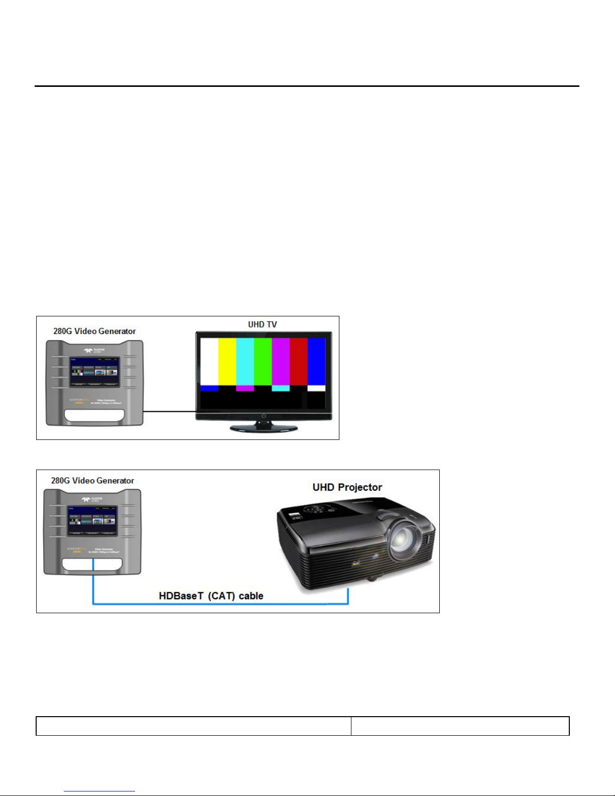
1. Make the cable connection between the 280G video output connector (e.g. HDMI OUT or HDBaseT OUT) and the
input connector of the sink device under test.
The following illustrations depict typical test configurations.
280G connected to an UHD TV via an HDMI cable
280G connected to a projector via HDBaseT
280 Test Set – Quick Start Guide Page 15
May 11, 2018
Revision 5
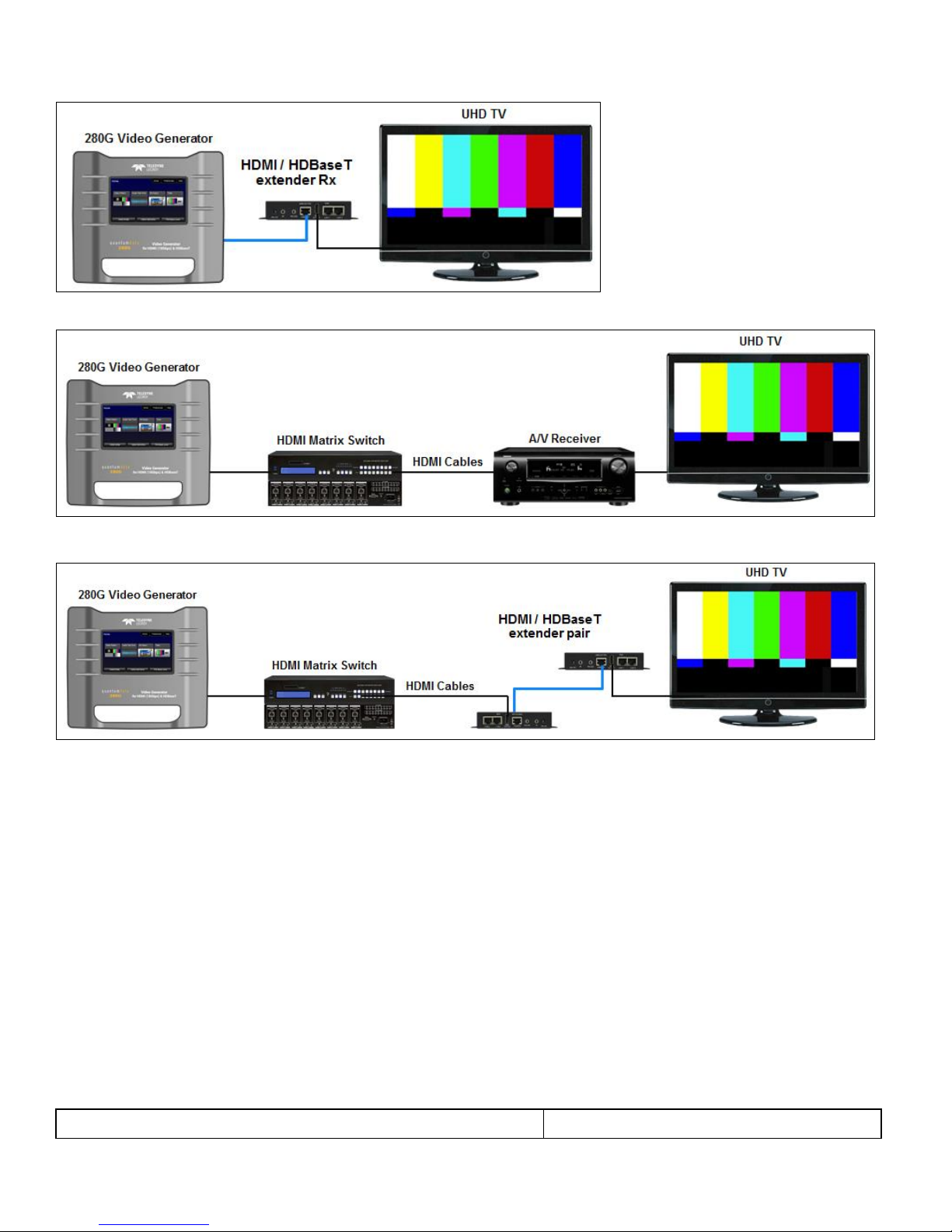
280G connected to an HDBaseT Extender via HDBaseT then to a UHD TV
280G connected to an HDMI network of devices
280G connected to an HDMI/HDBaseT distribution network
280 Test Set – Quick Start Guide Page 16
May 11, 2018
Revision 5
4.2 Selecting a Signal Type and Resolution
After making the physical connections between the 280G and the display device under test you will need to select the
Signal Type, Resolution and Frame Rate for the sink device under test.
Selecting Video Formats
The procedures below describe how to select the active signal type.
1. Power up the 280G using the rocker switch on the top edge. Review the guidelines for battery usage above.
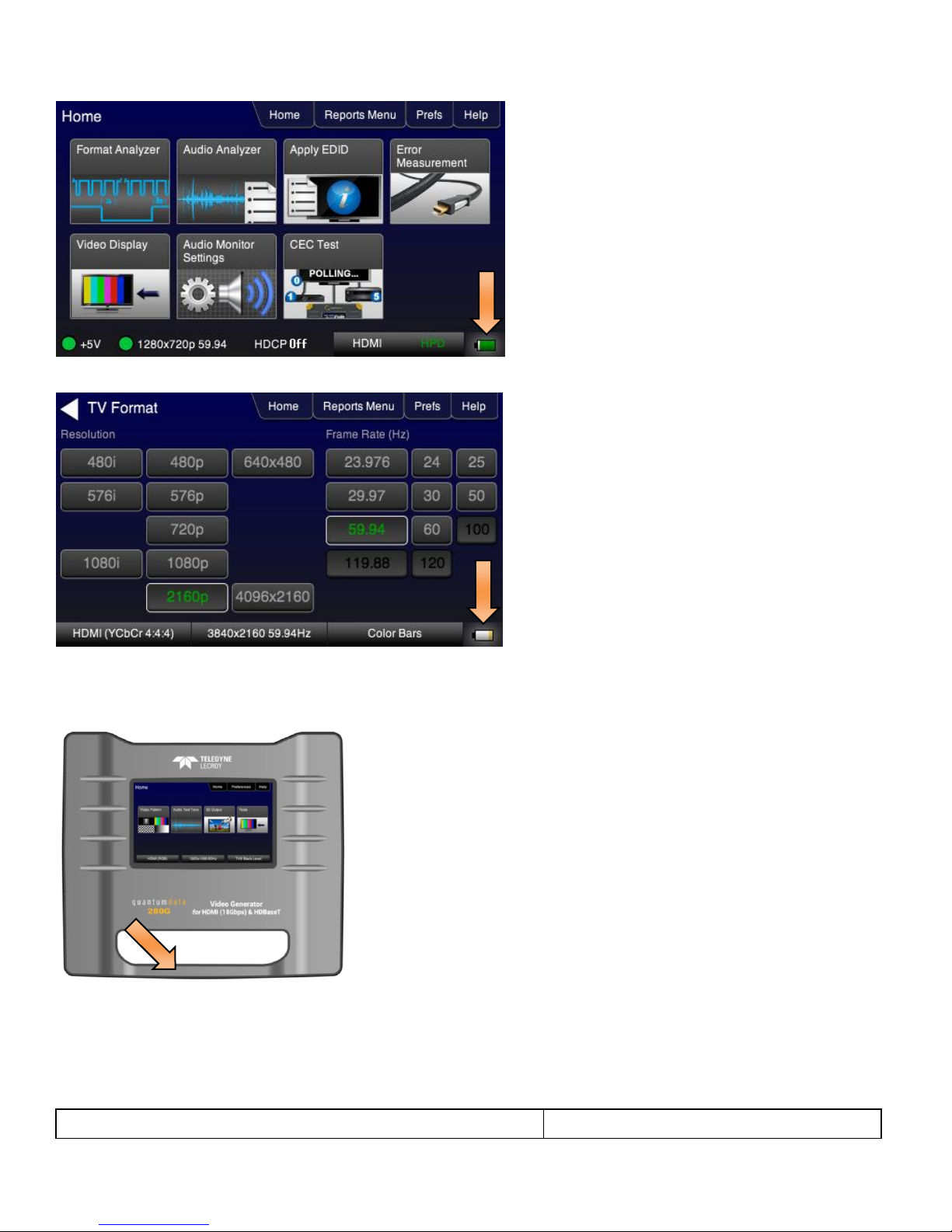
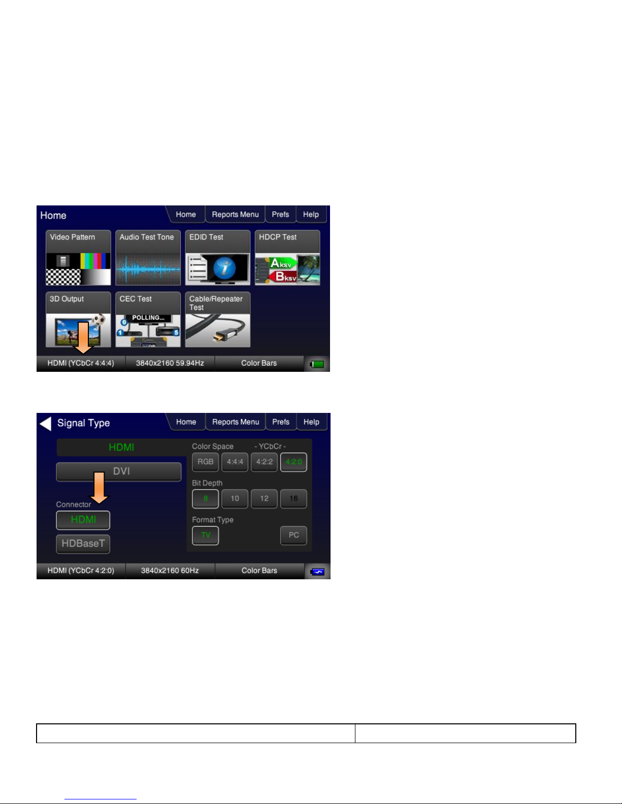
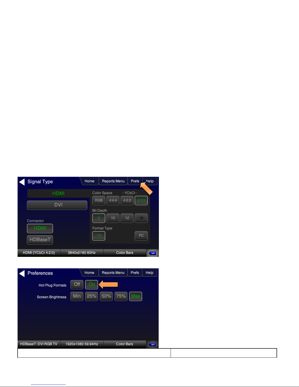
2. From the Home page touch select the Signal Type activation button on the bottom status panel as indicated below.
3. Touch select the interface type (Connector), HDMI or HDBaseT.
Example shows HDMI being selected. You can also select DVI once HDMI is selected.
280 Test Set – Quick Start Guide Page 17
May 11, 2018
Revision 5
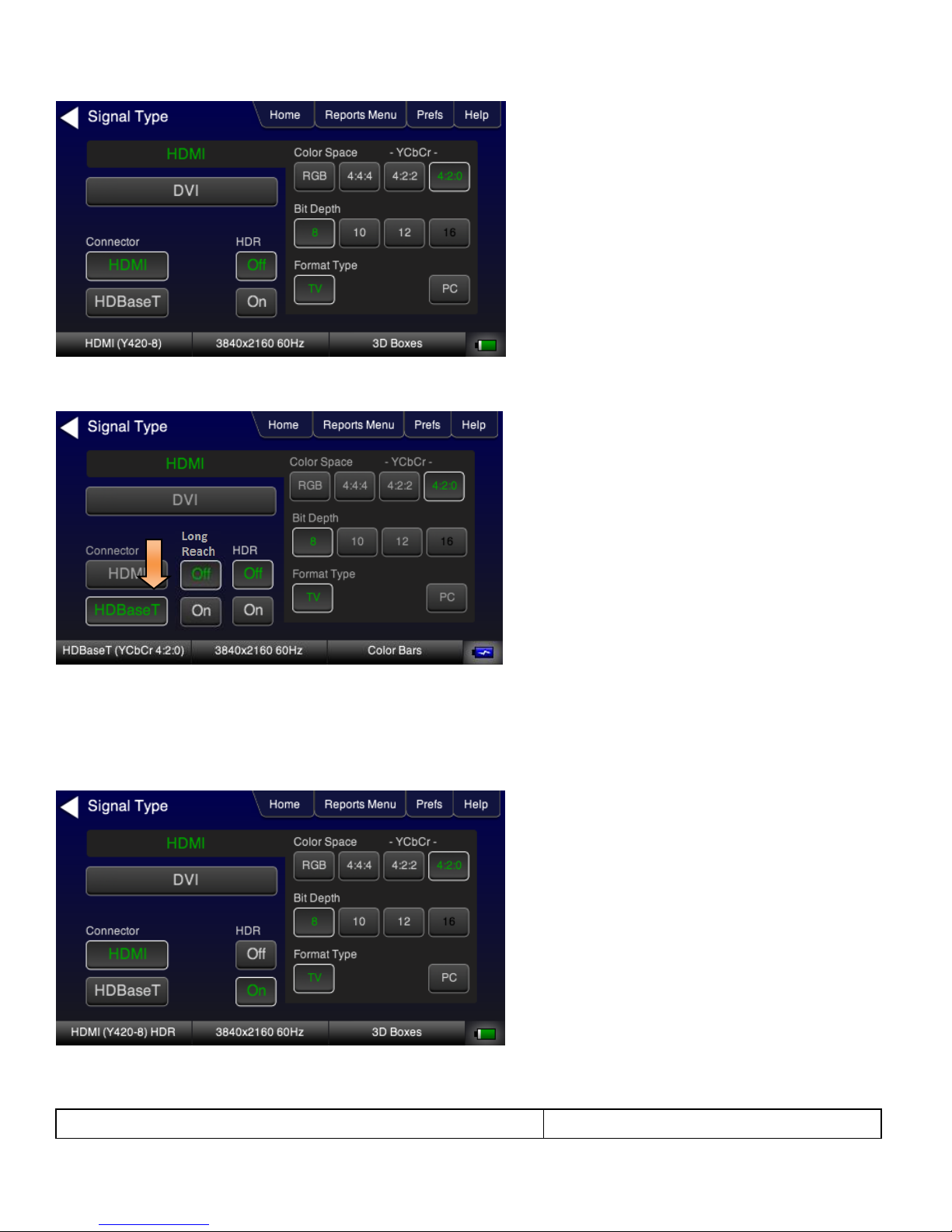
Example shows HDBaseT being selected.
HDBaseT has “Long Reach” mode which enables transmission of a 1080p60 signal to go 170 meters on Cat7 cabling.
4. Touch select the options for the Signal Type such as the Color Space, Sampling, Bit Depth and Format Type in
accordance with your requirements.
5. Touch select the options for the Signal Type such as the HDR in accordance with your requirements. Example below
shows HDR selected.
Selecting an HDMI Resolution and Frame Rate
280 Test Set – Quick Start Guide Page 18
May 11, 2018
Revision 5
The procedures below describe how to select the resolution.
When you make a physical connection to an HDMI HDTV (or an HDBaseT input port), a hot plug event will occur. There
are two modes the 280G can be set in when testing HDMI sink devices that determine how the 280G responds to this hot
plug event:
Hot plug formats On – This mode will cause the 280G to select a preferred timing in the EDID of the connected
sink device. Supported formats will be indicated in white text. You can select formats that are not supported but
the frame rates of unsupported frame rates will be shown with red text. You will be able to select other formats
that are not supported by the sink device.
Hot plug formats Off – This mode will show all supported formats on the 280G in white text.
For the HDMI and HDBaseT formats, there are color codes that are applied to the Resolution and Frame Rate selections.
The following is a summary of their meaning:
A Resolution or Frame Rate with white lettering but with no outline – a Resolution or Frame Rate that appears in the
EDID and has a short video descriptor associated with it.
A Frame Rate with green lettering and with white outline – The Frame Rate that is currently selected.
A Frame Rate with red lettering but with no outline – The Frame Rate is not supported by the EDID for that
Resolution.
A Frame Rate(s) with green lettering and with white outline – The Frame Rate along with the currently selected
Resolution that is the “preferred” timing.
A Frame Rate with black lettering but with no outline – The Frame Rate is not supported by the standard for the
selected resolution.
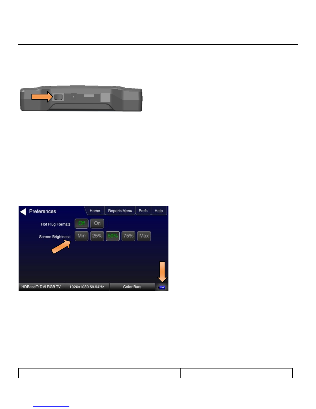
1. Select the Preferences from the 280G top level menu.
2. Select the Hot Plug Formats mode to On or Off as desired. Refer to the screen below.
280 Test Set – Quick Start Guide Page 19
May 11, 2018
Revision 5
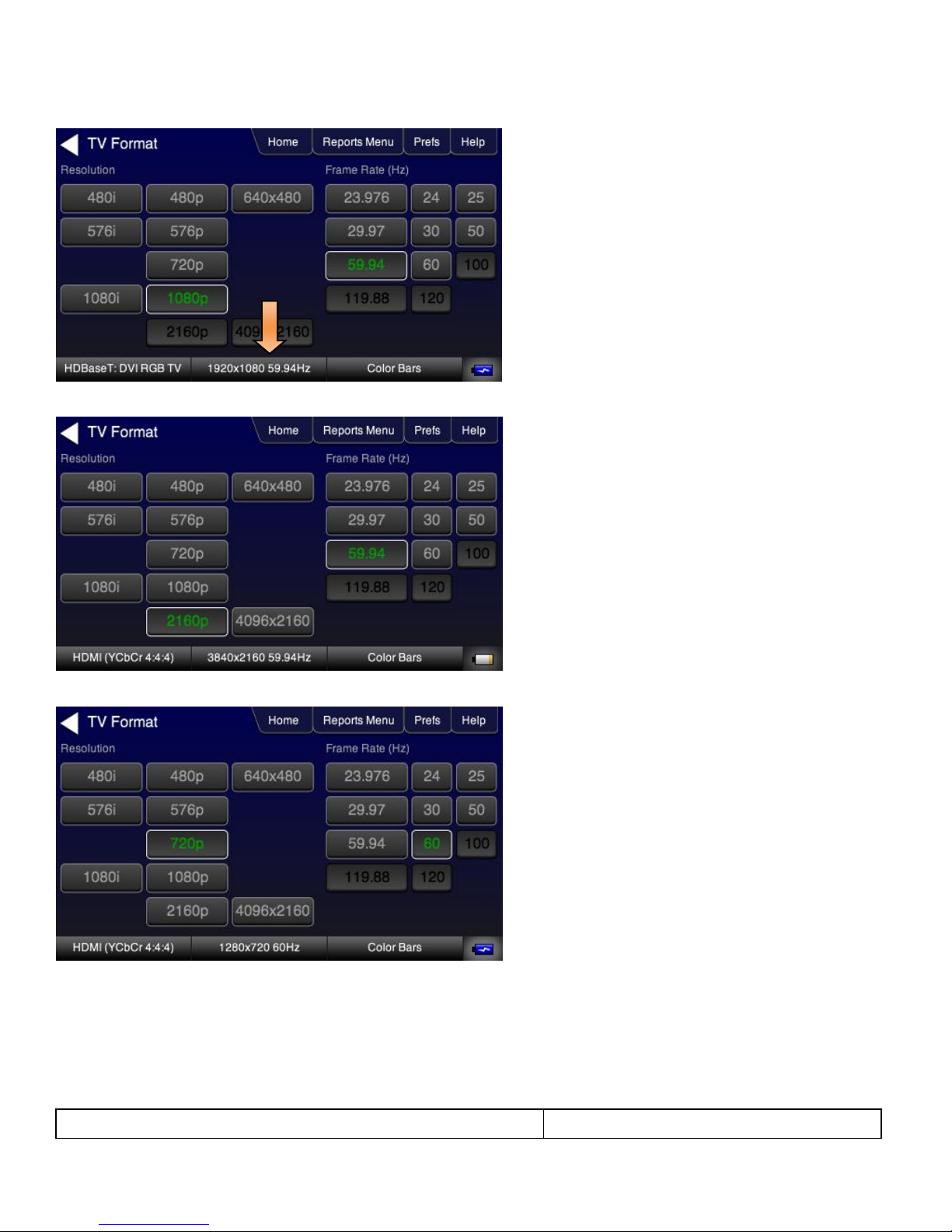
3. Touch select the resolution and frame rate (middle button on the bottom panel). Refer to the figures below.
The following is an example with a 4K format selected.
The following is an example when Hot Plug formats is turned on for 720p formats.
The following screen shows red text where a format is not supported in the EDID received at the 280G. Note that you can
select these other formats.
 Loading...