

Page 1
Operator’s
Manual
ArbStudio
Arbitrary Waveform
Generator
Page 2

Page 3

ArbStudio
Arbitrary Waveform Generator
Operator’s Manual
January 2013
Page 4

© 2013 Teledyne LeCroy, Inc. All rights reserved.
Unauthorized duplication of Teledyne LeCroy documentation materials other than
for internal sales and distribution purposes is strictly prohibited. However, clients
are encouraged to distribute and duplicate Teledyne LeCroy documentation for
their own internal educational purposes.
ArbStudio and Teledyne LeCroy are registered trademarks of Teledyne LeCroy.
Windows is a registered trademark of Microsoft Corporation. Other product or
brand names are trademarks or requested trademarks of their respective holders.
Information in this publication supersedes all earlier versions. Specifications are
subject to change without notice.
Warranty
NOTE: THE WARRANTY BELOW REPLACES ALL OTHER WARRANTIES, EXPRESSED OR IMPLIED,
INCLUDING BUT NOT LIMITED TO ANY IMPLIED WARRANTY OF MERCHANTABILITY, FITNESS, OR
ADEQUACY FOR ANY PARTICULAR PURPOSE OR USE. TELEDYNE LECROY SHALL NOT BE LIABLE FOR ANY
SPECIAL, INCIDENTAL, OR CONSEQUENTIAL DAMAGES, WHETHER IN CONTRACT OR OTHERWISE. THE
CUSTOMER IS RESPONSIBLE FOR THE TRANSPORTATION AND INSURANCE CHARGES FOR THE RETURN
OF PRODUCTS TO THE SERVICE FACILITY. TELEDYNE LECROY WILL RETURN ALL PRODUCTS UNDER
WARRANTY WITH TRANSPORT PREPAID.
The ArbStudio is warranted for normal use and operation, within specifications, for a period of three
years from shipment. Teledyne LeCroy will either repair or, at our option, replace any product returned
to one of our authorized service centers within this period. However, in order to do this we must first
examine the product and find that it is defective due to workmanship or materials and not due to
misuse, neglect, accident, or abnormal conditions or operation.
Teledyne LeCroy shall not be responsible for any defect, damage, or failure caused by any of the
following: a) attempted repairs or installations by personnel other than Teledyne LeCroy
representatives or b) improper connection to incompatible equipment, or c) for any damage or
malfunction caused by the use of non-Teledyne LeCroy supplies. Furthermore, Teledyne LeCroy shall
not be obligated to service a product that has been modified or integrated where the modification or
integration increases the task duration or difficulty of servicing the instrument. Spare and replacement
parts, and repairs, all have a 90-day warranty.
The instrument's firmware has been thoroughly tested and is presumed to be functional. Nevertheless,
it is supplied without warranty of any kind covering detailed performance. Products not made by
Teledyne LeCroy are covered solely by the warranty of the original equipment manufacturer.
922244-00 Rev A
January 2013
Page 5

Operator’s Manual
922244-00 Rev A
i
TABLE OF CONTENTS
Welcome .................................................................................................... 1
Minimum System Requirements ................................................................. 1
Suggested System Requirements ................................................................ 2
Package Contents ........................................................................................ 2
Safety Instructions ...................................................................................... 3
Symbols ........................................................................................................ 3
Precautions .................................................................................................. 3
Operating Environment ............................................................................... 4
Cooling ......................................................................................................... 5
Cleaning ....................................................................................................... 5
Calibration.................................................................................................... 5
Power ........................................................................................................... 6
Front Panel ................................................................................................... 7
Back Panel .................................................................................................... 8
Getting Started with ArbStudio ................................................................. 10
Overview .................................................................................................... 10
Software and Driver Installation ................................................................ 10
Initial ArbStudio Software Interfaces ........................................................ 17
Setup Examples and Common Tasks ......................................................... 23
Channel Settings ....................................................................................... 32
Overview .................................................................................................... 32
Channel Settings - The General Tab ........................................................... 33
Channel Settings - The Run Mode Tab (Waveform Sequence) ................. 35
Channel Settings - Run Mode Tab (Modulation) ....................................... 39
Channel Settings - The Trigger IN Tab........................................................ 40
Channel Settings - Trigger OUT Tab ........................................................... 42
Setup System ............................................................................................ 43
Setup Device ............................................................................................. 45
Timing Tab ................................................................................................. 45
B
Page 6

ArbStudio
ii
922244-00 Rev A
Channel Out Math Tab .............................................................................. 47
Trigger OUT Math Tab............................................................................... 48
Digital I/O Tab ........................................................................................... 49
Strobe Tab ................................................................................................. 50
The Waveform Sequencer - Analog ........................................................... 51
Creating Standard and Advanced Waveforms .......................................... 51
Waveform Graph Toolset .......................................................................... 59
Advanced Waveform Editing .................................................................... 61
Segment Editing ........................................................................................ 63
Component Type ....................................................................................... 66
Segment Parameters ................................................................................. 67
Waveform Parameters .............................................................................. 67
Markers ..................................................................................................... 71
Sequencing Analog Waveforms ................................................................ 73
Additional Waveform Sequencer Settings/Tools ...................................... 75
Modulation Editor - Arbitrary/DDS ............................................................ 83
Overview ................................................................................................... 83
Hardware Resources ................................................................................. 83
Edit Modulation Rule ................................................................................ 84
Modulation Type ....................................................................................... 84
Modulating Table ...................................................................................... 85
Command Bar ........................................................................................... 85
Modulation Entry Editor ........................................................................... 86
Modulation Segment Editor ...................................................................... 87
Amplitude Profile Editor (DDS) .................................................................. 89
Limits Settings ........................................................................................... 90
Profile Command ...................................................................................... 90
Digital Pattern Generator - Sampler (Optional) .......................................... 91
Pattern (Sampling and Acquisition) Settings ............................................ 92
Example - Digital Pattern Generator Setup ............................................ 103
Page 7

Operator’s Manual
922244-00 Rev A
iii
Waveform Sequencer - Digital Pattern .................................................... 110
Signal Definitions ..................................................................................... 125
Acquisition - Using The Pattern Generator as a Sampler ........................ 127
Probes ...................................................................................................... 137
The Pulse Width Modulation (PWM) Generator Workspace ..................... 140
Pulse Definition Area ............................................................................... 141
Duty Cycle Modulation Area .................................................................... 142
Control Area ............................................................................................. 143
Example - PWM Setup ............................................................................. 145
"How do I" Scenario Details .................................................................... 146
Creating Your First Analog Waveform ..................................................... 147
Creating a Sequence of Waveforms ........................................................ 151
Creating an Amplitude Modulated Waveform ........................................ 155
Creating a Frequency Modulated Waveform .......................................... 161
Creating a Phase Modulated Waveform ................................................. 166
Importing a Waveform from an Oscilloscope .......................................... 171
Creating Digital Waveforms ..................................................................... 175
Creating Waveforms Using Formulas ....................................................... 181
Overview .................................................................................................. 181
Steps to Creating Advanced Waveform Components Using Formulas ... 182
Exponentially Decaying Sine Wave .......................................................... 187
Ramp ........................................................................................................ 188
Rising Exponential .................................................................................... 189
Decaying Exponential .............................................................................. 190
Sine .......................................................................................................... 191
Linear Amplitude Sweep of a Sine Wave ................................................. 192
Frequency Modulation ............................................................................ 193
Phase Modulation .................................................................................... 194
Linear Frequency Sweep .......................................................................... 195
Gaussian Pulse ......................................................................................... 196
B
Page 8

ArbStudio
iv
922244-00 Rev A
Lorentzian Pulse ...................................................................................... 197
Amplitude Modulated Sine ..................................................................... 198
Full-Wave Rectified Sine ......................................................................... 199
Half-Wave Rectified Sine......................................................................... 200
Reference ............................................................................................... 201
Certifications ........................................................................................... 201
Windows® License Agreement ................................................................ 203
End-User License Agreement for Teledyne LeCroy® X-Stream Software 203
Contact Teledyne LeCroy ........................................................................ 215
Index ...................................................................................................... 216
Page 9

Operator’s Manual
922244-00 Rev A
1
Welcome
Thank you for purchasing a Teledyne LeCroy ArbStudio.
ArbStudio is a series of high performance Arbitrary Waveform Generators
(AWG) consisting of 2 and 4 channel models, 2 Mpts/ch memory, 16 bit
resolution and a maximum sample rate of 1 GS/s. Some models provide the
ability to generate 18 or 36 channel digital patterns and all models can be
operated in true arbitrary mode or Direct Digital Synthesis (DDS) mode.
We truly hope these materials provide increased comprehension when
using Teledyne LeCroy's fine products.
Sincerely,
David C. Graef
Teledyne LeCroy Corporation
Vice President and Chief Technology Officer
Minimum System Requirements
Operative system Microsoft™ Windows® 2000, Windows® XP,
Pentium® III processor.
512 MBytes RAM.
150 MBytes hard disk available space for software set-up.
Video resolution 800 X 600.
USB 2.0 or 1.1 connections.
B
Windows® Vista 32 Bit Version, Windows® 7 32 Bit Version.
Page 10

ArbStudio
2
922244-00 Rev A
Suggested System Requirements
Operative system Microsoft™ Windows® XP, Windows® Vista 32 Bit
Version, Windows® 7 32 Bit Version.
Pentium® IV processor.
1.5 GBytes RAM.
Video resolution 1024 X 768.
USB 2.0 connection.
Package Contents
The standard ArbStudio 1102/1104 package includes the following:
ArbStudio 1102/1104 Arbitrary Waveform Generator
Standard USB 2.0 Cable
Power Supply Adapter
Power Cord
Installation CD containing the ArbStudio Software setup files,
ArbStudio Function Generator software, Drivers, and the Getting
Started Manual.
Performance/Calibration Certificate
ArbStudio Introduction and Compliance document
-D Models include a ‘Digital Leadset’
Page 11
Operator’s Manual
922244-00 Rev A
3
CAUTION of damage to instrument, or WARNING of hazard to
health. Attend to the accompanying information to protect
against personal injury or damage. Do not proceed until
conditions are fully understood and met.
WARNING. Risk of electro-shock.
Measurement ground connection.
Safety (protective) ground connection.
Alternating Current.
Safety Instructions
This section contains instructions that must be observed to keep the
instrument operating in a correct and safe condition. You are required to
follow generally accepted safety procedures in addition to the precautions
specified in this section. The overall safety of any system incorporating
this instrument is the responsibility of the assembler of the system.
Symbols
These symbols appear on the instrument's front or rear panels and in its
documentation to alert you to important safety considerations.
Precautions
Use proper power cord. Use only the power cord shipped with this
instrument and certified for the country of use.
Maintain ground. This product is grounded through the power cord
grounding conductor. To avoid electric shock, connect the external
AC adapter only to a grounded mating outlet.
Connect and disconnect properly. Do not connect/disconnect
probes or test leads while they are connected to a voltage source.
B
Page 12

ArbStudio
4
922244-00 Rev A
Observe all terminal ratings. Do not apply a voltage to any input
that exceeds the maximum rating of that input. Refer to the front of
the instrument for maximum input ratings.
Use only within operational environment listed. Do not use in wet
or explosive atmospheres.
Use indoors only.
Keep product surfaces clean and dry.
Do not block the cooling vents. Leave a minimum six-inch (15 cm)
gap between the instrument and the nearest object. Keep the
underside clear of papers and other objects.
Do not remove the covers or inside parts. Refer all maintenance to
qualified service personnel.
Do not operate with suspected failures. Do not use the product if
any part is damaged. Obviously incorrect measurement behaviors
(such as failure to calibrate) might indicate impairment due to
hazardous live electrical quantities. Cease operation immediately
and sequester the instrument from inadvertent use.
Operating Environment
The instrument is intended for indoor use and should be operated in a
clean, dry environment. Before using this product, ensure that its operating
environment is maintained within these parameters:
Temperature: 0 °C to 50 °C
NOTE: Power Supply Adapter for ArbStudio 1104 is rated for 40 °C max.
Humidity: Maximum relative humidity 80% (non-condensing) for
temperatures up to 40 °C decreasing linearly to 50 % relative humidity at
50 °C.
Altitude: Up to 10,000 ft (3,048 m) at or below 30 °C.
Page 13
Operator’s Manual
922244-00 Rev A
5
Cooling
The instrument relies on forced air cooling with internal fans and vents.
Take care to avoid restricting the airflow to any part of the instrument.
Around the sides and rear, leave a minimum of 15 cm (6 inches) between
the instrument and the nearest object. At the bottom, the instrument feet
(up or down) provide adequate clearance.
CAUTION. Do not block instrument vents. Always keep the area
beneath the instrument clear of paper and other items.
The instrument also has internal fan control circuitry that regulates the fan
speed based on the ambient temperature. This is performed automatically
after start-up.
Cleaning
Clean only the exterior of the instrument using a damp, soft cloth. Do not
use harsh chemicals or abrasive elements. Under no circumstances
submerge the instrument or allow moisture to penetrate it. Avoid electric
shock by unplugging the power cord from the AC outlet before cleaning.
CAUTION. Do not attempt to clean internal parts. Refer to qualified
service personnel.
Calibration
The recommended calibration interval is one year. Calibration should be
performed by qualified personnel only.
CAUTION. It is required that all inputs be removed from the
instrument prior to performing a manual calibration.
Schedule an annual factory calibration as part of your regular maintenance.
Extended warranty, calibration, and upgrade plans are available for
purchase. Contact your Teledyne LeCroy sales representative or
customersupport@teledynelecroy.com to purchase a service plan.
B
Page 14

ArbStudio
6
922244-00 Rev A
Power
Power Consumption
35 VA (35 W) Max
AC Power Source
For External AC Adapter:
100 to 240 VAC (+/-10%) at 45-66 Hz
No manual voltage selection is required because the external AC Adapter
automatically adapts to line voltage.
Standby Power
The Power (Standby) button controls the operational state of the
instrument. Press the button to switch the instrument On or into Standby
mode (Off).
Always use the Power button to execute a proper shut down process and
preserve settings before powering down.
Page 15
Operator’s Manual
922244-00 Rev A
7
Hardware Inputs and Outputs
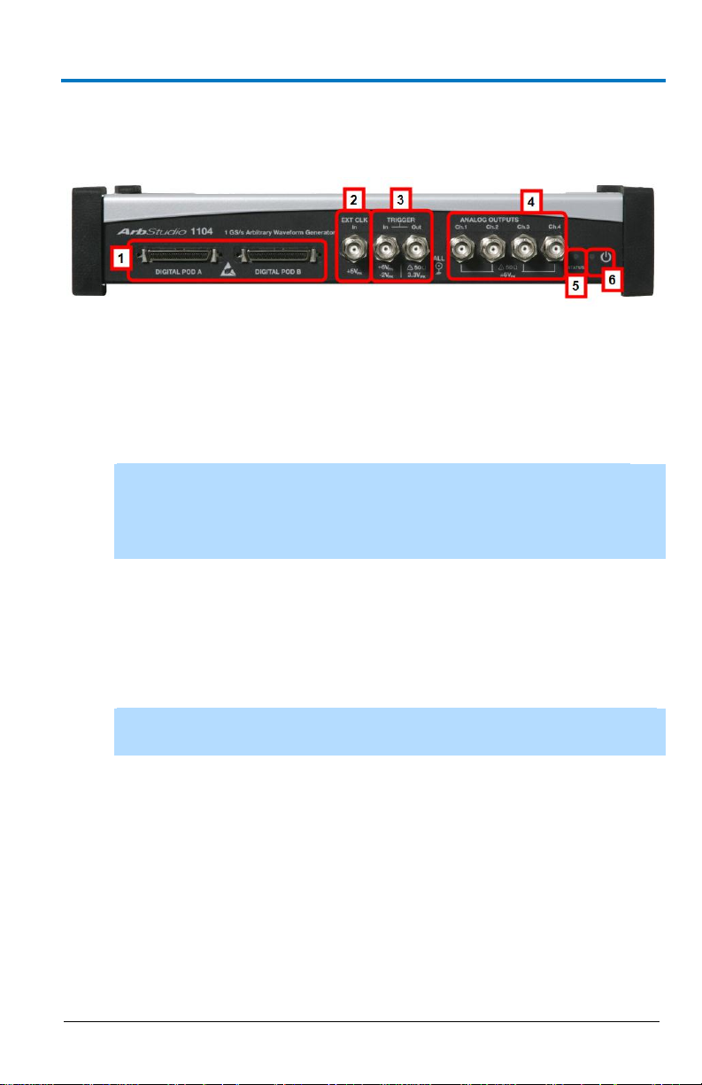
Front Panel
Figure 3-1. ArbStudio 1104 model with a POD B connector and two additional
Channel Outputs. Although digital pods appear on all models, they are only
active on 1102D and 1104D models.
DIGITAL POD A / DIGITAL POD B
1. DIGITAL POD A / DIGITAL POD B Probe connectors
NOTE: DIGITAL POD B is only available on ArbStudio 1104. POD A
and POD B are only active on 1102D and 1104D models. ArbStudio
1102 and 1104 can be upgraded to include the digital pattern
generator.
2. EXT CLK BNC input connector for external clock
3. TRIGGER
4. ANALOG OUTPUTS 12 V to 12 V BNC output connector
5. STATUS LED Indicates instrument power status
6. POWER-ON LED Indicates the power status of the instrument. The
B
Trigger Out - BNC output connector for Trigger OUT.
Trigger In - BNC input connector for Trigger IN.
NOTE: Ch3 and Ch4 are only available on ArbStudio 1104 and 1104D
models.
status led can be OFF, ON, or Blinking denoting the following
conditions:
OFF. The instrument is ON and connected to a PC, but drivers
have not been installed.
ON. The instrument is ON, connected to a PC, and correctly
configured.
Blinking. ArbStudio 1102/1104 is uploading firmware for
channels.
Page 16
ArbStudio
8
922244-00 Rev A
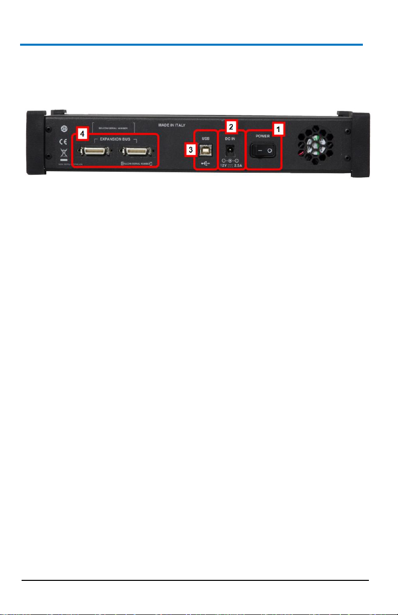
Back Panel
Numbered callouts on this image correspond with the following
descriptions.
1. POWER - The power switch.
2. DC IN - 12 V – 2.5 A DC connector.
3. USB - USB 2.0 connector.
4. EXPANSION BUS - The Expansion bus connector is located on the
rear panel of the ArbStudio 1104 and 1104D models only. Using the
appropriate expansion cable, up to 8 total 4 Channel ArbStudio units
may be connected.
It is possible to have a system with up to 8 independent arbitrary
waveform generators, each with the ability to have a synchronized
trigger.
PLEASE NOTE THE FOLLOWING:
ArbStudio 1104 and 1104D units sharing the Expansion bus
must all be connected to the same controller (PC) via USB or
hub.
If more than one ArbStudio 1104 or 1104D are connected to
the same PC, they must also be linked through the Expansion
bus.
Making Expansion Bus Connections
In order to connect several ArbStudio 1104 or 1104D units you must first:
Connect the ArbStudio units using the Expansion bus.
Connect all ArbStudio units to a single PC by using an USB connector
or by using a HUB.
Ensure all ArbStudio units are correctly recognized by the operating
system.
Page 17

Operator’s Manual
922244-00 Rev A
9
When you launch the ArbStudio software, if all the correct connections are
made, the instruments are shown as connected together. The
interconnected instruments make up your complete ArbStudio system.
Removing Expansion Bus Connections
Before disconnecting or switching off the instrument, it must be removed
by left clicking the Safely Remove Hardware icon showing in the Windows
System Tray on your PC.
When your operating system eventually shows a Safely Remove Hardware
screen, select Safely remove Teledyne LeCroy ArbStudio, and then click
the Stop button.
NOTE: If the instrument is switched off or disconnected without performing
the proper safe removal process, the software may not operate correctly.
B
Page 18
ArbStudio
10
922244-00 Rev A
Getting Started with ArbStudio
Overview
This Getting Started section begins by providing essential installation
instructions for Drivers and Software. Then, the initial software interfaces
are introduced. Finally, Setup Examples and Common Tasks are provided to
bring you up to speed as fast as possible.
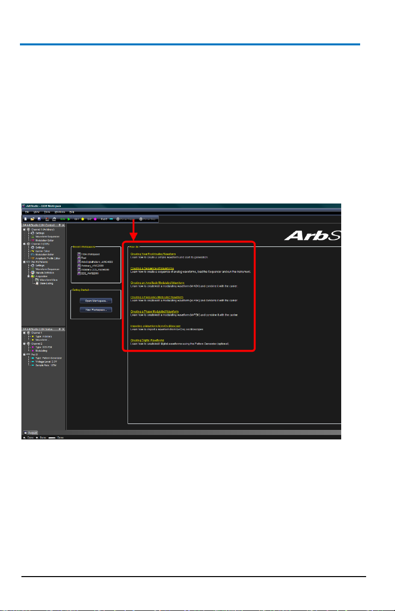
The How do I section of the ArbStudio Welcome screen contains links to
step-by-step explanations of standard functions and setups using your new
product.
These titles along with others provided here and in other locations of this
documentation provide accurate descriptions for regular tasks.
Software and Driver Installation
Insert the installation CD into your CD/DVD reader on your computer.
If the Welcome screen is not automatically shown, run the cdstart.exe file
on the root directory of the installation files.
Page 19
Operator’s Manual
922244-00 Rev A
11
The one installer guides you through proper setup of both the ArbStudio
software and necessary drivers for your computer as explained in the
following topics.
Software Installation
NOTE: The Microsoft .NET Framework 2.0 Run-Time Engine (or greater) is
required to run the ArbStudio 1102/1104 software properly.
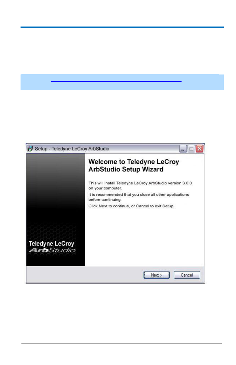
After inserting the installation CD into your CD/DVD reader, the Welcome
screen is eventually shown, click Install Teledyne LeCroy ArbStudio to start
setting up the software.
The ArbStudio Setup Wizard is then shown. Click Next to proceed with the
installation.
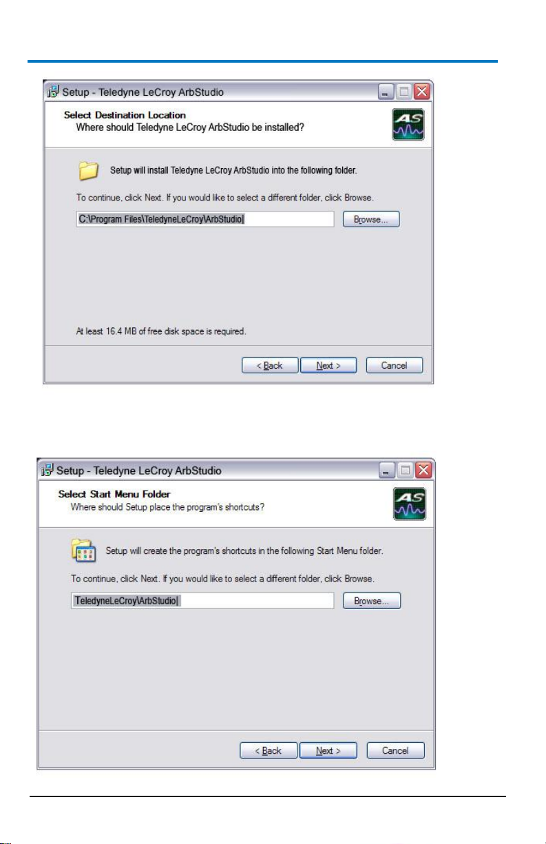
You can leave the default Installation Folder path, or specify a new location
and click Next.
B
Page 20
ArbStudio
12
922244-00 Rev A
Now, either leave the default Start Menu folder path, or specify a new
location and click Next.
Page 21
Operator’s Manual
922244-00 Rev A
13
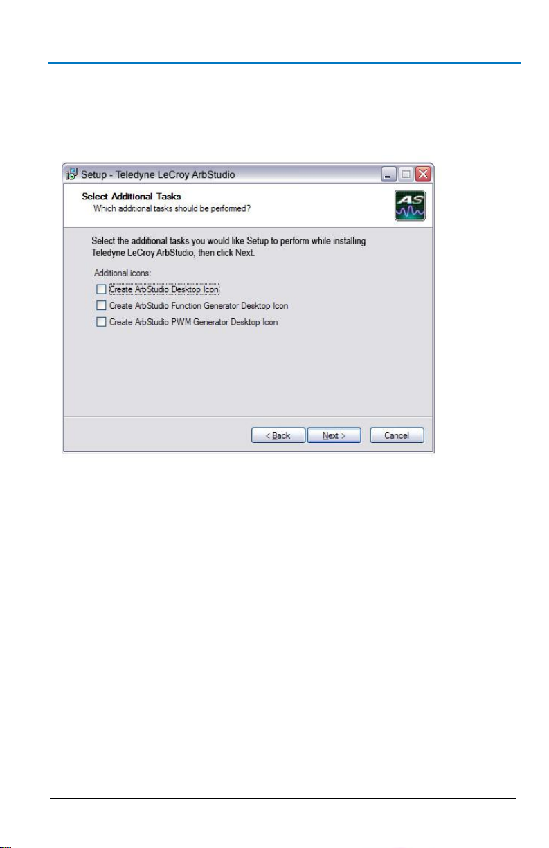
Use the next screen in the wizard to have the installation configure
Desktop shortcuts/icons for ArbStudio, ArbStudio Function Generator, and
ArbStudio PWM Generator. Mark the checkboxes for the desired tasks and
and click Next.
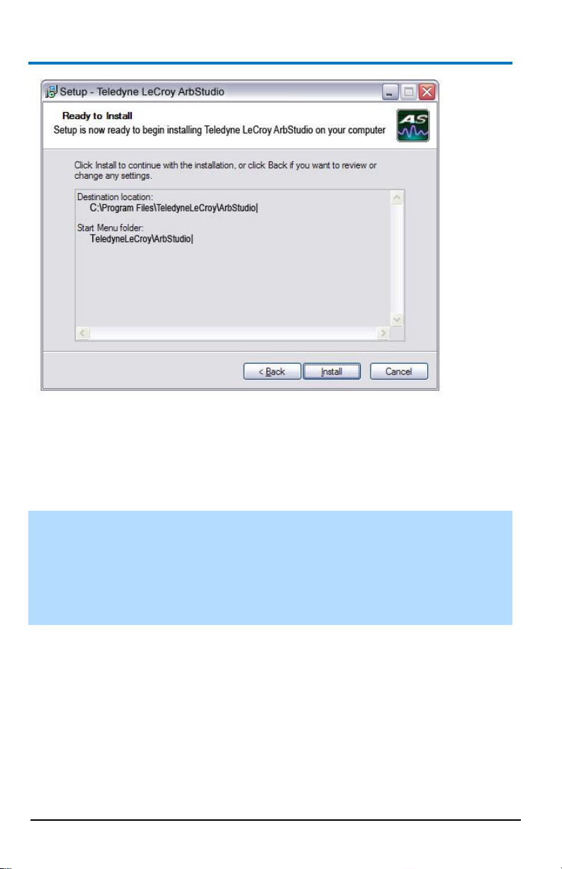
Review the installation summary shown on the Ready to Install screen and
click Install when ready.
B
Page 22
ArbStudio
14
922244-00 Rev A
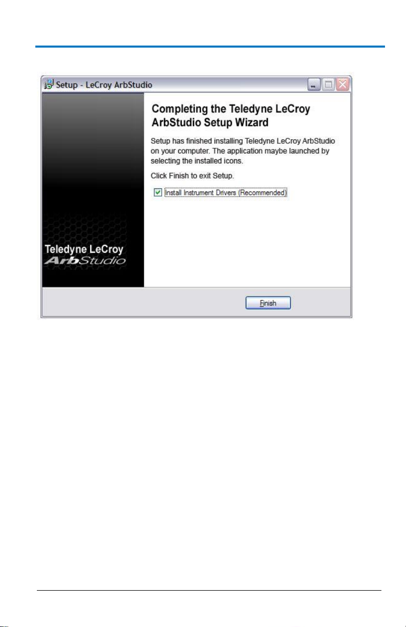
As the installation completes, the Completing the Teledyne LeCroy
ArbStudio Setup Wizard screen is shown as follows. This same screen also
provides a checkbox (marked by default) to continue the wizard and Install
Instrument Drivers. Leave the checkbox marked and proceed by clicking
the Finish button.
NOTE: While unmarking the checkbox and clicking the Finish button does
complete the software installation, it does not install the necessary system
drivers on your computer - making your ArbStudio system inoperable on
your computer. This is why it is strongly recommended to leave the Install
Instrument Drivers checkbox marked and proceed with the driver
installation.
Page 23
Operator’s Manual
922244-00 Rev A
15
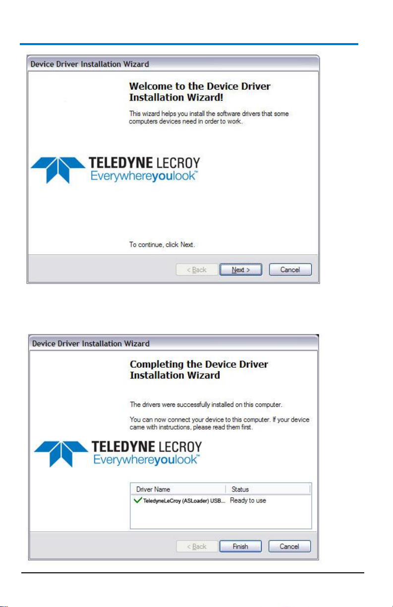
Driver Installation
Click Next to proceed past the Welcome to the Device Driver Installation
Wizard screen.
B
Page 24
ArbStudio
16
922244-00 Rev A
Select your device on the table shown in the Completing the Device Driver
Installation Wizard screen and click the Finish button.
Page 25
Operator’s Manual
922244-00 Rev A
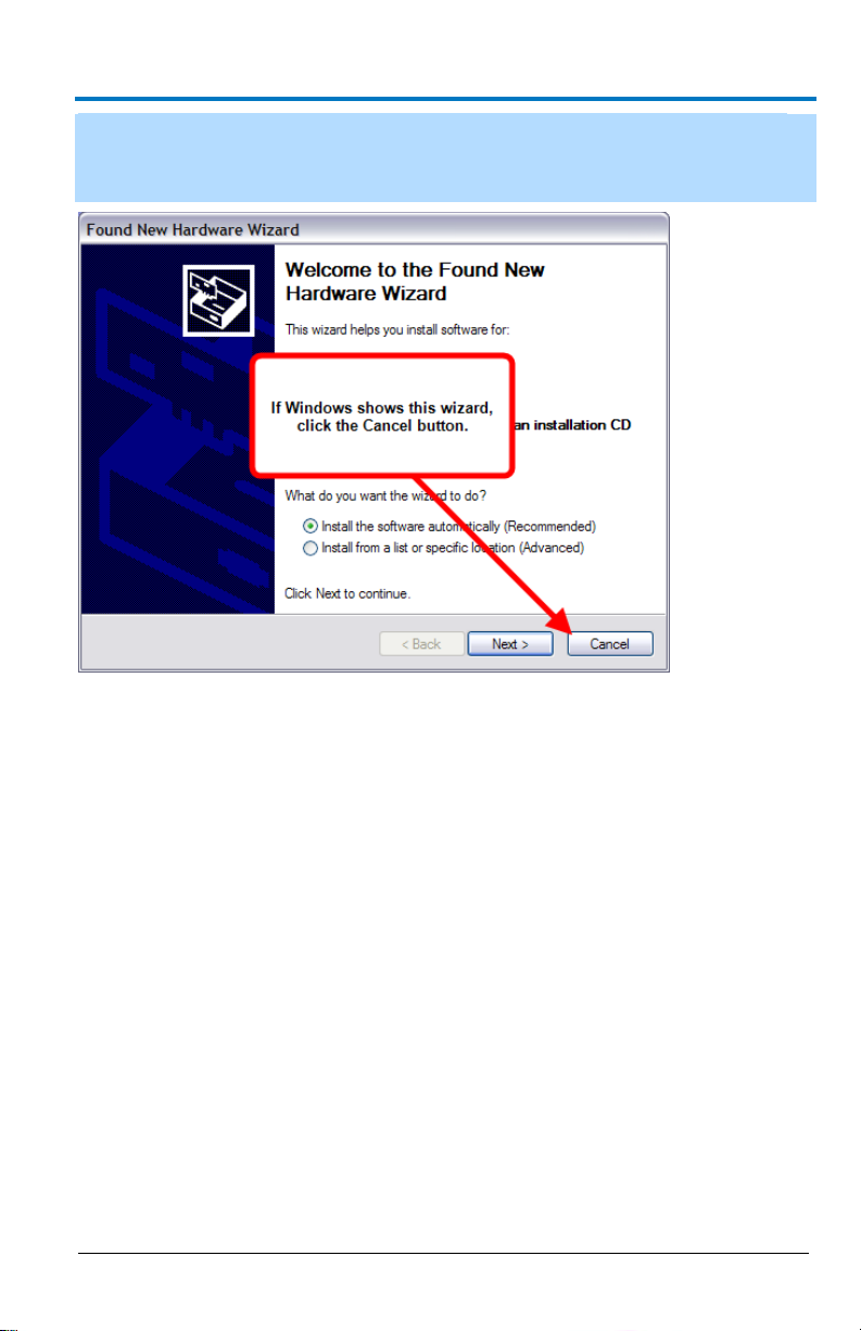
17
NOTE: If Windows shows the Found New Hardware Wizard, click Cancel.
Only use the ArbStudio Software and Driver installation procedure to
configure your system.
Now, with correct application software, drivers, and the latest .NET
Framework installed, your ArbStudio is ready for use.
Initial ArbStudio Software Interfaces
The ArbStudio software environment provides access to all product
functions. The interface allows you to control up to eight devices
connected by the Expansion Bus Cable configuring them as Arbitrary
Waveform Generators, Digital Pattern Generators, or Mixed Mode
Generators.
ArbStudio Workspace
The ArbStudio software workspace consists of two main elements:
The main document editing area, shown on the right side on the
The ArbStudio Control Navigation Tree, shown on the left side on
B
following screen-shot.
the following screen-shot.
Page 26
ArbStudio
18
922244-00 Rev A
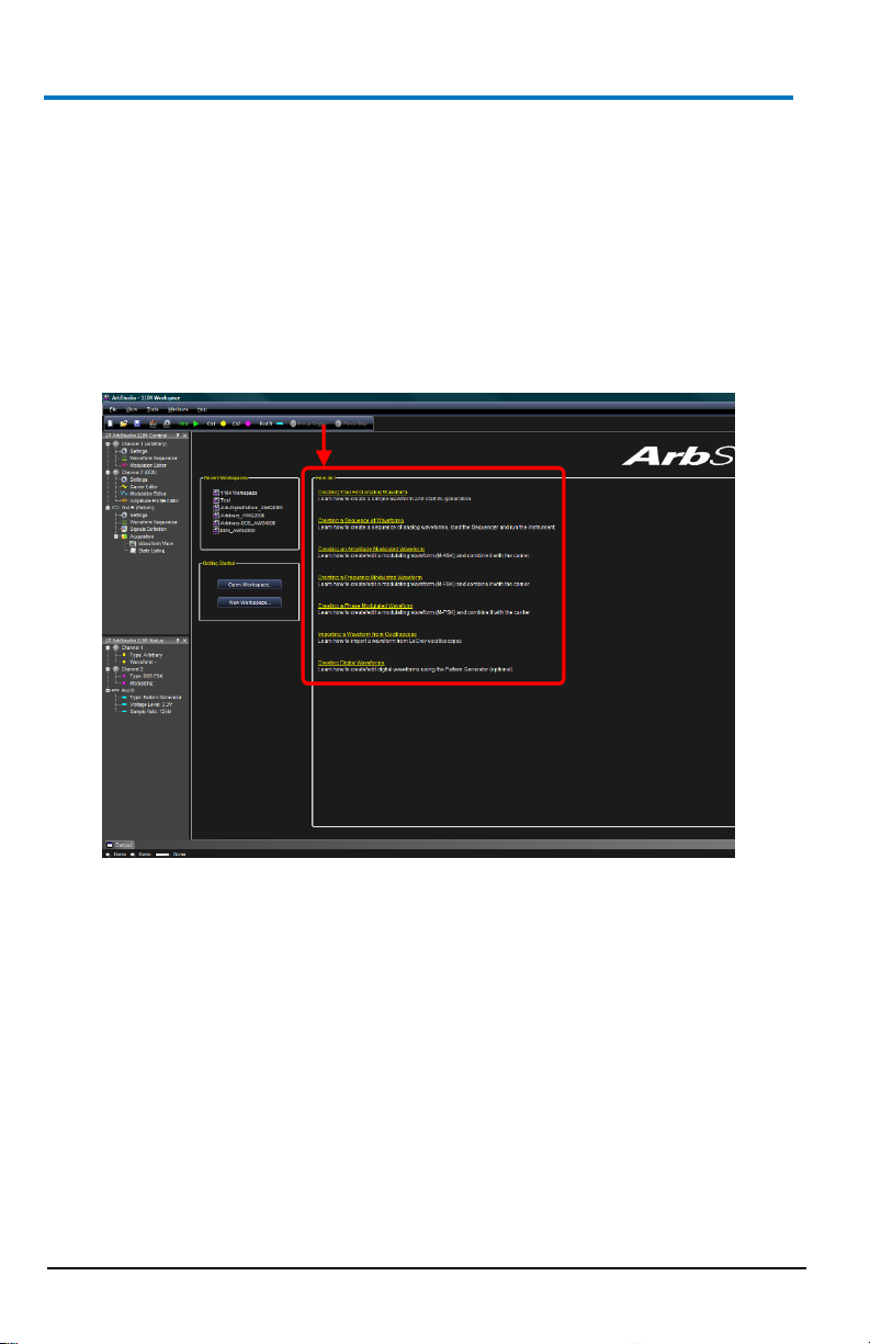
As mentioned, when you open the ArbStudio environment, the most
common initial tasks are displayed on the Welcome screen for easy
selection in a special view, called the How do I section.
The common tasks include the following:
"How do I" Scenario Details (on page 146)
Recent Workspaces
Open Workspace..
New Workspace..
Page 27
Operator’s Manual
922244-00 Rev A
19
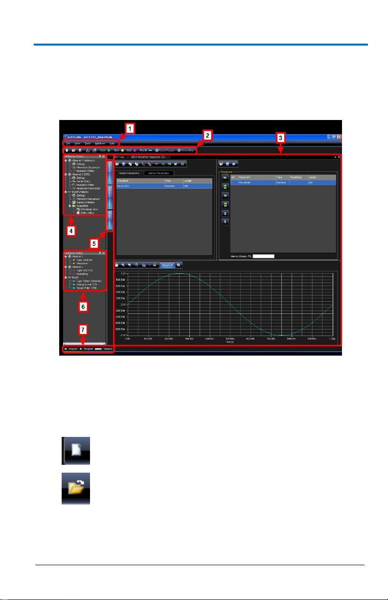
Interface and Display
The user interface is shown when you open an existing project or create a
new one. Numbered callouts on this image correspond with the following
interface section descriptions.
1. Menu Bar - Provides drop-down menu access to device functions,
2. Toolbar - Various functions including channel/pod selection, device
B
workspace, window management, and online help.
setup and instrument start/stop are made available as icons in this
area.
New Workspace - creates a new workspace.
Open Workspace - opens an existing workspace.
Page 28
ArbStudio
20
922244-00 Rev A
Ch(1, 2, 3, 4) - selects Channel - You can use this
available when the Digital Pattern option is enabled.
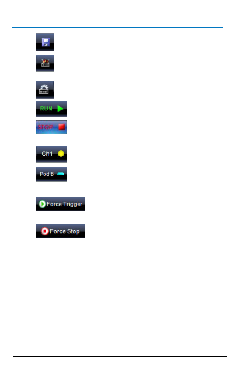
Save Workspace - saves newly-created or edited
workspaces.
System Setup - selects the Master/Slave channel when
multiple devices are connected by the expansion bus or
when you want channels managed by an event.
Device Setup - accesses more detailed ArbStudio option
settings.
RUN/STOP - first loads setting parameters and the
waveforms into the instrument, and then it
starts/stops the waveform generation for all enabled
channels selected from the Channels Selection
button.
Pod x - activates or deactivates the RUN/STOP
command for the specified Pod. This control is only
Force Trigger - makes the instrument generate
an internal trigger signal and forces a start
event on the selected channels/pods.
Force Stop - forces a stop event on the selected
channels/pods.
3. Editing Area - This main display area shows the waveforms selected
from the Project Waveform List or Sequencer Window. You can also
create/edit waveforms and load the Sequencer from this location.
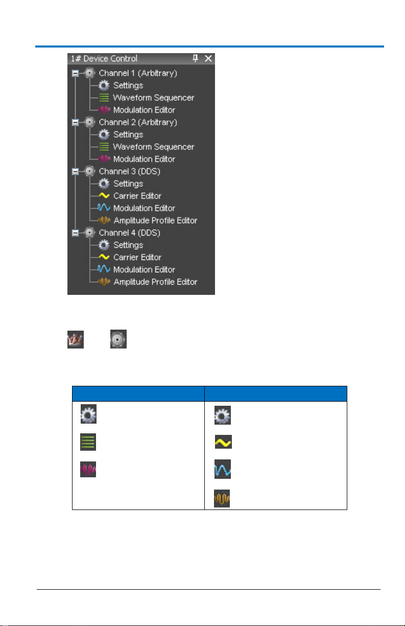
4. Device Control Tree - The Device Control (navigation) tree provides
access to channel settings and tools to edit standard/modulating
waveforms, set the amplitude profile of the modulated signal, and
load the sequencer.
Page 29
Operator’s Manual
922244-00 Rev A
21
Arbritrary
DDS
Settings
Settings
Waveform Sequencer
Carrier Editor
Modulation Editor
Modulation Editor
Amplitude Profile Editor
The icon associated to the channel string indicates if it is master or
slave, respectively.
The following icons are used based on Arbitrary or DDS mode
selection.
Settings - This tool allows setting the sampling rate prescaler,
B
the impedance output, the run mode (Single, Continuous,
Burst), and the external control signals (trigger IN, trigger
OUT).
Page 30
ArbStudio
22
922244-00 Rev A
Waveform Sequencer - This tool, available only in the
Arbitrary mode, allows you to edit the waveforms loaded in
the channel and to select generation order and number of
repetitions. The waveforms generated by this tool are
considered as carrier signals if the modulation is needed.
Modulation Editor - This tool allows editing a modulating
waveform. The signal edited can modulate the waveform
edited by the Waveform Editor tool, with a M-ASK, M-FSK or
M-PSK modulation law.
Amplitude Profile Editor - This tool, available only in DDS
mode, allows setting the amplitude profile of the modulated
signal as a function of the frequency.
Carrier Editor - This tool, available only in DDS mode, allows
editing the carrier waveform of the modulated signal.
5. Editing Area Tag - These tags conserve screen space by toggling the
display of your open waveforms.
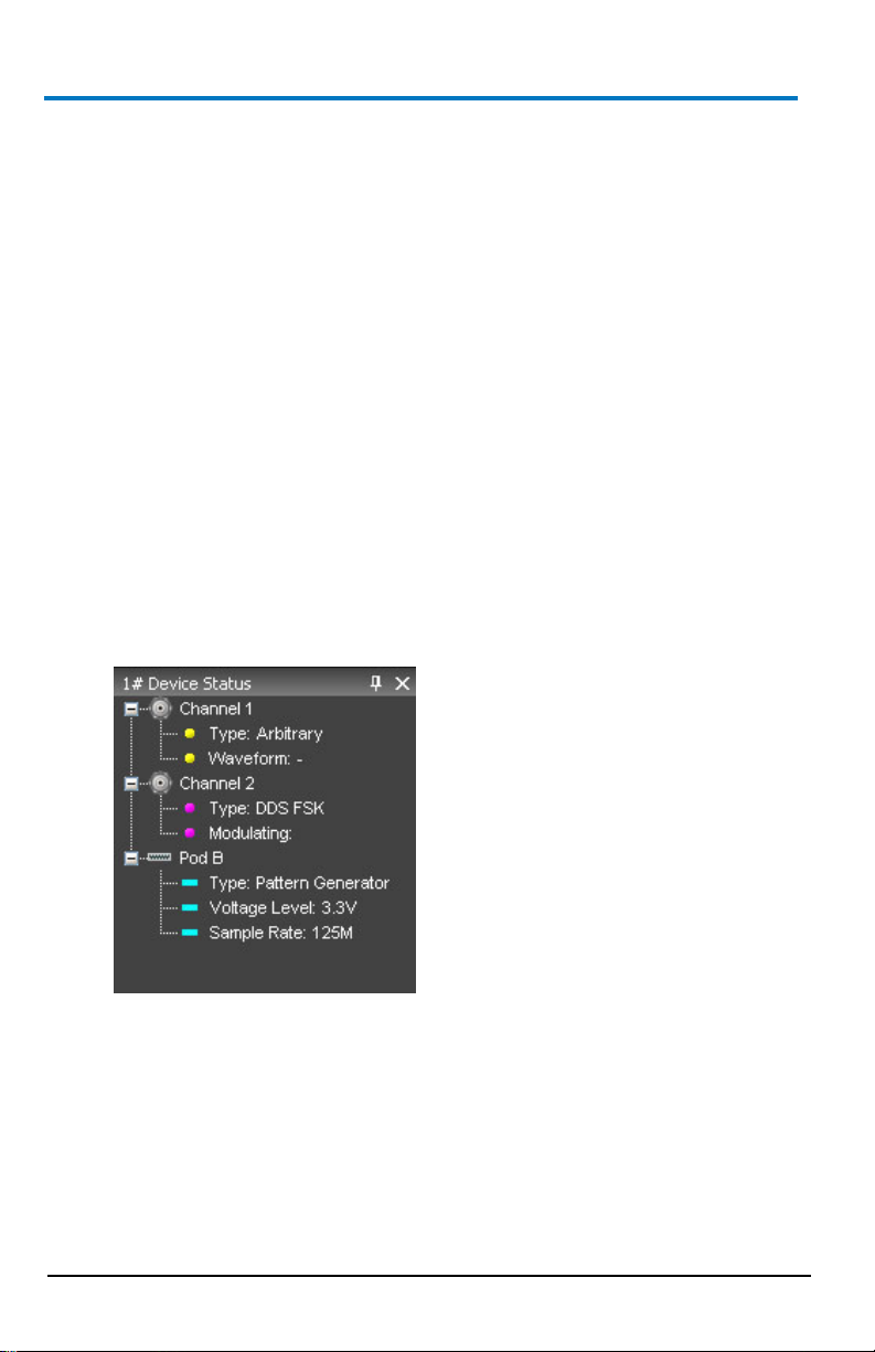
6. Device Status Tree - Lists various channel/pod instrument properties
such as sampling rate, channel type, and voltage level.
Type - Shows the channel functionality (Arbitrary, DDS, Digital
Pattern).
Waveform - In Arbitrary mode, it shows the current
waveform generated by the instrument.
Modulating - In DDS mode, it shows the phase or the
frequency of the modulating signal.
Voltage Level - Displays the Pod voltage level.
Sample Rate - The Sample rate of the Digital Pattern
Generator.
Page 31

Operator’s Manual
922244-00 Rev A
23
7. Status Bar - This are of the screen provides channel/pod run mode
status information as follows.
Initializing - The software is loading the firmware into the
instrument.
Ready - The instrument is ready to start.
Running - The ArbStudio hardware is running.
Stopped - The instrument is stopped.
Demo - The software is in demo mode.
PLEASE NOTE THE FOLLOWING:
When you press the Run/Stop button, the output log displays the
operation list the software is performing as it loads the waveforms
and settings into the instrument. If any operations cause an error or
a problem in the sequencer while loading, the log notifies you.
All of the panels are dockable; meaning they snap into convenient
screen positions adjacent to other panels. Move individual panels by
clicking the panel's top side, holding, and dragging with your mouse.
Setup Examples and Common Tasks
Overview
The following examples provide a quick way to learn standard ArbStudio
signal setups and common tasks:
1. Creating a New Workspace (on page 24)
2. Opening an Existing Workspace (on page 26)
3. Arbitrary Waveform Generator Setup Example (on page 27)
4. Digital Sampler Setup Example
In addition to the Setup Examples and Common Tasks, the end of this
manual also contains scenarios with detailed steps for performing typical
tasks and setups using ARBStudio as shown in the How do I section on the
Welcome screen (shown when first launching the software).
B
Page 32

ArbStudio
24
922244-00 Rev A
PLEASE NOTE THE FOLLOWING:
Before performing any of the scenarios, you must first make sure
you've correctly powered on your instrument, connected to your
PC, and launched the ArbStudio software as explained in the
Getting Started with ArbStudio (on page 10) section.
Some more specific steps are required around Creating a New
Workspace for each scenario. Details are provided for those
scenarios when necessary.
With the aforementioned prerequisites completed, you can perform the
following scenarios:
1. Creating Your First Analog Waveform (on page 147)
2. Creating a Sequence of Waveforms (on page 151)
3. Creating an Amplitude Modulated Waveform (on page 155)
4. Creating a Frequency Modulated Waveform (on page 161)
5. Creating a Phase Modulated Waveform (on page 166)
6. Importing a Waveform from an Oscilloscope (on page 171)
7. Creating Digital Waveforms (on page 175)
Creating a New Workspace
1. From the Start Page, click the New Workspace button.
The New Workspace form is shown and displays the connected
ArbStudio hardware on the Instrument selection section.
2. Enter a Name and Description for your new Workspace.
3. Click the Browse button to locate your workspace file, select it and
click the OK button.
The Setup Devices wizard is shown.
Page 33

922244-00 Rev A
25
4. Select your Operating Mode from:
Arbitrary Waveform Generator - Four arbitrary independent
channels are available and generate a wide range of complex
analog waveforms.
Pattern Generator - Available on 1102D and 1104D models.
Mixed Mode - Channel 1 and Channel 2 are available for
arbitrary analog waveform generation and Pod B is available
for 18 digital signals generation/acquisition.
Click Next.
PLEASE NOTE THE FOLLOWING:
Operator’s Manual
5. On the channel functionality configuration screen, make settings as
B
The ArbStudio 1104D has Arbitrary Waveform Generator,
Pattern Generator, and Mixed Mode operating modes.
The ArbStudio 1102D has Arbitrary Waveform Generator and
Pattern Generator operating modes.
desired for each channel to run in either:
Arbitrary Mode - If you need to generate a standard or
amplitude modulated waveform.
DDS Mode - If you need a frequency or phase modulated
signal.
Page 34

ArbStudio
26
922244-00 Rev A
6. Click Next. The wizard Finish screen is shown.
7. Click Finish.
NOTE: If your workspace contains additional ArbStudio devices, the
wizard does not show this Finish screen. Instead, the wizard repeats
itself to configure additional devices until all attached workspace
devices are setup properly.
When a workspace has been created or edited, the ArbStudio environment
becomes active and the workspace name is shown in the ArbStudio
window header.
Opening an Existing Workspace
1. Click the Open Workspace toolbar button.
The Open Workspace screen appears, displaying the AWGProjects
folder.
2. Select the desired workspace and click Open.
NOTE: Every workspace is associated with the serial number of a
connected ArbStudio instrument.
3. If a Serial ID for a previously connected ArbStudio instrument in your
workspace is different from ones currently connected, the Relink
Project Devices screen is shown:
Make new assignments using the Connected Device drop-down and
click OK.
Page 35

Operator’s Manual
922244-00 Rev A
27
Arbitrary Waveform Generator Setup Example
1. Power on the instrument and connected it to the PC.
2. Launch the software and click the Create Workspace button.
3. On the Setup Devices wizard, select Arbitrary Waveform Generator
as the operating mode and click Next.
4. Configure channel functionality as Arbitrary and click Next.
5. Click Finish.
B
The end of the wizard is shown.
Page 36

ArbStudio
28
922244-00 Rev A
6. Now, on the Device Control Tree, double click the Waveform
Sequencer item under Channel 1.
7. Click the Add Standard Waveform button.
The Waveform Standard Editor form is shown.
8. Choose a sine waveform with the following specs:
1 MHz frequency
250 samples
1 Volt amplitude
9. Select the Waveform1 on the Project Waveform tab and click the
Add button to include the waveform to the sequencer.
Page 37

Operator’s Manual
922244-00 Rev A
29
10. On the Device Control Tree, double click the Settings item under
Channel 1.
11. On the General tab of the DEV1 Settings Ch 1 screen, select the
appropriate Output Impedance value for your impedance load.
Example: When connecting ArbStudio to an oscilloscope, a 50 Ohm
output impedance load is selected here and 50 Ohms is also selected
as the input impedance on the oscilloscope channel.
12. On the Run Mode tab, select Single for the Run Mode field value
B
and click the OK button.
Page 38

ArbStudio
30
922244-00 Rev A
13. Press the Run/Stop toolbar button.
NOTE: Once the instrument has started (next step), Single Run Mode
repeats Waveform1 until either the Run/Stop or Force Stop toolbar
buttons are clicked.
The software loads the settings and waveforms into the ArbStudio
hardware and then generates waveforms.
Waveform1 ports to the CH1 BNC output, which can be connected
to an oscilloscope for signal analysis.
Digital Sampler Setup Example
1. Connect an ArbStudio with digital pattern generator capability to
your PC and open the ArbStudio software.
2. Click the Create Workspace button and follow the steps to
create a new workspace.
3. Connect the POD probe to Digital POD A.
4. On the Setup wizard, choose Pattern Generator mode.
5. Under POD A, select Signals Definition.
6. Enter CLK in the Bus or Signal Name field and press to add it to
the list of signals.
7. Select Ch0 from the list of channels on the right and press to
associate Ch0 with the CLK signal.
8. Repeat steps 6 and 7 to add the WR and RD signals, associating
them with Ch1 and Ch2, respectively.
9. Enter Data in the Bus or Signal Name field and associate it with as
many digital channels as required by the digital data. More than one
channel can be associated with the Data field by selecting all the
required channels and pressing the button.
10. Double-touch on the Waveform Sequencer of POD A under the
Control Navigation Tree.
Page 39

Operator’s Manual
922244-00 Rev A
31
11. Press to add a digital waveform to the Waveform List:
When the New Waveform window appears, press to add all
buses/signals to the digital waveform.
Enter either the time length or the number of samples under
Waveform Length.
Press OK to add the waveform to the Waveform List.
12. Press or double-click on Waveform1 to open the Editing
Waveform window.
13. Set WR, RD, and WriteRAM signals to 1 by selecting the “to 1”
button.
14. Expand the Data field and change CLK signal to HiZ. This changes the
pin direction from output to input. Press OK.
15. Select Waveform1 from the Waveform List and press to add it
to the sequencer.
16. Connect the digital leads from POD A to the digital signals, being
17. Press and allow ArbStudio to run long enough to capture
18. View the acquired data by selecting Waveform View under the
B
sure to connect each channel to the same channel it was associated
with in the ArbStudio software.
the applied digital data. Press to stop the acquisition.
Acquisition folder of POD A, then selecting to add the data to
the signal selection.
Page 40

ArbStudio
32
922244-00 Rev A
Channel Settings
Overview
Use Settings to control the channel settings of the instrument. Access
Settings by double clicking on the desired Channel in the Device Control
Tree.
The Settings screen is divided into the following tabs:
1. The General Tab (on page 33)
2. The Run Mode Tab (Waveform Sequence) (on page 35)
3. The Run Mode Tab (Modulation) (on page 39)
4. The Trigger IN Tab (on page 40)
5. The Trigger OUT Tab (on page 42)
Page 41

Operator’s Manual
922244-00 Rev A
33
Channel Settings - The General Tab
The General tab is shown by default when the Channel Settings screen is
opened.
Sections of the Channel Settings General tab are explained as follows:
Output Impedance
It allows setting the channel output impedance and it can be set at: 50
Ohm, Low or High Impedance.
Trigger Delay
You can set a delay from the trigger event (start) for each analog output
channel.
Amplitude Correction Factor
The Amplitude Correction Factor (CF) consider the deviation of the load
and of the channel source resistance from the nominal 50 Ohm resistance.
Follow the next steps to evaluate the CF:
Apply to the load a fixed 5 V nominal voltage using the strobe
B
functionality of the selected channel
Page 42

ArbStudio
34
922244-00 Rev A
Read the voltage load on the multimeter
CF = Voltage Read at the load / Nominal voltage at the load. For
example if the value read is 4.9 V, CF=4.9 V/5 V = 0.98
Sampling Settings
This section of the General Tab allows for dividing sampling Base Frequency
(see Setup Sampling Rate Section) for both the signal carrier and for a
possible M-ASK modulating signal, respectively.
CARRIER WAVEFORM
Sampling Rate Prescaler (SRP) may assume values ranging from 1
(maximum frequency) up to 16777216 (minimum frequency), by
multiples of 2.
The optimal selection of SRP must take into account both the
maximum frequency of the signal to be generated and its duration.
The limit on the maximum frequency comes from the Nyquist
sampling theory which imposes a frequency generation at least two
times the maximum frequency of the signals generated.
For example, if a sinusoid must be generated at 10 MHz, its sample
frequency generation must be at least 20 Msps. In that case,
however, the sinusoid period is represented by only 2 points.
ArbStudio has a set signal duration limit for the memory depth used while
saving waveform samples. In fact, the memory space allocated to the
sample storage makes the waveform duration inversely proportional to the
generation frequency.
In particular, the maximum duration of a waveform is given by the number
of possible samples divided by the generation frequency.
For example, a maximum frequency of 250 Msps and a memory depth of
2,097,152 samples, done by setting SRP = 1 (sampling rate = 250 Msps), can
have saved waveforms with a total length of 8.388608 ms and a time
resolution of 4 ns.
However, by setting SRP = 20 (sampling rate = 12.5 Msps), the total
waveform length becomes 167.77216 ms with a time resolution of 80 ns.
MODULATING WAVEFORM
When M-ASK modulation is used you can set Mod Sampling Rate Prescaler
(MSRP) for the modulating signal independent of the carrier signal.
Page 43

Operator’s Manual
922244-00 Rev A
35
MSRP may assume values ranging from 1 (maximum frequency) up
to 65532 (minimum frequency), by multiples of 4.
The optimal selection of MSRP must take into account both the
maximum frequency of the signal to be generated and its duration.
For example, an ArbStudio 1102/1104 with a maximum frequency of
125 Msps (on the modulating signal) and a buffer depth of 2,096,896
samples in static mode, done by setting SRP = 1 (sampling rate = 125
Msps), you can save a modulating waveform with total length of
16.775168 ms and a time resolution of 8 ns.
Channel Settings - The Run Mode Tab
(Waveform Sequence)
Use the Run Mode tab to define the generation mode for the edited
sequence and set the trigger for the modulating signal.
The Waveform Sequence Run Mode tab allows defining the generation
mode for the edited sequence in Arbitrary mode. The available drop down
Force Trigger options include Single, Continuous, Stepped, and Burst
explained as follows:
B
Page 44

ArbStudio
36
922244-00 Rev A
Single
When a Force Trigger command is applied, waveforms inserted in the
Generation Sequence are generated one after the other.
The last waveform is repeated until a Force Stop command is
received.
The sequence can be interrupted at any time by a Force Stop
command.
Continuous
When a Force Trigger command is applied, waveforms inserted in the
Generation Sequence are generated one after the other in a continuous
mode.
Page 45

Operator’s Manual
922244-00 Rev A
37
After the generation of the last waveform, ArbStudio starts again
with the first waveform, and then continues.
The sequence can be interrupted at any time by a Force Stop
command.
Stepped
A Force Trigger command activates the generation of the first waveform
present in the generation sequence.
This waveform is repeated for a number of times indicated in the repetition
number.
The instrument output maintains the value imposed by the last
A new Force Trigger command activates the generation of
After the generation of the last waveform, a new Force Trigger
The generation can be interrupted at any time by a Force Stop
Burst
In this mode the first Force Trigger command activates the first waveform
present in the Generation sequence.
B
sample of the generated waveform.
subsequent waveforms.
command activates again the generation of the first waveform.
command.
Page 46

ArbStudio
38
922244-00 Rev A
This waveform is generated in a continuous mode until a new Force Trigger
command is applied.
This Force Trigger command activates the generation of subsequent
waveforms (the generation of the latter waveform starts only when
all points of the previous one are generated).
A Force Trigger command applied during the generation of the last
waveform activates the generation of the first waveform.
The generation can be interrupted at any time by a Force Stop
command.
In this mode the repetition number associated to any waveform is
ignored (the generation of one waveform starts only when all points
of the previous one have been generated).
PLEASE NOTE THE FOLLOWING:
If a unique waveform is inserted in the Generation Sequence, the
Single, Continuous and Burst modes are equivalent.
The Stop command resets the generation sequence and sets the
output voltage at 0V. A Start command applied after a Stop
command activates always the generation of the first waveform in
the Generation Sequence.
In Burst mode the graph and the duration column of the modulation
table are disabled, having no meanings.
Page 47

Operator’s Manual
922244-00 Rev A
39
Channel Settings - Run Mode Tab (Modulation)
The Modulation Mode menu allows setting the trigger for the modulating
signal. Available options include Single, Continuous, and Burst.
Single
ARBITRARY
When the Force Trigger command is given, the carrier signal, see
Advanced Waveform Editing (on page 61), is modulated with the
edited, modulating signal samples.
The last sample of the modulating signal is applied to the signal
carrier until a Force Stop command is applied.
DDS
When a Force Trigger command is applied, the frequencies (or
phases) inserted in the Modulation Editor are generated one after
the other for a time interval specified on the Durations field.
The last frequency (or phase) is repeated until a Force Stop
command is received.
The sequence can be interrupted at any time by a Force Stop
command.
Continuous
ARBITRARY
When the Force Trigger command is given, the carrier signal, see
Once the last sample of the modulating signal is reached, ArbStudio
DDS
When a Force Trigger command is applied, the frequencies (or
After the generation of the last frequency (or phase), ArbStudio
The sequence can be interrupted at any time by a Force Stop
B
Advanced Waveform Editing (on page 61), is modulated with the
edited modulating signal samples.
returns to the first modulating signal sample until a Stop command
is applied.
phases) inserted in the Modulation Editor are generated one after
the other in a continuous mode.
returns to the first frequency (or phase).
command.
Page 48

ArbStudio
40
922244-00 Rev A
Burst (DDS Only)
After a Force Trigger command is received, the frequency (or phase)
defined in the Modulation Editor buffer is generated until another
Force Trigger is received.
At the next Force Trigger, the period of the waveform is completed
with the previous frequency (or phase) entry before the second
stage frequency (or phase) is generated.
Once the last frequency (or phase) is exhausted, the waveform's
frequency (or phase) resumes using the first value entry in the
Modulation Editor list.
The generation can be interrupted at any time by a Force Stop
command.
The Duration Time associated to any frequency (or phase) is ignored
when using Burst/DDS mode.
Channel Settings - The Trigger IN Tab
This section allows setting the Trigger In parameters.
Page 49

Operator’s Manual
922244-00 Rev A
41
Source Connector
Use this field to select the physical source for a Trigger In event. Choose
one of the following as explained.
BNC Trigger IN - The trigger event is received by the dedicated BNC
Connector on the instrument front panel.
Pod A Trigger IN - The trigger event is received by a dedicated Digital
input of the probe connected to the Pod A in the instrument front
panel - see Probe Description.
NOTE: Trigger IN source setting is mutually exclusive.
Edge
You can set the sensitive edge for the input trigger as Rising or Falling
Edges.
Action
You can set the action for ArbStudio to perform when there is an input
Trigger event. The possible options include:
A Start command being generated at any event.
A Stop command being generated at any event.
B
Page 50

ArbStudio
42
922244-00 Rev A
Channel Settings - Trigger OUT Tab
This section allows setting the Trigger OUT parameters.
Trigger out source
Allows selecting the possible trigger source which generates a Trigger Out
event.
One or more sources can be chosen at the same time.
The signals that can be sent to the Trigger OUT output include Start, Stop,
and Event.
NOTE: Pod A Trigger IN and BNC Trigger IN are available on even channels
only.
POLARITY
You can choose the Trigger OUT signal polarity as Positive or Negative.
DESTINATION
A logic combination of the Trigger Out event of the enabled channels is
always available on the dedicated BNC Connector and on Pod A / Pod B
Trigger Out signal on the instrument front panel see Setup Device Trigger
Out Math section.
Page 51

Operator’s Manual
922244-00 Rev A
43
Setup System
Access the Setup System screen by clicking the Setup System toolbar
button.
Setup System can be used when multiple devices are connected by the
expansion bus or when channels have to be managed by an event.
The Setup System screen is shown.
Now, from the Devices list on the left, select the Channel or Pod you
B
want to set as the Master, and then click the Set Channel as Master
button.
When the Master generates an event (Start, Stop, Marker) , now it
can be evaluated by the slave devices.
Page 52

ArbStudio
44
922244-00 Rev A
Slave devices can Start or Stop On the Master Event. Select the
Master Channel Event from the right list and associate it with Start
or Stop On of the selected slave. If you select None, the Master
Channel events are ignored.
Now the Start or Stop events on slave channels are synchronized
with Start, Stop, or Marker event on the Master channel.
Other buttons on the Setup System screen include:
Reinitialize to Default - Click this button and all devices are set as
the slave.
Set Slave Start on Master Start - Sets all slave devices to Start On
the Master Channel Start Event.
Set Slave Stop on Master Start - Sets all slave devices to Stop On the
Master Channel Stop Event.
Page 53

Operator’s Manual
922244-00 Rev A
45
Setup Device
Setup Device Overview
Use the Setup Device tabs to quickly access the following ArbStudio
parameters (the Timing tab is shown by default):
The Timing Tab (below)
The Channel Out Math Tab (on page 47)
The Trigger OUT Math Tab (on page 48)
The Digital I/O Tab (on page 49)
The Strobe Tab (on page 50)
Timing Tab
The sample rate for the pair of adjacent channels can be set to the
following ranges:
The 4S/s – 250 MS/s range for Arbitrary channels or Pattern
Generator Pods.
The 125 MS/s – 250 MS/s for DDS channels.
B
Page 54

ArbStudio
46
922244-00 Rev A
Interpolation Factor
One of 3 frequency interpolation types (1X, 2X or 4X) may be set for either
channel pairing.
The interpolated sample rate of each channel pair can be calculated as a
combination of the internal DAC's sample rate (250 MS/s for both
Arbitrary and DDS projects) and the frequency interpolation's factor.
The maximum interpolated sample rate is 1 GS/s and can be achieved by
selecting a 4X interpolation factor.
Clock Source
The clock source may be set to Internal or External.
If Internal is selected, the clock signal is generated internally.
If External is selected, the clock signal from the EXT CLOCK BNC
connector is used. When the External Clock is selected, an External
Clock Frequency must be set for your clock signal.
Multi Device Deskew Delay (1104 with Expansion Bus
option only)
This parameter can set a fine delay between multiple devices in order to
compensate the skew between the outputs belonging to different devices.
The skew delay is only active on Slave devices and can add a positive delay
respect to the Master.
When deskewing the channel delay of a slave device with respect to the
master, the Multi Device Deskew delay must be used in conjunction with
the trigger delay. Multi Device Deskew delay sets a fine delay and can only
be positive, while the trigger delay sets a normal delay and can also be
slightly negative.
The deskew delay is only effective when all devices work with the same
sampling frequency that must be in the following list: 250 MHz, 200 MHz,
150 MHz, 100 MHz, 75 MHz, 50 MHz, 37.5 MHz, 25 MHz.
Page 55

Operator’s Manual
922244-00 Rev A
47
Channel Out Math Tab
You can set a communication between adjacent channels allowing
computations to be performed between generated waveforms or between
a waveform and a constant.
Use the radio button to Enable operation on a channel pair.
Select the channel where the operation result is to be performed.
On the Multiplier, select the TX channel to multiply the TX waveform
On the Addend option select the TX channel or a constant value.
B
The selected channel is the Receiver (RX) and the other one is the
Transmitter (TX).
with the RX waveform or select a constant to multiply the RX
waveform with a fixed voltage.
Click the Add button to toggle the operator to subtraction instead.
Page 56

ArbStudio
48
922244-00 Rev A
Trigger OUT Math Tab
Enabled channels can have a logical combination set between all trigger
out events.
The possible operations include Force Low (force to low logic level signal),
Force High (force to high logic level signal), AND, OR, XOR, NAND, NOR,
and XNOR.
Results are made visible on the BNC Trigger OUT Connector and on the
Trigger Out signal of the digital connector (Pod A/B).
If the Pattern Generator option is available, click the Toggle button to
switch the BNC Trigger Out selection from the left pair to the right (or vice
versa).
Page 57

Operator’s Manual
922244-00 Rev A
49
Digital I/O Tab
Arbitrary/DDS Channels
You can generate a digital pattern for the analog waveforms of channel 1
and 3 (ArbStudio 1104 only).
Digital pattern generation can be used to test digital devices such as serial
and parallel DACs or to emulate protocols.
The 16-bit digital representation of the waveform samples is available on
the digital output connectors Pod A for channel 1 and Pod B for channel 3
(ARBStudio 1102D/1104D) as a digital pattern. The data is available after
some sample clock pipeline delay.
It is possible to set the output voltage level for digital pattern in the 1.6 V –
3.6 V range.
Pattern Generator
If the Pattern Generator option is enabled, you can set the output voltage
level for Pod A/B in the 1.6 V – 3.6 V range. The default value is set to 3.3 V.
NOTE: When the software is first loaded, the digital pattern generation is
disabled.
B
Page 58

ArbStudio
50
922244-00 Rev A
Strobe Tab
Channels Output Voltage (Arbitrary and DDS)
Use to set the DC Output voltage for the selected channel.
Pod A/B (Pattern Generator)
Use this panel to assign values to Digital Pattern Generator (optional) pins,
read their status, or set in a high impedance state. Use the following
explanations to guide your settings.
Strobe Vectors - Allows the assignment of values to Vectors[15..0],
to the Extended Trigger signal and to the Write RAM signal. By
pressing the Strobe button, the output pins change their logic levels
to the ones assigned.
Pods status - The Digital Pattern Generator can also operate as a
Sampler. Digital channels change their behavior from outputs to
inputs. When the Read Pods Status button is pressed, the logic level
of each input can be examined in real time.
HiZ Strobe - By pressing the Set HiZ button all digital channels will go
in a high impedance state.
Page 59

Operator’s Manual
922244-00 Rev A
51
The Waveform Sequencer - Analog
Creating Standard and Advanced Waveforms
Creating a Standard Waveform
Create a new waveform in the Waveform Sequencer using the following
steps.
Press the Add Standard Waveform button.
The Waveform Standard Editor dialog box is shown.
Provide a Name for your waveform.
Use the Type drop-down and select DC Level, Sine, Increase Ramp,
Use fields on the Timing section to set Length, Frequency, and Cycle
Fields on the Parameters section can be used to set Amplitude,
Click the OK button to create the waveform and add it to the
B
Sawtooth, Rectangle, or Triangle.
parameters.
Offset, Phase, Maximum and Minimum Voltage levels
project.
Page 60
ArbStudio
52
922244-00 Rev A
Creating an Advanced Waveform
Create a complex waveform in the Waveform Sequencer by clicking the
Add Advanced Waveform button.
Like Standard Waveform Creation, the Waveform Editor dialog box is again
shown.
ArbStudio handles Waveforms, Segments, and Components in the
following manner.
WAVEFORMS
Standard Waveform - A basic waveform like DC Level, Sine, Increase
Ramp, Triangle, Sawtooth, or Rectangle.
Advanced Waveform - A sequence of elementary waveforms, or
segments. A Waveform contains the temporal order by which the
segments are generated (and the number of repetitions for each
segment). A segment is a combination of components.
Page 61

Operator’s Manual
922244-00 Rev A
53
SEGMENT
A Segment contains one or more Components, all of the same length,
combined by means of the elementary Add, Subtract, Multiply, Divide
operations.
COMPONENT
A Component is the basic element for the construction of a Segment. Each
Component may be represented by a standard waveform (DC Level, Sine,
Cosine, Exponential, Triangle, Rectangle, Ramp, Pulse, Sync, Sawtooth,
Sweep), by a Formula, or its component samples can be loaded from a text
file.
In any case, the samples of a Component are calculated/loaded as a
function of the ArbStudio frequency (sample rate) and of the length of the
component itself (number of points).
THE WAVEFORM EDITOR / CARRIER EDITOR
Edit waveforms generated by ArbStudio using the Waveform Editor tool.
Depending on Arbitrary or DDS project type mode, edited waveforms
acquire different meanings.
Arbitrary - Edited waveforms can be generated as they have been
set. edited waveforms represent the signal carriers in case of
amplitude modulation.
DDS - Edited waveforms may only represent a period of the signal
carrier.
Think of a waveform as a list of segments, where each segment can be
positioned any way within the list and repeated as necessary. Consider the
following when selecting detailed analysis.
Each waveform may be constituted by an arbitrary number of
The maximum number of samples for all waveforms is fixed in
Each waveform must be constituted by an even number of samples
In Arbitrary mode an arbitrary number of waveforms can exist.
B
segments and each segment can be repeated an arbitrary number of
times.
Arbitrary Mode (2.097.152 samples 2M option). In DDS mode, the
maximum number is 2048 samples.
≥8. Each segment may have an even or an odd number of samples.
Unlike DDS mode, Arbitrary allows the number of edited waveforms
Page 62

ArbStudio
54
922244-00 Rev A
samples be lower than the maximum number set by the memory
installed in the instrument.
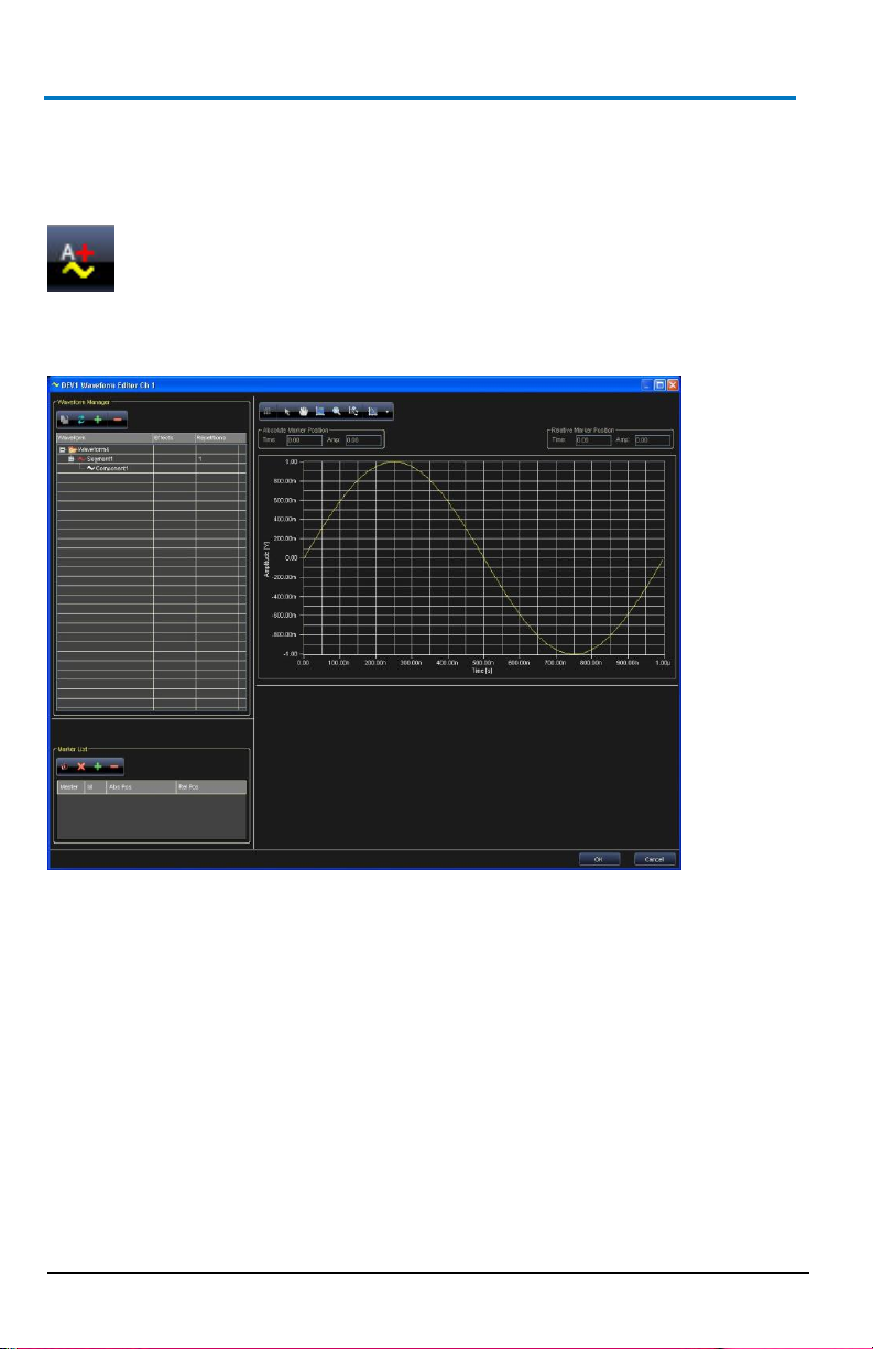
The Waveform Manager
The Waveform Manager is part of the Waveform Sequencer and provides
control of all possible waveform operations. Many common operations can
be directly performed on waveforms or are easily accessed from the
waveform tree (Selection, Drag and Drop, Right Click).
NOTE: Items selected on the waveform tree also updates some window
fields (on the right of the following screen-shot).
SELECTION
The window fields vary based on the selected item (Waveform or
Segment).
Waveform - When a waveform is selected, the graph is updated. The
information related to the selected waveform is shown.
Segment - Wen a segment is selected, the result of its components are
shown on the waveform graph.
The number of repetitions for each segment is shown in the Repetitions
column of the waveform tree.
Page 63

Operator’s Manual
922244-00 Rev A
55
DRAG AND DROP
A Drag and Drop operation on an item (Segment or Component) produces
its movement in another position within the tree. Some Drag and Drop
operations are not allowed and are automatically ignored (waveforms
within other waveforms).
RIGHT CLICK
A Right Click on a waveform tree item activates a pop-up menu, with
functions depending on a Waveform or Segment selection as follows.
Move Up and Move Down - Changes the position of the selected
object (Waveform or Segment) up/down in the list.
Add Segment or Component- If a waveform is selected, inserts a
new segment with its first component (Component1) in the last
position. If a component or segment is selected, inserts a new
component in the last position. Either way, the Edit Component
window is shown after segment/component creation.
Export Waveform... - With a waveform selected, this option saves
WAVEFORM EDITOR/MANAGER BUTTONS
When you have a waveform open in the editor, many of the Right Click
functions are also available directly from the Waveform Manager buttons
shown on the upper-left of the screen.
Export Waveform: Same as the right click option, exports the
Reinitialize Waveform - Reinitializes the waveform to the original
B
the waveform points to a flat text file.
waveform points to a flat text file.
condition, this command deletes all added segments and
components.
Page 64

ArbStudio
56
922244-00 Rev A
Add Segment/Component - Same as the right click option, if a
waveform is selected, inserts a new segment with its first
component (Component1) in the last position. If a component or
segment is selected, inserts a new component in the last position.
Either way, the Edit Component window is shown after
segment/component creation.
Delete - Removes a component or a segment from the Waveform
Manager.
Available Waveforms from the Waveform Display
Project Waveforms - This tab contains a list of all standard/advanced
waveforms previously created in your project. Right click on a selected
waveform and a pop-up is shown with the following options (many of these
functions are the same as the Waveform Editor/Manager buttons and the
right click, discussed previously):
Library Waveforms - Contains all waveforms (.wlf) stored in the selected
library folder.
NOTE: You can select a different library folder as your default in Tools →
Options. Change the location of the Waveforms Library Path.
Waveform Sequencer Buttons
The Sequencer buttons cover many functions as the Waveform
Editor/Manager buttons discussed previously. Many are also accessible via
right clicking a selection if preferred.
Load Waveform - Loads a waveform into the project waveform tab.
Page 65

Operator’s Manual
922244-00 Rev A
57
Save Waveform - Saves the selected waveform in Waveform Library
File (.wlf) format.
Import Waveform - Imports data from a selected flat text file (Tab or
Comma Separated, or .trc format) and converts it into a waveform
display.
Export Waveform - Exports the selected waveform to a flat text file.
B
Page 66

ArbStudio
58
922244-00 Rev A
Add Standard Waveform - Opens the Standard Waveform Editor
dialog box.
Add Advanced Waveform - Opens the Waveform Editor dialog box
for complex waveform editing.
Remove - Removes a component or a segment from the Project
Waveform tab.
Duplicate Waveform - Creates a new waveform just like the one
selected in the list.
Convert Waveform - Changes Standard waveform to Advanced.
Edit Waveform - Opens the selected waveform in the Waveform
Standard Editor dialog box.
Length Samples/Time
Page 67

Operator’s Manual
922244-00 Rev A
59
Waveform Graph Toolset
When viewing a waveform in the Waveform Editor, ArbStudio's main
toolset is provided and your waveform is plotted in a graph.
The toolset includes the following:
This button switches the X-axis representation between number of
This button allows changes the mouse function for the graphic area
The hand tool allows you to dragging inside the graph area.
B
samples to seconds. Default values are optimized based on the
selection made.
to cursors/markers movement.
Page 68

ArbStudio
60
922244-00 Rev A
This button resets all activated zooms.
This button allows zooming in on a selected rectangle of the graph.
Click and drag inside the graph area to create your zoom rectangle.
This button zooms in on an area of the graph along the X(Y)-axis.
Click and drag inside the graph area to create your zoom rectangle.
The scale on the Y(X)-axis does not change.
The right-side drop-down on this button provides the following plot
type options:
Point Style - Provides cross, plus, circle, etc. point styles for
the data points on the graph area.
Point Color - You can assign colors to data points as desired.
Line Style - You can set solid or dashed line styles for the
graph area.
Line Color - You can set colors for waveform lines as desired.
Line Width - You can set your waveform line width/thickness
as desired.
Anti-Aliased - Mark this checkbox and line plots appear
smoother. However, anti-aliased line drawings can be
computation intensive and slow performance.
Fill/Line to Base - Provides filling options (styles, colors,
width) for the waveform representation.
NOTE: First, click on a tool to select its function, and then click again
to show the On Screen Keyboard to provide specific value
data (where applicable).
Page 69

Operator’s Manual
922244-00 Rev A
61
Advanced Waveform Editing
This example edits a sine signal waveform (amplitude 5 V, frequency 10
kHz, duration 300 µs), concatenated to a triangular signal (amplitude 6 V,
frequency 20 kHz, duration 800 µs). The following steps demonstrate the
procedure.
1. Click the Add Advanced Waveform button to open the Waveform
2. Select Component1 of Segment1, choose sine wave in the
B
Editor dialog box.
component type, set its length to 300 µs, and 3 cycles in the
Parameters window. Now, set the amplitude to 5 V.
Page 70

ArbStudio
62
922244-00 Rev A
3. Now, in the Waveform Manager area, right click on Waveform1 and
select Add Segment.
4. Repeat the settings in step 2, only for Type select Triangle,
Frequency 20 kHz, Time 800 µs, and an Amplitude of 6 V.
5. Click Waveform1. The desired waveform is shown in the Waveform
Editor window.
Page 71

Operator’s Manual
922244-00 Rev A
63
Segment Editing
Segments, the building blocks of waveforms, are composed by a specific
combination of components with the same length. Editing a segment
requires the following Component Definition settings:
Setting the segment length as either time duration or number of
Adding a component by right clicking on the corresponding
Setting the component function (Add, Multiply,…) with respect to
Set the component type (Sine, Cosine, Triangle,…).
Set the component characteristics (Amplitude, Frequency, Phase,…).
Component Operation Field
The component operation field provides mathematical operators for
applying to the current component and others present in a segment.
Operators include Add, Sub, Multiply, and Divide. The operation is
performed on each data point in a component and on each component in a
segment. This example edits a rectangular waveform (amplitude 5V,
B
samples.
segment.
the segment.
Page 72

ArbStudio
64
922244-00 Rev A
frequency 200 kHz, duration 100 µs) amplitude-modulated with a period of
sine signal. The following steps demonstrate the procedure.
1. Click the Add Advanced Waveform button to open the Waveform
Editor dialog box.
2. Select Component1 of Segment1, choose sine wave in the
component type, set its length to 100 µs, and 1 cycle in the
Parameters window. Now, set the amplitude to 5 V.
3. Now, in the Waveform Manager area, right click on Waveform1 and
select Add Segment.
4. Select Add on the Component Operation drop-down field.
5. Select Segment1 and then click the Add Segment/Component
button in the Waveform Manager to add a new component.
6. In the Type field, select Rectangle, Frequency 200 kHz (or select 20
cycles from the first two parameters drop-down fields), Time 100 µs,
amplitude to 1 V, and duty cycle to 50%.
7. Set the segment amplitude (1 V) and duty cycle (50%).
8. Now select Multiply on the Component Operation drop-down and
click the OK button.
9. Click Waveform1 and the desired waveform is shown in the
Waveform Editor window.
Page 73

Operator’s Manual
922244-00 Rev A
65
NOTE: The order of components shown on the list is of basic importance
for the calculation of points composing the segment. By selecting a
component within the list, both the graph and the waveform editing
section are updated with the information of the selected component.
B
Page 74

ArbStudio
66
922244-00 Rev A
Type
Available Parameters
DC Level
Offset [V]
Sine
Frequency[Hz/cycles], Amplitude[V], Phase[°], Offset[V]
Cosine
Frequency[Hz/cycles], Amplitude[V], Phase[°], Offset[V]
Triangle
Frequency[Hz/cycles], Amplitude[V], Phase[°], Offset[V]
Rectangle
Frequency[Hz/cycles], Amplitude[V], Phase[°], Offset[V],
Duty Cycle [%]
Saw tooth
Frequency[Hz/cycles], Amplitude[V], Phase[°], Offset[V]
Increase Ramp
Amplitude[V], Offset[V]
Decrease Ramp
Amplitude[V], Offset[V]
Pulse
Amplitude[V], Delay[s], Width[s], Offset[V]
Sinc
Amplitude[V], Offset[V], Peak Position[s], Lobe Width[s],
Exponential
Frequency[Hz/cycles], Vo[V], Vinf[V], Time Constant[s]
Sweep
Amplitude[V], Offset[V], Start Frequency[Hz], Stop
Frequency[Hz]
Formula
Calculator Window
From File
Explorer Window
Component Type
The Type menu allows selecting the component among a list of possible
signals or functions.
Depending on the selected Type, different parameter may be edited. The
different possibilities include the following:
The Formula type allows defining the component by means of a
mathematical expression.
The component is edited by using the Formula Editor window that can be
activated by clicking the Edit Formula button. The mathematical expression
can be a function of time or a function of samples by using the t or x
variables, respectively.
The software verifies, in run time, that the component to be edited does
not exceed the limits for the selected output and that the formula syntax is
correct. In case of error, an error indication is shown in the Error message
indicator.
Page 75

Operator’s Manual
922244-00 Rev A
67
The From File type allows importing the components points from a text file
(*.txt) where the component voltages are reported in sequence.
Segment Parameters
Select a segment in the Waveform Manager and its graphical
representation is shown on the waveform graph to the right. For each
segment of the Waveform you can change the:
Segment Name
Repetitions - The number of times the segment is repeated inside
Waveform Parameters
Select the Waveform in the Waveform Manager. The tabs under the
waveform graph provide access to the Waveform Settings, Filter, and
Noise.
B
the waveform.
Page 76

ArbStudio
68
922244-00 Rev A
Settings
Waveform Name
Effects - For each waveform you can select to add a noise effect, a
filter, noise then filter (noise and filter), filter then noise (filter and
noise) .
Filter Settings
This operation allows applying a digital filter to the selected waveform. The
presence of a digital filter is evidenced by the Filter label in the Effects
column of the waveform tree.
The Filter setting window is divided into Application Zone, Specification,
and Parameters sections.
Page 77

Operator’s Manual
922244-00 Rev A
69
FILTER APPLICATION ZONE
This section allows selecting whether the digital filtering is to be applied to
the entire waveform or to a limited part. This option can be selected by
means of the Whole Waveform or Range option in the Application Zone
section, respectively.
In the Range case, two vertical lines appear in the graph area to delimit the
waveform section to be filtered. The two vertical lines can be moved by the
user. Their position is shown in the same Application Zone section.
Filter
This section allows setting all the characteristics of the filter.
FILTER SPECIFICATIONS
Digital Mode IIR (Infinite Impulse Filter) - Bessel, Butterworth,
Chebyshev, Inverse Chebyshev, and Elliptic.
Digital Mode FIR (Finite Impulse Filter) - EquiRipple, Kaiser, and
Windowed.
Type - Low Pass, High Pass, Band Pass, Band Stop, and General.
Type, Topology and filter Order options depend on the specific filter
characteristics.
Click the Confirm Data button and the set filtering options are applied to
the waveform.
A preview of the noise effects on the waveform is shown in the graph area.
You can remove a filter by clicking the current waveform and selecting the
None option on the Setting tab.
Noise
This operation allows applying a digital noise to the selected waveform.
The presence of a digital noise is evidenced by the Noise label in the Effects
column of the waveform tree.
The Noise setting window is divided into Application Zone, Noise
Specification, and Parameters sections.
NOISE APPLICATION ZONE
This section allows selecting whether the digital noise is to be applied to
the entire waveform or to a limited part of it. This option can be selected
B
Page 78

ArbStudio
70
922244-00 Rev A
by means of the Whole Waveform or Range option in the Application Zone
section, respectively.
In the Range case, two vertical lines appear in the graph area to delimit the
waveform section where the noise is to be applied. The two vertical lines
can be moved by the user. Their position is shown in the same Application
Zone section.
NOISE SPECIFICATIONS
This section allows setting all the noise characteristics.
Noise Type - Use this drop-down to select the noise type applied to the
waveform. Options include Gaussian, Uniform, and White. Depending on
the selected noise type, specific parameters (Standard Deviation or
Amplitude) are enabled together with the Scale Factor field, for
increasing/decreasing noise intensity.
Click the Confirm Data button and the noise options set are applied to the
waveform. A preview of the noise effects on the waveform is shown in the
graph area.
Remove a filter by clicking the current waveform and selecting None on the
Settings Tab.
Page 79

Operator’s Manual
922244-00 Rev A
71
Markers
The Markers List section of the Waveform Editor window allows setting one
or more markers for Arbitrary modes and only one marker in DDS mode.
ARBITRARY
In Arbitrary mode a marker identifies univocally a waveform sample.
A maximum of n markers can be inserted arbitrarily where n = number of
waveform's samples / 2.
During the waveform generation the marked samples generates a signal
pulse that may provoke a level change on the instrument Trigger Out, or
that may send a synchronous signal on a line of the Expansion Bus (if the
selected instrument is configured as Master - see Expansion Bus Section).
In general when you use a marker in Arbitrary mode, you can trigger others
channels or others instruments at a specified time while a waveform
generation is in progress.
The Add button puts a new cursor in the visualization area.
The Remove button eliminates the cursor selected in the Marker
screen.
Set Master Marker - The first marker added to the Marker screen is
Remove all cursors by clicking the Clear all markers button.
B
set as the Master with a zero relative position value on the graph.
Subsequent markers are created with positions relative to the
Master.
Change the master marker by selecting the new marker from the
Marker List and then clicking the Set Master Marker button.
Page 80

ArbStudio
72
922244-00 Rev A
The same marker operations are available by right clicking on one of the
markers in the list and selecting the desired function.
DDS (CARRIER EDITOR)
In DDS mode the only available marker identifies a single amplitude value
on the carrier waveform. During the waveform generation, when the
instrument output becomes higher than the marker value, a
leading/trailing edge on the Trigger Out signal is generated.
The Trigger Out signal remains high/low while the output signal remains
higher than the marker amplitude, at which point it switches.
The leading/trailing edge for the Trigger Out signal can be selected on the
Channel Settings Trigger Out tab.
If the selected instrument is configured as the Master, a marker can also
send a synchronous signal on an Expansion Bus line.
Page 81

Operator’s Manual
922244-00 Rev A
73
Sequencing Analog Waveforms
This section is for sequencing Analog waveforms. ArbStudio 1102D/1104D
include digital pattern generation capabilities. See, The Waveform
Sequencer - Digital Pattern (on page 110) for more information.
When using Arbitrary mode the Waveform Sequencer can be used to
Create Standard/Advanced waveforms, Add them in the project, or in the
Library and Load the sequencer. The Sequencer allows you to select which
edited waveforms are generated, their sequence, and number of
repetitions.
Editing a Sequence
The Sequencer allows you to select waveforms from the Project/Library list
for generation by the ArbStudio instrument. In the sequencer, you can also
choose the repetition and duration of waveforms.
Add/Remove waveforms to the Sequencer using the Sequencer Buttons.
Drag and Drop added waveforms to change their positions inside the
generation list.
B
Page 82

ArbStudio
74
922244-00 Rev A
PLEASE NOTE THE FOLLOWING:
All trigger modes (except the Burst trigger mode), any waveform
inserted in the generation sequence may be repeated an arbitrary
number of times (with an upper limit imposed by the hardware
capabilities of 8,589,934,592 number of repetitions).
Each waveform present in the Available Waveform section can be
inserted in the Generation Sequence an arbitrary number of times
and in any order.
Waveforms present in the Available Waveform list may not be
inserted in the Generation Sequence. These waveforms are loaded
in ArbStudio memory, but they are not generated.
The following commands are provide for sequence edit:
Load Sequencer - Loads a selected sequencer generation list.
Save - Saves the current sequencer generation list.
Edit - Edits the duration and repetitions of the selected waveform in
the sequencer generation list.
Add - Adds the selected Project waveforms to the Sequencer.
Add All - Adds all Project waveforms to the Sequencer.
Remove All - Removes all waveforms from the Sequencer
generation list.
Page 83

Operator’s Manual
922244-00 Rev A
75
Remove - Removes the selected waveform from the Sequencer
generation list.
Move Up - Moves the selected sequencer entry up in the list order.
Move Down - Moves selected sequencer entry down in the list
order.
Additional Waveform Sequencer Settings/Tools
Zoom
To move along the waveforms and to zoom, the Digital Editor window
provides many instruments (shown on the upper side toolbar) as follows:
The Selection Tool
The Hand Tool - Use the hand tool to pan the waveforms. Click and
Zoom In Auto - Click to zoom in.
Zoom Out Auto - Click to zoom out.
B
drag to move it.
Page 84

ArbStudio
76
922244-00 Rev A
Zoom Manual - Select this tool to manually select the area to zoom.
Click in the start point of the Waveform View and drag the cursor to
the end point keeping the left mouse button pressed.
Zoom All - Click to fit the visualization to view all the acquisition
time.
Waveform View Settings
You can change the properties of the graph display area. Click the
Waveform View Settings button and the Graph Property screen is shown.
Changes can be made as follows:
The Background Color can be changed as desired.
Change colors and turn the Major and Minor Grids on or off and
change their line coloring.
Cursor Position indicators can be turned on or off.
Page 85

Operator’s Manual
922244-00 Rev A
77
Signals Property Settings
Change signal properties by clicking the Signals Property button. The Signal
Property screen is shown.
Here you can change single signal colorings, the bus value display format,
transition modes, the space between, and the height of all signals.
NOTE: The minimum All Signals Height value is 20.
Cursors
Cursors (also called markers) are useful to identify and enlighten data for
improved organization and viewing. You can also use cursors to measure
and analyze acquired data.
Clicking the Markers button on the Digital Waveform Editor toolbar shows
or hides the marker window.
B
Page 86

ArbStudio
78
922244-00 Rev A
Other field values on the toolbar show the Active (or ID) of the currently
selected cursor, and its Absolute and Relative positions.
When Markers are turned on, all of the cursors present in the Digital Editor
are listed inside the Marker screen.
The Master Cursor is the one labeled with the following icon.
Relative positions are calculated from the master cursor position.
The master cursor automatically moved during a data search operation to
show relative results.
Change the master cursor by selecting the new cursor in the marker
window and clicking the Master Cursor icon in the Digital Editor toolbar.
NOTE: In the Digital Waveform Editor window, the master cursor is shown
in blue while the other cursors are shown in yellow.
Page 87

Operator’s Manual
922244-00 Rev A
79
Marker screen columns show the progressive cursor identifiers, the
absolute time position (the time distance between the cursor position and
the start of the acquisition) and the relative time position (the time
distance between the cursor and the master cursor). Any time one of the
cursors is moved, all the values are automatically updated and shown.
The following functions are used on Cursors
The Add button puts a new cursor in the visualization area.
The Remove button eliminates the cursor selected in the Marker
screen.
Move a cursor by clicking and dragging a selected cursor.
Remove all cursors by clicking the Clear all markers button.
PLEASE NOTE THE FOLLOWING:
You can also perform many of the aforementioned functions by right
You can remove all cursors except for one.
You can create as many cursors as needed.
Go To a Selected Target
The Go to field on the Digital Editor toolbar contains multiple functions on
its right side drop-down. The functions allow you to select the position
where the master cursor is going to be moved within the visualization area.
The Go to functions include:
B
clicking inside the Marker screen and choosing from the list of
functions shown.
Page 88

ArbStudio
80
922244-00 Rev A
Go to time - Moves the master cursor to the time position specified
in the text field to the left of the control.
Go to start samples - Moves the master cursor and visualization
area to the start of the acquisition.
Go to end samples - Moves the master cursor and visualization area
to the end of the acquisition.
Marker n - Centers the visualization area on the cursor/marker n
(position specified in the text field to the left of the control).
You can also move the selected cursor to the middle of the current
visualization by clicking the Move active cursor here button.
Search
Searching can be done from the Waveform Sequencer. It also is available in
the aforementioned search section regarding the State Listing and
Waveform View screens.
You can search for a specific bus, signal, rising, or falling edge value.
Activate the search option by clicking the Search Settings button.
The Search Settings window is shown and used to provide your search
criteria.
Page 89

Operator’s Manual
922244-00 Rev A
81
In the Signal Type search list on the right side of the Search Settings
window, all defined signals and busses are shown. Select the signal or bus
and then provide a specific value for the search.
NOTE: Depending on the Signal Type selected in the search list, the
Compare and Value fields contains different options.
Use the Compare field to select between the following search logic
operators:
= - Find the equivalent value.
!= - Find the unequal value.
> - Find values greater than the one specified (only available if a bus
< - Find values less than the one specified (only available if a bus is
HiZ - Find high impedance values.
Use the Value field to provide the specific value or edge on which to
search. If one Signal Type is selected, the Value field has the following
options:
0 - Searches for a logic 0.
1 - Searches for a logic 1.
HiZ - Search for a High Impedance (only for Pattern Generator
B
is selected).
selected).
Mode).
Page 90

ArbStudio
82
922244-00 Rev A
Rise - Searches for a Rising Edge trigger.
Fall - Searches for a Falling Edge trigger.
Change - Searches for any trigger edge.
The From Start button can be used to specify where the search starts
within your data acquisition. Possible options include:
From Start - Starts the search from the beginning of the acquisition.
From End - Starts the search from the end of the acquisition.
From Trigger - Starts the search from the trigger position.
Master Marker - Starts the search from the Master Marker position.
Select criteria on the Search Settings screen and click the OK button. The
results are then shown on the Waveform Sequencer.
Use the Search Backward or Search Forward buttons to navigate through
your search results.
NOTE: As you navigate through your search results, the master cursor is
updated to the subsequent values in your results.
Page 91

Operator’s Manual
922244-00 Rev A
83
Modulation Editor - Arbitrary/DDS
Overview
Use the Modulation Editor tool to create or edit a modulating waveform in
Arbitrary mode (M-ASK) and DDS mode (M-FSK and M-PSK).
The window contains the edit modulation section and the graph area.
Hardware Resources
ArbStudio allows you to save a limited number of modulating waveform
samples depending on hardware resources and the modulation type.
M-FSK / M-PSK modulations: maximum number of samples/Channel
M-ASK: maximum number of samples/Channel = 2047
ArbStudio allows a minimum and a maximum time resolution for the
modulating signal.
B
= 511
Page 92

ArbStudio
84
922244-00 Rev A
Maximum Resolution = 1/max sampling frequency (max sampling
frequency = 8 ns)
Minimum Resolution = Max Resolution * X (X = 4096 for M-ASK
and X = 1048576 for M-FSK and M-PSK)
Each sample of the modulating waveform may be separated respect
to the adjacent samples by a minimum of 8ns to a maximum of
32.768us for M-ASK and by a minimum of 8ns to a maximum of 8.38
ms for M-PSK and M-FSK.
A smart control of these intervals allows editing very long modulating
signals by generating the carrier at its maximum frequency.
Summarizing the previous statements, the maximum duration for the
modulating signal is 67.076ms for M-ASK modulation (MSRP = 1, Sampling
Rate in Setup Sampling Rate= 250 MHz) and 4.29s for M-PSK and M-FSK
modulations (Sampling Rate in Setup Sampling Rate= 250 MHz).
Edit Modulation Rule
This section provides information for setting the modulation type using the
Modulation type control (DDS mode only) and the modulating signal using
the Modulating Table and the Command Bar.
Modulation Type
This control allows setting the modulation type (Frequency or Phase) in
DDS mode, while in Arbitrary mode this option is not active since the only
available modulation type is the Amplitude one.
Amplitude (M-ASK) - In an Arbitrary mode channel the Modulation
Editor tool is automatically set to M-ASK. The window allows setting
the time behavior of the amplitude modulation factor. The samples
constituting the modulating signal may assume values between 0
and 1. These samples are the multiplying factors of the signal carrier
amplitude.
Frequency (M-FSK) - By selecting the frequency modulation, the
Modulation Editor tool is set to M-FSK. The window allows setting
the time behavior to be assumed by the carrier signal. The samples
of the modulating signal can assume values between 0 and 110 MHz.
Phase (M-PSK) - By selecting the phase modulation, the Modulation
Editor tool is set to M-PSK. The window allows setting the phase
shifts to be assumed by the carrier signal and the time instants at
Page 93

Operator’s Manual
922244-00 Rev A
85
which they occur. The carrier signal is generated at a frequency set
by the Base Frequency control (maximum 110 MHz for a ArbStudio
1102/1104 instrument), while samples of the modulating signal may
assume values between 0 and 360 degrees.
Modulating Table
Each row of the Modulating Table represents a time interval in which the
modulating signal may assume Constant values or Variable values
Constant Values - The modulating signal is kept at a constant value
for the entire interval duration. The corresponding row in the
Modulation Table is called an Entry.
Variable Values - The modulating signal varies within the time
interval, following a predefined behavior. The corresponding row in
the Modulation Table is called a Segment.
The first column contains the modulation coefficients or the Segment
names, while the second column contains the corresponding duration. The
time sequence of each table item can be modified by dragging an entry in
the desired position.
PLEASE NOTE THE FOLLOWING:
The Duration and Amplitude values inserted in the table are
The Memory Usage indicator visualizes in real time the occupation
Command Bar
The Command contains the following 6 buttons for editing the Modulation
Table.
Clear the Modulation Law
Delete the selected Entry or Segment on the Modulation Table
B
automatically rounded depending on the sampling rate and on the
instrument resolution.
of the hardware resources.
Page 94

ArbStudio
86
922244-00 Rev A
Add an Entry to the Modulation Table
Add a Segment to the Modulation Table
Export the modulation law to a flat, 2 column text file.
Import the modulation law from a flat, 2 column text file.
NOTE: In Single and Continuous Trigger mode, the graph representation of
the modulating signal is updated when any change is made to the
Modulation Table.
Modulation Entry Editor
The Modulation Entry Editor Tab is opened by clicking Add Entry button on
the Command Bar. This window allows setting the constant value for the
modulation coefficient (amplitude, frequency, phase) and its time duration.
Depending on its time duration, the Entry is represented by a number of
points optimizing the memory buffer occupancy (samples are separated at
the minimum resolution).
NOTE: A duration field values are ignored when using Burst mode.
Page 95

Operator’s Manual
922244-00 Rev A
87
Type
Parameters
Sine
Cycles, Amplitude*, Phase (°), Offset*
Cosine
Cycles, Amplitude*, Phase (°), Offset*
Triangle
Cycles, Amplitude*, Phase (°), Offset*
Rectangle
Cycles, Amplitude*, Phase (°), Offset*,
Duty Cycle (%)
Sawtooth
Cycles, Amplitude*, Phase (°), Offset*
Increase Ramp
Amplitude*, Offset*
Decrease Ramp
Amplitude*, Offset*
Modulation Segment Editor
Click the Add Segment button to open the Edit Modulation Segment
screen.
This screen allows you to edit a Segment - a time interval (Duration) in
which the samples of the modulation signal follow a predefined function
(Type).
The selectable functions and their available parameters include:
Table 3-1.Asterisk * indicates the parameter varies based on the modulation type
selected.
B
Page 96

ArbStudio
88
922244-00 Rev A
Two compression algorithms are used for a Segment memory usage
optimization. The algorithm used depends on the linear or non-linear
behavior of the selected function (Type).
The maximum compression factor corresponds to equally separated
samples in both cases, with a separation time equal to the minimum time
resolution allowed. Intermediate compression factors can be set by
controlling the amplitude factor (Decimation Factor).
Decimation Factor - Physically represents a percent value of the
signal maximum amplitude and is used by the compression
algorithm differently depending on the linear or nonlinear behavior
of the function selected (Type).
Linear Compression - The compression algorithm is linear for a
signal characterized by a linear time variation of the signal amplitude
(Increase Ramp, Decrease Ramp).
The compressed signal samples are equally spaced and the
separation between two successive samples is given by one of the
following conditions (the strictest one applies):
The maximum time separation between two successive
samples must be equal to the minimum resolution.
The minimum amplitude gap between two successive
samples is given by the percent of the maximum signal
amplitude, set by Decimation Factor. For example, a signal
with a maximum voltage of 10V and a Decimation Factor of
10%, the minimum voltage gap is 1 V.
Non-Linear Compression - The compression algorithm for non-linear
functions (Triangle, Rectangle, Sawtooth, Sine and Cosine) is similar
to the previous one, but the compressed signal samples are equally
separated only if the Decimation Factor is such that the former
condition is satisfied.
By using a suitable Decimation Factor the algorithm allows compressing the
modulating signal using a cluster of samples directly proportional to the
amplitude variation in the time unit.
Therefore, the compression algorithm for non-linear signals takes into
account the relative time variation of the signal amplitude.
Page 97

Operator’s Manual
922244-00 Rev A
89
If the Decimation Factor is very small with respect to the waveform
duration, the compression algorithm may not be able to perform the signal
compression by using the maximum number of available samples.
In such cases a message asks the user to increase the Decimation Factor.
Amplitude Profile Editor (DDS)
Overview
Use the Amplitude Profile tool to set the amplitude profile of the generated
signal as a function of its frequency.
For a given frequency of the modulated signal, its amplitude is
multiplied by the corresponding value of the amplitude profile
(whose samples vary between -1 and 1).
The amplitude profile is divided in three frequency intervals: Low
Frequency constant value, Intermediate Segment and High
Frequency constant value.
The window is divided in two main sections: the Limits settings
section and the visualization area.
B
Page 98

ArbStudio
90
922244-00 Rev A
Limits Settings
The frequency interval for the Intermediate Segment is described by
Frequency Inf [Hz] and Bandwidth [Hz].
The upper frequency for the Intermediate Segment is Frequency Inf
+ Bandwidth.
Frequency Inf must be set to a multiple of the Bandwidth value.
The 256 samples constituting the segment can be edited as a
standard segment, by editing its components.
The Profile Settings section is similar to the Segment Manager section
described in Advanced Waveform Editing (on page 61). With respect to the
Segment Manager case the component frequency can be provided only in
terms of Cycles, while the component amplitude must vary between -1 and
1.
The constant value amplitudes for the lateral interval are set by means of
the Amplitude Inf and Amplitude Sup indicators for the Low Frequency
constant value and the High Frequency constant value intervals,
respectively.
Profile Command
The following buttons are used for editing the Component List.
Add Component Adds a component to the list. This component can
be set for addition (or subtraction, multiplication, or division) with
others components in the list. An error message is shown when the
Component List exceeds the amplitude range.
Remove Component Removes a component from the Component
List.
Remove All Components Removes all components from the
Component List.
Page 99

Operator’s Manual
922244-00 Rev A
91
Digital Pattern Generator - Sampler
(Optional)
Overview
ArbStudio can be configured to work as a powerful Digital Pattern
Generator-Sampler.
In this working mode ArbStudio 1102/1104 provides the capability to
emulate standard serial or parallel bus transitions or custom digital
interfaces for system debugging and characterization.
The architecture is based on a vector/command memory and a powerful
sequencer defining the vector/command execution flow.
The Sequencer unit is a programmable finite state machine with a
microcode memory that, combined with the vector/command memory,
can generate very long digital patters and control signals at a very high
speed.
PLEASE NOTE THE FOLLOWING:
ArbStudio 1104D has 36 digital channels available, 18 CHs on Pod A
and 18 CHs on Pod B.
ArbStudio 1102D has only 18 digital channels on Pod A.
As a Digital Pattern Generator-Sampler ArbStudio provides:
36/18 Channels @ 125 MHz with Per Bit Direction (up to 288 Digital
2 Million Vectors in Generation
2 Million samples in Acquisition
Digital Waveform Sequencer
31 Levels Programmable Event Detector
2 Bank Programmable I/O Levels
Multi-device synchronization with Expansion Bus
Digital waveforms (vectors and commands) can be edited in a tabular
format or by means of a powerful and intuitive digital waveform editor that
provides tools for advanced pattern definitions: clock, count and random
patterns over a selection or the entire signal or bus.
B
I/O with Expansion Bus)
Page 100

ArbStudio
92
922244-00 Rev A
Pattern (Sampling and Acquisition) Settings
Pattern Settings
OVERVIEW
Use the Settings screen to configure correct pattern generation/acquisition
on your ArbStudio. The screen contains the following tabs.
1. Pattern Settings - The General Tab (on page 93)
2. Pattern Settings - The Trigger Event Tab (on page 94)
3. Pattern Settings - The Clock Generator Tab (on page 99)
4. Pattern Settings - The Trigger In Tab (on page 101)
5. Pattern Settings - The Trigger Out Tab (on page 102)
 Loading...