

Teledyne WORKHORSE Operation Manual
WORKHORSE
HORIZONTAL H-ADCP
OPERATION MANUAL
Information included herein is controlled by the Export Administration Regulations (EAR) and may
require an export license, license exception or other approval from the appropriate U.S.
Government agency before being exported from the United States or provided to any foreign
person. Diversion contrary to U.S. law is prohibited.
P/N 957-6212-00 (May 2015)
© 2015 Teledyne RD Instruments, Inc. All rights reserved.

Page ii
EAR-Controlled Technology Subject to Restrictions Contained on the Cover Page.

TABLE OF CONTENTS
CHAPTER 1 - AT A GLANCE ...................................................................................................................................1
How to Contact Teledyne RD Instruments ................................................................................................... 2
Conventions Used in this Manual................................................................................................................. 2
System Overview .......................................................................................................................................... 3
Inventory List ............................................................................................................................................... 5
Computer Considerations ............................................................................................................................ 6
Power Overview ........................................................................................................................................... 7
Setting up the H-ADCP System ..................................................................................................................... 8
Connecting to the H-ADCP ................................................................................................................... 9
Testing the H-ADCP .............................................................................................................................. 10
Changing the Baud Rate in the H-ADCPs .............................................................................................. 12
Caring for the H-ADCP System ..................................................................................................................... 13
General Handling Guidelines ................................................................................................................ 13
Assembly Guidelines ............................................................................................................................ 13
Deployment Guidelines ........................................................................................................................ 14
CHAPTER 2 - INSTALLATION ..................................................................................................................................15
I/O Cable and Dummy Plug .......................................................................................................................... 16
Routing Cables ............................................................................................................................................. 18
Cable Wiring Diagrams ................................................................................................................................. 19
Installation ................................................................................................................................................... 20
Cathodic Disbondment and Galvanic Corrosion ................................................................................... 21
H-ADCP Orientation ............................................................................................................................. 22
Attaching the H-ADCP to a Structure ................................................................................................... 23
H-ADCP Wave System Installation Checklist ........................................................................................ 25
Testing the Installed H-ADCP................................................................................................................ 27
Periodic Maintenance .................................................................................................................................. 29
CHAPTER 3 – COLLECTING DATA ............................................................................................................................31
Collecting Data with SurfaceView ................................................................................................................ 32
Data Playback with SurfaceView .................................................................................................................. 37
Data Recovery .............................................................................................................................................. 38
Recover a Single File using BBTalk ........................................................................................................ 38
Recover the Entire Recorder using BBTalk ........................................................................................... 38
Recover a Single File Using Direct Commands ..................................................................................... 39
Recover Recorder Using Direct Commands.......................................................................................... 40
CHAPTER 4 - MAINTENANCE .................................................................................................................................41
Parts Location Drawings ............................................................................................................................... 42
Maintenance Schedule ................................................................................................................................. 45
Calibration Items .................................................................................................................................. 45
Maintenance Items .............................................................................................................................. 45
Spare Parts ................................................................................................................................................... 47
Disassembly and Assembly Procedures ....................................................................................................... 49
Housing Assembly Removal ................................................................................................................. 49
End-Cap Removal Procedures .............................................................................................................. 50
H-ADCP Re-assembly ............................................................................................................................ 51
O-ring Inspection and Replacement ..................................................................................................... 51
Housing Assembly Replacement .......................................................................................................... 52
End-Cap Replacement .......................................................................................................................... 53
Periodic Maintenance Items ........................................................................................................................ 54
Replacing the Desiccant Bags ............................................................................................................... 54
Cleaning the Pressure Sensor Port ....................................................................................................... 55
Preventing Biofouling ........................................................................................................................... 55
Antifouling Paints ........................................................................................................................... 56
Page iii
EAR-Controlled Technology Subject to Restrictions Contained on the Cover Page.

Applying Antifouling Paints ............................................................................................................ 56
Removing Biofouling ...................................................................................................................... 58
Zinc Anode Inspection and Replacement ............................................................................................. 58
Zinc Anode Inspection .................................................................................................................... 58
Zinc Anode Electrical Continuity Check .......................................................................................... 59
Zinc Anode Replacement ............................................................................................................... 59
Calibrating the Compass....................................................................................................................... 60
Compass Background ..................................................................................................................... 60
Preparing for Calibration................................................................................................................ 61
Compass Calibration Verification ................................................................................................... 61
Compass Calibration ...................................................................................................................... 61
Installing Firmware Upgrades .............................................................................................................. 63
Installing Feature Upgrades ................................................................................................................. 64
Corrective Maintenance Items ..................................................................................................................... 65
Protective Coating Inspection and Repair ............................................................................................ 65
PC Card Recorder ................................................................................................................................. 66
Replacing Fuses .................................................................................................................................... 67
Changing Communications Setting ...................................................................................................... 67
Installing the Spare Boards Kit ............................................................................................................. 68
Remove the Original Set of Boards ................................................................................................ 69
Installing the Spare Board Kit ......................................................................................................... 70
Installing the Beam Cosine Matrix ................................................................................................. 71
Installing the Pressure Sensor Coefficients .................................................................................... 72
Testing the System after Board Replacement ................................................................................ 72
Replacing the End Cap Connector ........................................................................................................ 73
Equipment Provided ...................................................................................................................... 73
Customer Supplied Additional Equipment ..................................................................................... 73
Removing the End-Cap Connector ................................................................................................. 74
Installing the New End-Cap Connector .......................................................................................... 75
Wiring Diagrams ............................................................................................................................ 77
Replacing the H-ADCP Lithium Battery................................................................................................. 78
Testing the Lithium Battery Voltage .............................................................................................. 78
Replacing the Lithium Battery ........................................................................................................ 79
CHAPTER 5- TROUBLESHOOTING ............................................................................................................................81
Equipment Required .................................................................................................................................... 82
Basic Steps in Troubleshooting .................................................................................................................... 83
Troubleshooting the H-ADCP ....................................................................................................................... 83
Troubleshooting Safety ........................................................................................................................ 83
Troubleshooting a Communication Failure .................................................................................................. 84
Incorrect Wakeup Message ........................................................................................................... 84
No Wakeup Message ..................................................................................................................... 85
Check the Power .................................................................................................................................. 85
Check the I/O Cable .............................................................................................................................. 86
H-ADCP Checks ..................................................................................................................................... 86
Troubleshooting a Built-In Test Failure ........................................................................................................ 87
When to use the Spare Boards Kit........................................................................................................ 87
Troubleshooting a Beam Failure .................................................................................................................. 89
Troubleshooting a Sensor Failure ................................................................................................................. 90
Fault Log ............................................................................................................................................... 90
System Overview .......................................................................................................................................... 91
Operating Modes ................................................................................................................................. 91
Command Mode ............................................................................................................................ 91
Ping Mode ...................................................................................................................................... 91
Overview of Normal H-ADCP Operation............................................................................................... 92
Functional Description of Operation .................................................................................................... 92
Input Power ................................................................................................................................... 92
Board Descriptions ......................................................................................................................... 93
Page iv
EAR-Controlled Technology Subject to Restrictions Contained on the Cover Page.

Sensors ........................................................................................................................................... 94
CHAPTER 6 - RETURNING SYSTEMS TO TRDI FOR SERVICE ............................................................................................99
Shipping the H-ADCP .................................................................................................................................... 100
Returning Systems to the TRDI Factory ........................................................................................................ 101
Returning Systems to TRDI Europe Factory .................................................................................................. 102
CHAPTER 7 - SPECIFIC ATIONS ................................................................................................................................105
Outline Installation Drawings ....................................................................................................................... 108
CHAPTER 8 - COMMANDS ....................................................................................................................................115
Data Communication and Command Format .............................................................................................. 116
Command Input Processing ................................................................................................................. 116
Data Output Processing........................................................................................................................ 117
Using Direct Commands to Deploy .............................................................................................................. 118
Command Summary ..................................................................................................................................... 119
Command Descriptions ................................................................................................................................ 123
? – Help Menus .............................................................................................................................. 123
Break .............................................................................................................................................. 124
Expert Mode .................................................................................................................................. 125
OL - Features .................................................................................................................................. 125
Compass Commands .................................................................................................................................... 126
Available Compass Commands............................................................................................................. 126
Compass Command Descriptions ......................................................................................................... 126
AC – Output Active Calibration Data .............................................................................................. 126
AD – Display Factory or Active Calibration Data ............................................................................ 127
AF – Field Calibrate Compass ......................................................................................................... 128
AR – Return to Factory Calibration ................................................................................................ 128
AX – Examine Compass Calibration ................................................................................................ 129
AZ – Zero Pressure Sensor ............................................................................................................. 130
Bottom Track Commands ............................................................................................................................. 131
Available Bottom Track Commands ..................................................................................................... 131
Bottom Track Command Descriptions ................................................................................................. 131
BA - Evaluation Amplitude Minimum ............................................................................................. 131
BB – High Bandwidth Maximum Depth.......................................................................................... 132
BC - Correlation Magnitude Minimum ........................................................................................... 132
BE - Error Velocity Maximum ......................................................................................................... 132
BF - Depth Guess ............................................................................................................................ 133
BI - Gain Switch Depth ................................................................................................................... 133
BK – Water-Mass Layer Mode........................................................................................................ 134
BL - Water-Mass Layer Parameters ................................................................................................ 134
BM - Bottom Track Mode .............................................................................................................. 135
BP – Bottom-Track Pings per Ensemble ......................................................................................... 136
BR - Resolution ............................................................................................................................... 136
BS - Clear Distance Traveled .......................................................................................................... 137
BX – Maximum Tracking Depth ...................................................................................................... 137
BZ - Coherent Ambiguity Velocity .................................................................................................. 138
Control System Commands .......................................................................................................................... 139
Available Control System Commands .................................................................................................. 139
Control System Command Descriptions ............................................................................................... 139
CB - Serial Port Control .................................................................................................................. 139
CF - Flow Control ............................................................................................................................ 140
CG – Swap Beams 1 & 2 ................................................................................................................. 141
CK - Keep Parameters .................................................................................................................... 141
CL – Sleep Enable ........................................................................................................................... 141
CM - Master ................................................................................................................................... 142
CN - Save NVRAM to Recorder ....................................................................................................... 142
CP – Polled Mode ........................................................................................................................... 142
CQ – Transmit Power ..................................................................................................................... 143
Page v
EAR-Controlled Technology Subject to Restrictions Contained on the Cover Page.

CR – Retrieve Parameters .............................................................................................................. 144
CS – Start Pinging (Go) ................................................................................................................... 144
CY - Clear Error Status Word .......................................................................................................... 145
CZ – Power Down H-ADCP ............................................................................................................. 146
Environmental Commands ........................................................................................................................... 147
Available Environmental Commands ................................................................................................... 147
Environmental Command Descriptions ................................................................................................ 147
EA - Heading Alignment ................................................................................................................. 147
EB - Heading Bias ........................................................................................................................... 148
EC - Speed of Sound ....................................................................................................................... 148
ED - Depth of Transducer ............................................................................................................... 148
EH - Heading .................................................................................................................................. 149
EP - Pitch (Tilt 1) ............................................................................................................................. 149
ER - Roll (Tilt 2) ............................................................................................................................... 150
ES – Salinity .................................................................................................................................... 150
ET - Temperature ........................................................................................................................... 150
EX – Coordinate Transformation .................................................................................................... 151
EZ - Sensor Source .......................................................................................................................... 152
Fault Log Commands .................................................................................................................................... 153
Available Fault Log Commands ............................................................................................................ 153
Fault Log Command Descriptions ......................................................................................................... 153
FC – Clear Fault Log ........................................................................................................................ 153
FD – Display Fault Log .................................................................................................................... 153
Performance and Testing Commands .......................................................................................................... 154
Available Performance and Testing Commands ................................................................................... 154
Performance and Testing Command Descriptions ............................................................................... 154
PA – Pre-deployment Tests ............................................................................................................ 154
PC – User-Interactive Built-In Tests ................................................................................................ 155
PD - Data Stream Select ................................................................................................................. 156
PM - Distance Measurement Facility ............................................................................................. 157
PS – Display System Parameters .................................................................................................... 157
PT - Built-In Tests ........................................................................................................................... 159
PT Test Results Error Codes ........................................................................................................... 159
PT0 - Help ....................................................................................................................................... 159
PT2 - Ancillary System Data ........................................................................................................... 160
PT3 - Receive Path ......................................................................................................................... 160
PT4 - Transmit Path ........................................................................................................................ 161
PT5 - Electronics Wrap Around ...................................................................................................... 162
PT6 - Receive Bandwidth ............................................................................................................... 163
PT7 - RSSI Bandwidth ..................................................................................................................... 163
Recorder Commands .................................................................................................................................... 165
Available Recorder Commands ............................................................................................................ 165
RA - Number of Deployments ........................................................................................................ 165
RB - Recorder Built-In Test ............................................................................................................. 165
RE – Erase Recorder ....................................................................................................................... 166
RF – Recorder Free Space (Bytes) .................................................................................................. 166
RN – Set Deployment Name .......................................................................................................... 166
RR – Show Recorder File Directory ................................................................................................ 167
RS - Recorder Free Space (Megabytes) .......................................................................................... 167
RY – Upload Recorder Files ............................................................................................................ 167
Timing Commands ....................................................................................................................................... 168
Available Timing Commands ................................................................................................................ 168
Timing Command Descriptions ............................................................................................................ 168
TB - Time per Burst ........................................................................................................................ 168
TC - Ensemble per Burst ................................................................................................................. 169
TE – Time per Ensemble ................................................................................................................. 169
TF – Time of First Ping .................................................................................................................... 169
Page vi
EAR-Controlled Technology Subject to Restrictions Contained on the Cover Page.

TG – Time of First Ping (Y2k Compliant) ......................................................................................... 170
TP – Time Between Pings ............................................................................................................... 171
TS – Set Real-Time Clock ................................................................................................................ 171
TT – Set Real-Time Clock (Y2k Compliant)...................................................................................... 172
Water Profiling Commands .......................................................................................................................... 173
Standard Water Profiling Commands ................................................................................................... 173
WA - False Target Threshold Maximum ......................................................................................... 173
WB - Bandwidth Control ................................................................................................................ 174
WC - Low Correlation Threshold .................................................................................................... 174
WD – Data Out ............................................................................................................................... 175
WE - Error Velocity Threshold ........................................................................................................ 175
WF – Blank after Transmit ............................................................................................................. 176
WI - Clip Data Past Bottom ............................................................................................................ 176
WJ - Receiver Gain Select ............................................................................................................... 176
WL - Water Reference Layer .......................................................................................................... 177
WN – Number of Depth Cells ......................................................................................................... 177
WP – Pings Per Ensemble ............................................................................................................... 177
WQ - Sample Ambient Sound ........................................................................................................ 178
WS – Depth Cell Size ...................................................................................................................... 178
WT - Transmit Length ..................................................................................................................... 178
WU - Ping Weight ........................................................................................................................... 179
WV – Ambiguity Velocity ............................................................................................................... 179
WW – Mode 1 Pings before Mode 4 Re-Acquire ........................................................................... 180
WY – Mode 1 Bandwidth ............................................................................................................... 180
Advanced Commands .................................................................................................................................. 181
Sound Velocity Smart Sensor Commands .................................................................................................... 181
Available Sound Velocity Smart Sensor Command .............................................................................. 181
Sound Velocity Smart Sensor Descriptions........................................................................................... 181
DB - RS-485 Port Control ................................................................................................................ 181
DS - Load SpeedOfSound with SVSS Sample (BIT Result) ............................................................... 182
DW - Current ID on RS-485 Bus ...................................................................................................... 182
DX - Set SVSS to RAW Mode .......................................................................................................... 182
DY - Set SVSS to REAL Mode .......................................................................................................... 183
DZ - Get Single SCAN from SVSS ..................................................................................................... 183
Waves Commands ........................................................................................................................................ 184
Available Waves Commands ................................................................................................................ 184
Waves Command Descriptions ............................................................................................................ 184
HA – Waves False Target Threshold ............................................................................................... 184
HB – Automatically Chosen Bins for Wave Processing ................................................................... 185
HD – Waves Data Out .................................................................................................................... 185
HF – Waves Flow Control ............................................................................................................... 185
HP – Waves Pings per Wave Record .............................................................................................. 186
HR – Time Between Wave Records ................................................................................................ 186
HS – Bins for Directional Wave Spectrum ...................................................................................... 187
HT – Time Between Wave Record Pings ........................................................................................ 187
HV – Bins for Velocity Spectrum .................................................................................................... 188
Ping Synchronization Commands ................................................................................................................. 189
Available Ping Synchronization Commands ......................................................................................... 189
Ping Synchronization Command Descriptions ...................................................................................... 189
SA - Synchronize Before/After Ping/Ensemble .............................................................................. 189
SB – Enable Channel B Breaks ........................................................................................................ 190
SI - Synchronization Interval .......................................................................................................... 190
SM - RDS3 Mode Select .................................................................................................................. 191
SS - RDS3 Sleep Mode .................................................................................................................... 191
ST - Slave Timeout .......................................................................................................................... 192
SW - Synchronization Delay ........................................................................................................... 192
Example Master/Slave Setup ............................................................................................................... 193
Page vii
EAR-Controlled Technology Subject to Restrictions Contained on the Cover Page.

Example Wakeup Banners ............................................................................................................. 194
CHAPTER 9 – OUTPUT DATA FORMAT .....................................................................................................................195
Choosing a Data Format ............................................................................................................................... 196
PD0 Output Data Format ............................................................................................................................. 198
Header Data Format ............................................................................................................................. 199
Fixed Leader Data Format .................................................................................................................... 201
Variable Leader Data Format ............................................................................................................... 206
Converting ADC Channels .............................................................................................................. 211
How Does the H-ADCP Sample Depth and Pressure? .................................................................... 212
Converting kpa to Depth ................................................................................................................ 212
Velocity Data Format............................................................................................................................ 213
Correlation Magnitude, Echo Intensity, Percent-Good, and Status Data Format ................................ 215
Binary Bottom-Track Data Format ....................................................................................................... 218
Binary Reserved BIT Data Format ......................................................................................................... 222
Binary Checksum Data Format ............................................................................................................. 222
Special Output Data Formats ....................................................................................................................... 223
DVL Binary Data Format (PD3) ............................................................................................................. 224
DVL Output Data Format (PD3) Details ................................................................................................ 225
DVL Binary Data Format (PD4/PD5) ..................................................................................................... 227
DVL Output Data Format (PD4/PD5) Details ........................................................................................ 228
DVL Binary Data Format (PD5) ............................................................................................................. 231
DVL Output Data Format (PD5) Details ................................................................................................ 232
DVL Output Data Format (PD6) ............................................................................................................ 233
PD8 ASCII Output ................................................................................................................................. 235
H-ADCP Condensed 2D Output Format (PD14) .................................................................................... 236
PD14 Format .................................................................................................................................. 236
PD14 Invalid Data ........................................................................................................................... 236
Output Data Format (PD16) ................................................................................................................. 238
Output Data Format (PD18) ................................................................................................................. 238
How to Decode an H-ADCP Ensemble .......................................................................................................... 239
Rules for the BroadBand Data Format PD0 .................................................................................................. 239
Decoding Sequence for PD0 Data ................................................................................................................ 240
Decoding Sequence Example ....................................................................................................................... 240
APPENDIX A - NOTICE OF COMPL IANCE ...................................................................................................................243
Date of Manufacture .................................................................................................................................... 244
Environmental Friendly Use Period (EFUP) .................................................................................................. 244
WEEE ............................................................................................................................................................ 244
CE ................................................................................................................................................................. 244
Material Disclosure Table ............................................................................................................................. 245
LIST OF FIGURES
Figure 1. 300/600 kHz H-ADCP Overview .................................................................................................. 4
Figure 2. 300 kHz NB H-ADCP Overview .................................................................................................... 4
Figure 3. AC Power Adapter ...................................................................................................................... 7
Figure 4. H-ADCP Connections .................................................................................................................. 8
Figure 5. Removing the I/O Cable ........................................................................................................... 16
Figure 6. Do not use Zip-Ties Directly on Cables ..................................................................................... 18
Figure 7. I/O Cable Wiring ....................................................................................................................... 19
Figure 8. RS232-to-RS422 Converter Wiring (25-Pin to 9-Pin) ................................................................ 19
Figure 9. Cathodic Protection and Anodes .............................................................................................. 21
Figure 10. Galvanic Corrosion ................................................................................................................... 21
Figure 11. Installing the H-ADCP ............................................................................................................... 22
Page viii
EAR-Controlled Technology Subject to Restrictions Contained on the Cover Page.

Figure 12. Optional Mounting Kit (P/N 757K6085-00) .............................................................................. 23
Figure 13. 300 kHz NB H-ADCP Mounting Holes ....................................................................................... 24
Figure 14. SurfaceView Deployment Screen ............................................................................................. 28
Figure 15. SurfaceView Intensity Profile ................................................................................................... 28
Figure 16. Barnacle Damage to a Urethane Face ...................................................................................... 29
Figure 17. 300 kHz NB Assembly – One Piece Housing ............................................................................. 42
Figure 18. 300 kHz NB Assembly – Two Piece Housing ............................................................................. 43
Figure 19. 300/600 kHz H-ADCP Assembly ................................................................................................ 44
Figure 20. Transducer View ....................................................................................................................... 46
Figure 21. End-Cap View ........................................................................................................................... 46
Figure 22. 300 kHz Narrow Beam Width Backup O-Ring Detail ................................................................ 52
Figure 23. Antifouling Paint Applied to an H-ADCP ................................................................................... 57
Figure 24. Compass Calibration ................................................................................................................. 62
Figure 25. Installing Feature Upgrades ..................................................................................................... 64
Figure 26. PC Card Recorder ..................................................................................................................... 66
Figure 27. Communication Switch and Fuse ............................................................................................. 67
Figure 28. Transmit Cable ......................................................................................................................... 69
Figure 29. PC Board Connectors ................................................................................................................ 70
Figure 30. Ground Jumper......................................................................................................................... 70
Figure 31. Mounting Hardware ................................................................................................................. 71
Figure 32. Modified Dummy Plug .............................................................................................................. 74
Figure 33. Extracting Wrench .................................................................................................................... 74
Figure 34. Lock Nut Removal Socket ......................................................................................................... 74
Figure 35. Removing the Connector .......................................................................................................... 75
Figure 36. End-Cap Connector with Isolation Bushing .............................................................................. 76
Figure 37. End-Cap Connector Wiring – H-ADCP ....................................................................................... 77
Figure 38. Lithium Battery Test Points on the CPU Board ......................................................................... 79
Figure 39. Lithium Battery ......................................................................................................................... 80
Figure 40. H-ADCP Wake-up and Timer Logic ........................................................................................... 95
Figure 41. DC Power Path.......................................................................................................................... 96
Figure 42. H-ADCP Block Diagram ............................................................................................................. 97
Figure 43. Water-Mass Layer Processing ................................................................................................ 135
Figure 44. H-ADCP Coordinate Transformation ...................................................................................... 152
Figure 45. PT7 RSSI Bandwidth Test ........................................................................................................ 164
Figure 46. PD0 Standard Output Data Buffer Format ............................................................................. 198
Figure 47. Binary Header Data Format .................................................................................................... 199
Figure 48. Fixed Leader Data Format ...................................................................................................... 202
Figure 49. Variable Leader Data Format ................................................................................................. 207
Figure 50. Velocity Data Format .............................................................................................................. 213
Figure 51. Correlation Magnitude, Echo Intensity, Percent-Good, and Status Data Format................... 215
Figure 52. Binary Bottom-Track Data Format ......................................................................................... 220
Figure 53. Binary Reserved BIT Data Format ........................................................................................... 222
Figure 54. Binary Checksum Data Format ............................................................................................... 222
Figure 55. DVL Binary Data Format (PD3) ............................................................................................... 225
Figure 56. DVL Binary Data Format (PD4/PD5) ....................................................................................... 228
Figure 57. DVL Binary Data Format (PD5) ............................................................................................... 232
LIST OF TABLES
Table 1: Horizontal Waves Upper Cutoff Frequency .............................................................................. 27
Table 2: H-ADCP 300 Narrow Beam ADCP Spare Parts (P/N 757K6071-00) ........................................... 47
Table 3. H-ADCP 300 and 600 kHz ADCP Spares Parts (P/N 757K6073-00) ............................................ 48
Table 4. Replacement Kits ...................................................................................................................... 48
Table 5: List of Least Replaceable Assemblies ....................................................................................... 82
Table 6: Required Test Equipment ......................................................................................................... 82
Page ix
EAR-Controlled Technology Subject to Restrictions Contained on the Cover Page.

Table 7: Pre-deployment Test (PA) Possible Cause of Failures .............................................................. 88
Table 8: Water Profiling Specifications ................................................................................................ 107
Table 9: Specifications ......................................................................................................................... 107
Table 10: Outline Installation Drawings ................................................................................................. 108
Table 11: ADCP Minimum Required Commands for Deployments ........................................................ 118
Table 12: H-ADCP Input Command Summary ........................................................................................ 119
Table 13: H-ADCP Factory Defaults ........................................................................................................ 121
Table 14: Water-Mass Reference-Layer Modes ..................................................................................... 134
Table 15: BM4/BM5 Minimum Tracking Depths .................................................................................... 135
Table 16: Serial Port Control .................................................................................................................. 139
Table 17: Flow Control ........................................................................................................................... 140
Table 18: Polled Mode Commands ........................................................................................................ 143
Table 19: Retrieve Parameters ............................................................................................................... 144
Table 20: Error Status Word................................................................................................................... 145
Table 21: Coordinate Transformation Processing Flags ......................................................................... 151
Table 22: Sensor Source Switch Settings................................................................................................ 152
Table 23: Data Stream Selections .......................................................................................................... 157
Table 24: Error Code Hex to Binary Conversion ..................................................................................... 159
Table 25: PT3 Failure .............................................................................................................................. 161
Table 26: PT4 Failure .............................................................................................................................. 161
Table 27: PT6 Receive Bandwidth Nominal Values ................................................................................ 163
Table 28: Bandwidth Control ................................................................................................................. 174
Table 29: Ping Weights........................................................................................................................... 179
Table 30: WV-command Maximum Setting (20 Degree) ....................................................................... 180
Table 31: Waves Flow Control ............................................................................................................... 186
Table 32: Synchronization Parameters .................................................................................................. 189
Table 33: Sleep Mode Parameters ......................................................................................................... 191
Table 34: Summary of Output Data Formats ......................................................................................... 197
Table 35: Header Data Format ............................................................................................................... 200
Table 36: Fixed Leader Data Format ...................................................................................................... 203
Table 37: Variable Leader Data Format ................................................................................................. 208
Table 38: Velocity Data Format .............................................................................................................. 214
Table 39: Correlation Magnitude Data Format ...................................................................................... 215
Table 40: Echo Intensity Data Format .................................................................................................... 216
Table 41: Percent-Good Data Format .................................................................................................... 217
Table 42: Status Data Format................................................................................................................. 217
Table 43: Bottom-Track Data Format..................................................................................................... 220
Table 44: Reserved for TRDI Format ...................................................................................................... 222
Table 45: Checksum Data Format .......................................................................................................... 222
Table 46: DVL Output Data Format (PD3) Details .................................................................................. 225
Table 47: DVL Output Data Format (PD4/PD5) Details .......................................................................... 228
Table 48: DVL Output Data Format (PD5) Details .................................................................................. 232
Table 49: DVL Output Data Format (PD6) .............................................................................................. 233
Table 50: PD14 Output Data Format ...................................................................................................... 236
Table 51: Common Data Format IDs ...................................................................................................... 239
Table 52. Toxic or Hazardous Substances and Elements Contained in Product ..................................... 245
Page x
EAR-Controlled Technology Subject to Restrictions Contained on the Cover Page.

REVISION HISTORY
May 2015
• Combined Quick Start Guide into the Operation Manual.
• Created new H-ADCP setup card.
• Added corrections for ICN 126 antifouling paint.
• Added corrections for ICN 127 Force Cold Start.
• Added corrections for ICN 130 End Cap Removal.
• Added corrections for ICN 145 I/O Connector Lubricant.
• Added corrections for ICN 153 Converting ADC channels.
• Updated the installation instructions.
• Updated the maintenance procedures and parts location drawings.
• Updated the specifications and outline installation drawings.
• Updated Commands and Output Data Format to firmware version 11.11.
• Updated styles and fonts.
December 2008
• General update to the manual. – Removed add oil to pressure sensor.
• Added more to installation section.
• Incorporated the following corrections: ICN095, ICN106, and ICN114 (oil).
October 2007
• Initial release.
Page xi
EAR-Controlled Technology Subject to Restrictions Contained on the Cover Page.

EXCLUSIONS AND OMISSIONS
1: None
Page xii
EAR-Controlled Technology Subject to Restrictions Contained on the Cover Page.

WorkHorse H-ADCP Operation Manual May 2015
Chapter 1
AT A GLANCE
In this chapter, you will learn:
• H-ADCP Models and Options
• System Overview
• Computer Considerations
• Power Overview
• Setting up the H-ADCP
• Caring for your H-ADCP System
EAR-Controlled Technology Subject to Restrictions Contained on the Cover Page.
Page 1

May 2015 WorkHorse H-ADCP Operation Manual
How to Contact Teledyne RD Instruments
If you have technical issues or questions involving a specific application or deployment with your instrument, contact our Field Service group:
Teledyne RD Instruments Teledyne RD Instruments Europe
14020 Stowe Drive
Poway, California 92064
Phone +1 (858) 842-2600 Phone +33(0) 492-110-930
FAX +1 (858) 842-2822 FAX +33(0) 492-110-931
Sales – rdisales@teledyne.com
Field Service – rdifs@teledyne.com
For all your customer service needs including our emergency 24/7 technical support, call +1 (858) 842-2700
Client Services Administration – rdicsadmin@teledyne.com
Web: http://www.rdinstruments.com
2A Les Nertieres
5 Avenue Hector Pintus
06610 La Gaude, France
Sales – rdie@teledyne.com
Field Service – rdiefs@teledyne.com
Conventions Used in this Manual
Conventions used in the WorkHorse Horizontal Acoustic Doppler Current Profiler (H-ADCP) Operation
Manual have been established to help learn how to use the system quickly and easily.
Menu items are printed in bold: click Collect Data. Items that need to be typed by the user or keys to
press will be shown as <F1>. If a key combination were joined with a plus sign (<ALT+F>), press and
hold the first key while pressing the second key. Words printed in italics include program names (BBTalk)
and file names (TestWH.rds).
Code or sample files are printed using a fixed font. Here is an example:
[BREAK Wakeup A]
WorkHorse Horizontal Broadband ADCP Version 11.xx
Teledyne RD Instruments (c) 1996-2004
All Rights Reserved.
>
There are four visual aids to help:
This paragraph format indicates additional information that may help you avoid problems or
that should be considered in using the described features.
This paragraph format warns the reader of hazardous procedures (for example, activities that
may cause loss of data or damage to the H-ADCP).
This paragraph format tells the reader where they may find additional information.
Recommended Setting. This paragraph format indicates additional information that may help
Page 2
you set command parameters.
EAR-Controlled Technology Subject to Restrictions Contained on the Cover Page.
WorkHorse H-ADCP Operation Manual May 2015
System Overview
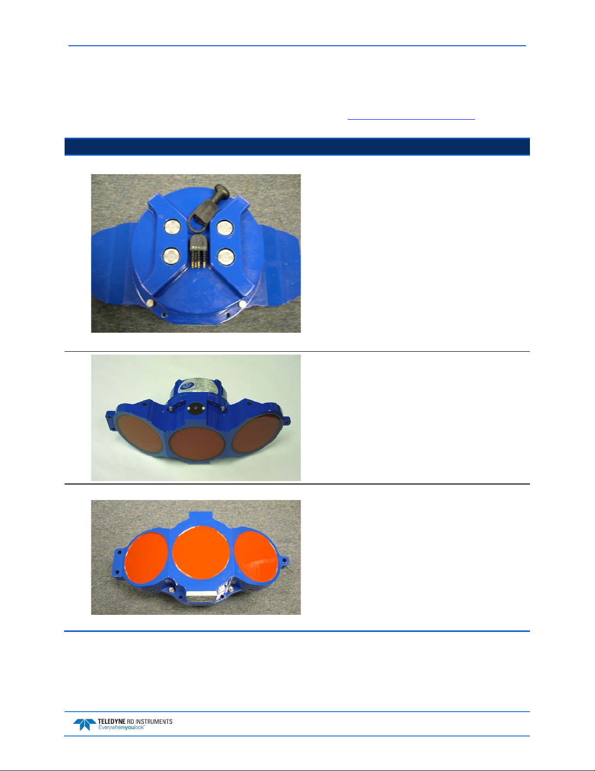
The H-ADCP transducer assembly contains the end-cap, housing, transducer ceramics, and electronics.
The standard acoustic frequencies are 600 and 300 kHz. See the Outline Installation Drawings
sions and weights.
Picture Description
The Input/Output (I/O) cable connects the H-ADCP to the
computer and external power supply. When the cable is not
connected, use the dummy plug to protect the connector.
for dimen-
The optional pressure sensor (standard 200 Bar) measures
water pressure (depth).
The orange urethane faces covers the transducer ceramics.
Never set the transducer on a hard surface. The urethane
faces may be damaged.
The standard H-ADCP housing allows deployment depths to
200 meters.
The H-ADCP electronics and transducer ceramics are
mounted to the transducer head.
EAR-Controlled Technology Subject to Restrictions Contained on the Cover Page.
Page 3
May 2015 WorkHorse H-ADCP Operation Manual
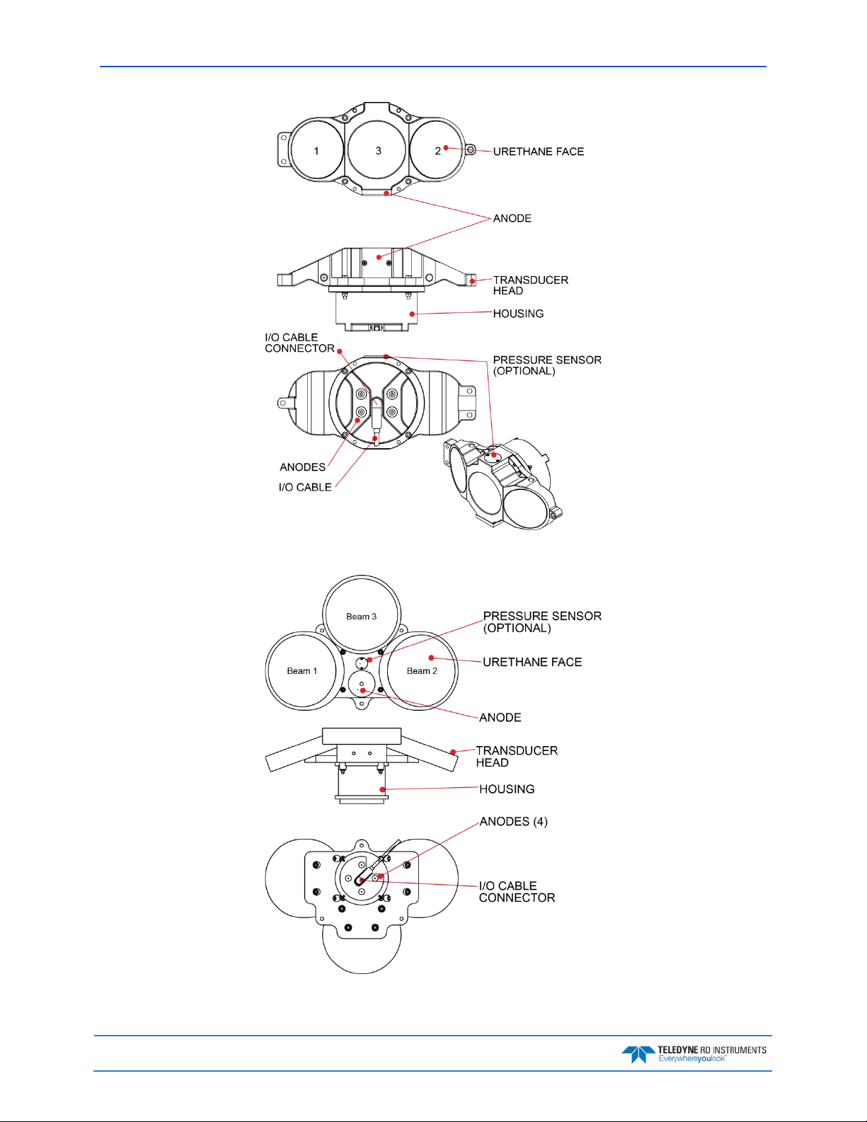
Figure 1. 300/600 kHz H-ADCP Overview
Page 4
Figure 2. 300 kHz NB H-ADCP Overview
EAR-Controlled Technology Subject to Restrictions Contained on the Cover Page.
WorkHorse H-ADCP Operation Manual May 2015
Inventory List
Included with the H-ADCP system:
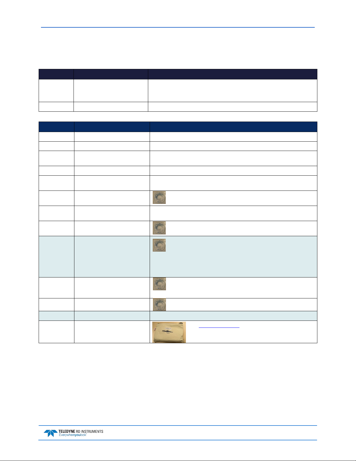
Part Number Name Description
HADCP-I H-ADCP 600 kHz
H-ADCP Accessories Kit Contains the I/O cable, shipping case, software, and documentation listed below.
H-ADCP 300 kHz
H-ADCP 300 kHz Narrow Beam
Included with the H-ADCP Accessories Kit:
Part Number Name Description
73B-3030-005 I/O cable The I/O cable is used for serial communications.
737-3008-025 Extension Cable 25 meter extension cable
717-3014-00
PO3-6
737-3010-00 RS232/RS422 Converter If you ordered RS-422 communications, a RS-232 to RS-422 adapter will be added.
MRDI1004
305D0550-4
90B-8015-00 H-ADCP Documentation CD This CD has PDF versions of all of the H-ADCP documentation. Please read
957-6276-00 H-ADCP Setup Card A printed reference card showing H-ADCP connection and inventory. A PDF version is
907-8040-00 RDI Tools Software CD Utility and testing software package including BBTalk that can be used to
907-8076-00
907-8082-00
907-8029-00 WinSC WinSC works as a shell program to launch the PlanADCP program.
907-8038-00 WinADCP Use the WinADCP program to view data in real-time or playback data files.
AC Power Adapter
Power cord
Shipping case Shipping case with custom foam cutouts.
Waves Software CD (optional)
WavesView Software CD (optional)
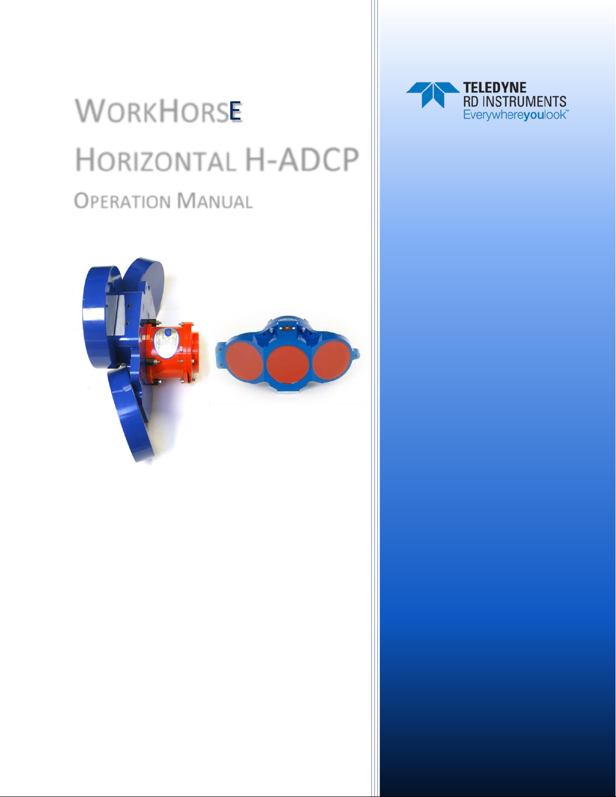
The H-ADCP system includes the transducer and dummy plug.
When unpacking, use care to prevent physical damage to the transducer face and
connector. Use a soft pad to protect the transducer.
AC power adapter provides 48 VDC
the manual!
included on the H-ADCP documentation CD.
test the H-ADCP.
Waves is a feature upgrade for 300 kHz NB H-ADCPs. If you ordered the
directional wave measurement upgrade, WavesMon and WavesView are
included.
WavesMon is the directional wave measurement package for the H-ADCP.
Use WavesView to view wave data. It is an enormously useful tool for turning waves
data into waves information.
PlanADCP is designed to create a command file that will be used to set up
an H-ADCP for collecting data.
757K6085-00 Mounting Kit (optional) Optional mounting kit for 300/600 kHz H-HADCPs
757K6073-00
757K6071-00
Tools and Spare Parts kit See Tools and Spare Parts for a list of parts included in these kits.
EAR-Controlled Technology Subject to Restrictions Contained on the Cover Page.
Page 5

May 2015 WorkHorse H-ADCP Operation Manual
Computer Considerations
TRDI designed the H-ADCP to use a Windows® compatible computer. The computer controls the
H-ADCP and displays its data, usually through our SurfaceView program.
TRDI highly recommends downloading and installing all of the critical updates, recommended
updates, and the service releases for the version of Windows® that you are using prior to
Minimum computer hardware requirements:
• Windows XP®, Windows 7®, Windows 8®
• One Serial Port (two or more High Speed UART Serial Port recommended)
• Minimum display resolution of 1024 x 768, 256 color (higher recommended)
The computer configuration varies depending of the number of communication ports and the external
data refresh rate. Serial communications require a lot of processor resources, and the minimum requirements can vary. A good quality video card is required to operate SurfaceView and WavesMon simultaneously. We do not use graphic card 3D functions; however, video memory is needed to display all graphics.
installing any TRDI software.
SurfaceView runs on Windows XP® only; it will not operate on Windows 7® or 8®.
However, with experience we can recommend that:
• If you are using more than two communication ports, you should not use a Celeron processor.
• Intel Pentium III or higher processors work best to operate the H-ADCP and give access to the
display and keyboard without losing ensembles.
Page 6
EAR-Controlled Technology Subject to Restrictions Contained on the Cover Page.
WorkHorse H-ADCP Operation Manual May 2015
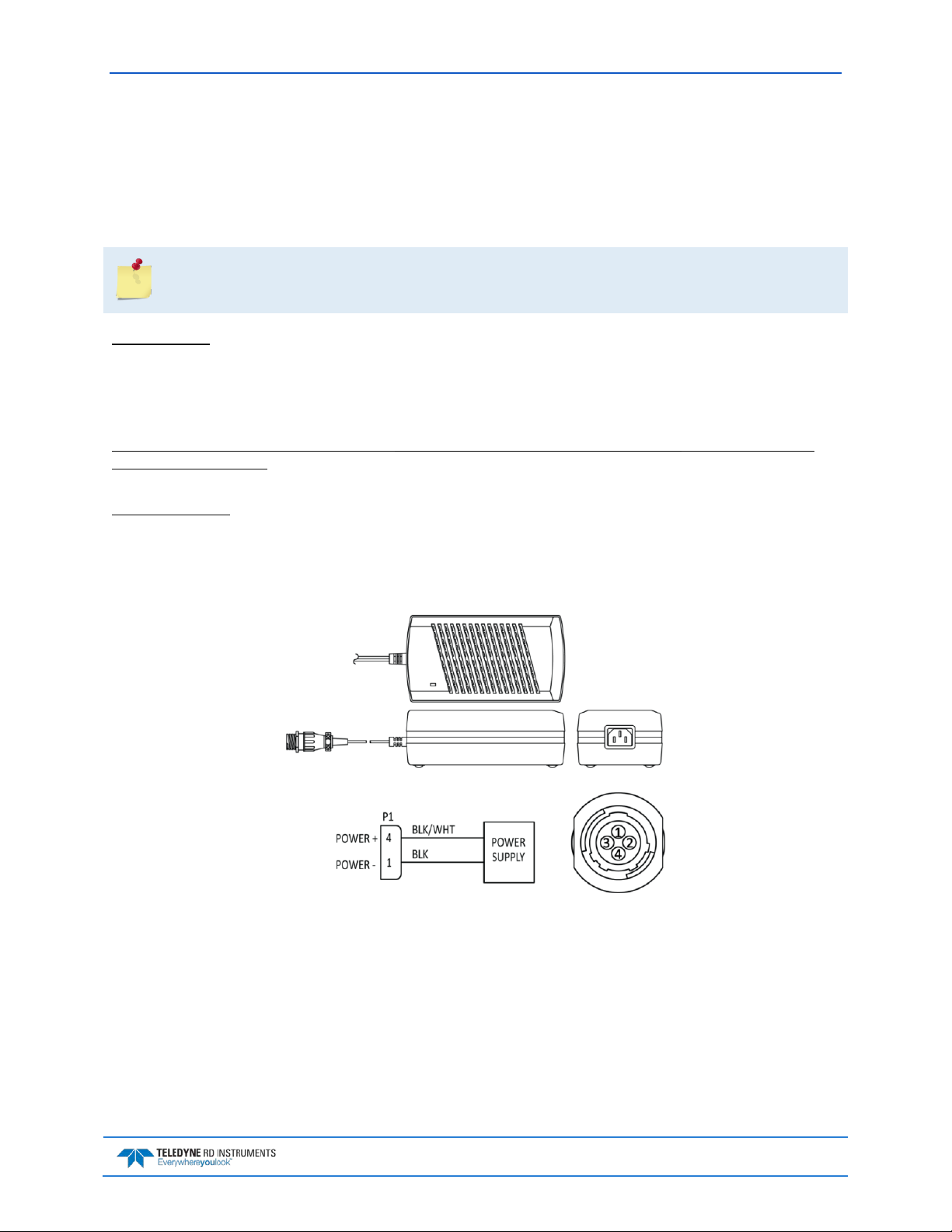
Power Overview
H-ADCP requires +20 to 50 VDC to operate. The AC Adapter runs on any standard AC power and supplies +48 VDC to run the H-ADCP.
Transmitted power increases or decreases depending on the input voltage (within the voltage range of 20
to 50 VDC).
The transmitted power is decreased approximately 1 DB if the input voltage drops from 42 VDC
to 33 VDC. For a 300 kHz H-ADCP, each DB will result in a decrease in range of one default depth
Power on Cycle
The power supply must be able to handle the inrush current as well. Inrush current is the current required
to fully charge up the capacitors when power is applied to the H-ADCP. The capacitors provide a store of
energy for use during transmit. The inrush current is as high as 3 Amps rms. The H-ADCP will draw this
amperage until its capacitors are fully charged.
If the power supply limits the current or the power drop on the cable is significant, then the power on
cycle will take longer. It can take up to one minute. You do not want the power to shut down during the
inrush current draw, as this may not allow the H-ADCP electronics to start.
AC Power Adapter
cell.
The AC power adapter is designed to maintain a 400-ma supply under the H-ADCP’s inrush current. The
adapters are 75-Watt supplies, with 48 VDC, 1.5 amp outputs. They will not fall back to 0 amps, 0 volts
under a load. Customer provided power supplies might shut themselves down under such a load; when
that occurs, the H-ADCP will not wakeup.
Figure 3. AC Power Adapter
EAR-Controlled Technology Subject to Restrictions Contained on the Cover Page.
Page 7
May 2015 WorkHorse H-ADCP Operation Manual
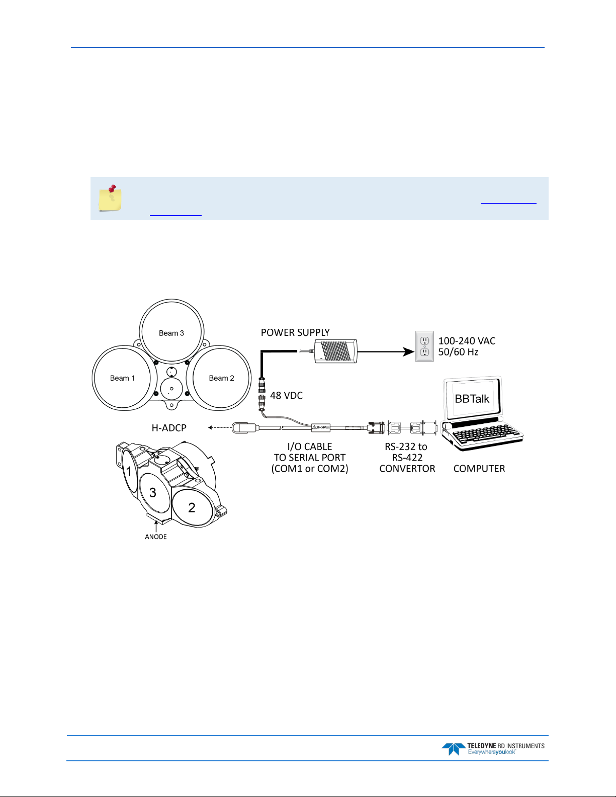
Setting up the H-ADCP System
Use this section to connect the H-ADCP to a computer and establish communications. Install the RDI
Tools software in order to communicate with the H-ADCP.
To set up the H-ADCP:
1. Connect the I/O cable to the H-ADCP. Do so by pushing straight in against the connector. Roll the
retaining strap over the connector.
Place a light amount of dry silicone lubricant spray on the connector pins (rubber portion only).
This will make it easier to connect or remove the I/O cable and dummy plug. See I/O Cable and
Dummy Plug for details.
2. Attach the I/O cable to your computer's communication port. The standard communications settings are RS-232, 9600-baud, no parity, 8 data bits and 1 stop bit.
If the computer uses RS-422 communications, connect the RS-232 to RS-422 adapter.
3. Connect the AC power adapter to the I/O cable.
Page 8
Figure 4. H-ADCP Connections
EAR-Controlled Technology Subject to Restrictions Contained on the Cover Page.

WorkHorse H-ADCP Operation Manual May 2015
Connecting to the H-ADCP
To connect to the H-ADCP:
Start BBTalk
Start the BBTalk program (for help on using BBTalk,
see the RDI Tools User’s Guide).
On the Connect To screen, select WorkHorse.
Select the COM port the H-ADCP cable is connected to.
Click Next.
Enter the Baud Rate, Parity, Stop Bits, and Flow Con-
trol. If you are unsure of the settings, leave them at
the default settings as shown.
Click Next.
Click Finish.
EAR-Controlled Technology Subject to Restrictions Contained on the Cover Page.
Page 9
May 2015 WorkHorse H-ADCP Operation Manual
[BREAK Wakeup B]
>cr1
WorkHorse Horizontal Broadband ADCP Version 11.10
Teledyne RD Instruments (c) 1996-2009
All Rights Reserved.
>
Wakeup
On the File menu, click Break (you can also press the
End key to send a break or press the B button on the
Toolbar).
The wakeup message should appear on the log file
window.
If the H-ADCP does not respond, check the serial port,
cables, AC power, and battery connection (Sentinel
only). If necessary, refer to the Troubleshooting section.
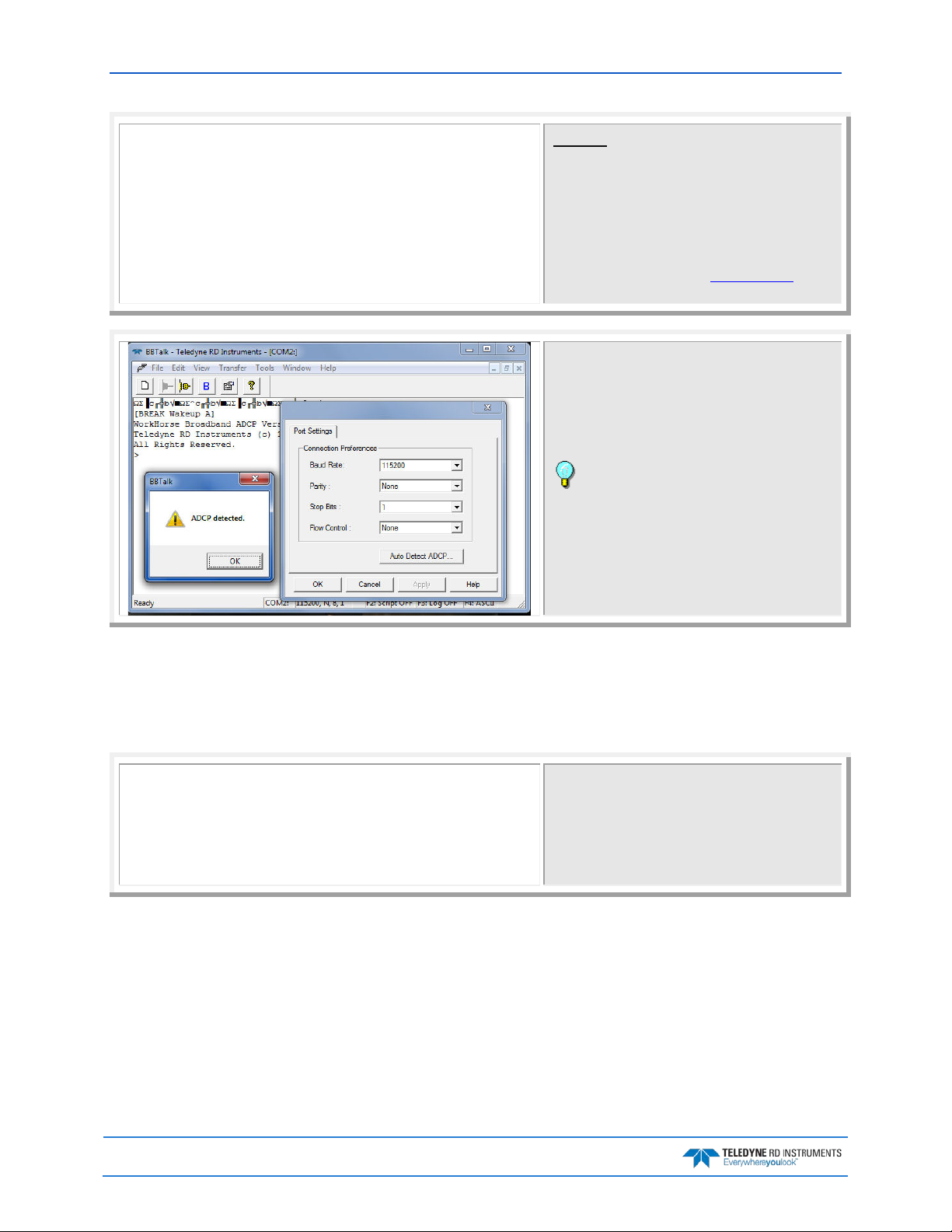
If the wakeup message is not readable or visible:
On the File menu, click Properties.
Click the Auto Detect H-ADCP button.
Click OK when the H-ADCP is detected. Try to wake up
the H-ADCP again.
Both BBTalk and the H-ADCP must use the same
Baud rate.
Testing the H-ADCP
These tests checks that the H-ADCP is able to communicate with the computer and runs the H-ADCP PreDeployment tests.
[Parameters set to FACTORY defaults]
>ck
[Parameters saved as USER defaults]
At the ">" prompt in the communication window,
enter CR1 then press the Enter key. This will set the
H-ADCP to the factory default settings.
At the ">" prompt in the communication window,
enter CK then press the Enter key. This will save the
factory default setting as the default power up condition.
Page 10
EAR-Controlled Technology Subject to Restrictions Contained on the Cover Page.

WorkHorse H-ADCP Operation Manual May 2015
>ps0
>
>pa
>
>Pt3
>
Instrument S/N: 3192
Frequency: 307200 HZ
Configuration: 3 BEAM, HORIZONTAL
Beam Angle: 25 DEGREES
Beam Pattern: CONVEX
Orientation: UP
Sensor(s): HEADING TILT 1 TILT 2 DEPTH TEMPERATURE
PRESSURE
Pressure Sens Coefficients: (c3,c2,c1,offset) 0.00,0.00,0.01,-1.15
Temp Sens Offset: -0.22 degrees C
CPU Firmware: 11.07 [0]
Boot Code Ver: Required: 1.13 Actual: 1.13
DEMOD #1 Ver: ad48, Type: 1f
DEMOD #2 Ver: ad48, Type: 1f
PWRTIMG Ver: 85d3, Type: 6
Board Serial Number Data:
D1 00 00 00 E6 FD 28 09 PIO727-3013-04X
B4 00 00 00 E7 09 74 09 REC727-1015-04X
34 00 00 00 E6 F8 29 09 CPU727-2000-00H
A9 00 00 02 C9 37 69 09 DSP727-2001-04F
PRE-DEPLOYMENT TESTS
CPU TESTS:
RTC......................................PASS
RAM......................................PASS
ROM......................................PASS
RECORDER TESTS:
PC Card #0...............................NOT DETECTED
Card Detect............................PASS
Communication..........................PASS
DOS Structure..........................PASS
Sector Test (short)....................PASS
PC Card #1...............................NOT DETECTED
DSP TESTS:
Timing RAM...............................PASS
Demod RAM...............................PASS
Demod REG...............................PASS
FIFOs....................................PASS
SYSTEM TESTS:
XILINX Interrupts... IRQ3 IRQ3 IRQ3 ...PASS
Receive Loop-Back........................PASS
Wide Bandwidth...........................PASS
Narrow Bandwidth.........................PASS
RSSI Filter..............................PASS
Transmit.................................PASS
SENSOR TESTS:
H/W Operation............................PASS
At the ">" prompt in the communication window,
enter PS0 then press the Enter key. This will display the
H-ADCP system configuration data.
At the ">" prompt in the communication window,
enter the direct command PA then press the Enter key.
This will run the H-ADCP Pre-Deployment tests.
Correlation Magnitude: Narrow Bandwidth
Lag Bm1 Bm2 Bm3
0 255 255 255
1 144 144 146
2 70 71 73
3 37 33 35
4 24 18 18
5 13 12 8
6 6 5 2
7 3 2 1
High Gain RSSI: 71 67 74
Low Gain RSSI: 16 16 18
SIN Duty Cycle: 49 52 49
COS Duty Cycle: 48 50 48
Receive Test Results = $000 ... PASS
At the ">" prompt in the communication window,
enter the direct command PT3 then press the Enter
key. This will run the H-ADCP Receive Path test.
EAR-Controlled Technology Subject to Restrictions Contained on the Cover Page.
Page 11

May 2015 WorkHorse H-ADCP Operation Manual
[BREAK Wakeup B]
>cb?
Changing the Baud Rate in the H-ADCPs
The H-ADCP can be set to communicate at baud rates from 300 to 115200. The factory default baud rate
is always 9600 baud. The baud rate is controlled via the CB-command. The following procedure explains
how to set the baud rate and save it in the H-ADCP. This procedure assumes that you will be using the
program BBTalk that is supplied by Teledyne RD Instruments.
WorkHorse Horizontal Broadband ADCP Version 11.10
Teledyne RD Instruments (c) 1996-2009
All Rights Reserved.
>cr1
[Parameters set to FACTORY defaults]
BAUD RATE CB-command
300 CB011
1200 CB111
2400 CB211
4800 CB311
9600 CB411 (Default)
19200 CB511
38400 CB611
57600 CB711
115200 CB811
CB = 411 ----------------- Serial Port Control (Baud [4=9600]; Par;
Stop)
>cb811
>CK
[Parameters saved as USER defaults]
>cb?
CB = 811 ----------------- Serial Port Control (Baud [8=115200]; Par;
Stop)
>
Connect the H-ADCP to the computer and apply power.
Start the BBTalk program and establish communications with the H-ADCP. Wakeup the H-ADCP by sending
a break signal with the End key.
At the ">" prompt in the communication window, type
CR1 then press the Enter key. This will set the H-ADCP
to the factory default settings.
Send the CB-command that selects the baud rate you
wish. The table on the left shows the CB-command
settings for different baud rates with no parity and 1
stop bit.
For example, to change the baud rate to 115200, at
the ">" prompt in the communication window, type
cb811 then press the Enter key.
The CB? command will identify the communica-
tion setting.
BBTalk will send the command CK to save the new
baud rate setting.
Exit BBTalk.
The H-ADCP is now set for the new baud rate. The
baud rate will stay at this setting until you change it
back with the CB command.
Page 12
Exit BBTalk so the communication port is availa-
ble for use with other programs.
EAR-Controlled Technology Subject to Restrictions Contained on the Cover Page.

WorkHorse H-ADCP Operation Manual May 2015
Caring for the H-ADCP System
This section contains a list of items you should be aware of every time you handle, use, or deploy your
H-ADCP. Please refer to this list often.
General Handling Guidelines
• Never set the transducer on a hard or rough surface. The urethane faces may be damaged.
• Always remove the retaining strap on the underwater-connect cable and dummy plug when dis-
connecting them. Failure to do so will break the retainer strap.
• Do not apply any upward force on the end-cap connector as the I/O cable is being disconnected.
Stressing the connector may cause the H-ADCP to flood. Read the Installation section
details on disconnecting the I/O cable.
• Do not expose the transducer faces to prolonged sunlight. The urethane f ac es may develop
cracks. Cover the transducer faces on the H-ADCP if it will be exposed to sunlight.
• Do not expose the I/O connector to prolonged sunlight. The plastic may become brittle. Cov-
er the connector on the H-ADCP if it will be exposed to sunlight.
• Do not store the H-ADCP in temperatures over 60 degrees C. The urethane faces may be
damaged.
for
• Vent the system before opening by loosening the hardware on the housing. If the H-ADCP
flooded, there may be gas under pressure inside the housing.
• Do not scratch or damage the O-ring surfaces or grooves. If scratches or damage exists, they
may provide a leakage path and cause the H-ADCP to flood. Do not risk a deployment
with damaged O-ring surfaces.
• Do not lift or support an H-ADCP by the external I/O cable. The connector or cable will
break.
• The 300 kHz NB H-ADCP should only be lifted by holding onto the transducer mounting plate.
Do not lift by holding onto the housing, end-cap, or beams. The system weight can cause se-
rious damage to the H-ADCP or personnel lifting the unit. Use the
Drawings to locate the transducer mounting plate.
Outline Installation
Assembly Guidelines
• Read the Maintenance section for details on H-ADCP re-assembly. Make sure the housing assem-
bly O-ring stays in the groove when you re-assemble the H-ADCP. Tighten the hardware as specified. Loose, missing, stripped hardware, or a damaged O-ring can cause the H-ADCP
transducer to flood.
TM
• Use light amounts of silicone lubricant (such as 3M
4678-4930-3) on both the male pins and female socket to help seat the cable connectors. Wipe off
excessive silicone spray from the metal portions of the pins. Regular lubrication is required:
Apply dry type silicone lubricant prior to each connection.
Silicone Lubricant (Dry Type) ID No: 62-
• Do not connect or disconnect the I/O cable with power applied. When you connect the cable with
power applied, you may see a small spark. The connector pins may become pitted and
worn.
• The H-ADCP I/O cable may be connected while slightly wet; do not connect under water.
EAR-Controlled Technology Subject to Restrictions Contained on the Cover Page.
Page 13

May 2015 WorkHorse H-ADCP Operation Manual
Deployment Guidelines
• Read the Software User’s Guides. These guides have tutorials to help you learn how to
collect data with the H-ADCP.
• Align the compass whenever any ferrous metals are relocated inside or around the H-ADCP hous-
ing. Ferro-magnetic materials affect the compass.
• The AC power adapter is not designed to withstand water. Use caution when using on decks
in wet conditions.
• Avoid using ferro-magnetic materials in the mounting fixtures or near the H-ADCP. Ferro-
magnetic materials affect the compass.
• Your H-ADCP transducer housing and mounting plate is made of aluminum. Do not connect oth-
er metal to the H-ADCP. Other metals may cause corrosion damage. Use isolating bush-
ings when mounting the H-ADCP to a metal structure. Keep this in mind when fabricating a fixture, which materials to use, or deciding how to place it at the installation site.
• Sacrificial anodes are fitted to the H-ADCP to prevent corrosion (see
Zinc Anode Inspection and
Replacement). Standard anode protection will typically protect the parts that may corrode. How-
ever, you should plan regular inspections of the mounting hardware for signs of cor-
rosion. TRDI disposes many corroded hardware sets during inspections.
• Inspect the paint on the end-cap, housing, and transducer assemblies for corrosion, scratches,
cracks, abrasions, paint blisters, exposed metal (silver-colored aluminum), exposed anodize
(black or dark green), and exposed primer (yellow). Be critical in your judgment; the useful
life of the H-ADCP depends on it. See Protective Coating Inspection and Repair
for details.
Page 14
EAR-Controlled Technology Subject to Restrictions Contained on the Cover Page.

WorkHorse H-ADCP Operation Manual May 2015
I
Chapter 2
NSTALLATION
In this chapter, you will learn:
• How to connect/disconnect the I/O cable
• How to connect the optional external battery case
• Cable wiring diagrams
• Available mounts for the WorkHorse H-ADCP
EAR-Controlled Technology Subject to Restrictions Contained on the Cover Page.
Page 15

May 2015 WorkHorse H-ADCP Operation Manual
I/O Cable and Dummy Plug
The underwater connector (on the housing) and the I/O cable and dummy plug are molded wet-mate
connectors.
The dummy plug should be installed any time the cable is removed. Use the dummy plug when
the H-ADCP is in storage or is being handled.
When disconnecting or connecting the H-ADCP I/O cable, do not apply any upward force on the
connector. Applying an upward angle as the cable is disconnected or connected puts stress on
the connector. This may cause several serious problems:
a) The connector or connector pins can crack.
Disconnecting the Cable
To disconnect the cable:
1. Release the retaining strap by pulling it over the connector.
b) The O-ring on the bottom of the connector can be damaged.
c) The molded urethane on the connector may separate from the brass insert.
If the connector is damaged in any of these ways, your H-ADCP will flood.
2. Grasp the cable close to the housing (see Figure 5). Your thumb should rest against the edge of the
housing. Do not try to fit your hand under the cable as it passes over the housing. This is what
causes the upward force!
3. Pull the cable straight out away from the housing. Avoid side-to-side rocking motions as much as
possible. Do not apply any upward force on the connector as it is being disconnected.
Figure 5. Removing the I/O Cable
Page 16
EAR-Controlled Technology Subject to Restrictions Contained on the Cover Page.
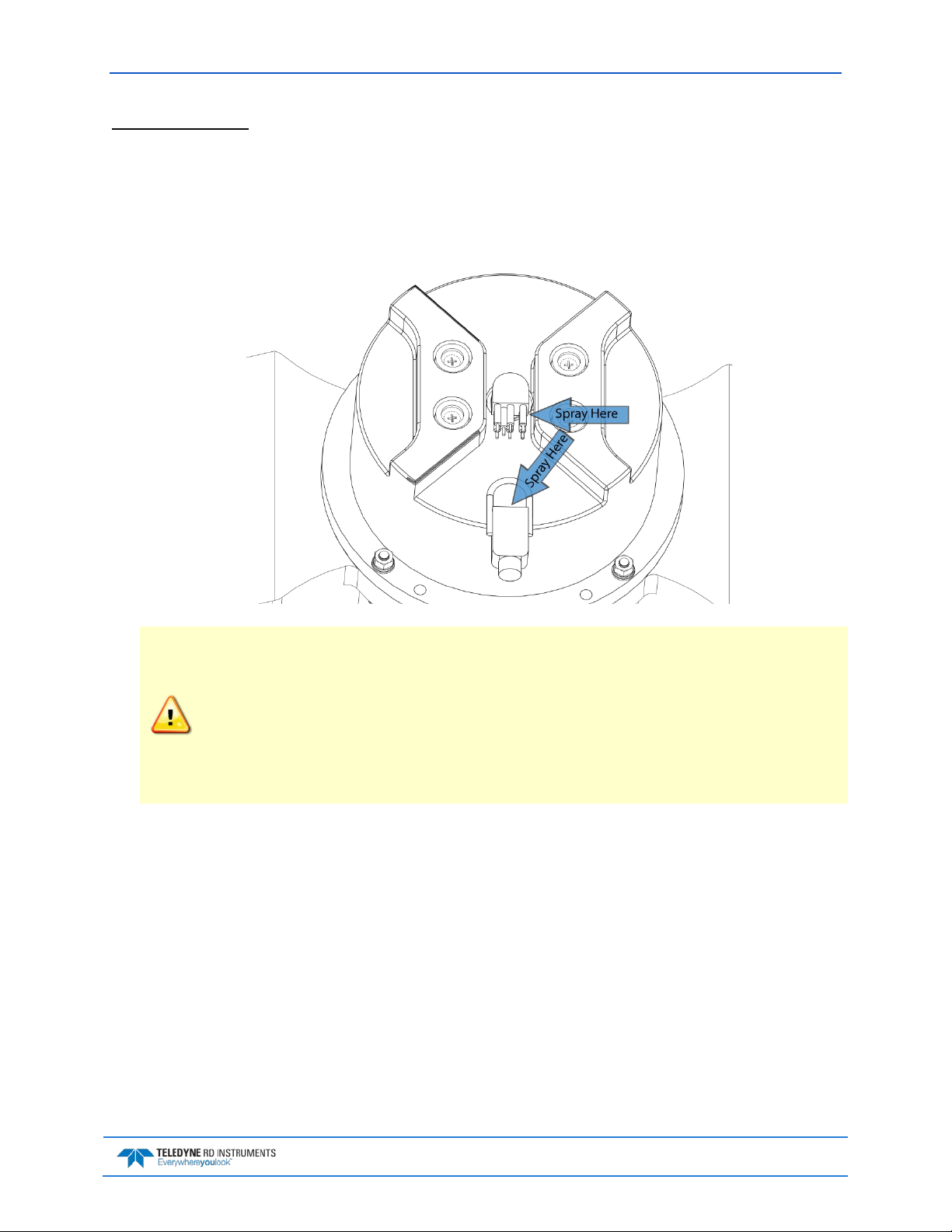
WorkHorse H-ADCP Operation Manual May 2015
Connecting the Cable
To connect the cable:
1. Check all pins for signs of corrosion (greenish oxidation, black deposits, or pitting).
TM
2. Use light amounts of silicone lubricant (such as 3M
Silicone Lubricant (Dry Type) ID No: 62-
4678-4930-3) on both the male pins and female socket to help seat the cable connectors. Wipe off
excessive silicone spray from the metal portions of the pins. Regular lubrication is required:
Apply dry type silicone lubricant prior to each connection.
When the cable is connected without any lubricant, excessive force is needed to fully seat or
remove the connector. This can cause several serious problems:
• The neoprene rubber portion of the contact pin may tear from the metal pin.
• Wiggling the cable side-to-side to overcome the friction as it is connected or
disconnected may cause the neoprene rubber to tear or create pin-holes on the side of
the connector.
As a result of any damage to the neoprene rubber, corrosion may occur on current carrying
pins.
3. Gently push the cable straight in toward the connector. Do not apply any upward force on the
connector as it is being connected.
4. Roll the retaining strap over the connector.
EAR-Controlled Technology Subject to Restrictions Contained on the Cover Page.
Page 17
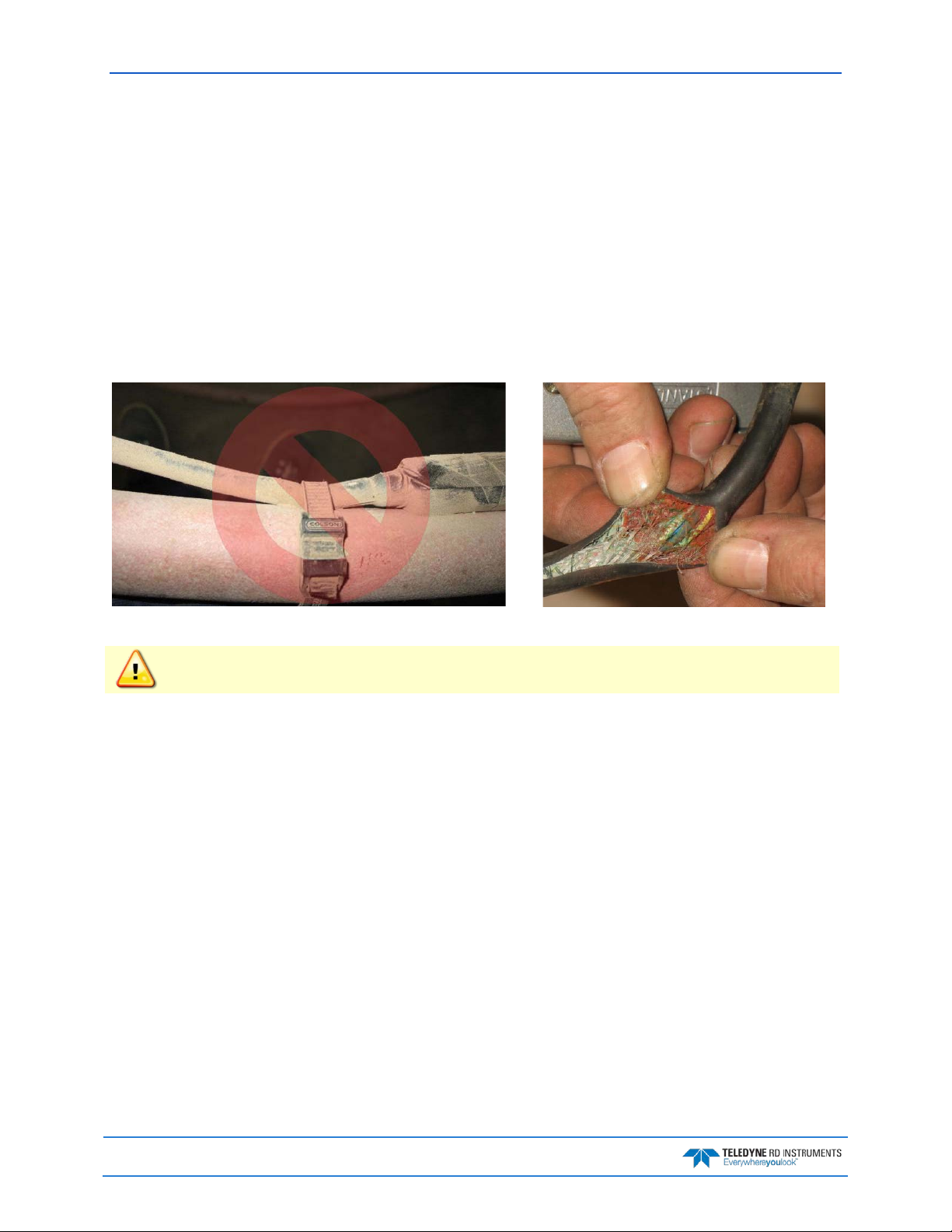
May 2015 WorkHorse H-ADCP Operation Manual
Routing Cables
Use care when routing the cable through bulkheads, deck plates, cable runs, and watertight spaces. Make
allowances in cable length and engineering design plans for cable routing. When necessary, use strain reliefs on the cables.
Route this cable so:
• It does not have kinks or sharp bends.
• Protect the cables with hose if zip-ties are used to secure them to structures (see Figure 6).
• The cable can easily be replaced it if it fails.
• The cable connector is not spliced. The wet-end connector is 3.0cm (1.18 inches) long, 2.54cm
(1.00 inches) wide, 1.27cm (0.5 inches) high. Model# Impulse LPMIL-7-FS.
Figure 6. Do not use Zip-Ties Directly on Cables
When attaching the H-ADCP cables to your mount, do not zip-tie the cables directly to the
structure. Zip-ties slowly cut through the cable’s outer jacket and cause leaks.
Page 18
EAR-Controlled Technology Subject to Restrictions Contained on the Cover Page.
 Loading...