

Page 1

Operator’s
Manual
WaveLink Series
Differential Probe
(4, 6 GHz)
Page 2

Page 3

Page 4

Page 5

Introduction ................................................................................................................................ 1
Modular Advantage .................................................................................................................... 2
Modular Probe Components ....................................................................................................... 5
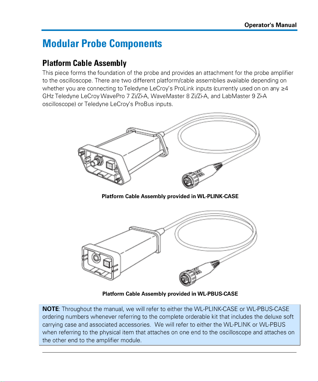
Platform Cable Assembly .......................................................................................................... 5
Differential Amplifier Small Tip Modules .................................................................................. 7
Interconnect Leads ................................................................................................................... 8
Optional Accessories................................................................................................................. 9
Adjustable Tip Module ............................................................................................................ 10
Probe Operation ....................................................................................................................... 12
Handling the Probe ................................................................................................................. 12
Connecting an Amplifier Module to a Probe Body ................................................................. 12
Connecting the Lead to the Amplifier ..................................................................................... 13
Connecting the Hi-Temp SI Interconnect Lead to the Amplifier ............................................. 13
Interchangeability and Calibration ......................................................................................... 14
Compatibility .......................................................................................................................... 14
Connecting the Probe to a Teledyne LeCroy Oscilloscope ..................................................... 14
Operation with a Teledyne LeCroy Oscilloscope .................................................................... 15
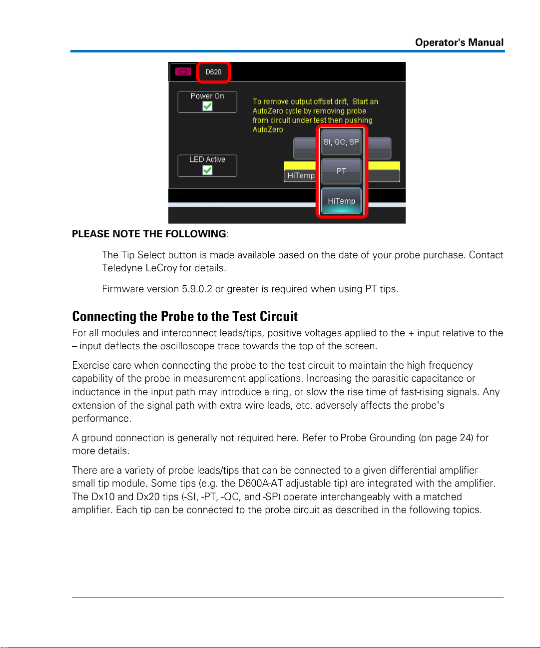
Connecting the Probe to the Test Circuit ............................................................................... 17
Positioning of the Input Leads ................................................................................................ 24
Autocolor ID ............................................................................................................................ 25
Power Control ......................................................................................................................... 26
AutoZero ................................................................................................................................. 27
Accessory Use ........................................................................................................................... 27
Positioning Tools ..................................................................................................................... 27
Probe Deskew Fixture ............................................................................................................. 37
Probe Characterizing .............................................................................................................. 38
Care and Maintenance .............................................................................................................. 42
Care and Maintenance Overview ........................................................................................... 42
Replacing Tips and Sockets on Dx10-PT and Dx20-PT ............................................................ 43
Service Strategy ...................................................................................................................... 44
Returning a Probe for Calibration or Service .......................................................................... 44
Page 6

Returning a Probe to a Different Country ............................................................................... 46
Consumables and Replacement Parts ..................................................................................... 47
Service Options ....................................................................................................................... 54
Functional Test ......................................................................................................................... 56
Functional Test Overview........................................................................................................ 56
Test Setup ............................................................................................................................... 56
Performance Verification ......................................................................................................... 61
Performance Verification Overview ........................................................................................ 61
Required Test Equipment ....................................................................................................... 62
Preliminary Procedure ............................................................................................................ 64
Verification Procedure ............................................................................................................ 65
Reference Material ................................................................................................................... 78
Specifications .......................................................................................................................... 78
Regional Service Centers ......................................................................................................... 78
Warranty ................................................................................................................................. 80
Safety Instructions .................................................................................................................. 80
Certifications ........................................................................................................................... 81
Probe Input Loading ................................................................................................................ 83
Differential Mode and Common Mode ................................................................................... 93
Differential Mode Range and Common Mode Range ............................................................. 94
Common Mode Rejection Ratio .............................................................................................. 95
Offset ...................................................................................................................................... 96
Dynamic Range ....................................................................................................................... 97
Appendix A - Performance Verification Test Record ................................................................. 98
Items Tested............................................................................................................................ 98
Equipment Used ...................................................................................................................... 98
Test Record ............................................................................................................................. 99
Page 7

923175-00 Rev A
1
Page 8

2
923175-00 Rev A
Page 9

923175-00 Rev A
3
Standard Accessories
WL-PBUS-CASE
WL-PLINK-CASE
Dx10/20
Dx10/20-
PS
Dx10/20-
PT-KIT
Dx10/20-
SI-HiTemp
Dx00A-
AT
Amplifier System
Amplifier
-
1 each
1 each
- - -
Solder-in Lead Set
-
1 each
1 each
- - -
Spare Damping Resistors for
SI Tip
-
1 set of 5
1 set of 5
- - -
Tip Retaining Clip for
SI Leads
-
1 each
1 each
- - Adhesive Tape
-
1 set
1 set - - - Quick Connect Lead Set
-
1 each
1 each
- - -
Damping Resistors for QC Tip
-
2 sets of
10
2 sets of
10
- Square Pin Lead Set
-
1 each
1 each
- - -
Ground Lead
-
1 each
1 each
- - -
Ground Clip
-
1 each
1 each
- - -
Instruction Manual
-
1 each
1 each
- - 1 each
Accessory Info Sheet &
Quick Start Guide
-
1 each
1 each
- - HiTemp SI Lead
-
-
-
-
1 each
-
HITemp Cable
-
-
-
-
1 matched
set - Positioner Tip with Accessories
-
-
- - -
Positioner Tip (Browser)
-
-
1 each
1 each
-
-
Replacement Pogo Pins for
Dx10-PT/Dx20-PT
-
-
1 set
1 set - Positioner Tip Probe Guides
-
-
1 each
1 each
-
-
Page 10

4
923175-00 Rev A
Standard Accessories
WL-PBUS-CASE
WL-PLINK-CASE
Dx10/20
Dx10/20-
PS
Dx10/20-
PT-KIT
Dx10/20-
SI-HiTemp
Dx00A-
AT
XYZ Positioner
-
-
1 each
1 each
-
-
Adhesive Tape for
XYZ Positioner
-
-
1 set
1 set - Browser Wand for PT Tip
-
-
1 each
1 each
- - Interlock Pieces for PT Tip
-
-
1 each
1 each
- - Swivel for PT Tip
-
-
1 each
1 each
- - Platform/Cable Assembly Kit
Platform/Cable Assembly
1 each
-
1 each
- - -
Freehand Probe Holder
1 each
-
1 each
- - -
Probe Deskew Fixture
1 each
-
1 each
- - -
Platform/Cable Assembly
Mounting Clip
1 each
-
1 each
-
1 each
1 each
Probe Cable Clamp
2 each
-
2 each
-
1 each
1 each
Deluxe Soft Carrying Case
1 each
-
1 each
- - -
Foam Insert for Carrying Case
1 each
-
1 each
- - -
Protective Storage Case
1 each
-
1 each
- - -
Plastic Tray for Storage Case
1 each
-
1 each
- - -
Page 11
923175-00 Rev A
5
Page 12

6
923175-00 Rev A
Platform/Cable Assembly
Product Code
WaveLink ProLink Probe Platform/Cable Assembly
WL-PLINK-CASE
WaveLink ProBus Platform/Cable Assembly
WL-PBUS-CASE
Page 13

923175-00 Rev A
7
Amplifier Modules (incl. Solder-in or Adjustable Tip)
Product
Code
WaveLink D410 4 GHz/2.5Vp-p Differential Probe Amplifier with Dx10-SI Solder-In Tip (Qty.
1), Dx10-SP Square Pin (Qty. 1), and Dx10-QC Quick Connect (Qty. 1)
D410
WaveLink D420 4 GHz/5Vp-p Differential Probe Amplifier with Dx20-SI Solder-In Tip (Qty. 1),
Dx20-SP Square Pin (Qty. 1), and Dx20-QC Quick Connect (Qty. 1)
D420
WaveLink D610 6 GHz/2.5Vp-p Differential Probe Amplifier with Dx10-SI Solder-In Tip (Qty.
1), Dx10-SP Square Pin (Qty. 1), and Dx10-QC Quick Connect (Qty. 1)
D610
WaveLink D620 6 GHz/5Vp-p Differential Probe Amplifier with Dx20-SI Solder-In Tip (Qty. 1),
Dx20-SP Square Pin (Qty. 1), Dx20-QC Quick Connect (Qty. 1)
D620
WaveLink D400A-AT 4 GHz/4.8Vp-p Differential Amplifier Module with Adjustable Tip
D400A-AT
WaveLink D600A-AT 6 GHz/4.8Vp-p Differential Amplifier Module with Adjustable Tip
D600A-AT
Page 14

8
923175-00 Rev A
Page 15

923175-00 Rev A
9
Page 16

10
923175-00 Rev A
Standard Accessories
D4x0-PS
D6x0-PS
WL-PBUS-Case Platform/Cable Assembly
1 Each
WL-PLINK-Case Platform/Cable Assembly
1 Each
Dxx0 Amplifier Module with SI, SP, and QC Lead Sets
1 Each
1 Each
Dxx0-PT-KIT Positioner Tip (Browser) Kit
1 Each
1 Each
Page 17

923175-00 Rev A
11
Page 18

12
923175-00 Rev A
Page 19

923175-00 Rev A
13
Page 20

14
923175-00 Rev A
Platform/Cable
Assembly
Probe Tip Module
Adjustable and Small Tip Modules
D410, D420, and D400A-AT
Adjustable and Small Tip Modules
D610, D620, and D600A-AT
WL-PLINK
Allowed
Allowed
WL-PBUS
Allowed
Reduced BW
Page 21

923175-00 Rev A
15
Page 22

16
923175-00 Rev A
Page 23
923175-00 Rev A
17
Page 24

18
923175-00 Rev A
Page 25

923175-00 Rev A
19
Inserting square pins or wires other than the ones provided with the QC lead may cause
damage to the wire receptacle.
Page 26

20
923175-00 Rev A
Page 27

923175-00 Rev A
21
Page 28

22
923175-00 Rev A
Page 29

923175-00 Rev A
23
Page 30

24
923175-00 Rev A
Page 31

923175-00 Rev A
25
Page 32

26
923175-00 Rev A
Temperature °C
Time
Up to 40
Continuous
40 to 55
40 minutes
55 to 65
18 minutes
65 to 75
30 seconds
75 to 85
15 seconds
Page 33

923175-00 Rev A
27
Page 34

28
923175-00 Rev A
Page 35

923175-00 Rev A
29
Page 36

30
923175-00 Rev A
Page 37

923175-00 Rev A
31
Page 38

32
923175-00 Rev A
Page 39

923175-00 Rev A
33
Page 40

34
923175-00 Rev A
Page 41

923175-00 Rev A
35
Page 42

36
923175-00 Rev A
Page 43

923175-00 Rev A
37
o
o
Page 44

38
923175-00 Rev A
Page 45

923175-00 Rev A
39
Page 46

40
923175-00 Rev A
Page 47

923175-00 Rev A
41
Page 48

42
923175-00 Rev A
Page 49

923175-00 Rev A
43
Page 50

44
923175-00 Rev A
Page 51

923175-00 Rev A
45
Page 52

46
923175-00 Rev A
Page 53

923175-00 Rev A
47
Description and
Initial Product Code
Image
Replacement Product
Code
Positioner Tip with
Accessories
Dx10-PT-Kit
(D610/D410)
Dx20-PT-Kit
(D620/D420)
RK-Dx10-PT-Kit
RK-Dx20-PT-Kit
Positioner Tip
(Only ordered as a
replacement.)
Dx10-PT (D610/D410)
Dx20-PT (D620/D420)
Pogo Pin Tips
(for PT Tip)
(Only ordered as a
replacement.)
Dxx0-PT-Tips
(Included with
D6x0-PT-Kit /
D4x0-PT-Kit)
(Qty. 4)
Page 54

48
923175-00 Rev A
Description and
Initial Product Code
Image
Replacement Product
Code
Pogo Tip
Connection Guides
(Only ordered as a
replacement.)
Dxx0-PT-Guides
(Included with
D6x0-PT-Kit /
D4x0-PT-Kit)
XYZ Positioner
(Only ordered as a
replacement.)
Dxx0-PT-XYZ-Positioner
(Included with
D6x0-PT-Kit /
D4x0-PT-Kit)
Adhesive Tape for
XYZ Positioner
(Only ordered as a
replacement.)
Dxx0-PT-Tape
(Included with
D6x0-PT-Kit /
D4x0-PT-Kit)
(10 Pcs. Each)
Browser Wand for
PT Tip
(Only ordered as a
replacement.)
Dxx0-PT-Wand
(Included with
D6x0-PT-Kit /
D4x0-PT-Kit)
(Qty. 1)
Page 55

923175-00 Rev A
49
Description and
Initial Product Code
Image
Replacement Product
Code
Interlock Pieces for
PT Tip
(Only ordered as a
replacement.)
Dxx0-PT-Interlock
(Included with
D6x0-PT-Kit /
D4x0-PT-Kit)
(6 Pcs.)
Swivel for PT Tip
(Only ordered as a
replacement.)
Dxx0-PT-Swivel
(Included with
D6x0-PT-Kit /
D4x0-PT-Kit)
(Qty. 1)
Solder-In Tips
(Only ordered as a
replacement.)
PKxx0-SI (D6x0/D4x0)
(Qty. 5)
Solder-In Lead
(Only ordered as a
replacement. Also,
includes PK600ST-3.)
Dx10-SI (D610/D410)
Dx20-SI (D620/D420)
Page 56

50
923175-00 Rev A
Description and
Initial Product Code
Image
Replacement Product
Code
Replacement
HiTemp-SI Lead
Dx10-SI-HiTemp
(D610/D410)
Dx20-SI-HiTemp
(D620/D420)
With Spare Resistors
(Qty. 10)
Replacement Quick
Connect Lead
Dx10-QC (D610/D410)
Dx20-QC (D620/D420)
With Spare Resistors
(Qty. 10)
Page 57

923175-00 Rev A
51
Description and
Initial Product Code
Image
Replacement Product
Code
Replacement Square
Pin Lead
(Only ordered as a
replacement.)
Dx10-SP (D610/D410)
Dx20-SP (D620/D420)
With Spare Resistors
(Qty. 10)
Replacement
HiTemp Cable
(Only ordered as a
replacement.)
Dxx0-Cable-HiTemp
(1 Paired Cable Each)
Replacement
Solder-In Probe
Holder Kit
(Only ordered as a
replacement. Includes 2
tip retaining clips and 1
set of adhesive tape.)
PK600ST-3
(Included as part of
D6x0/D4x0.)
Page 58

52
923175-00 Rev A
Description and
Initial Product Code
Image
Replacement Product
Code
Ground Lead
(Only ordered as a
replacement. Includes 4
leads.)
PACC-LD005
(Included as part of
D6x0/D4x0.)
Ground Clip
(Only ordered as a
replacement. Includes 2
clips.)
PK006-4
(Included as part of
D6x0/D4x0.)
Platform/Cable
Assembly Mounting
Kit
(Only ordered as a
replacement.)
PK600ST-4
(Included as part of WL-
PLINK-CASE and WLPBUS-CASE).
Probe Deskew
Fixture
(Only ordered as a
replacement.)
PCF200
(Included as part of WL-
PLINK-CASE and WLPBUS-CASE)
Freehand Probe
Holder
(Only ordered as a
replacement.)
PACC-MS001
(Included as part of WL-
PLINK-CASE and WLPBUS-CASE)
Page 59

923175-00 Rev A
53
Description and
Initial Product Code
Image
Replacement Product
Code
Deluxe Soft
Carrying Case
(Only ordered as a
replacement)
SAC-03
(Included as part of WL-
PBUS--CASE, WLPLINK-CASE, Dx10-PS,
Dx20-PS)
Foam Insert for
SAC-03
921079-00 for
WL-PBUS-CASE;
921081-00 for
WL-PLINK-CASE
Protective
Storage Case
(Only ordered as a
replacement)
921083-00
(Included as part of WP-
PBUS-CASE,
WL-PLINK-CASE,
Dx10-PS, Dx20-PS)
Plastic Tray for
Protective
Storage Case
(Only ordered as a
replacement)
921078-00
(Included as part of WP-
PBUS-CASE,
WL-PLINK-CASE,
Dx10-PS, Dx20-PS)
Page 60

54
923175-00 Rev A
Service Option
Product Code
Three-Year Warranty for D600A-AT
D600A-AT-W3
Three-Year Warranty for D400A-AT
D400A-AT-W3
Three-Year Warranty for D610
D610-W3
Three-Year Warranty for D620
D620-W3
Three-Year Warranty for D410
D410-W3
Three-Year Warranty for D420
D420-W3
Five-Year Warranty for D600A-AT
D600A-AT-W5
Five-Year Warranty for D400A-AT
D400-AT-W5
Five-Year Warranty for D610
D610-W5
Five-Year Warranty for D620
D620-W5
Five-Year Warranty for D410
D410-W5
Five-Year Warranty for D420
D420-W5
Three-Year Warranty and Annual NIST Calibration
D600A-AT-T3
Three-Year Warranty and Annual NIST Calibration
D400A-AT-T3
Three-Year Warranty and Annual NIST Calibration
D610-T3
Three-Year Warranty and Annual NIST Calibration
D620-T3
Three-Year Warranty and Annual NIST Calibration
D410-T3
Three-Year Warranty and Annual NIST Calibration
D420-T3
Five-Year Warranty and Annual NIST Calibration
D600A-AT-T5
Five-Year Warranty and Annual NIST Calibration
D400-A-AT-T5
Five-Year Warranty and Annual NIST Calibration
D610-T5
Five-Year Warranty and Annual NIST Calibration
D620-T5
Five-Year Warranty and Annual NIST Calibration
D410-T5
Five-Year Warranty and Annual NIST Calibration
D420-T5
Page 61

923175-00 Rev A
55
Service Option
Product Code
Three-Year Annual NIST Calibration
D600A-AT-C3
Three-Year Annual NIST Calibration
D400A-AT-C3
Three-Year Annual NIST Calibration
D610-C3
Three-Year Annual NIST Calibration
D620-C3
Three-Year Annual NIST Calibration
D410-C3
Three-Year Annual NIST Calibration
D420-C3
Five-Year Annual NIST Calibration
D600A-AT-C5
Five-Year Annual NIST Calibration
D400A-AT-C5
Five-Year Annual NIST Calibration
D610-C5
Five-Year Annual NIST Calibration
D620-C5
Five-Year Annual NIST Calibration
D410-C5
Five-Year Annual NIST Calibration
D420-C5
NIST Traceable Calibration with Test Data*
(one module)
D600A-AT-CCNIST
D400A-AT-CCNIST
D610-CCNIST
D620-CCNIST
D410-CCNIST
D420-CCNIST
Page 62

56
923175-00 Rev A
1.
2.
Page 63

923175-00 Rev A
57
3.
4.
5.
Page 64

58
923175-00 Rev A
6.
7.
8.
→
Page 65

923175-00 Rev A
59
9.
10.
11.
12.
13.
14.
Page 66

60
923175-00 Rev A
15.
16.
17.
18.
19.
20.
Page 67

923175-00 Rev A
61
Page 68

62
923175-00 Rev A
Description
Minimum Requirements
Example Test Equipment
Oscilloscope, High BW 1
BW ³ 6 GHz
Teledyne LeCroy: WaveMaster 8600A,
WavePro 760 Zi, WaveMaster 806 Zi/Zi-A
Oscilloscope, High BW 2
BW ³ 4 GHz
Teledyne LeCroy: WaveMaster 804Zi-A,
WavePro 740 Zi, WaveRunner 640 Zi
Oscilloscope, High Impedance
200 mV/div - 2 V/div scale
factor 1 MΩ input impedance
ProBus interface
Teledyne LeCroy: WavePro 7300 or
WaveRunner 6200, WavePro 735 Zi-A,
WaveRunner 6 Zi
Digital Multimeter
AC: 0.2% accuracy to
measure 200 mV and 2 V
rms
@
1 kHz 6½ digit resolution
Agilent Technologies: 34401A, or Fluke:
8842A-09, or Keithley: 2001
Oscillator/Function Generator
Sine Wave output, adjustable
from 500 mV to 4 Vp-p (357
mV to 2.83 V
rms
) at 70 Hz
Stanford Research: Model DS340,or
Agilent Technologies: 33120A, or Leader:
LAG-120B
Pulse Generator
12 ps, -5 V
out
, 2.4 mm output
Picosecond Pulse Labs: 4015D-215
Calibration Fixture 3
See Preliminary Procedure
Teledyne LeCroy: ProLink-CF01
Calibration Fixture 4
See Preliminary Procedure
Teledyne LeCroy: ProBus-CF01
Terminator, Precision, BNC
50 Ω ± 0.05%
Teledyne LeCroy: TERM-CF01
Characterization Fixture 5
Teledyne LeCroy: PCF-200
SMA to BNC Adapter
Female SMA to male BNC
Pomona Electronics: 4289
Page 69

923175-00 Rev A
63
Description
Minimum Requirements
Example Test Equipment
Pasternack Enterprises: PE9073
SMA to BNC adapter
Male SMA to female BNC
Pomona Electronics: 4290
Pasternack Enterprises: PE9074
SMA to BNC Adapter
Female SMA to female BNC
Pomona Electronics: 4291
Pasternack Enterprises: PE9075
SMA to SMA Adapter 6
Female SMA to female SMA
Pomona Electronics: 4284
Pasternack Enterprises: PE9070
Terminator, SMA
Female SMA, 50 Ω, ½ W
Pomona Electronics: 4287
Pasternack Enterprises: PE6003
Attenuator
Male 2.4 mm to male SMA, 50
Ω, 10 dB,12 GHz
Pasternack Enterprises: PE7045-10
BNC coaxial cable, (3 ea)
Male-male BNC, 50 Ω, 36”
Pomona Electronics: 2249-C-36
Pasternack Enterprises: PE3067-36
SMA coaxial cable, (2 ea) 6
Male-male SMA, 50 Ω, 36”
Pomona Electronics: 4846-K-24
Pasternack Enterprises: PE3369-36
SMA coaxial cable, (1 ea) 5
Male SMA to female SMA, 50
Ω, 36”
Pomona Electronics: 4528-K-24
Pasternack Enterprises: PE3078-36
BNC Tee connector, (2ea)
Male to dual female, BNC
Pomona Electronics: 3285
Pasternack Enterprises: PE9001
Banana Plug adapter
Female BNC to dual banana
plug
Pomona Electronics: 1269
Pasternack Enterprises: PE9008
ProBus to ProLink adapter 7
Teledyne LeCroy: LPA-BNC
Adapter
Female 2.4 mm to female SMA
Pasternack Enterprises: PE9656
1 MΩ adapter
3
Teledyne LeCroy AP-1M
Torque Wrench
for SMA connectors
PLEASE NOTE THE FOLLOWING:
Page 70

64
923175-00 Rev A
1.
2.
3.
4.
5.
6.
Page 71

923175-00 Rev A
65
1.
2.
3.
4.
5.
6.
7.
8.
Page 72

66
923175-00 Rev A
9.
10.
11.
12.
13. Verify the absolute value of Output Zero is less than 10 mV.
Page 73

923175-00 Rev A
67
Because each PT and ST interconnect lead has its own serial number, it should be recorded with
the serial number of the probe tip module on the Test Record.
1.
2.
3.
4.
5.
6.
7.
8.
9.
10.
11.
Page 74

68
923175-00 Rev A
12.
13.
14.
15.
Page 75

923175-00 Rev A
69
Page 76

70
923175-00 Rev A
Page 77

923175-00 Rev A
71
Page 78

72
923175-00 Rev A
Page 79

923175-00 Rev A
73
Page 80

74
923175-00 Rev A
→
Page 81

923175-00 Rev A
75
Page 82

76
923175-00 Rev A
Page 83

923175-00 Rev A
77
Page 84

78
923175-00 Rev A
Teledyne LeCroy Service Centers World Wide
United States and Canada -
World Wide Corporate Office
Teledyne LeCroy
700 Chestnut Ridge Road
Chestnut Ridge, NY, 10977-6499
teledynelecroy.com
Phone: 800-553-2769 or 845-425-2000
Fax: 845-578-5985
Support:
contact.corp@teledynelecroy.com
Sales:
customersupport@teledynelecroy.com
United States - Protocol Solutions Group
Teledyne LeCroy
3385 Scott Boulevard
Santa Clara, CA, 95054
teledynelecroy.com
Fax: 408-727-0800
Sales and Service:
Phone: 800-909-7211 or 408-727-6600
contact.corp@teledynelecroy.com
Support:
Phone: 800-909-7112 or 408-653-1260
psgsupport@teledynelecroy.com
European Headquarters
Teledyne LeCroy SA
4, Rue Moïse Marcinhes
Case postale 341
1217 Meyrin 1
Geneva, Switzerland
teledynelecroy.com/europe
Phone: + 41 22 719 2228 / 2323 / 2277
Fax: +41 22 719 2233
contact.sa@teledynelecroy.com
applications.indirect@teledynelecroy.com
Protocol Analyzers: +44 12 7650 3971
Singapore
Oscilloscopes:
Teledyne LeCroy Singapore Pte Ltd.
Blk 750C Chai Chee Road #02-08
Chai Chee @ Technopark
Singapore 469003
Phone: ++ 65 64424880
Fax: ++ 65 64427811
Protocol Analyzers:
Genetron Singapore Pte Ltd.
37 Kallang Pudding Road, #08-08
Tong Lee Building Block B
Singapore 349315
Phone: ++ 65 9760-4682
Page 85

923175-00 Rev A
79
Teledyne LeCroy Service Centers World Wide
China
Teledyne LeCroy Beijing
Beijing Office and Service Center
Rm. 2001 - Office; Rm. 2002 - Service Center
Unit A, Horizon Plaza
No. 6, Zhichun Road, Haidian District
Beijing 100088, China
Sales: ++86 10 8280 0318 / 0319 / 0320
Service: ++86 10 8280 0245
Fax: +86 10 8280 0316
Taiwan
Lecoln Technology Co Ltd.
Far East Century Park, C3, 9F
No. 2, Chien-8th Road
Chung-Ho Dist., New Taipei City
Taiwan
Phone: ++ 886 2 8226 1366
Fax: ++ 886 2 8226 1368
sales_twn@teledynelecroy.com
Korea
Teledyne LeCroy Korea
10th fl.Ildong Bldg.
968-5 Daechi-dong, Gangnam-gu
Seoul 135-280, Korea
Phone: ++ 82 2 3452 0400
Fax: ++ 82 2 3452 0490
Japan
Teledyne LeCroy Japan
Hobunsya Funchu Bldg, 3F
3-11-5, Midori-cho, Fuchu-Shi
Tokyo 183-0006, Japan
Phone: ++ 81 4 2402 9400
Fax: ++ 81 4 2402 9586
teledynelecroy.com/japan
Page 86

80
923175-00 Rev A
Page 87

923175-00 Rev A
81
Page 88

82
923175-00 Rev A
Page 89

923175-00 Rev A
83
Page 90

84
923175-00 Rev A
Page 91

923175-00 Rev A
85
Page 92

86
923175-00 Rev A
Page 93

923175-00 Rev A
87
Page 94

88
923175-00 Rev A
Page 95

923175-00 Rev A
89
Page 96

90
923175-00 Rev A
Page 97

923175-00 Rev A
91
Page 98

92
923175-00 Rev A
Page 99

923175-00 Rev A
93
Page 100

94
923175-00 Rev A
Voltage on + input to
ground
Voltage on – input to
ground
Difference
Comment
+1.5 V
+0.8 V
+0.7 V
OK: within ±1 V range
-1.5 V
-0.8 V
-0.7 V
OK: within ±1 V range
+0.8 V
-0.1V
+0.9 V
OK: within ±1 V range
+1.0 V
-1.0 V
+2.0 V
Out of range: exceeds ±1 V
+6.5 V
+6.0 V
0.5 V
Exceeds ±5 V common mode
range
1.5 Vpk-pk sine
Ground
0.75 Vpeak
OK: within ±1 V range
 Loading...