

Page 1
USB 3.0
MMCx to SMA
Voyager M3i™
Protocol Analyzer/Exerciser
Quick Start
Before Starting
Use this document for quick installation and setup. If you
experience problems or need more information, see the
USB Protocol Suite User Manual on the Installation CD or at the
LeCroy web site. For details about the latest software version, see
the USBProtocolSuite_Readme.html file on the Installation CD.
1
Introduction
The LeCroy Voyager M3i™ Protocol Analyzer/Exerciser is a
multifunction verification system for USB development and testing.
It supports both USB 2.0 and USB 3.0. The Voyager M3i is
designed to record USB traffic and graphically present the logical
transactions and events. It can also be configured to generate
USB traffic. The Voyager M3i is connected to a laptop or desktop
PC via its USB or Gigabit Ethernet port.
Please see the Readme file on the installation CD for the latest
information on PC requirements and supported operating systems.
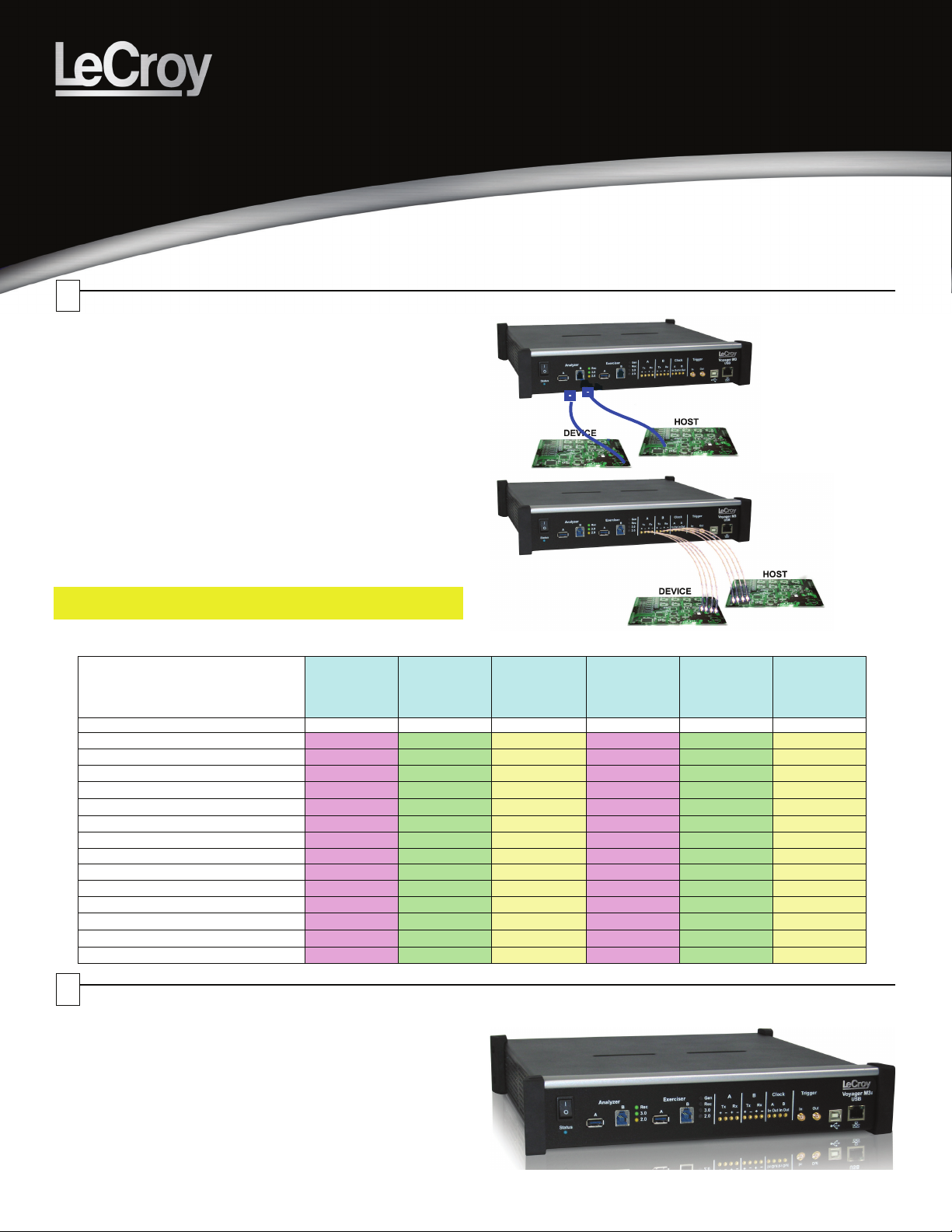
The system can monitor traffic between USB 2.0 links using
standard high-speed compliant cables.
If configured for USB 3.0 testing, the system supports monitoring
between SuperSpeed links using USB 3.0 cables or through direct
connection via MMCx-to-SMA coaxial cables.
Note: You must install the software before connecting the
Analyzer to the host machine for the first time.
The Voyager M3i models available are:
Feature Standard
Part number
USB 2.0 / USB 1.1 Recording
USB 3.0 / SuperSpeed Recording
Spool to Disk Recording
Standard Recording Memory
External Slow Clock Option
GbE Connection to host
Simultaneous USB 2.0 & 3.0 Recording
Sequential Triggering
Verification Script Engine (VSE)
Bus Utilization Graphs
USB 3.0 LTSSM View
Real-Time Statistics monitor (RTS)
Bus Utilization Graphs
Power Tracker™ Option
USB 2.0
Analyzer
USB-T0S2-V02-X USB-T0A2-V02-X USB-TZA2-V02-X USB-T0S3-V02-X USB-T0P3-V02-X USB-TZP3-V02-X
3 3 3 3 3 3
3 3 3 3 3 3
1GB 1GB 1GB 1GB 4GB 4GB
Advanced
USB 2.0
Analyzer
($) ($) ($) ($)
3 3 3 3
3 3 3 3
3 3 3 3
3 3 3 3
3 3 3 3
3 3 3 3
3 3 3 3
($) ($) ($) ($)
Advanced
USB 2.0
Analyzer with
Exerciser
Standard
USB 3.0
Analyzer
3 3 3
Pro
USB 3.0
Analyzer
3 3
Pro
USB 3.0
Analyzer with
Exerciser
2
Components
The Voyager M3i basic components are:
• Voyager M3i Protocol Analyzer/Exerciser System
• AC power cable
• USB cables (five)
• Installation CD-ROM, including documentation
• Micro to Standard USB adapter
• Mini to Standard USB adapter
• Quick Start Guide
Please see the USB Protocol Suite User Manual on the
installation CD for component specifications.
Page 2
3
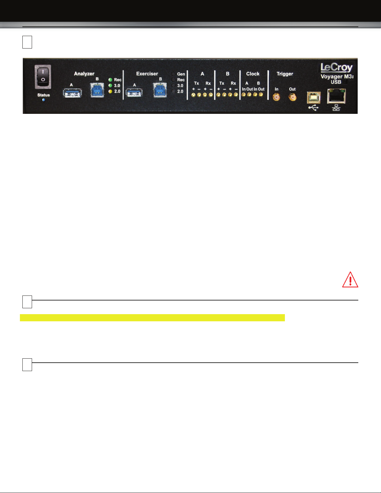
Description
The Analyzer has the following indicators and connectors:
Power Switch (0/1)
Status LED (blue if system successfully initializes)
(red if hardware failure)
(green while initializing)
Analyzer Ports A (downstream) and B (upstream)
Analyzer LEDs
Rec - Recording (red if recording enabled)
3.0 - USB 3.0 (green if traffic detected)
2.0 - USB 2.0 (yellow for Low and Full Speed)
(green for Hi Speed)
A (downstream) - MMCx plug connectors for interfacing
B (upstream) with USB 3.0 signals
Tx +- (Transmit pair)
Rx +- (Receive pair)
Clock A (downstream) - MMCx plug connectors for interfacing
Clock B (upstream) with external clock source or sink
In - Connects to an external reference clock.
Out - Provides reference clock output.
Trigger
In - SMA external trigger input.
Out - SMA external trigger output.
Exerciser Ports A (downstream) and B (upstream)
Exerciser LEDs
Gen- Generating (green if generating enabled)
Rec - Recording (red if recording enabled)
3.0 - USB 3.0 (green if traffic detected)
2.0 - USB 2.0 (yellow for Low and Full Speed)
(green for Hi Speed)
4
Installing the Software
Note: You must install the software before connecting the Analyzer to the host machine for the first time.
1. Insert the Installation CD into the CD drive on the host PC.
2. Select Install Software from the Installation CD and follow the on-screen installation instructions to install the application on the PC
hard disk.
5
Setting Up the Analyzer
To set up the Analyzer:
1. Connect the AC power cable to the rear of the Analyzer and
to a 100-volt to 240-volt, 50-Hz to 60-Hz, 100-W power outlet.
2. Connect the USB port to a USB port on the PC using the
LONG (6-foot/2-meter) USB cable.
3. Insert the Installation CD.
4. Turn on the power switch.
At power-on, the Analyzer initializes itself in approximately
ten seconds and performs an exhaustive self-diagnostic that
lasts about five seconds.
5. Click Next after you see the Add New Hardware Wizard
window.
USB - Type B connector for connection to host computer
ETHERNET - Gigabit Ethernet for connection to host computer
Note: The rear panel has only a power connector.
Warning: Do not open the Voyager M3i enclosure. No
operator serviceable parts are inside. Refer
servicing to LeCroy customer care.
®
6. Follow the Microsoft
instructions for the automatic installation of the Analyzer as a
USB device on your analyzing PC (the required USB files are
included on the Installation CD)
7. Click Finish when you see the message that says “Windows
has finished installing the software that your new hardware
requires” and the file lvoyager.inf has been installed in your
PC.
Note: Check Analyzer setup in the next section.
Windows® on-screen Plug-and-Play
Page 3

6
Starting the Application
To start the application, launch the LeCroy USB Protocol Suite program from the Start Menu:
Start > Programs > LeCroy > USB Protocol Suite > USB Protocol Suite
to open the main window.
You can use the software with or without the system connected to the host. Without the Analyzer, the program functions as a trace viewer
to view, analyze, and print trace files.
The first time you open the USB Protocol Suite application, confirm proper installation by selecting About from the Help menu to view the
Software Version, Firmware Version, BusEngine™ Version, and Unit Serial Number.
7
First USB Recording
After installing and launching the software, you can test the
system by performing the following steps:
1. Connect a USB cable to each of the two connectors on the
Analyzer module, then connect the other ends to the USB
device under test and USB host system.
2. Select Recording Options under Setup on the Menu Bar.
3. Select the General tab to display the following dialog box
showing factory default settings such as Snapshot and 16 MB
buffer size. For the first recording, you can leave these
settings unchanged
8. To save a current recording for future reference, select
Save As under File on the Menu Bar
OR
Click on the Tool Bar to display the standard Save As
screen.
Give the recording a unique name and save it to the
appropriate directory.
Trace View Features
After a moment, the recording terminates and the results display.
• The packet view display makes extensive use of color and
graphics to fully document the captured traffic.
• Packets are shown on separate rows, with their individual
fields both labeled and color coded.
• Packets are numbered (sequentially, as recorded),
time-stamped (with a resolution of 2 ns on 3.0 signalling), and
highlighted to show the transmitted speed (low-speed,
full-speed, high-speed, or superspeed).
• Display formats can be named and saved for later use.
• Data fields can be collapsed to occupy minimal space in the
display.
The display software can operate independently of the hardware
and so can function as a stand-alone Trace Viewer that may be
freely distributed
4. Click OK to activate the recording options you selected.
5. Turn on the USB devices that are to be tested and cause
them to generate USB traffic.
6. Click on the Tool Bar.
The system starts to record the USB traffic immediately. After
16 MB of traffic are recorded, the Analyzer uploads the data
and displays the packets in the trace window.
7. To terminate recording before the snapshot automatically
completes, click on the Tool Bar.
When the recording session is finished, the traffic is uploaded
from the Analyzer to the hard drive on your PC as a file
named data.usb or the name you assigned as the default
filename. While the file is being uploaded, you should see a
brown progress bar at the bottom of the screen. When the
bar disappears, it indicates that the data has been uploaded
to disk.
Page 4
8
Recording Traffic Generation with Analyzer
Recording Options
After installation, the system defaults to Snapshot recording. To change the default settings, refer to the “Recording Options” chapter of
the USB Protocol Suite User Manual.
Traffic Generation
Systems configured with the Voyager exerciser option can generate USB traffic and record the real response from the DUT.
Traffic Generation can also transmit known bad packets, providing an opportunity for engineers to observe how a device handles specific
adverse conditions.
To use Traffic Generation, refer to the “Traffic Generation” chapter of the USB Protocol Suite User Manual.
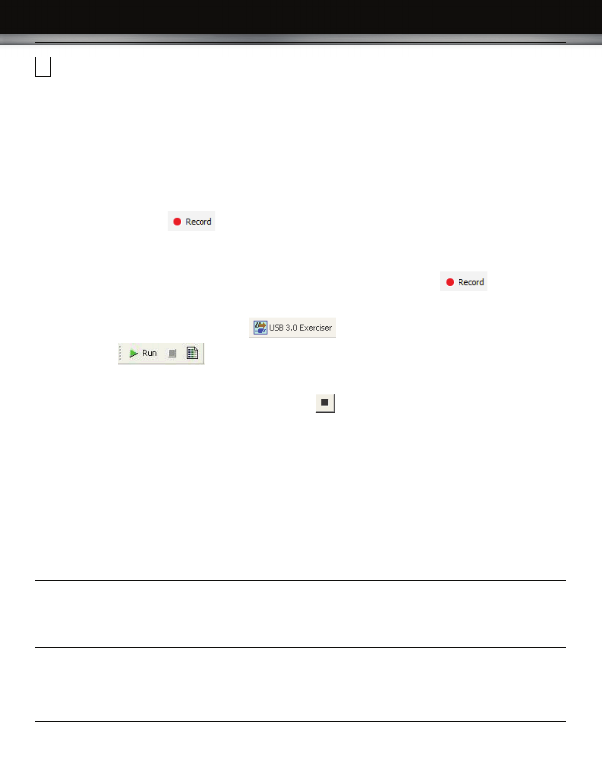
Start Recording
Click the Start Recording button on the Toolbar or select the Record > Start command.
Start Generation
Select Host Emulation or Device Emulation in the Recording/Generating section of the Misc. USB 3.0 tab of the Recording Options
dialog to cause the USB 3.0 Exerciser to continuously attempt to bring up a USB 3.0 link. Click Record on the toolbar and
connect the appropriate DUT. After 16 MB of traffic has been recorded, the trace automatically uploads from the analyzer to the PC, and
the software displays the captured packets.
Optionally, you can select the USB 3.0 Exerciser icon from the toolbar and open a sample generation file.
Click the Run button on the Toolbar or select the Generation > Run Scenario command.
Stop Recording
You may also choose to stop the recording by pressing the Stop button on the Tool bar or selecting the Record > Stop command.
The trace automatically uploads from the analyzer to the PC.
Interrupting the Upload Process: During upload, you can interrupt the upload process by pressing the Stop button to display the Abort
or Continue Uploading dialog box with the following options: Stop upload but keep the data that has been uploaded already, Stop upload
and discard (Flush) any data that has been uploaded, Continue upload, or Reupload part (Partial) of the recorded buffer.
Save the Trace
After upload finishes, the software saves the recorded traffic data in the LeCroy\USB Protocol Suite directory in a file named data.usb.
You can change the default directory and file name by clicking the Change Default Location button in the Trace Filename & Path
section of the General tab.
LeCroy Customer Support
Online Download
Periodically check the LeCroy Protocol Solutions Group web site for
software updates and other support related to this product. Software
updates are available to users with a current Maintenance Agreement.
Trademarks and Servicemarks
LeCroy Voyager, USB Protocol Suite, CATC Trace, and BusEngine are
trademarks of LeCroy Corporation.
Microsoft and Windows are registered trademarks of Microsoft Inc.
All other trademarks are property of their respective companies.
Mail: 3385 Scott Blvd., Santa Clara, CA 95054-3115
Web: http://www.lecroy.com/tm/Library/software/PSG
E-mail: psgsupport@lecroy.com
Tel: (800) 909-7112 (USA and Canada)
Tel: (408) 653-1260 (worldwide)
Fax: (408) 727-6622 (worldwide)
Changes
Product specifications are subject to change without notice.
LeCroy reserves the right to revise the information in this document
without notice or penalty.
Copyright © 2009 by LeCroy Corporation. All rights reserved. Part Number:
This document may be printed and reproduced without additional permission, but all copies should contain this copyright notice.
917547-00 Rev. A
 Loading...