

Page 1
Operator's
Manual
VirtualProbe
Software
Page 2

VirtualProbe Software Operator's Manual
© 2013 Teledyne LeCroy, Inc. All rights reserved.
Unauthorized duplication of Teledyne LeCroy documentation materials other than for internal sales and distribution purposes is strictly prohibited. However, clients are encouraged to distribute and duplicate Teledyne LeCroy documentation
for their own internal educational purposes.
VirtualProbe and Teledyne LeCroy are registered trademarks of Teledyne LeCroy, Inc. Windows is a registered trademark
of Microsoft Corporation. Other product or brand names are trademarks or requested trademarks of their respective
holders. Information in this publication supersedes all earlier versions. Specifications are subject to change without
notice.
921148 Rev A
May 2013
Page 3

Operator's Manual
TABLE OF CONTENTS
Virtual Probe Overview 2
Virtual Probe Process 2
Choose Your Mode of Operation 3
VirtualProbe, EyeDoctor-VPand EyeDoctor II 3
Compatible Models 3
Required Firmware 3
Modeling the Circuit 4
VirtualProbe Main Dialog 4
Setup Dialog 6
Block Setup Dialog 8
VirtualProbe (XTalk) Crosstalk Block 10
Touchstone File Format 12
921148 Rev A
1
Page 4
VirtualProbe Software
Virtual Probe Overview
The Teledyne LeCroy Virtual Probesoftware option lets you view waveforms as they would appear in circuit locations other than the probing point, and in circuit configurations different from the configuration
actually used for the measurement. By using Virtual Probe, you can understand the characteristics of signals where a physical probe cannot be placed, such as inside of a package or at the end of an interconnect that doesn't physically exist. You can choose to remove effects caused by elements such as
fixtures that will not be present when the device under test is used its final configuration, or add the
effects of a device that is to be included but for which only an S-parameter model exists.
VirtualProbe can be used in conjunction with the SDAIII-CompleteLinQfamily of serial data analysis tools,
or operated independently. It is compatible with SDAIII-CompleteLinQmulti-lane capabilities, integrating
seamlessly into the SDAIII-CompleteLinQframework flow diagram. When the oscilloscope is also outfitted with the Noise and Crosstalk measurement package (offered with SDAIII-CrossLinQ or SDAIII-CompleteLinQ), you can model the crosstalk across multiple lanes. Configuring and compiling the circuit
model is fast, and the software rapidly calculates the output waveforms.
Virtual Probe Process
The basic process for using Virtual Probe is:
l Create a model of the circuit to be analyzed using a simple user interface.
l For each block of the model, indicate whether or not the virtual probe output should include or
remove the effects of that block.
l For measurements taken with a differential probe, indicate the probe used to make the meas-
urement, so that the probe loading effects can be removed.
l Identify the position of the probe used to take the measurement.
2
921148 Rev A
Page 5

Operator's Manual
l Identify the position of a "virtual probe" that outputs the waveform that would be seen at the
selected position .
l When used in conjunction with SDAIII-CompleteLinQ serial data analysis packages, use the Vir-
tualProbe output as the source waveforms for equalization, eye, jitter, and noise measurements.
Choose Your Mode of Operation
VirtualProbe appears in the Analysis menu of the scope application. When used independent of SDAIIICompleteLinQ, choosing Analysis > VirtualProbe opens the VirtualProbe setup dialog, where you'll see
four, independent setups.
When used from within the SDAIII-CompleteLinQframework (EyeDoctor II required), choosing Analysis
>VirtualProbe opens a VirtualProbe dialog within the SDAIII-CompleteLinQ De-embed/Emulate dialog.
VirtualProbe, EyeDoctor-VPand EyeDoctor II
VirtualProbe is the next step in the evolution of Teledyne LeCroy's virtual probing capability that was
introduced in the EyeDoctor-VP package and was later included with the de-embed/emulate models in
EyeDoctor II. The core functionality of VirtualProbe is in part described in the EyeDoctor II section of this
Help system. EyeDoctor Irequired separate software for creating a system description file. EyeDoctor
IIincluded three choices for de-embedding and emulating 2 blocks (1 fixture and 1 channel). The current
VirtualProbe extends the EyeDoctor IIcapabilities to model up-to-6 blocks.
Compatible Models
VirtualProbe is compatible with WavePro/SDA/DDA 7 Zi/Zi-A, WaveMaster/SDA/DDA 8 Zi/Zi-A, LabMaster 9 Zi-A and 10 Zi series oscilloscopes.
Required Firmware
Your oscilloscope must be running firmware version 6.9.x.x or higher to support the VirtualProbe option.
Firmware upgrades are available from www.lecroy.com/support/downloads.
921148 Rev A
3
Page 6

VirtualProbe Software
Modeling the Circuit
VirtualProbe Main Dialog
The VirtualProbe main dialog is used to select an active setup/lane and configure the "blocks" in the circuit represented by it. It also displays summary information on and under each block that allows you to
quickly see how that block in the circuit is defined.
Before using this dialog to configure individual blocks, go to the VirtualProbe Setup Dialog to configure
the overall setup/lane.
NOTE: When used independently, you choose from among four setups (called SetupA, SetupB, etc.) to
configure. When used with SDAIII-CompleteLinQ, you select a Lane (e.g., Lane1) to configure.
Independent Use
The VirtualProbe dialog takes on a slightly different appearance depending on whether it is being used
from within the SDAIII-CompleteLinQframework or independently. These controls appear when VirtualProbe is used independent of SDAIII-CompleteLinQ.
SetupA...SetupD buttons - Touch to select a setup. A Setup tab and individual block tabs for the currently selected setup will be displayed (e.g. when SetupA is selected, tabs for SetupA, blocks A1, A2, etc.
are displayed)
Setup Status LED - An LED next to each setup button displays the current status of the setup.
l Red: Error in setup. Check the setup for any inconsistency in the Num Ports, Input Type, or the
block setup for undefined files or touchstone files with incorrect port count.
l Yellow:Apply needed; touch the Apply button when you are finished making changes to the setup
l Green:Compilation successful.
l Dimmed: The output of the setup is unused.
View Output (one per setup) - Touch to display virtually probed waveform at the position specified by
the VProbe checkbox. The waveform name is VPOutX, where "X"is A, B, C or D, corresponding to the
setup chosen
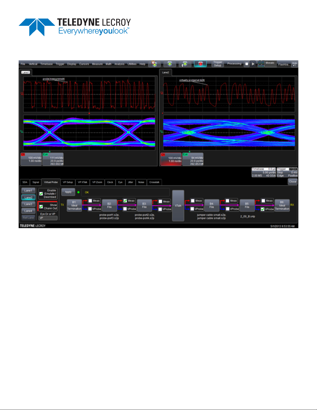
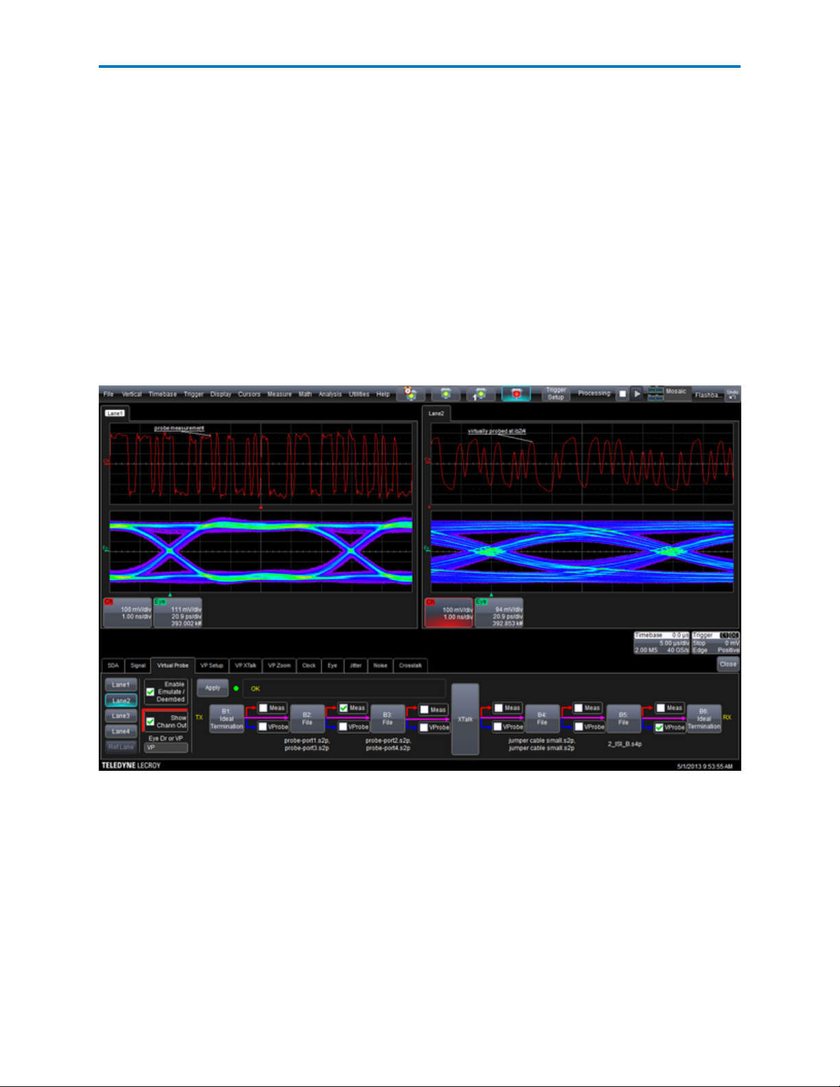
SDAIII-CompleteLinQ Use
These controls appear when VirtualProbe is used in conjunction with SDAIII-CompleteLinQ.
Lane1...Lane4 buttons - Touch to select a lane to setup. A VPSetup tab will be displayed that contains
the setup for the selected lane.
Show Chann Out checkbox - Touch to display the virtually probed waveform at the position specified by
the VProbe checkbox. The waveform name is "Ch."
4
921148 Rev A
Page 7

Operator's Manual
Status LED - An LEDnext to the Apply button indicates the status of the VirtualProbe setup for the
selected lane.
Setup Status LED - An LED next to each setup button displays the current status of the setup.
l Red: Error in setup. Check the setup for any inconsistency in the Num Ports, Input Type, or the
block setup for undefined files or touchstone files with incorrect port count.
l Yellow:Apply needed; touch the Apply button when you are finished making changes to the setup
l Green:Compilation successful.
l Dimmed: The output of the setup is unused.
Common
These controls appear in all instances of VirtualProbe.
Apply button - Touch to build the system description for the circuit, and to compile it. When the Crosstalk package is present. When the Xtalk box is available, touching Apply compiles all setups or lanes
together; without, only the selected lane is compiled. While compiling, the message "Compiling"is displayed in the lower-right corner of the application. The result of the compilation is displayed in the adjacent box. Success is indicated as "Compilation Succeeded".
Block Definition buttons (e.g. A1...A6) - Touch to open the dialog for configuring the selected block. The
first and last blocks are dedicated as transmitter (data source) and receiver blocks (data sink). All blocks in
between may be configured as circuit elements that connect the transmitter to the receiver. The button
will show the action being taken by the block.
XTalk button - Touch to open the dialog for configuring the Xtalk block. This block is used to model crosstalk between the lanes. See __for configuration details.
Meas checkboxes - These checkboxes are visible when the Input Type in the Setup dialog is set to
"Probe." Check the Meas checkbox that corresponds to the position of the differential probe where the
measurement is being taken. (When the Input Type is set to "Channel," the measurement position is
assumed to be at the receiver, meaning that the oscilloscope is acting as the receiver for the channel. If
you change the location of the probe by checking a different Meas checkbox, touch Apply to re-compile
the model.
VProbe checkboxes - Check the VProbe checkbox corresponding to the position where you would like to
locate the virtual probe. If you change the location of the "probe" by checking a different VProbe checkbox, touch Apply to re-compile the model.
921148 Rev A
5
Page 8

VirtualProbe Software
Setup Dialog
The Virtual Probe Setup dialog configures the overall settings for the circuit represented by the selected
setup or lane.
Source Setup
The settings in the Source Setup section of the dialog define the overall topology of the circuit and how it
connects to the oscilloscope taking the measurement.
Num Ports field - Enter 2 or 4 to define whether the circuit is connecting a single-ended or differential
lane between the transmitter and receiver. When choosing 2, for a single-ended lane, each block in the
circuit is a 2-port network, with one input and one output. When choosing 4, for a differential lane, each
block is a 4-port network, with two inputs (+and -) and two outputs. The selection for Num Ports needs
to be consistent with the data source setup. Note that when using Virtual Probe from within the SDAIIICompleteLinQframework, the data sources are configured in the Signal Input dialog for the selected
lane.
Input Type field - When using a differential probe, select "Probe". When using cabled oscilloscope
inputs, select "Channel". When using Channel, the measurement point is assumed to be at the receiver.
Remove Probe Loading checkbox - Check to use the probe loading model for the selected probe to deembed the probe from the measurement. This checkbox is enabled when InputType = Probe.
Probe Model selector - Select the model of the differential probe to used for the measurement. This
selector is enabled when InputType = Probe.
INDEPENDENT USE
These controls appear in the Source Setup section when VirtualProbe is used independent of SDAIII-CompleteLinQ:
Data Source + :Select a source waveform. When using a differential probe, this will be the oscilloscope
channel that the probe is connected to. When using Input Type = Channel, Num Ports = 4, this is the oscilloscope channel receiving the (+)side of the differential pair. When using "Channel"and NumPorts = 2,
then there is only one data source; Data Source + is used in this scenario. Note that when using Virtual
Probe from within the SDAIII-CompleteLinQframework, the data sources are configured in the Signal
Input dialog for the selected lane.
Data Source - : When Num Ports = 4AND Input Type = Channel (i.e. the circuit is transmitting a differential
pair being received by two oscilloscope channels), then Data Source - becomes active. Choose the source
waveform for the (-) side of the differential pair.
Users may configure any waveforms for the data sources, and not just Cx waveforms.
6
921148 Rev A
Page 9

Operator's Manual
NOTE:there is no need to configure a math function to be the difference between two inputs when using
VirtualProbe.
SDAIII-COMPLETELINQUSE
When using VirtualProbe from within the SDAIII-CompleteLinQ framework, the data source for the active
lane is configured on the SDAIII-CompleteLinQ Signal dialog.
Measurement Filter Section
The measurement filter section of the Setup dialog configures elements that determine the bandwidth
limit of the filter and the maximum gain.
AutoBWLimit checkbox - Check to automatically determine the best setting for BW limit. The algorithm
uses the Max Boost value to determine the BW value to use.
Max Boost field - Select a value for limiting the maximum boost to apply when de-embedding a block. A
vale that is too high can boost noise and lead to undesirable results.
Filter Order field - The filter utilized for handling the measurement bandwidth is generally a high order
filter. It is implemented as a filter that has a magnitude response given by a Butterworth filter of a given
order. The phase response is always linear. The default value is 20, which is a very high order filter, but for
sharper cutoff, higher orders can be used. A filter rolls off at 20 dB/decade (or 6 dB/octave) more for
every increase in filter order.
BW Limit field -Set a value to limit the bandwidth of the filter.
Applying the Setting
After configuring the general circuit and individual blocks, return to either the Setup or VirtualProbe
dialog and touch the Apply button to apply the settings.
Apply button - Touch to build the system description for the circuit and to compile it. When the Xtalk
box is available, touching Apply compiles all setups or lanes together; without, only the selected lane is
compiled. While compiling, the message "Compiling"is displayed in the lower-right corner of the application. The result of the compilation is displayed in the adjacent box. Success is indicated as "OK." If the
oscilloscope still needs an input waveform in order to build the filter, you will see a message to that
effect.
Setup Status LED - An LED next to each setup button displays the current status of the setup:
l Red: Error in setup. Check the setup for any inconsistency in the Num Ports, Input Type, or the
block setup for undefined files or touchstone files with incorrect port count.
l Yellow:Apply needed; touch the Apply button when you are finished making changes to the setup
l Green:Compilation successful.
l Dimmed: The output of the setup is unused.
921148 Rev A
7
Page 10

VirtualProbe Software
Block Setup Dialog
The Block Setup dialog is displayed when you touch a Block definition button. It is used to configure the
corresponding block in the circuit.
Block Action Checkboxes
When a block is configured for something other than "Ideal Thru," the left-side of the dialog includes a
set of checkboxes that determine how the circuit element defined by the block is handled. There are
effectively three actions defined by these checkboxes:
Remove effects caused by block checkbox - check this when you want the electrical behavior of the circuit element to be removed from the signal. This is usually referred to as "De-embedding". Use this setting when wanting to remove the effects of fixtures or interconnects that would otherwise not be in the
path between the transmitter and receiver.
Include effects caused by block checkbox - When not seeking to remove the effects caused by a block,
check "Include effects caused by block." Checking this box enables two more selections that will determine the block action:
Block is present at time of measurement checkbox - check this when the element was in
the circuit when the measurement was taken, and you wish to include its effects in the output of the virtual probe. That is, you are not seeking to either de-embed or emulate: the
block is a real circuit element, and its effects are to be included in the VirtualProbe output.
Block is NOT present at time of measurement checkbox - check this when wanting to
include the effects of a "virtual channel." This is often referred to as "emulating a channel,"
where the S-parameters of a channel are used to build a transfer function that models the
reflections and loss characterized by the S-parameters. Atypical use-case for this selection
is when you wish to understand how a signal would look if the path between the transmitter and receiver were to be extended by an interconnect that does physically exist, and
for which you only have an S-parameter model.
Block Type Selector
Ideal Thru - This is the default state. Use this setting when the block is unused or as a placeholder
between other blocks.
Ideal Termination - This choice is only present for the outermost blocks, which correspond to the transmitter and receiver, and sets the termination to 50 ohm.
8
921148 Rev A
Page 11

Operator's Manual
Transmission Line - Select to use a lossless transmission line modeled by its delay and characteristic
impedance.
Touchstone File - Select to use S-parameters to represent the block. The Touchstone file should follow
the Touchstone 1 format, and should also meet requirements described in Touchstone File Format.
When you select Touchstone File, the additional settings described below are enabled.
Touchstone File Block Type
If you choose to define a block by importing a Touchstone file of S-parameters, these additional controls
will appear:
NumFiles - This selector is visible when the setup/lane is configure for 4 ports. See Setup Dialog for port
setup information. Choose "1"to use a 4-port touchstone file, or "2" to use two 2-port touchstone files.
Using two 2-port files is typically done when looking to describe the block using two transmission lines
(such as cables) between which there is no meaningful crosstalk, such that using two 2-port S-parameters
files is an accurate model for the block.
Format - This selector is visible when the setup/lane is configure for 4 ports. (See Setup Dialog for port
setup information). In the unusually circumstance in which the S-parameters where saved in a mixedmode format, select "Mixed mode".
NOTE: The Touchstone 1 format is not designed for mixed-mode S-parameters, and using Touchstone
1.0 to store mixed-mode S-parameters is NOTrecommended. While it is certainly important to understand mixed-mode characteristics of differential interconnects, Teledyne LeCroy highly recommends saving your S-parameters in single-ended format in order to prevent any future confusion.
Touchstone File Port Mapping - The diagram in this section of the dialog will adapt to the settings for
NumPorts, NumFiles, and Format. Configure the port number selectors in the diagram to correctly map
the port numbers in the S-parameters file(s) to the input and output ports of the block.
NOTE: if the VirtualProbe output is extremely distorted, then it is possible that the ports were not
assigned correctly.
Mapping for four-port network specified in one file.
921148 Rev A
Mapping for four-port network specified in two files.
9
Page 12

VirtualProbe Software
Mapping for two-port network specified in two files.
VirtualProbe (XTalk) Crosstalk Block
When the Crosstalk package is present on the oscilloscope, the main VirtualProbe dialog will include the
XTalk block. The block is used to define the S-parameter Touchstone file and port assignments. By using
the XTalk block—and in doing so, including a model of the crosstalk between lanes—you can create a
more accurate model of the circuit and obtain better VirtualProbe results.
The initial implentation of the XTalk block includes the following requirements. If the requirements aren't
met, then warning triangles are shown in the dialog, along with a message in the VirtualProbe Status indicator.
l The VPSetup should be NumPorts=4, InputType=Channel
l The Signal Input configuration should match the above requirement, meaning that two data
sources should be provided.
XTalk Dialog Elements
The XTalk dialog includes configuration elements in common with other block types.
BLOCK ACTION
When a block is configured for something other than "Ideal Thru," the left-side of the dialog includes a
set of checkboxes that determine how the circuit element defined by the block is handled. There are
effectively three actions defined by these checkboxes:
Remove effects caused by block checkbox - check this when you want the electrical behavior of the circuit element to be removed from the signal. This is usually referred to as "De-embedding". Use this setting when wanting to remove the effects of fixtures or interconnects that would otherwise not be in the
path between the transmitter and receiver.
Include effects caused by block checkbox - When not seeking to remove the effects caused by a block,
check "Include effects caused by block." Checking this box enables two more selections that will determine the block action:
Block is present at time of measurement checkbox - check this when the element was in
the circuit when the measurement was taken, and you wish to include its effects in the output of the virtual probe. That is, you are not seeking to either de-embed or emulate: the
block is a real circuit element, and its effects are to be included in the VirtualProbe output.
Block is NOT present at time of measurement checkbox - check this when wanting to
include the effects of a "virtual channel." This is often referred to as "emulating a channel,"
where the S-parameters of a channel are used to build a transfer function that models the
reflections and loss characterized by the S-parameters. Atypical use-case for this selection
10
921148 Rev A
Page 13

Operator's Manual
is when you wish to understand how a signal would look if the path between the transmitter and receiver were to be extended by an interconnect that does physically exist, and
for which you only have an S-parameter model.
CONFIGURATION
The Config selector allows the user to from several topologies for the XTalk block:
1xS8P - Select to use a single 8-port S-parameter model
1xS12P -Select to use a single 12-port S-parameter model
2xS8P - Select to use two 8-port S-parameter models.
The dialog will adapt based on the config selected, showing a network(s) with the number of ports corresponding to the selection. For example, selecting 1xS12P shows a 12-port network; selecting 2xS8P
shows two 8-port networks (16 ports total).
PORTS ASSIGNMENTS
On the left side of the Touchstone File Port Mapping section, select the S-parameter port number that
maps to the signal flow for each lane. Lane numbers go from top to bottom, and, since each lane is differential in the XTalk model, each lane should map to a (+) and (-) port. On the right side, select the ports
that correspond as THRUs for the input ports.
APPLY SETTINGS
After completing XTalk configuration, switch to the VirtualProbe or any VPSetup dialog and click Apply.
The system description is compiled. When XTalk is active, there is only one system description to compile, which includes all lanes.
921148 Rev A
11
Page 14

VirtualProbe Software
Warnings and Error Messages
If all lanes are not setup as 4 port, Channel in the VPSetup dialogs for each lane, then a message will be
displayed. For example:
Warning triangles may also be displayed in the XTalk dialog when an error situation exist. Touch the triangle to call up a dialog that explains the error.
Touchstone File Format
Touchstone is a file format used for specifying S-parameters. It is a standard that is commonly adopted
by vector network analyzers (VNAs), time-domain network analyzers (TDNA) and EDA tools such as microwave simulators.
Specification
VirtualProbe requires that Touchstone files meet the following specification:
l The extension must be in the form .s[N]p where [N] corresponds to the number of ports in the
device. For example, a two port S-parameter file has an extension ".s2p".
l Lines cannot be longer than 2000 characters.
l Lines beginning with ! are comment lines. Comments must be at the front of the file. No com-
ments are allowed once the frequencies and S-parameter values start.
l There should be at least one line that begins with ‘#'. This line is a line that contains tokens that
help interpret the S-parameters. Valid tokens are:
l Hz – frequencies are in Hz.
l MHz – frequencies are in MHz.
l GHz – frequencies are in GHz.
l MA – S-parameters are in magnitude/angle form where the magnitudes are true mag-
nitudes and the angle is in degrees.
l RI – S-parameters are in real/imaginary form.
l DB – S-parameters are in magnitude/angle form where the magnitude is in decibels and the
angle is in degrees.
l If the above tokens are not found, the frequencies are assumed to be in MHz, and the S-param-
eters are assumed to be in magnitude/angle form.
l The S-parameters for each frequency are assumed to be listed as:
[frequency] (S11) (S12) …(S1[N])(S21) (S22) … (S2[N]) … (S[N]1) (S[N]2) … (S[N][N])
where N is the number of ports dictated by the file extension, except for two-port S-parameters
which are assumed to be listed as [frequency] (S11) (S21) (S12) (S22) according to the standard.
l All S-parameters are assumed to be 50 Ohm. In S-parameter files, on the line beginning with ‘#',
usually there is a token pair: R [Z0] where [Z0] is the characteristic impedance. We assume Z0 is 50
and ignore these tokens.
12
921148 Rev A
Page 15

Operator's Manual
l All frequencies are assumed to go from the first frequency listed to the last frequency listed with
constant frequency spacing.
S-parameter File Interpretation and Usage
S-parameters provided to the virtual probe will tend to have various frequency scales, differing in both
resolution (frequency spacing) and range (start frequency and end frequency). The VirtualProbe component will resample all S-parameter sets onto a new frequency scale dictated by the system sample rate
(half the sample rate will be the last frequency) and the time length (see Time Length) – where the time
length dictates the new frequency resolution. In performing this resampling, it is important to understand that the resolution may be higher or lower than the original resolution and that the frequency
range may require extrapolation of points. When the frequency range is higher than that provided in the
S-parameter data (i.e. the S-parameters are not provided to half the system sample rate), then the Sparameter data will be set to zero at these extra required data points. Furthermore, most S-parameter
data does not go to DC, because VNAs don't measure data to DC, and therefore the DC response is also
extrapolated by setting the low frequency points equal to the first frequency provided in the S-parameter
data.
What this means is that it is helpful to follow some simple rules that will maximize the effectiveness of the
virtual probe.
l Take S-parameter data as low in frequency as the VNA allows to minimize DC extrapolation errors.
l Take S-parameter data up to one half of the system sample rate. In other words, if you are going
to supply waveforms to the virtual probe at 40 GS/s, it is good to provide data up to 20 GHz. Otherwise, if the frequency content of the signal provided to the system is much lower, then it is unnecessary to sample at a high sample rate anyway.
l Take S-parameter data with sufficient frequency resolution. The resolution that needs to be pro-
vided depends on the electrical lengths of the circuit elements involved. In other words, if you
have a cable that is 5 ns long, and there are reflections going on in the system, then taking data at
maybe one tenth the minimum frequency resolution of 1/5 ns = 200 MHz (like 20 MHz) is a good
idea. Said differently, in a more practical manner, if there are lots of bumps and wiggles in the Sparameters that are narrow in frequency, then you will need to measure S-parameter data with an
appropriate frequency resolution to capture these bumps and wiggles. Usually the narrowness of
the bumps and wiggles becomes smaller when the electrical lengths of circuit elements becomes
longer.
921148 Rev A
13
Page 16

 Loading...