

Page 1
PROTOCOL SOLUTIONS GROUP
3385 SCOTT BLVD
SANTA CLARA, CA 95054
USB Protocol Suite™
User Manual
LeCroy
Manual Version 4.21
Advisor T3™ USB Advisor™
USBTracer/Trainer™
Voyager M3™
USBMobile HS USBMobile T2
For Software Version 4.21
June 2011
Page 2

USB Protocol Suite User Manual
Document Disclaimer
The information in this document has been carefully checked and is believed to be
reliable. However, no responsibility can be assumed for inaccuracies that may not have
been detected. LeCroy reserves the right to revise the information in this document
without notice or penalty.
Changes or Modifications
Any change or modification not expressly approved by LeCroy voids the user’s authority
to operate this equipment.
Trademarks and Servicemarks
CATC, LeCroy Voyager, Voyager ReadyLink, USB Protocol Suite, USB Advisor,
Advisor T3, USB Chief, USB Inspector, USB Detective, USB Tracer/Trainer, and
BusEngine are trademarks of LeCroy.
Microsoft and Windows are registered trademarks and Windows Vista is a trademark of
Microsoft Inc.
Intel is a registered trademark, and Core is a trademark, of Intel Corporation.
All other trademarks are property of their respective companies.
Copyright
Copyright © 2011, LeCroy Corporation. All Rights Reserved. This document may be
printed and reproduced without additional permission, but all copies should contain this
copyright notice.
FCC Conformance Statement
This equipment has been tested and found to comply with the limits for a Class A digital
device, pursuant to Part 15 of the FCC Rules. These limits are designed to provide
reasonable protection against harmful interference when the equipment is operated in a
commercial environment. This equipment generates, uses, and can radiate radio
frequency energy and, if not installed and used in accordance with the instruction manual,
may cause harmful interference to radio communications. Operation of this equipment in
a residential area is likely to cause harmful interference in which case the user is required
to correct the interference at his own expense. The end user of this product should be
aware that any changes or modifications made to this equipment without the approval of
LeCroy could result in the product not meeting the Class A limits, in which case the FCC
could void the user's authority to operate the equipment.
EU Conformance Statement
This equipment complies with the EMC Directive 89/336/EEC and the Low Voltage
Directive 73/23/EEC, and their associated amendments for Class A Information
Technology Equipment. It has been tested and found to comply with EN55022:1998
Class A (EN61000-3-2:1998, EN61000-3-3:1995) and EN55024:1998
(EN61000-4-2:1998, EN61000-4-3:1996, EN61000-4-4:1996, EN61000-4-5:1996,
EN61000-4-6:1997, EN61000-4-11:1998), and EN60950:1999. In a domestic
environment this product may cause radio interference in which case the user may be
required to take adequate measures.
LeCroy Corporation
Page 3

USB Protocol Suite User Manual
This electronic product is subject to
disposal and recycling regulations that
vary by country and region. Many
countries prohibit the disposal of
waste electronic equipment in
standard waste receptacles.
For more information about proper
disposal and recycling of your LeCroy
product, please visit
www.lecroy.com/recycle.
WEEE Program
LeCroy Corporation
Page 4

USB Protocol Suite User Manual
LeCroy Corporation
Page 5

USB Protocol Suite User Manual
TABLE OF CONTENTS
Chapter 1 Overview. . . . . . . . . . . . . . . . . . . . . . . . . . . . . . 1
1.1 Common Features . . . . . . . . . . . . . . . . . . . . . . . . . . . . . . . . . . . . . 1
1.1.1 Graphical Bus Traffic Display . . . . . . . . . . . . . . . . . . . . . . . . 1
1.1.2 Accurate Time Measurement (Voyager, Advisor T3) . . . . . . 2
1.1.3 CrossSync Control Panel (Voyager, Advisor T3) . . . . . . . . . 2
1.1.4 Comprehensive Error Detection and Analysis . . . . . . . . . . . 2
1.1.5 Real-Time Event Triggering and Capture Filtering . . . . . . . . 3
1.1.6 Advanced Event Counting and Sequencing . . . . . . . . . . . . . 3
1.1.7 BusEngine Technology . . . . . . . . . . . . . . . . . . . . . . . . . . . . . 3
1.2 Voyager M3 Analyzer . . . . . . . . . . . . . . . . . . . . . . . . . . . . . . . . . . . 4
1.2.1 Voyager M3 General Description . . . . . . . . . . . . . . . . . . . . . 6
1.2.2 Voyager M3 Features . . . . . . . . . . . . . . . . . . . . . . . . . . . . . . 7
1.2.3 Hi-Speed Slow Clock . . . . . . . . . . . . . . . . . . . . . . . . . . . . . . 9
1.2.4 Traffic Generation . . . . . . . . . . . . . . . . . . . . . . . . . . . . . . . . 10
1.2.5 Notes on LFPS Signals . . . . . . . . . . . . . . . . . . . . . . . . . . . . 11
1.3 USBTracer/Trainer . . . . . . . . . . . . . . . . . . . . . . . . . . . . . . . . . . . . 12
1.3.1 USBTracer/Trainer General Description . . . . . . . . . . . . . . . 12
1.3.2 USBTracer/Trainer Features. . . . . . . . . . . . . . . . . . . . . . . . 14
1.3.3 Traffic Generation . . . . . . . . . . . . . . . . . . . . . . . . . . . . . . . . 16
1.3.4 Hi-Speed Slow Clock . . . . . . . . . . . . . . . . . . . . . . . . . . . . . 16
1.4 Advisor . . . . . . . . . . . . . . . . . . . . . . . . . . . . . . . . . . . . . . . . . . . . . 17
1.4.1 Advisor Features . . . . . . . . . . . . . . . . . . . . . . . . . . . . . . . . . 17
1.5 Advisor T3 . . . . . . . . . . . . . . . . . . . . . . . . . . . . . . . . . . . . . . . . . . 20
1.5.1 Advisor T3 General Description . . . . . . . . . . . . . . . . . . . . . 21
1.5.2 Advisor T3 Features . . . . . . . . . . . . . . . . . . . . . . . . . . . . . . 22
1.6 USBMobile T2 . . . . . . . . . . . . . . . . . . . . . . . . . . . . . . . . . . . . . . . 25
1.6.1 Features . . . . . . . . . . . . . . . . . . . . . . . . . . . . . . . . . . . . . . . 26
1.7 USBMobile HS . . . . . . . . . . . . . . . . . . . . . . . . . . . . . . . . . . . . . . . 28
Chapter 2 General Description. . . . . . . . . . . . . . . . . . . . 29
2.1 Voyager M3 System Components/Packing List . . . . . . . . . . . . . . 29
2.2 Voyager M3 PC Requirements. . . . . . . . . . . . . . . . . . . . . . . . . . . 29
2.3 Voyager M3 Analyzer . . . . . . . . . . . . . . . . . . . . . . . . . . . . . . . . . . 29
2.4 Voyager M3 Specifications . . . . . . . . . . . . . . . . . . . . . . . . . . . . . . 32
2.4.1 Power Requirements. . . . . . . . . . . . . . . . . . . . . . . . . . . . . . 32
2.4.2 Environmental Conditions . . . . . . . . . . . . . . . . . . . . . . . . . . 32
2.4.3 Probing Characteristics . . . . . . . . . . . . . . . . . . . . . . . . . . . . 32
2.4.4 Switches . . . . . . . . . . . . . . . . . . . . . . . . . . . . . . . . . . . . . . . 32
2.4.5 Recording Memory Size . . . . . . . . . . . . . . . . . . . . . . . . . . . 32
2.5 USBTracer/Trainer System Components . . . . . . . . . . . . . . . . . . . 33
2.6 USBTracer/Trainer Analyzer PC Requirements . . . . . . . . . . . . . . 33
2.7 The Installed USBTracer Unit. . . . . . . . . . . . . . . . . . . . . . . . . . . . 33
2.7.1 LED and Button Descriptions . . . . . . . . . . . . . . . . . . . . . . . 34
2.7.2 Back Panel . . . . . . . . . . . . . . . . . . . . . . . . . . . . . . . . . . . . . 34
2.8 USBTracer System Setup . . . . . . . . . . . . . . . . . . . . . . . . . . . . . . 35
LeCroy Corporation v
Page 6

USB Protocol Suite User Manual
2.9 USBTracer/Trainer Specifications. . . . . . . . . . . . . . . . . . . . . . . . . 35
2.9.1 Package . . . . . . . . . . . . . . . . . . . . . . . . . . . . . . . . . . . . . . . 35
2.9.2 Connectors . . . . . . . . . . . . . . . . . . . . . . . . . . . . . . . . . . . . . 35
2.9.3 Weight . . . . . . . . . . . . . . . . . . . . . . . . . . . . . . . . . . . . . . . . 35
2.9.4 Power Requirements. . . . . . . . . . . . . . . . . . . . . . . . . . . . . . 35
2.9.5 Environmental Conditions . . . . . . . . . . . . . . . . . . . . . . . . . 36
2.9.6 Probing Characteristics . . . . . . . . . . . . . . . . . . . . . . . . . . . 36
2.9.7 Switches . . . . . . . . . . . . . . . . . . . . . . . . . . . . . . . . . . . . . . . 36
2.9.8 Indicators (LEDs) . . . . . . . . . . . . . . . . . . . . . . . . . . . . . . . . 36
2.9.9 Recording Memory Size . . . . . . . . . . . . . . . . . . . . . . . . . . . 37
2.10 USBTracer/Trainer External Interface Breakout Board . . . . . . . 38
2.10.1 Pin-Outs for the Data In/Out Connector . . . . . . . . . . . . . . 39
2.10.2 Prototype Rework Area . . . . . . . . . . . . . . . . . . . . . . . . . . . 39
2.11 Advisor . . . . . . . . . . . . . . . . . . . . . . . . . . . . . . . . . . . . . . . . . . . . 40
2.12 Advisor PC Requirements . . . . . . . . . . . . . . . . . . . . . . . . . . . . . 40
2.13 Advisor System Components/Packing List. . . . . . . . . . . . . . . . . 40
2.14 Advisor Stand-Alone Unit . . . . . . . . . . . . . . . . . . . . . . . . . . . . . . 41
2.15 Advisor System Setup . . . . . . . . . . . . . . . . . . . . . . . . . . . . . . . . 43
2.16 Advisor Specifications. . . . . . . . . . . . . . . . . . . . . . . . . . . . . . . . . 44
2.16.1 Package . . . . . . . . . . . . . . . . . . . . . . . . . . . . . . . . . . . . . . 44
2.16.2 Power Requirements. . . . . . . . . . . . . . . . . . . . . . . . . . . . . 44
2.16.3 Environmental Conditions . . . . . . . . . . . . . . . . . . . . . . . . 44
2.16.4 Switches . . . . . . . . . . . . . . . . . . . . . . . . . . . . . . . . . . . . . . 44
2.16.5 LEDs . . . . . . . . . . . . . . . . . . . . . . . . . . . . . . . . . . . . . . . . 44
2.16.6 Recording Memory Size . . . . . . . . . . . . . . . . . . . . . . . . . . 44
2.17 Advisor External Interface Breakout Board . . . . . . . . . . . . . . . . 45
2.17.1 Pin-Outs for the Data In/Out Connector . . . . . . . . . . . . . . 46
2.17.2 Prototype Rework Area . . . . . . . . . . . . . . . . . . . . . . . . . . . 46
2.17.3 PC Connection . . . . . . . . . . . . . . . . . . . . . . . . . . . . . . . . . 46
2.18 Advisor T3 . . . . . . . . . . . . . . . . . . . . . . . . . . . . . . . . . . . . . . . . . 47
2.18.1 Components . . . . . . . . . . . . . . . . . . . . . . . . . . . . . . . . . . . 47
2.18.2 Front Panel . . . . . . . . . . . . . . . . . . . . . . . . . . . . . . . . . . . . 47
2.18.3 Rear Panel . . . . . . . . . . . . . . . . . . . . . . . . . . . . . . . . . . . . 48
2.18.4 Advisor T3 System Setup . . . . . . . . . . . . . . . . . . . . . . . . . 49
2.19 USBMobile T2 and USBMobile HS . . . . . . . . . . . . . . . . . . . . . . 50
2.19.1 Setup. . . . . . . . . . . . . . . . . . . . . . . . . . . . . . . . . . . . . . . . . 50
Chapter 3 Installation . . . . . . . . . . . . . . . . . . . . . . . . . . . 51
3.1 Installing the Analyzer Software on the PC . . . . . . . . . . . . . . . . . 51
3.2 Setting Up the Analyzer - USB Connection . . . . . . . . . . . . . . . . . 51
3.3 Setting Up the Analyzer - Ethernet Connection . . . . . . . . . . . . . . 52
3.4 Cascading with CATC SYNC Expansion Card. . . . . . . . . . . . . . . 53
3.4.1 Removing Expansion Cards . . . . . . . . . . . . . . . . . . . . . . . . 53
3.5 Application Startup . . . . . . . . . . . . . . . . . . . . . . . . . . . . . . . . . . . . 56
3.5.1 Confirm Proper Hardware Installation and USB or
Ethernet Connection . . . . . . . . . . . . . . . . . . . . . . . . . . . . . . 56
3.5.2 Analyzer Devices . . . . . . . . . . . . . . . . . . . . . . . . . . . . . . . . 57
3.5.3 IP Settings (Voyager only) . . . . . . . . . . . . . . . . . . . . . . . . . 58
3.5.4 Analyzer Network . . . . . . . . . . . . . . . . . . . . . . . . . . . . . . . . 61
3.5.5 USB 3.0 Device/Host Signal Parameters . . . . . . . . . . . . . . 62
3.5.6 USB 3.0 Cabling and Signal Integrity . . . . . . . . . . . . . . . . . 64
vi LeCroy Corporation
Page 7

USB Protocol Suite User Manual
3.6 Your First USB Recording . . . . . . . . . . . . . . . . . . . . . . . . . . . . . . 65
3.6.1 Trace View Features . . . . . . . . . . . . . . . . . . . . . . . . . . . . . . 67
3.7 Notes on Vista and Windows 7 Directory Protections . . . . . . . . . 68
3.7.1 User Data File Paths. . . . . . . . . . . . . . . . . . . . . . . . . . . . . . 68
Chapter 4 Software Overview. . . . . . . . . . . . . . . . . . . . . 69
4.1 Starting the Program. . . . . . . . . . . . . . . . . . . . . . . . . . . . . . . . . . . 69
4.2 The Main Display Window . . . . . . . . . . . . . . . . . . . . . . . . . . . . . . 70
4.2.1 Exports to .CSV. . . . . . . . . . . . . . . . . . . . . . . . . . . . . . . . . . 76
4.2.2 Exporting to USB 2.0 Generation Files (.utg files) . . . . . . . 77
4.3 Tool Bar . . . . . . . . . . . . . . . . . . . . . . . . . . . . . . . . . . . . . . . . . . . . 78
4.3.1 Files, Searches, and Options . . . . . . . . . . . . . . . . . . . . . . . 78
4.3.2 Zoom and Wrap . . . . . . . . . . . . . . . . . . . . . . . . . . . . . . . . . 78
4.3.3 Miscellaneous . . . . . . . . . . . . . . . . . . . . . . . . . . . . . . . . . . . 79
4.3.4 Analysis (Reports) . . . . . . . . . . . . . . . . . . . . . . . . . . . . . . . 80
4.3.5 Recording . . . . . . . . . . . . . . . . . . . . . . . . . . . . . . . . . . . . . . 80
4.3.6 Generator (Traffic Generation for USB 3) . . . . . . . . . . . . . . 81
4.3.7 Generator (Traffic Generation for USB 2) . . . . . . . . . . . . . . 81
4.3.8 View Level. . . . . . . . . . . . . . . . . . . . . . . . . . . . . . . . . . . . . . 81
4.3.9 Trace Views . . . . . . . . . . . . . . . . . . . . . . . . . . . . . . . . . . . . 82
4.3.10 USB 2 USB 3 Show . . . . . . . . . . . . . . . . . . . . . . . . . . . . . 82
4.3.11 USB 2.0 Display/Hide . . . . . . . . . . . . . . . . . . . . . . . . . . . . 82
4.3.12 USB 3.0 Display/Hide . . . . . . . . . . . . . . . . . . . . . . . . . . . . 82
4.4 Tooltips . . . . . . . . . . . . . . . . . . . . . . . . . . . . . . . . . . . . . . . . . . . . . 82
4.5 View Options . . . . . . . . . . . . . . . . . . . . . . . . . . . . . . . . . . . . . . . . 83
4.5.1 Resetting the Toolbar . . . . . . . . . . . . . . . . . . . . . . . . . . . . . 83
4.6 Status Bar. . . . . . . . . . . . . . . . . . . . . . . . . . . . . . . . . . . . . . . . . . . 85
4.6.1 Recording Progress . . . . . . . . . . . . . . . . . . . . . . . . . . . . . . 85
4.6.2 Recording Status. . . . . . . . . . . . . . . . . . . . . . . . . . . . . . . . . 86
4.6.3 Recording Activity . . . . . . . . . . . . . . . . . . . . . . . . . . . . . . . . 87
4.6.4 Search Status . . . . . . . . . . . . . . . . . . . . . . . . . . . . . . . . . . . 87
4.6.5 SuperSpeed Termination Status . . . . . . . . . . . . . . . . . . . . . 87
4.6.6 Link Status . . . . . . . . . . . . . . . . . . . . . . . . . . . . . . . . . . . . . 88
4.7 Navigation Tools . . . . . . . . . . . . . . . . . . . . . . . . . . . . . . . . . . . . . . 89
4.7.1 Zoom In . . . . . . . . . . . . . . . . . . . . . . . . . . . . . . . . . . . . . . . . 89
4.7.2 Zoom Out . . . . . . . . . . . . . . . . . . . . . . . . . . . . . . . . . . . . . . 89
4.7.3 Wrap . . . . . . . . . . . . . . . . . . . . . . . . . . . . . . . . . . . . . . . . . . 89
4.8 CrossSync Control Panel . . . . . . . . . . . . . . . . . . . . . . . . . . . . . . . 90
4.8.1 Launching the CrossSync Control Panel . . . . . . . . . . . . . . 90
4.9 Analyzer Keyboard Shortcuts . . . . . . . . . . . . . . . . . . . . . . . . . . . . 91
Chapter 5 Reading a Trace . . . . . . . . . . . . . . . . . . . . . . . 93
5.1 Trace View Features. . . . . . . . . . . . . . . . . . . . . . . . . . . . . . . . . . . 93
5.1.1 USB 3.0 Packets . . . . . . . . . . . . . . . . . . . . . . . . . . . . . . . . . 94
5.1.2 Packet Direction . . . . . . . . . . . . . . . . . . . . . . . . . . . . . . . . . 94
5.2 Set Marker . . . . . . . . . . . . . . . . . . . . . . . . . . . . . . . . . . . . . . . . . . 95
5.3 Edit or Clear Marker . . . . . . . . . . . . . . . . . . . . . . . . . . . . . . . . . . . 96
5.4 Set or Clear Quick Timing Markers . . . . . . . . . . . . . . . . . . . . . . . 97
5.5 Time Stamp . . . . . . . . . . . . . . . . . . . . . . . . . . . . . . . . . . . . . . . . . 99
5.6 View Raw Bits (2.0) . . . . . . . . . . . . . . . . . . . . . . . . . . . . . . . . . . 100
LeCroy Corporation vii
Page 8

USB Protocol Suite User Manual
5.7 Expanding and Collapsing Data Fields. . . . . . . . . . . . . . . . . . . . 101
5.7.1 Using the Expand/Collapse Data Field Arrows . . . . . . . . . 101
5.7.2 Double-Clicking to Expand/Collapse Data Fields . . . . . . . 101
5.7.3 Expanding or Collapsing All Data Fields . . . . . . . . . . . . . . 101
5.7.4 Using the Data Field Pop-up Menus . . . . . . . . . . . . . . . . . 102
5.8 Format/Color/Hide Fields . . . . . . . . . . . . . . . . . . . . . . . . . . . . . . 103
5.8.1 Hide/Show Field when Packet Section is Collapsed. . . . . 103
5.9 View Data Block . . . . . . . . . . . . . . . . . . . . . . . . . . . . . . . . . . . . . 104
5.10 Pop-up Tool-tips . . . . . . . . . . . . . . . . . . . . . . . . . . . . . . . . . . . . 105
5.11 Hide SOF Packets (2.0) . . . . . . . . . . . . . . . . . . . . . . . . . . . . . . 105
5.12 Hide NAKs . . . . . . . . . . . . . . . . . . . . . . . . . . . . . . . . . . . . . . . . 105
5.13 Hide Devices . . . . . . . . . . . . . . . . . . . . . . . . . . . . . . . . . . . . . . 105
5.14 Hide Chirps (2.0) . . . . . . . . . . . . . . . . . . . . . . . . . . . . . . . . . . . 105
5.15 Hide Link Commands (Flow Control) (3.0) . . . . . . . . . . . . . . . . 105
5.16 Hide ISO Time Stamp Packet (3.0). . . . . . . . . . . . . . . . . . . . . . 106
5.17 Hide Link Training Sequences (3.0) . . . . . . . . . . . . . . . . . . . . . 106
5.18 Hide Inter-Packet Symbols (3.0). . . . . . . . . . . . . . . . . . . . . . . . 106
5.19 Hide Logical Idle Packets (3.0). . . . . . . . . . . . . . . . . . . . . . . . . 106
5.20 Hide Link Commands (non Flow Control) (3.0) . . . . . . . . . . . . 106
5.21 Hide Upstream Packets (3.0) . . . . . . . . . . . . . . . . . . . . . . . . . . 106
5.22 Hide LMP Packets (3.0) . . . . . . . . . . . . . . . . . . . . . . . . . . . . . . 106
5.23 Hide Downstream Packets (3.0) . . . . . . . . . . . . . . . . . . . . . . . . 106
5.24 Hide Electrical Idles (3.0) . . . . . . . . . . . . . . . . . . . . . . . . . . . . . 106
5.25 Hide Skip Sequences (3.0). . . . . . . . . . . . . . . . . . . . . . . . . . . . 106
5.26 Hide LFPS Packets (3.0) . . . . . . . . . . . . . . . . . . . . . . . . . . . . . 107
5.27 Display 2 Only . . . . . . . . . . . . . . . . . . . . . . . . . . . . . . . . . . . . . 107
5.28 Display 3 Only . . . . . . . . . . . . . . . . . . . . . . . . . . . . . . . . . . . . . 107
5.29 Switch to Transactions View. . . . . . . . . . . . . . . . . . . . . . . . . . . 108
5.30 View Decoded Transactions. . . . . . . . . . . . . . . . . . . . . . . . . . . 110
5.30.1 Expanded and Collapsed Transactions . . . . . . . . . . . . . 111
5.31 Switch to Split Transaction View. . . . . . . . . . . . . . . . . . . . . . . . 112
5.32 Switch to Transfer View . . . . . . . . . . . . . . . . . . . . . . . . . . . . . . 112
5.33 View Decoded Transfers . . . . . . . . . . . . . . . . . . . . . . . . . . . . . 113
5.33.1 Expanded and Collapsed Transfers . . . . . . . . . . . . . . . . 113
5.34 Decoding Protocol-Specific Fields in Transactions and
Transfers. . . . . . . . . . . . . . . . . . . . . . . . . . . . . . . . . . . . . . . . . . 115
5.35 Switch to Host Wire Adapter Segment View . . . . . . . . . . . . . . 115
5.36 Switch to Host Wire Adapter Transfer View . . . . . . . . . . . . . . . 116
5.37 Switch to Device Wire Adapter Segment View. . . . . . . . . . . . . 116
5.38 Switch to Device Wire Adapter Transfer View . . . . . . . . . . . . . 116
5.39 Switch to PTP Transactions . . . . . . . . . . . . . . . . . . . . . . . . . . . 117
5.40 Switch to PTP Object Transfers . . . . . . . . . . . . . . . . . . . . . . . . 117
5.41 Switch to PTP Sessions . . . . . . . . . . . . . . . . . . . . . . . . . . . . . . 118
5.42 Switch to SCSI Operations . . . . . . . . . . . . . . . . . . . . . . . . . . . . 118
5.42.1 SCSI Metrics . . . . . . . . . . . . . . . . . . . . . . . . . . . . . . . . . . 118
5.43 Compressed CATC Trace View . . . . . . . . . . . . . . . . . . . . . . . . 119
5.44 Spreadsheet View. . . . . . . . . . . . . . . . . . . . . . . . . . . . . . . . . . . 120
5.44.1 Columns . . . . . . . . . . . . . . . . . . . . . . . . . . . . . . . . . . . . . 121
5.44.2 Rows . . . . . . . . . . . . . . . . . . . . . . . . . . . . . . . . . . . . . . . . 121
5.44.3 Detail View and Spreadsheet View . . . . . . . . . . . . . . . . . 123
5.45 Edit Comment. . . . . . . . . . . . . . . . . . . . . . . . . . . . . . . . . . . . . . 124
viii LeCroy Corporation
Page 9

USB Protocol Suite User Manual
Chapter 6 Searching Traces . . . . . . . . . . . . . . . . . . . . . 125
6.1 Go to Trigger . . . . . . . . . . . . . . . . . . . . . . . . . . . . . . . . . . . . . . . 125
6.2 Go to Packet/Transaction/Transfer. . . . . . . . . . . . . . . . . . . . . . . 126
6.3 Go to Marker. . . . . . . . . . . . . . . . . . . . . . . . . . . . . . . . . . . . . . . . 126
6.4 Go To USB2.0. . . . . . . . . . . . . . . . . . . . . . . . . . . . . . . . . . . . . . . 127
6.4.1 Packet IDs (PIDs) . . . . . . . . . . . . . . . . . . . . . . . . . . . . . . . 128
6.4.2 ANY Error . . . . . . . . . . . . . . . . . . . . . . . . . . . . . . . . . . . . . 128
6.4.3 Errors . . . . . . . . . . . . . . . . . . . . . . . . . . . . . . . . . . . . . . . . 129
6.4.4 Data Length . . . . . . . . . . . . . . . . . . . . . . . . . . . . . . . . . . . 130
6.4.5 Addr & Endp . . . . . . . . . . . . . . . . . . . . . . . . . . . . . . . . . . . 130
6.4.6 Bus Conditions . . . . . . . . . . . . . . . . . . . . . . . . . . . . . . . . . 131
6.4.7 Split HubAddr & Port . . . . . . . . . . . . . . . . . . . . . . . . . . . . . 131
6.4.8 On-the-Go . . . . . . . . . . . . . . . . . . . . . . . . . . . . . . . . . . . . . 132
6.4.9 Channel. . . . . . . . . . . . . . . . . . . . . . . . . . . . . . . . . . . . . . . 132
6.5 Go To USB3.0. . . . . . . . . . . . . . . . . . . . . . . . . . . . . . . . . . . . . . . 133
6.5.1 Packet Type . . . . . . . . . . . . . . . . . . . . . . . . . . . . . . . . . . . 133
6.5.2 Specific Errors. . . . . . . . . . . . . . . . . . . . . . . . . . . . . . . . . . 134
6.5.3 Data Length . . . . . . . . . . . . . . . . . . . . . . . . . . . . . . . . . . . 134
6.5.4 Address and Endpoint. . . . . . . . . . . . . . . . . . . . . . . . . . . . 135
6.5.5 Header Packet Type . . . . . . . . . . . . . . . . . . . . . . . . . . . . . 135
6.5.6 Link Command . . . . . . . . . . . . . . . . . . . . . . . . . . . . . . . . . 136
6.5.7 LMP Subtype . . . . . . . . . . . . . . . . . . . . . . . . . . . . . . . . . . 136
6.5.8 Transaction Packet Type. . . . . . . . . . . . . . . . . . . . . . . . . . 137
6.6 Go To SCSI. . . . . . . . . . . . . . . . . . . . . . . . . . . . . . . . . . . . . . . . . 137
6.6.1 Error . . . . . . . . . . . . . . . . . . . . . . . . . . . . . . . . . . . . . . . . . 137
6.7 Find. . . . . . . . . . . . . . . . . . . . . . . . . . . . . . . . . . . . . . . . . . . . . . . 138
6.7.1 Data Pattern Mask and Match. . . . . . . . . . . . . . . . . . . . . . 141
6.8 Find Next . . . . . . . . . . . . . . . . . . . . . . . . . . . . . . . . . . . . . . . . . . 142
6.9 Search Direction . . . . . . . . . . . . . . . . . . . . . . . . . . . . . . . . . . . . . 142
6.10 Protocol . . . . . . . . . . . . . . . . . . . . . . . . . . . . . . . . . . . . . . . . . . 142
Chapter 7 Display Options . . . . . . . . . . . . . . . . . . . . . . 143
7.1 General Display Options. . . . . . . . . . . . . . . . . . . . . . . . . . . . . . . 144
7.2 Color/Format/Hiding Display Options . . . . . . . . . . . . . . . . . . . . . 146
7.2.1 Color Display Options . . . . . . . . . . . . . . . . . . . . . . . . . . . . 147
7.2.2 Formats Display Options. . . . . . . . . . . . . . . . . . . . . . . . . . 149
7.2.3 Hiding Display Options . . . . . . . . . . . . . . . . . . . . . . . . . . . 150
7.3 USB 2.0 Packet Hiding Options . . . . . . . . . . . . . . . . . . . . . . . . . 151
7.4 USB 3.0 Packet Hiding Options . . . . . . . . . . . . . . . . . . . . . . . . . 152
7.5 Saving Display Options . . . . . . . . . . . . . . . . . . . . . . . . . . . . . . . 153
LeCroy Corporation ix
Page 10

USB Protocol Suite User Manual
Chapter 8 Decode Requests. . . . . . . . . . . . . . . . . . . . . 155
8.1 Class and Vendor Definition Files. . . . . . . . . . . . . . . . . . . . . . . . 155
8.2 Class/Vendor Decoding Options. . . . . . . . . . . . . . . . . . . . . . . . . 159
8.2.1 Mapping Request Recipient to Class/Vendor Decoding . . 159
8.2.2 Mapping Endpoint to Class/Vendor Decoding. . . . . . . . . . 162
8.2.3 Mapping Request RPipe to Class/Vendor Decoding . . . . 166
8.2.4 Mapping Endpoint RPipe to Class/Vendor Decoding . . . . 167
8.2.5 Mapping Request DWA RPipe to Class/Vendor Decoding 168
8.2.6 Mapping Endpoint DWA RPipes to Class/Vendor
Decoding. . . . . . . . . . . . . . . . . . . . . . . . . . . . . . . . . . . . . . 169
8.3 General Options . . . . . . . . . . . . . . . . . . . . . . . . . . . . . . . . . . . . . 170
8.3.1 Decoding USB Device Requests . . . . . . . . . . . . . . . . . . . 170
8.3.2 Decoding Standard Requests . . . . . . . . . . . . . . . . . . . . . . 171
8.3.3 Decoding Class Requests. . . . . . . . . . . . . . . . . . . . . . . . . 172
8.3.4 Decoding Vendor Requests . . . . . . . . . . . . . . . . . . . . . . . 172
8.3.5 Decoding Undefined USB/WUSB Device Requests . . . . . 172
8.3.6 Decoding using Endpoint Information . . . . . . . . . . . . . . . . 173
8.3.7 Changing the Layout of Decode Requests . . . . . . . . . . . . 173
Chapter 9 Reports . . . . . . . . . . . . . . . . . . . . . . . . . . . . . 175
9.1 File Information. . . . . . . . . . . . . . . . . . . . . . . . . . . . . . . . . . . . . . 177
9.2 Error Summary . . . . . . . . . . . . . . . . . . . . . . . . . . . . . . . . . . . . . . 179
9.3 Timing Calculations . . . . . . . . . . . . . . . . . . . . . . . . . . . . . . . . . . 180
9.4 Data View . . . . . . . . . . . . . . . . . . . . . . . . . . . . . . . . . . . . . . . . . . 183
9.5 Traffic Summary . . . . . . . . . . . . . . . . . . . . . . . . . . . . . . . . . . . . . 184
9.5.1 SCSI Metrics . . . . . . . . . . . . . . . . . . . . . . . . . . . . . . . . . . . 185
9.6 Bus Utilization. . . . . . . . . . . . . . . . . . . . . . . . . . . . . . . . . . . . . . . 186
9.6.1 Bus Utilization Buttons . . . . . . . . . . . . . . . . . . . . . . . . . . . 188
9.6.2 View Settings Menu . . . . . . . . . . . . . . . . . . . . . . . . . . . . . 189
9.6.3 Graph Areas Menu . . . . . . . . . . . . . . . . . . . . . . . . . . . . . . 191
9.7 Link Tracker (3.0) . . . . . . . . . . . . . . . . . . . . . . . . . . . . . . . . . . . . 193
9.7.1 Using the Link Tracker Window . . . . . . . . . . . . . . . . . . . . 194
9.7.2 Link Tracker Buttons . . . . . . . . . . . . . . . . . . . . . . . . . . . . . 196
9.8 Using the Trace Navigator . . . . . . . . . . . . . . . . . . . . . . . . . . . . . 198
9.8.1 Displaying the Navigator . . . . . . . . . . . . . . . . . . . . . . . . . . 198
9.8.2 Navigator Toolbar . . . . . . . . . . . . . . . . . . . . . . . . . . . . . . . 199
9.8.3 Navigator Ranges . . . . . . . . . . . . . . . . . . . . . . . . . . . . . . . 200
9.8.4 Navigator Panes . . . . . . . . . . . . . . . . . . . . . . . . . . . . . . . . 202
9.9 Detail View . . . . . . . . . . . . . . . . . . . . . . . . . . . . . . . . . . . . . . . . . 205
9.9.1 Detail View and Spreadsheet View . . . . . . . . . . . . . . . . . . 205
9.10 Spec View (3.0) . . . . . . . . . . . . . . . . . . . . . . . . . . . . . . . . . . . . 206
9.11 USB3 Link State Timing View . . . . . . . . . . . . . . . . . . . . . . . . . . 207
9.11.1 USB3 Link State Timing View Toolbar . . . . . . . . . . . . . . . 208
9.12 USB3 LTSSM View. . . . . . . . . . . . . . . . . . . . . . . . . . . . . . . . . . 209
9.13 Power Tracker . . . . . . . . . . . . . . . . . . . . . . . . . . . . . . . . . . . . . 210
9.13.1 Power Tracker Toolbar . . . . . . . . . . . . . . . . . . . . . . . . . . 211
9.14 Running Verification Scripts . . . . . . . . . . . . . . . . . . . . . . . . . . . 212
x LeCroy Corporation
Page 11

USB Protocol Suite User Manual
9.15 Real Time Monitoring . . . . . . . . . . . . . . . . . . . . . . . . . . . . . . . . 217
9.15.1 Real-Time Statistics Buttons . . . . . . . . . . . . . . . . . . . . . . 218
9.15.2 Real-Time Statistical Monitor Pop-up Menu . . . . . . . . . . 219
9.15.3 Displaying Multiple Graphs . . . . . . . . . . . . . . . . . . . . . . . 220
Chapter 10 Recording Options . . . . . . . . . . . . . . . . . . . 221
10.1 General Recording Options . . . . . . . . . . . . . . . . . . . . . . . . . . . 231
10.1.1 Product . . . . . . . . . . . . . . . . . . . . . . . . . . . . . . . . . . . . . . 231
10.1.2 Recording Type. . . . . . . . . . . . . . . . . . . . . . . . . . . . . . . . 231
10.1.3 Options for USBTracer/Trainer and Advisor . . . . . . . . . . 232
10.1.4 Recording Channels (Voyager and Advisor T3) . . . . . . . 232
10.1.5 Recording Scope (Voyager and Advisor T3). . . . . . . . . . 233
10.1.6 Buffer Size. . . . . . . . . . . . . . . . . . . . . . . . . . . . . . . . . . . . 234
10.1.7 Trigger Position. . . . . . . . . . . . . . . . . . . . . . . . . . . . . . . . 234
10.1.8 Options Name . . . . . . . . . . . . . . . . . . . . . . . . . . . . . . . . . 235
10.1.9 Trace File Name & Path . . . . . . . . . . . . . . . . . . . . . . . . . 236
10.1.10 Power . . . . . . . . . . . . . . . . . . . . . . . . . . . . . . . . . . . . . . 236
10.2 Recording Options - Misc. USB 2.0 (Voyager,
Advisor T3, USBTracer/Trainer, and Mobile) . . . . . . . . . . . . . . 237
10.2.1 Analyzer Speed. . . . . . . . . . . . . . . . . . . . . . . . . . . . . . . . 238
10.2.2 Generator/Analyzer Clocking Overrides . . . . . . . . . . . . . 238
10.2.3 USB On-The-Go . . . . . . . . . . . . . . . . . . . . . . . . . . . . . . . 239
10.2.4 Generator-related Parameters . . . . . . . . . . . . . . . . . . . . 239
10.2.5 Data Truncation Option . . . . . . . . . . . . . . . . . . . . . . . . . . 239
10.3 Recording Options - Misc. USB 3.0 for Voyager . . . . . . . . . . . 240
10.3.1 Very Slow Clock Usage. . . . . . . . . . . . . . . . . . . . . . . . . . 242
10.4 Recording Options - Misc. USB 3.0 for Advisor T3 . . . . . . . . . 245
10.5 Recording Rules - USB 2.0 . . . . . . . . . . . . . . . . . . . . . . . . . . . 247
10.5.1 Recording Rules Toolbar. . . . . . . . . . . . . . . . . . . . . . . . . 249
10.5.2 Recording Rules Page: How It Works. . . . . . . . . . . . . . . 250
10.5.3 Creating Event Buttons . . . . . . . . . . . . . . . . . . . . . . . . . . 251
10.5.4 Dragging a Button to the Main Display Area. . . . . . . . . . 252
10.5.5 Assigning an Action . . . . . . . . . . . . . . . . . . . . . . . . . . . . 253
10.5.6 Recording Rules Pop-Up Menus . . . . . . . . . . . . . . . . . . 254
10.5.7 Events and Event Properties for USB 2.0. . . . . . . . . . . . 256
10.5.8 Counters and Timers for USB 2.0 . . . . . . . . . . . . . . . . . . 259
10.5.9 Actions and Action Properties . . . . . . . . . . . . . . . . . . . . . 261
10.5.10 Using a Single-State Sequence . . . . . . . . . . . . . . . . . . 262
10.5.11 Using a Multi-State Sequences . . . . . . . . . . . . . . . . . . . 262
10.5.12 Using Independent Sequences. . . . . . . . . . . . . . . . . . . 262
LeCroy Corporation xi
Page 12

USB Protocol Suite User Manual
10.6 Recording Rules - USB 3.0 (Voyager only) . . . . . . . . . . . . . . . 263
10.6.1 Recording Rules Toolbar. . . . . . . . . . . . . . . . . . . . . . . . . 263
10.6.2 Recording Rules Page: How It Works. . . . . . . . . . . . . . . 264
10.6.3 Creating Event Buttons . . . . . . . . . . . . . . . . . . . . . . . . . . 264
10.6.4 Dragging a Button to the Main Display Area. . . . . . . . . . 265
10.6.5 Assigning an Action . . . . . . . . . . . . . . . . . . . . . . . . . . . . 266
10.6.6 Recording Rules Pop-Up Menus . . . . . . . . . . . . . . . . . . 266
10.6.7 Actions and Action Properties . . . . . . . . . . . . . . . . . . . . . 266
10.6.8 Events and Event Properties for USB 3.0. . . . . . . . . . . . 267
10.6.9 Counters and Timers for USB 3.0 . . . . . . . . . . . . . . . . . . 269
10.6.10 Configuration Validity . . . . . . . . . . . . . . . . . . . . . . . . . . 271
10.7 Saving Recording Options . . . . . . . . . . . . . . . . . . . . . . . . . . . . 271
10.8 Recording Bus Data . . . . . . . . . . . . . . . . . . . . . . . . . . . . . . . . . 272
10.9 Merging Trace Files . . . . . . . . . . . . . . . . . . . . . . . . . . . . . . . . . 273
10.10 Recording Option Summary Tab . . . . . . . . . . . . . . . . . . . . . . 275
Chapter 11 Traffic Generation (2.0) . . . . . . . . . . . . . . . . 277
11.1 Connecting to the Exerciser/Generator . . . . . . . . . . . . . . . . . . 277
11.1.1 Connecting to USBTracer/Trainer . . . . . . . . . . . . . . . . . . 277
11.1.2 Connecting to Voyager . . . . . . . . . . . . . . . . . . . . . . . . . . 281
11.2 Traffic Generation Files. . . . . . . . . . . . . . . . . . . . . . . . . . . . . . . 283
11.3 Creating Traffic Generation Files . . . . . . . . . . . . . . . . . . . . . . . 284
11.3.1 Creating a Traffic Generation File with the Export
Command . . . . . . . . . . . . . . . . . . . . . . . . . . . . . . . . . . . . . 284
11.4 Editing a Generation File . . . . . . . . . . . . . . . . . . . . . . . . . . . . . 286
11.4.1 Toolbar. . . . . . . . . . . . . . . . . . . . . . . . . . . . . . . . . . . . . . . 287
11.4.2 Pop-up Menu. . . . . . . . . . . . . . . . . . . . . . . . . . . . . . . . . . 288
11.4.3 File Tabs . . . . . . . . . . . . . . . . . . . . . . . . . . . . . . . . . . . . . 288
11.4.4 Error Log . . . . . . . . . . . . . . . . . . . . . . . . . . . . . . . . . . . . . 288
11.4.5 Tooltips . . . . . . . . . . . . . . . . . . . . . . . . . . . . . . . . . . . . . . 288
11.5 Loading the Generation File . . . . . . . . . . . . . . . . . . . . . . . . . . . 289
11.5.1 Traffic Generation Modes: Bitstream vs. Intelliframe. . . . 291
11.6 Starting Traffic Generation . . . . . . . . . . . . . . . . . . . . . . . . . . . . 291
11.7 Repeating a Generation Session . . . . . . . . . . . . . . . . . . . . . . . 291
11.8 Stop Traffic Generation. . . . . . . . . . . . . . . . . . . . . . . . . . . . . . . 291
11.9 Device Emulation . . . . . . . . . . . . . . . . . . . . . . . . . . . . . . . . . . . 292
11.9.1 Creating a Generation File . . . . . . . . . . . . . . . . . . . . . . . 292
11.9.2 Setting Generation Options . . . . . . . . . . . . . . . . . . . . . . . 292
11.9.3 Run the Traffic Generation Script File . . . . . . . . . . . . . . . 293
11.10 Format of Traffic Generation Files . . . . . . . . . . . . . . . . . . . . . 294
11.10.1 Script control of Intelliframe vs Bitstream modes . . . . . 294
Chapter 12 Traffic Generation (3.0 Exerciser) . . . . . . . 307
12.1 Connecting to Voyager . . . . . . . . . . . . . . . . . . . . . . . . . . . . . . . 307
12.1.1 Host Emulation . . . . . . . . . . . . . . . . . . . . . . . . . . . . . . . . 307
12.1.2 Device Emulation . . . . . . . . . . . . . . . . . . . . . . . . . . . . . . 308
12.2 Transaction Engine. . . . . . . . . . . . . . . . . . . . . . . . . . . . . . . . . . 309
12.3 Exerciser Files . . . . . . . . . . . . . . . . . . . . . . . . . . . . . . . . . . . . . 309
12.4 Creating Exerciser Files . . . . . . . . . . . . . . . . . . . . . . . . . . . . . . 309
xii LeCroy Corporation
Page 13

USB Protocol Suite User Manual
12.5 Exerciser Window. . . . . . . . . . . . . . . . . . . . . . . . . . . . . . . . . . . 310
12.5.1 Exerciser Menus . . . . . . . . . . . . . . . . . . . . . . . . . . . . . . . 310
12.5.2 Main Exerciser Toolbar . . . . . . . . . . . . . . . . . . . . . . . . . . 312
12.6 Script Editor . . . . . . . . . . . . . . . . . . . . . . . . . . . . . . . . . . . . . . . 313
12.6.1 Highlighting . . . . . . . . . . . . . . . . . . . . . . . . . . . . . . . . . . . 313
12.6.2 Text Editing Commands . . . . . . . . . . . . . . . . . . . . . . . . . 313
12.6.3 Help. . . . . . . . . . . . . . . . . . . . . . . . . . . . . . . . . . . . . . . . . 313
12.6.4 Properties Window . . . . . . . . . . . . . . . . . . . . . . . . . . . . . 313
12.6.5 File Tabs . . . . . . . . . . . . . . . . . . . . . . . . . . . . . . . . . . . . . 313
12.6.6 Errors . . . . . . . . . . . . . . . . . . . . . . . . . . . . . . . . . . . . . . . 313
12.6.7 Output . . . . . . . . . . . . . . . . . . . . . . . . . . . . . . . . . . . . . . . 314
12.6.8 Options Menu . . . . . . . . . . . . . . . . . . . . . . . . . . . . . . . . . 314
12.6.9 Outlining . . . . . . . . . . . . . . . . . . . . . . . . . . . . . . . . . . . . . 314
12.6.10 Line Numbers . . . . . . . . . . . . . . . . . . . . . . . . . . . . . . . . 314
12.6.11 Tooltips . . . . . . . . . . . . . . . . . . . . . . . . . . . . . . . . . . . . . 314
12.6.12 Text Snippets . . . . . . . . . . . . . . . . . . . . . . . . . . . . . . . . 315
12.6.13 Views Toolbar . . . . . . . . . . . . . . . . . . . . . . . . . . . . . . . . 316
12.6.14 Script Toolbar . . . . . . . . . . . . . . . . . . . . . . . . . . . . . . . . 317
12.6.15 Error Log . . . . . . . . . . . . . . . . . . . . . . . . . . . . . . . . . . . . 317
12.6.16 Tooltips . . . . . . . . . . . . . . . . . . . . . . . . . . . . . . . . . . . . . 317
12.7 Creating a Script using the Script Editor. . . . . . . . . . . . . . . . . . 318
12.8 Graphical Scenario Editor. . . . . . . . . . . . . . . . . . . . . . . . . . . . . 321
12.8.1 Graphical Scenario Window . . . . . . . . . . . . . . . . . . . . . . 322
12.8.2 Copy SCSI Operation from Trace File and Paste to
Exerciser Scenario . . . . . . . . . . . . . . . . . . . . . . . . . . . . . . 327
12.8.3 Graphical Toolbar . . . . . . . . . . . . . . . . . . . . . . . . . . . . . . 327
12.9 Loading and Running the Generation File . . . . . . . . . . . . . . . . 328
12.9.1 Starting Traffic Generation . . . . . . . . . . . . . . . . . . . . . . . 328
12.9.2 Stop Traffic Generation . . . . . . . . . . . . . . . . . . . . . . . . . . 328
12.10 Exporting a Trace to a Traffic Generation File . . . . . . . . . . . . 329
12.11 USB 3.0 Electrical Test Modes . . . . . . . . . . . . . . . . . . . . . . . . 330
12.11.1 Loopback Mode . . . . . . . . . . . . . . . . . . . . . . . . . . . . . . . 330
12.11.2 Compliance Mode . . . . . . . . . . . . . . . . . . . . . . . . . . . . . 333
Chapter 13 Updates. . . . . . . . . . . . . . . . . . . . . . . . . . . . . 345
13.1 Software, Firmware, and BusEngine Revisions . . . . . . . . . . . . 345
13.2 Software Updates . . . . . . . . . . . . . . . . . . . . . . . . . . . . . . . . . . . 346
13.2.1 Manual Check for Software Updates . . . . . . . . . . . . . . . 346
13.2.2 Automatic Check for Software Updates . . . . . . . . . . . . . 347
13.3 BusEngine and Firmware Updates. . . . . . . . . . . . . . . . . . . . . . 349
13.3.1 Updating the BusEngines . . . . . . . . . . . . . . . . . . . . . . . . 349
13.3.2 Updating the Firmware . . . . . . . . . . . . . . . . . . . . . . . . . . 349
13.3.3 Automatic Updates . . . . . . . . . . . . . . . . . . . . . . . . . . . . . 349
13.3.4 Manual Updates to Firmware, BusEngine,
and Serdes BusEngine . . . . . . . . . . . . . . . . . . . . . . . . . . . 350
13.4 License Information . . . . . . . . . . . . . . . . . . . . . . . . . . . . . . . . . 351
13.5 Updating the Software License. . . . . . . . . . . . . . . . . . . . . . . . . 352
13.6 Registering Online . . . . . . . . . . . . . . . . . . . . . . . . . . . . . . . . . . 352
LeCroy Corporation xiii
Page 14

USB Protocol Suite User Manual
Appendix A China Restriction of Hazardous Substances
Table . . . . . . . . . . . . . . . . . . . . . . . . . . . . . . . 353
How to Contact LeCroy . . . . . . . . . . . . . . . . . . . . . . . . . 355
Limited Hardware Warranty . . . . . . . . . . . . . . . . . . . . . . 355
Index . . . . . . . . . . . . . . . . . . . . . . . . . . . . . . . . . . . . 359
xiv LeCroy Corporation
Page 15
USB Protocol Suite User Manual Chapter 1: Overview
Chapter 1: Overview
1.1 Common Features
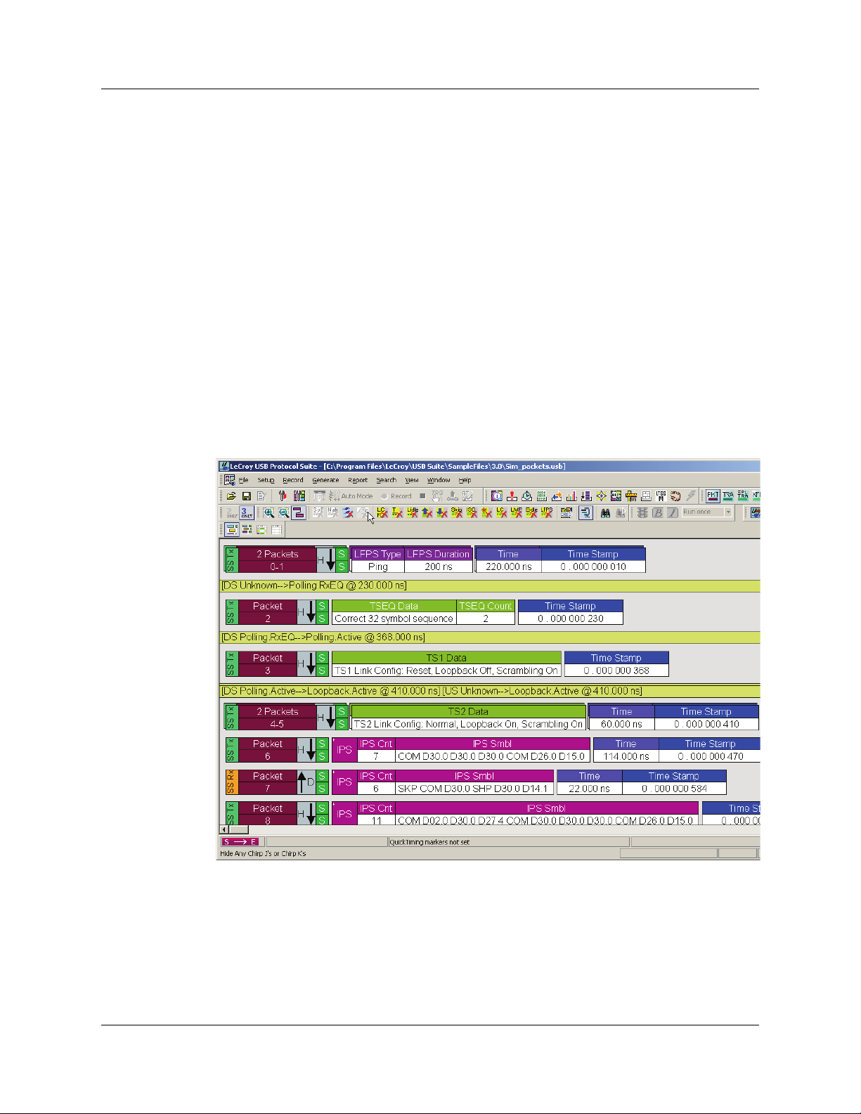
1.1.1 Graphical Bus Traffic Display
Bus traffic displays use color and graphics to show captured transactions.
Packets are on separate rows. Packets receive time stamps and sequential numbers as
the system records them. Fields have labels and color codes. The system automatically
detects protocol errors and highlights them in red.
You can customize the display color scheme and field formats. You can use the hide
feature to suppress SOF packets and uninteresting user-defined packets or fields in
different contexts. You can name and save display formats for later use. Pop-up tooltips
annotate packet fields.
The display software operates independently of the hardware, allowing it to function as a
stand-alone “trace viewer” that you can freely distribute.
Figure 1.1 Trace Viewer
LeCroy Corporation 1
Page 16

Chapter 1: Overview USB Protocol Suite User Manual
1.1.2 Accurate Time Measurement (Voyager, Advisor T3)
The internal counter/timer circuitry enables reliable, accurate (2 ns resolution)
time stamping of recorded bus traffic. Traces and measurement and analysis functions
display this timing information. Time fields are time stamps, idle times, bit times, or time
deltas, in either decimal or hexadecimal format. You can add any number of markers to
denote specific packets, you can make further timing measurements from one marker to
another or from marker to trigger.
An essential feature of time management is that idle traffic does not consume Analyzer
memory. Because of this unique technology, the system can make accurate timing
calculations while still preserving valuable recording memory for important bus traffic.
The oscillator has 2.5 ppm accuracy.
1.1.3 CrossSync Control Panel (Voyager, Advisor T3)
The LeCroy CrossSync control panel provides synchronization for complete end-to-end
visibility into multi-protocol systems.
CrossSync is LeCroy’s analyzer synchronization solution that enables time-aligned
display of protocol traffic from multiple daisy-chained analyzers showing packet traffic
from multiple high-speed serial busses. A lightweight software control panel allows users
to select analyzers for synchronization and manage the recording process. Captured
traffic is displayed using the latest analyzer software (in separate windows) with all the
protocol specific search and reporting features.
Captured packets are displayed in separate windows that share a common time scale.
Navigating the traffic in either direction will scroll to the same timestamp in a
synchronized window. When using the CrossSync option, users can access the full
complement of analysis capabilities available within the individual LeCroy software.
Search, reporting, and decoding all operate normally.
This feature is available with the LeCroy USB Protocol Suite application.
1.1.4 Comprehensive Error Detection and Analysis
The system detects, and alerts you to, every potential bus error and protocol violation,
and their combinations. The Analyzer BusEngine™ circuitry performs real-time triggering
on multiple error conditions, such as PID bad, bit stuffing bad, header or data CRC bad,
end-of-packet bad, babble, activity loss, frame length violation, time-out or turn-around
violation, and data toggle violation. The Analyzer program highlights all
hardware-detected errors and further examines the trace file for additional
protocol errors, including wrong packet length, data payload violation, and
packet termination not on a byte boundary.
2 LeCroy Corporation
Page 17

USB Protocol Suite User Manual Chapter 1: Overview
1.1.5 Real-Time Event Triggering and Capture Filtering
The Analyzer can accurately identify and selectively record transactions of interest from
the crowded stream of bus traffic. The system uses more than a dozen configurable
hardware building blocks that you can optimize to perform particular activities. Such
“recording resources” can independently await an initialization signal, monitor its external
environment (external signals or other resources) in search of a particular event, and take
a subsequent action, such as triggering, inclusive or exclusive filtering, and counting. In
the user interface, you can select, configure, and combine these resources to search for
complex trigger conditions and selectively capture associated transactions.
The system can trigger on basic events, such as specific bus conditions and
packet identifiers (PID). It can also trigger on complex events, such as “trigger on the
fifth occurrence of a SETUP Token device number nine” or “trigger on a SET INTERFACE
request, following a specified eight-byte bulk data pattern match from this scanner, and
do not capture any start-of-frame (SOF) packets.”
You can set the size of the recording memory, specify the pre-trigger to post-trigger
capture ratio, and truncate large data packets up to 256 bytes.
1.1.6 Advanced Event Counting and Sequencing
The count and sequence options define rules for data recording sessions. These options
configure and control the order of events selected for triggering or filtering.
Using this feature, you can specify a sequence of up to seven events that must occur
before the Analyzer triggers and finishes capturing data, allowing you to specify
event types for recording. Without this feature, you may have to scroll through megabytes
of recorded data to locate an occurrence of a sequence.
1.1.7 BusEngine Technology
The Analyzer uses LeCroy BusEngine Technology. The BusEngine core uses Electrically
Programmable Logic Device (EPLD) technology and incorporates both a real-time
recording engine and configurable building blocks that implement data/state/error
detection, triggering, capture filtering, external signal monitoring, and event counting and
sequencing. Like the flash-memory-based firmware that controls its operation, all
BusEngine logic is fully field upgradeable, using configuration files.
LeCroy Corporation 3
Page 18
Chapter 1: Overview USB Protocol Suite User Manual
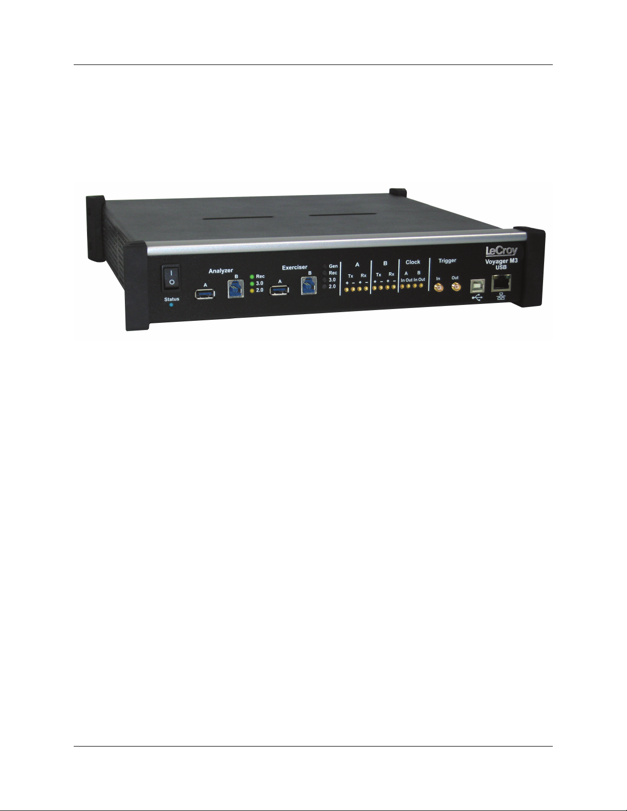
1.2 Voyager M3 Analyzer
The LeCroy Voyager M3™ Analyzer and Exerciser system is a multifunction verification
system for USB 2.0 and USB 3.0 development and testing. It can record traffic and
graphically present logical USB transactions and events. It can also generate USB traffic.
The system is connected to a laptop or desktop via its USB or Gigabit Ethernet port.
Figure 1.2 Voyager M3 Analyzer Exerciser System
Please see the Readme file on the installation CD for the latest
information on PC requirements and supported operating systems.
4 LeCroy Corporation
Page 19
USB Protocol Suite User Manual Chapter 1: Overview
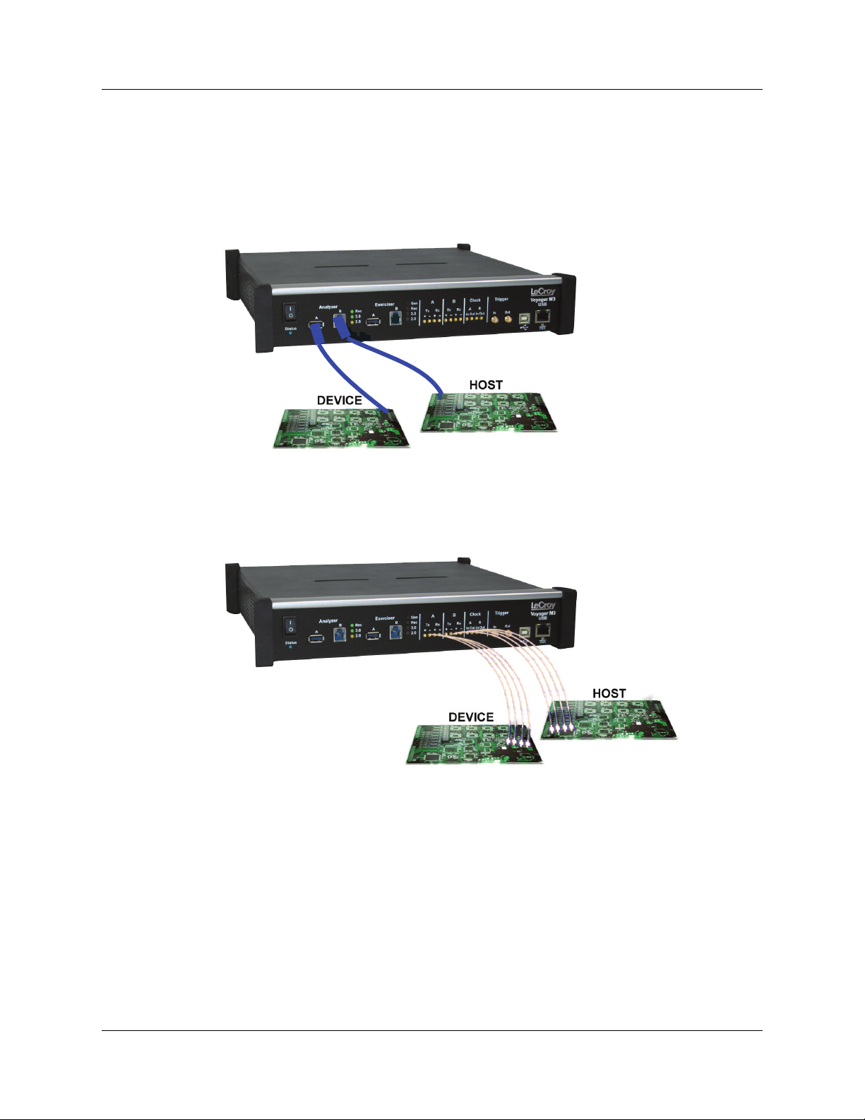
USB 2.0 and USB 3.0 Features
The system can monitor traffic between USB 2.0 links using standard high-speed
compliant cables.
If configured for USB 3.0 testing, the system supports monitoring between SuperSpeed
links using USB 3.0 cables (Figure 1.3)
Figure 1.3 Direct Connection using USB 3.0 Cables
or through direct connection via MMCx-to-SMA coaxial cables (Figure 1.4).
Figure 1.4 Direct Connection using SMA Differential Tap
LeCroy Corporation 5
Page 20

Chapter 1: Overview USB Protocol Suite User Manual
1.2.1 Voyager M3 General Description
The Analyzer connects to a portable or desktop PC through the USB port. The PC
configures and controls the Analyzer. The “CATC Trace™” user interface is an industry
standard for documenting the performance of high-speed serial protocols.
The USB protocol Analyzer provides traffic capture and analysis. Hardware triggering
allows capture of real-time events. Hardware filtering allows filtering different packet
types in or out of the recording. Filtering also allows you to preserve recording memory,
for extended recording time.
The trace viewer application displays recorded data in colored graphics. The application
has advanced search and viewing capabilities that allow you to quickly locate specific
data, errors, and other conditions.
The system functions with any personal computer having the Microsoft
Windows Vista™ 32, Windows Vista 64, or Windows 7 (32 or 64) operating system and
a functional USB interface or Ethernet port.
The system provides on-the-fly detection of, and triggering on, such events as Tokens
and Errors. Whether recording manually or with a specified trigger condition, the system
continuously records the link data, in a wrap-around fashion, until manually stopped or
until the system detects the Trigger Event and records the specified post-trigger amount
of link data.
Upon detection of a triggering event, the Analyzer continues to record data up to a point
specified by you. You can individually enable or disable real-time event detection to allow
triggering on events as they happen, including predefined exception or error conditions
and user-defined sets of trigger events. An externally supplied signal can trigger the
Analyzer.
®
Windows®XP,
You can use search functions to investigate particular events. In addition to immediate
analysis, you can print any part of the data. You can save the data on disk for later
viewing. You can generate timing information and data analysis reports.
Please refer to the Universal Serial Bus Specification for details on the protocol. The USB
specification is available from the USB Implementers Forum (USB-IF) at:
USB Implementers Forum
1730 SW Skyline Blvd.
Suite 203
Portland, OR 97221
Tel: +1/503.296.9892
Fax: +1/503.297.1090
Web: http://www.usb.org/
6 LeCroy Corporation
Page 21

USB Protocol Suite User Manual Chapter 1: Overview
1.2.2 Voyager M3 Features
General
• Fully complies with USB specification revisions.
• Supports the Link Power Management extension.
• Uses field-upgradeable firmware and recording engine.
• Supports all USB speeds (5 Gb/s, 480 Mb/s, 12 Mb/s, and 1.5 Mb/s).
• Displays bus traffic using color and graphics in the user-friendly CATC Trace
interface.
• Has free non-recording, view-only Trace Viewer software.
• Comes with online manual.
• Self-diagnoses at power on.
• Has a 36-month warranty and hot-line customer support.
• Uses software upgradable Exerciser function.
• Allows remote control of USB analyzers in a network.
Flexible 3.0 Calibration
Each link can be calibrated with respect to received equalization and gain.
Physical Components
• Desktop or portable Microsoft Windows XP, Windows Vista 32, Windows Vista 64,
or Windows 7 (32 or 64) computer with USB or Ethernet capability
• Plug-and-Play USB installation
• 1 GB or 4 GB of physical data-recording memory
• USB 2.0 Hi-Speed connection to desktop or portable host PC
• Internal wide-range AC power supply
• Expansion port for future enhancements
• SMA connectors and USB 3.0 connectors for SuperSpeed capture and generation
• External clock inputs and outputs
LeCroy Corporation 7
Page 22

Chapter 1: Overview USB Protocol Suite User Manual
Recording Options
• Versatile triggering: bit-wise value and mask data patterns up to sixteen bytes wide
for Setup transactions and data packets
• Triggering on new High-Speed PIDs and split transaction special tokens (ERR,
SPLIT, PING, NYET, DATA2, and MDATA) (2.0)
• CATC Trace display and enumeration of High-Speed Micro Frames (2.0)
• Three forms of triggering: Snapshot, Manual, and Event
• Transaction sequencer: Allows triggering on a token qualified by a data pattern
and/or specific handshake, or can filter transactions (for example, NAK’d
transactions) (2.0)
• Advanced triggering with event counting and sequencing
• Dedicated trigger for recording input and output used to interface to external test
equipment
• Triggering on multiple error conditions: PID bad, bit stuffing bad, CRC bad,
end-of-packet bad, babble, activity loss, frame length violation, time-out or
turn-around violation, data toggle violation, Token, Bus Conditions, Data Length,
and excessive empty frames (2.0)
• Real-time traffic capture filtering and data packet truncation variable up to 256 bytes
(2.0)
• Adjustable buffer size from 0.4 MB to 1 GB or 4 GB
• Idle filtering (3.0)
8 LeCroy Corporation
Page 23

USB Protocol Suite User Manual Chapter 1: Overview
Display Options
• Utilizes the CATC Trace graphical display of bus packets, transactions,
split transactions, and transfers.
• Groups numerous packets and transactions under a single transfer while quickly
decoding all essential information.
• Decodes split transactions upstream and downstream of a transaction translator
with a special hierarchical view.
• Has reports summarizing key statistics and conditions of interest, with the ability to
jump to the selected item in the trace display.
• Uses a Trace Viewer that is backward compatible with USB Advisor™,
USB Chief™, USB Inspector™, and USB Detective™ trace files, which are
converted upon loading.
• Indicates trigger position by different pre-trigger and post-trigger packet colors.
• Sets markers to assist with navigation and time calculations. Each marker can
contain unique comments.
• Hides start-of-frame (SOF) packets, as well as any packet or transaction from a
device address and endpoint.
• Searches for a specific PID.
• Detects and alerts you to every potential bus error and protocol violation, and their
combinations.
• Has high-resolution, accurate time stamping of bus packets and timing
measurement and analysis functions.
• Allows search and packet hiding.
• Allows device class decoding and user-defined protocol decoding.
• Has a Data View (2.0 and 3.0).
• Uses Link Tracker to view symbols of traffic (3.0).
• Uses a Spec View to show packets in the same format as the USB 3.0 specification
(3.0).
• Has Quick Timing Markers to immediately show time deltas and bandwidth use.
1.2.3 Hi-Speed Slow Clock
• Trace and generate High-Speed traffic at fractional (slow) clock rate capability (2.0)
LeCroy Corporation 9
Page 24

Chapter 1: Overview USB Protocol Suite User Manual
1.2.4 Traffic Generation
USB 2.0 and 3.0 traffic generation options allow you to transmit custom packets over
standard USB cables with low-level control of headers, payloads, timing, and link states.
The Exerciser can play back trace files bit-for-bit, allowing validation engineers to
recreate problems reported in the field or test-specific functionality.
To build generation script files, you can edit example test scenarios or export any traffic
stream from a previously recorded trace. The Voyager Exerciser includes a
Generation Script Editor.
A script pre-processor allows you to organize script code and create reusable generation
blocks.
For USB 3.0 applications, test scenarios can contain multi-stage traffic generation blocks
that include Boolean expressions, LOOP, DO-CASE, and IF-THEN logical branching.
The Voyager USB 2.0 Exerciser can transmit low, full, or high-speed traffic and supports
both host and device emulation. It is backward compatible with existing USBTra i n e r
traffic generation scripts.
For USB 2.0 applications, the Exerciser supports both bitstream mode or Intelliframe
mode. In Intelliframe mode, the Exerciser can wait for the appropriate response from the
DUT before transmitting the next packet. For example, after issuing an IN, the generator
waits for the DATAx packet returned by the device to finish, and then issues an ACK.
When NAKs are received, the Exerciser can automatically resend the previous packet.
Voyager ReadyLink™ Emulation
The LeCroy Voyager USB 3.0 Exerciser features ReadyLink Emulation Mode. The
ReadyLink feature handles all USB 3.0 link training and link flow control, allowing the
emulator to operate at full line rate and respond to the DUT as defined by the
specification. The ReadyLink Emulation Mode helps simplify development of USB 3.0
test scenarios.
By default, ReadyLink Emulation Mode automatically manages:
• Header Packet Acknowledgements (L_GOOD_n)
• Buffer Credit (L_CRD_x)
• SKIPs at required intervals (SKP)
• Link Synchronization
• Responds to LFPS (Polling.LFPS)
• Responds to polling sequence (Polling.RxEQ)
• Responds to TS1 / TS2 handshaking sequence
• Responds to SS.Inactive (with RX.Detect)
• Power Management Link Commands
• Responds to LGO_Un (with LAU)
• Responds to LAU (with LMPA)
10 LeCroy Corporation
Page 25

USB Protocol Suite User Manual Chapter 1: Overview
Test scripts can customize ReadyLink Emulation Mode to include error scenarios, such
as:
• Header LBADs
• Invalid link commands
• 8B10B / CRC Error
• Running Disparity Error
• Corrupt Link Commands
• Corrupt Flow Control (Wrong L_CRD_x, Wrong L_GOOD_n, Drop L_Good_n)
• Corrupt Header Packet acknowledgement (Send LBAD, LRTY)
• Corrupt Packet Framing (SHP, SDP, END)
At the packet level, you can send customized data payloads anywhere within the stream
to insert logic errors, perform corner-case, or do stress testing. Commands, such as the
Set ErrWrongLCRD command, allow link-layer error injection anywhere within the script.
1.2.5 Notes on LFPS Signals
Voyager Exerciser requires received “Ping” LFPS signals to be a minimum of
150 nanoseconds to be reliably recognized.
Voyager Analyzer can recognize “Ping” LFPS signals above 60 nanoseconds and report
their durations to
±15 nanoseconds of accuracy.
LeCroy Corporation 11
Page 26
Chapter 1: Overview USB Protocol Suite User Manual
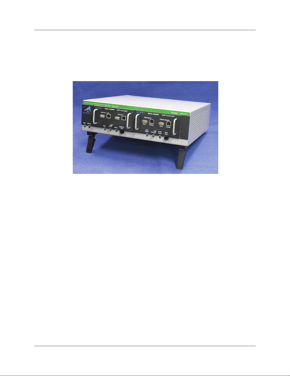
1.3 USBTracer/Trainer
The LeCroy USBTracer™ USB 2.0 Design & Verification System is the fifth generation
product of LeCroy's analysis tools for USB development and testing. The USB bus &
protocol Analyzer interfaces with standard USB cables and connections to capture and
display all speeds of USB 2.0 bus traffic.
Figure 1.5 USB Tracer/Trainer
1.3.1 USBTracer/Trainer General Description
The USBTracer™ hardware module installs into the LeCroy Universal Protocol Analyzer
System. A portable or desktop PC connects to USBTracer at its USB port and configures
and controls the Analyzer. The “CATC Trace™” user interface is the industry standard for
documenting the performance of high-speed serial protocols.
USBTracer non-intrusively provides traffic capture and analysis for USB protocol
development and testing. Hardware triggering allows real-time event capture. Hardware
filtering filters different types of packets in or out of the recording. Filtering also preserves
recording memory, so that recording time can be extended.
The trace viewer application displays recorded data in colored graphics. Advanced
search and viewing capabilities allow you to quickly locate specific data, errors, and other
desired conditions.
USBTracer functions with any personal computer using the Microsoft
Windows Vista™ 32, Windows Vista 64, or Windows 7 (32 or 64) operating system and
equipped with a functional USB interface.
®
Windows®XP,
12 LeCroy Corporation
Page 27
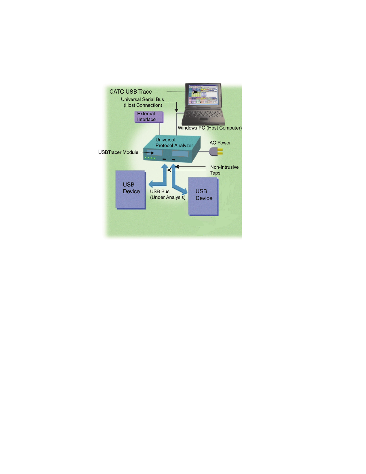
USB Protocol Suite User Manual Chapter 1: Overview
The Analyzer is a plug-in module that installs into a LeCroy Universal Protocol Analyzer
System (UPAS). Together, the Analyzer and UPAS are controlled from a personal
computer USB port across a USB connection.
Figure 1.6 System Setup
USBTracer provides on-the-fly detection of, and triggering on, events such as Tokens and
Errors. Whether recording manually or with a specified trigger condition, USBTracer
continuously records the link data in a wrap-around fashion until manually stopped or until
the system detects a Trigger Event and records the specified post-trigger amount of link
data.
Upon detection of a triggering event, the Analyzer continues to record data up to a point
specified by the user. You can individually enable or disable real-time detection of events
to allow triggering on events as they happen, including predefined exception or error
conditions and user-defined sets of trigger events. An externally supplied signal can
trigger the Analyzer. An external DB-25 connector provides a path for externally supplied
data or timing data to be recorded along with traffic.
The DB-25 connector also provides a path for USBTracer to transmit externally the
software trigger signal or a user-defined event, for probing or use by other circuitry.
Search functions allow the software to identify and highlight specific events. In addition
to immediate analysis, you can print any part of the data. You can save the data on disk
for later viewing. You can generate timing information and data analysis reports.
LeCroy Corporation 13
Page 28

Chapter 1: Overview USB Protocol Suite User Manual
Please refer to the Universal Serial Bus Specification, version 2.0 for details on the
protocol. The USB specification is available from the USB Implementers Forum (USB-IF)
at:
USB Implementers Forum
1730 SW Skyline Blvd.
Suite 203
Portland, OR 97221
Tel: +1/503.296.9892
Fax: +1/503.297.1090
Web: http://www.usb.org/
1.3.2 USBTracer/Trainer Features
General
• Fully complies with USB specification revision 2.0.
• Supports Link Power Management extension to USB 2.0 specification.
• Allows reconfigurable hardware for future enhancements.
• Has field-upgradeable firmware and recording engine.
• Supports all USB speeds (480 Mb/s, 12Mb/s, and 1.5 Mb/s).
• Has dual recording channels to aid development of multiple speed functions
upstream and downstream of speed-matching hub or transaction translator.
• Displays bus traffic using color and graphics in the CATC Trace interface.
• Has free non-recording, view-only Trace Viewer software.
• Comes with online manual.
• Self-diagnoses at power on.
• Has a 36-month warranty and hot-line customer support.
• Works in conjunction with the LeCroy USBTrainer USB Traffic Generator hardware
module to create a fully customizable USB test platform.
Physical Components
• Hardware module for the LeCroy Universal Protocol Analyzer System
• Desktop or portable Microsoft Windows XP, Windows Vista 32, Windows Vista 64,
or Windows 7 (32 or 64) computer with USB capability
• Plug-and-Play USB installation
• High-impedance tap: Inserts non-intrusively in any branch of a USB system.
• 512 MB of physical data-recording memory
• Two all speed (Low, Full, or Hi-Speed) recording channels
• Full-Speed USB connection to desktop or portable host PC. Hi-Speed on
UPAS 2500H platform.
• Internal wide-range AC power supply
• Break-out board to interface to external test equipment
14 LeCroy Corporation
Page 29

USB Protocol Suite User Manual Chapter 1: Overview
Recording Options
• Versatile triggering: bit-wise value and mask data patterns up to sixteen bytes wide
for Setup transactions and data packets
• Triggering on new High-speed PIDs and split transaction special tokens (ERR,
SPLIT, PING, NYET, DATA2, and MDATA).
• CATC Trace displays and enumerates High-speed Micro Frames.
• Three forms of triggering: Snapshot, Manual, and Event.
• Transaction sequencer: Allows triggering on a token qualified by a data pattern
and/or specific handshake, or can filter transactions (such as NAK’d transactions).
• Advanced triggering with event counting and sequencing
• Dedicated trigger for recording input and output used to interface to external test
equipment
• Triggering on multiple error conditions: PID bad, bit stuffing bad, CRC bad,
end-of-packet bad, babble, activity loss, frame length violation, time-out or
turn-around violation, data toggle violation, Token, Bus Conditions, Data Length,
and excessive empty frames
• Real-time traffic capture filtering and data packet truncation variable up to 256 bytes
• Adjustable buffer size from 0.4 MB to 512 MB
Display Options
• Uses the CATC Trace graphical display of bus packets, transactions,
split transactions, and transfers.
• Groups numerous packets and transactions under a single transfer while quickly
decoding all essential information.
• Decodes split transactions upstream and downstream of a transaction translator
with a special hierarchical view.
• Has reports summarizing key statistics and conditions of interest, with the ability to
jump to the selected item in the trace display.
• Records flexible input signaling with the CATC Trace.
• Uses a Trace Viewer backward compatible with Advisor™, Chief™, Inspector™,
and Detective™ trace files.
• Indicates trigger position by different pre-trigger and post-trigger packet colors.
• Sets markers to assist with navigation and time calculations. Each marker can
contain unique comments.
• Hides start-of-frame (SOF) packets and any packet or transaction.
• Searches for a specific PID.
• Detects, and alerts you to, every potential bus error and protocol violation, and their
combinations.
• Has high-resolution, accurate time stamping of bus packets and timing
measurement and analysis functions.
• Has search and packet hiding capabilities.
• Allows comprehensive device class decoding and user-defined protocol decoding.
LeCroy Corporation 15
Page 30

Chapter 1: Overview USB Protocol Suite User Manual
1.3.3 Traffic Generation
Traffic generation capability is available as an add-on module, USBTra i n e r ™ , for the
Universal Protocol Analyzer System.
1.3.4 Hi-Speed Slow Clock
The ability to trace and generate Hi-Speed traffic at fractional (slow) clock rate is available
on both USBTracer platforms (2500 and 2500H). You can purchase this feature with a
License Key. Contact LeCroy for more information.
16 LeCroy Corporation
Page 31

USB Protocol Suite User Manual Chapter 1: Overview
1.4 Advisor
The LeCroy Advisor™ USB 2.0 Bus & Protocol Analyzer is a LeCroy fourth-generation
product for USB development and testing. The Advisor interfaces with standard USB
cables and connections to capture and display Hi-Speed and Classic-Speed USB 2.0 bus
traffic.
Figure 1.7 Advisor
1.4.1 Advisor Features
General
• Fully complies with USB 2.0 specification
• Supports Link Power Management extension to USB 2.0 specification.
• Has reconfigurable hardware for future enhancements.
• Supports all USB speeds (High-Speed, Full-Speed, and Low-Speed).
• Displays bus traffic using color and graphics in the CATC Trace interface.
• Has free non-recording, view-only Trace Viewer software.
• Self-diagnoses at power on.
• Has a 36-month warranty and hot-line customer support.
LeCroy Corporation 17
Page 32

Chapter 1: Overview USB Protocol Suite User Manual
Physical Components
• High impedance tap: Inserts non-intrusively in any branch of a USB system
• 128 MB of physical data-recording memory
• Two recording channels: one for High-Speed traffic and one for Classic-Speed traffic
(either Low-Speed or Full-Speed)
• Secondary recording channel for development of multiple speed functions
up-stream and down-stream of a speed-matching hub or transaction translator
• Convenient “Detach Device” switch operates with the Classic recording channel to
save time and reduce USB cable/connector wear for multiple connects and
disconnects to host
• Full-speed USB connection to desktop or portable host PC
• Internal wide-range AC power supply
• Breakout board (included)
Recording Options
• Triggering on all USB2.0 PIDS and special tokens (such as ERR, SPLIT, PING,
NYET, DATA2, and MDATA).
• CATC Trace display and enumeration of USB2.0 Micro Frames
• Three forms of triggering: Snapshot, Manual, and Event
• High, Full, and Low speed traffic capture
• Adjustable buffer size from 0.1 MB to 128 MB
• Versatile triggering: bit-wise value and mask data patterns up to sixteen bytes wide
for Setup transactions and data packets
• Triggering on multiple error conditions: PID bad, bit stuffing bad, CRC bad,
end-of-packet bad, babble, activity loss, frame length violation, time-out or
turn-around violation, and data toggle violation
• Transaction sequencer: Allows triggering on a token qualified by a data pattern
and/or specific handshake, or can filter transactions.
• Advanced triggering with event counting and sequencing
• Dedicated trigger for recording input and output that is used to interface to external
test equipment
• Real-time traffic capture filtering and data packet truncation variable up to 245 bytes
18 LeCroy Corporation
Page 33

USB Protocol Suite User Manual Chapter 1: Overview
Display Options
• Uses the CATC Trace graphical display of bus packets, transactions,
split transactions, and transfers
• Has a Trace Viewer backward compatible with Chief™, Inspector™, and
Detective™ trace files.
• Indicates trigger position by different pre-trigger and post-trigger colors.
• Set markers to assist with navigation and time calculations. Each marker can
contain unique comments.
• Hides start-of-frame (SOF) packets and any packet or transaction.
• Search for a specific PID.
• Change bit order for all fields, except Data Length, Time, and
Packet # (MSB>LSB or LSB>MSB).
• Detects, and alerts you to, every potential bus error and protocol violation, and their
combinations.
• Has high-resolution, accurate time stamping of bus packets and timing
measurement and analysis functions.
• Has search and packet hiding capabilities.
• Allows comprehensive device class decoding and user-defined protocol decoding.
Refer to Readme.txt on your installation CD for the latest information on
features.
LeCroy Corporation 19
Page 34

Chapter 1: Overview USB Protocol Suite User Manual
1.5 Advisor T3
The LeCroy USB Advisor T3™ USB 3.0 Protocol Analyzer is a verification system for
USB development and testing. It supports both USB 2.0 and USB 3.0. It can record USB
traffic and graphically present the logical transactions and events. It connects to a laptop
or desktop PC through its USB port.
Figure 1.8 Advisor T3
The system can monitor traffic between USB 2.0 links using standard high-speed
compliant cables.
If configured for USB 3.0 testing, the system supports monitoring between SuperSpeed
links using USB 3.0 cables.
Please see the Readme file on the installation CD for the latest
information on PC requirements and supported operating systems.
20 LeCroy Corporation
Page 35

USB Protocol Suite User Manual Chapter 1: Overview
1.5.1 Advisor T3 General Description
The Analyzer connects to a portable or desktop PC through its USB port. The PC
configures and controls the Analyzer. The “CATC Trace™” user interface is an industry
standard for documenting the performance of high-speed serial protocols.
The USB protocol Analyzer provides traffic capture and analysis. Hardware triggering
allows capture of real-time events. Hardware filtering allows filtering different packet
types in or out of the recording. Filtering also allows you to preserve recording memory,
for extended recording time.
The trace viewer application displays recorded data in colored graphics. The application
has advanced search and viewing capabilities that allow you to quickly locate specific
data, errors, and other conditions.
The system functions with any personal computer having the Microsoft
Windows Vista™ 32, Windows Vista 64, or Windows 7 (32 or 64) operating system and
a functional USB interface.
The system provides on-the-fly detection of, and triggering on, such events as Tokens
and Errors. Whether recording manually or with a specified trigger condition, the system
continuously records the link data, in a wrap-around fashion, until manually stopped or
until the system detects the Trigger Event and records the specified post-trigger amount
of link data.
Upon detection of a triggering event, the Analyzer continues to record data up to a point
specified by you. You can individually enable or disable real-time event detection to allow
triggering on events as they happen, including predefined exception or error conditions
and user-defined sets of trigger events. An externally supplied signal can trigger the
Analyzer.
®
Windows®XP,
You can use search functions to investigate particular events. In addition to immediate
analysis, you can print any part of the data. You can save the data on disk for later
viewing. You can generate timing information and data analysis reports.
Please refer to the Universal Serial Bus Specification for details on the protocol. The USB
specification is available from the USB Implementers Forum (USB-IF) at:
USB Implementers Forum
1730 SW Skyline Blvd.
Suite 203
Portland, OR 97221
Tel: +1/503.296.9892
Fax: +1/503.297.1090
Web: http://www.usb.org/
LeCroy Corporation 21
Page 36

Chapter 1: Overview USB Protocol Suite User Manual
1.5.2 Advisor T3 Features
General
• Fully complies with USB specification revisions.
• Has field-upgradeable firmware.
• Supports all USB speeds (5 GB/s, 480 MB/s, 12 MB/s, and 1.5 MB/s).
• Displays bus traffic using color and graphics in the CATC Trace interface.
• Has free non-recording, view-only Trace Viewer software.
• Comes with online manual.
• Self-diagnoses at power on.
• Has a 36-month warranty and hot-line customer support.
• Allows remote control of USB analyzers in a network.
Flexible 3.0 Calibration
Each link can be calibrated with respect to received equalization and gain.
Physical Components
• Desktop or portable Microsoft Windows XP, Windows Vista 32, Windows Vista 64,
or Windows 7 (32 or 64) computer with USB capability
• Plug-and-Play USB installation
• 2 GB of physical data-recording memory
• USB 2.0 Hi-Speed connection to desktop or portable host PC
• DC power supply
• Expansion port for optional External Trigger In/Out cable, as well as multi-box
synchronized recording
• USB 3.0 connectors for SuperSpeed capture and generation
22 LeCroy Corporation
Page 37

USB Protocol Suite User Manual Chapter 1: Overview
Recording Options
• Versatile triggering: bit-wise value and mask data patterns up to sixteen bytes wide
for Setup transactions and data packets
• Triggering on new High-speed PIDs and split transaction special tokens (ERR,
SPLIT, PING, NYET, DATA2, and MDATA) (2.0)
• CATC Trace display and enumeration of High-Speed Micro Frames (2.0)
• Three forms of triggering: Snapshot, Manual, and Event
• Transaction sequencer: Allows triggering on a token qualified by a data pattern
and/or specific handshake, or can filter transactions (for example, NAK’d
transactions) (2.0)
• Advanced triggering with event counting and sequencing
• Dedicated trigger for recording input and output used to interface to external test
equipment
• Triggering on multiple error conditions: PID bad, bit stuffing bad, CRC bad,
end-of-packet bad, babble, activity loss, frame length violation, time-out or
turn-around violation, data toggle violation, Token, Bus Conditions, Data Length,
and excessive empty frames (2.0)
• Real-time traffic capture filtering and data packet truncation variable up to 256 bytes
(2.0)
• Adjustable buffer size from 0.4 MB to 2 GB
• Idle filtering (3.0)
LeCroy Corporation 23
Page 38

Chapter 1: Overview USB Protocol Suite User Manual
Display Options
• Uses the CATC Trace graphical display of bus packets, transactions,
split transactions, and transfers.
• Groups numerous packets and transactions under a single transfer while quickly
decoding all essential information.
• Decodes split transactions upstream and downstream of a transaction translator
with a special hierarchical view.
• Has reports summarizing key statistics and conditions of interest, with the ability to
jump to the selected item in the trace display.
• Has a Trace Viewer backward compatible with USB Advisor™, USB Chief™,
USB Inspector™, and USB Detective™ trace files, which are converted upon
loading.
• Indicates trigger position by different pre-trigger and post-trigger colors.
• Sets markers to assist with navigation and time calculations.
• Hides start-of-frame (SOF) packets and any packet or transaction from a device
address and endpoint.
• Searches for a specific PID.
• Detects, and alerts you to, every potential bus error and protocol violation, and their
combinations.
• Has high-resolution, accurate time stamping of bus packets and timing
measurement and analysis functions.
• Has search and packet hiding capabilities.
• Allows comprehensive device class decoding and user-defined protocol decoding.
• Has a Data View (2.0 and 3.0).
• Uses Link Tracker to view symbols of traffic (3.0).
• Has a Spec View to show packets in the same format as the USB 3.0 specification
(3.0).
• Uses Quick Timing Markers to immediately show time deltas and bandwidth use.
24 LeCroy Corporation
Page 39

USB Protocol Suite User Manual Chapter 1: Overview
1.6 USBMobile T2
The LeCroy USBMobile T2™ is a portable hardware-based USB 2.0 protocol analyzer
that debugs, tests, and verifies low, full, and high-speed USB devices. The USBMobile
T2 fits into a single PCMCIA slot in a laptop computer. The USBMobile T2 uses the
standard CATC Trace display.
Figure 1.9 USBMobile T2
The USBMobile T2 is available in three configurations that can be upgraded to add the
advanced functionality shown:
LeCroy Corporation 25
Page 40

Chapter 1: Overview USB Protocol Suite User Manual
1.6.1 Features
Features Benefits
Low-power, 16-bit, Type II
PC Card Design
CATC Trace software
display
OTG (On-The-Go)
Support
Trace Navigator Defines areas of interest and “shrinks” the viewable Trace to areas
Advanced Triggering Isolates important traffic, specific errors, or data patterns.
Hardware Filtering Removes non-essential fields from the trace for faster analysis.
Intelligent Reporting Quickly identifies and tracks error rates and abnormal bus or
Sophisticated Viewing Displays Packet, Transaction, and Transfer layers of the USB
Downloadable Trace
Viewer Software
Personal analyzer
Portable operation with any notebook PC
Speeds interpretation and debug of USB traffic. Compatible with
LeCroy USBMobile™, Inspector™, Chief™, Advisor™, and
USBTracer/Trainer ™.
Records and analyzes HNP and SRP, including capture of VBus
pulses
of most importance.
timing conditions.
protocol.
Shares and annotates trace recordings within a development
team.
General
• Fully complies with USB 2.0 specification.
• Supports Link Power Management extension to USB 2.0 specification.
• Supports Full-Speed, Low-Speed, and Hi-Speed USB.
• Displays bus traffic using color and graphics in the “CATC Trace™” interface.
• Has free non-recording, view-only Trace Viewer software.
• Has a 12-month warranty and hot-line customer support.
Physical Components
• PC-Card form: Personal analyzer. Low-power, portable operation with any notebook
PC.
• Two Mini AB USB ports and cables: Designed to reduce bulk and maintain
portability and compact size.
• 64 MB of physical data-recording memory
26 LeCroy Corporation
Page 41

USB Protocol Suite User Manual Chapter 1: Overview
Recording Options
• Versatile triggering: bit-wise value and mask data patterns up to sixteen bytes wide
for Setup transactions and data packets
• Triggering on new High-Speed PIDs and split transaction special tokens
(ERR, SPLIT, PING, NYET, DATA2, and MDATA)
• CATC Trace display and enumeration of High-Speed Micro Frames
• Three forms of triggering: Snapshot, Manual, and Event
• Transaction sequencer: Allows triggering on a token qualified by a data pattern
and/or specific handshake, or can filter transactions (such as NAK’d transactions)
• Advanced triggering with event counting and sequencing
• Triggering on multiple error conditions: PID bad, bit stuffing bad, CRC bad,
end-of-packet bad, babble, activity loss, frame length violation, time-out or
turn-around violation, data toggle violation, Token, Bus Conditions, Data Length,
and excessive empty frames
• Real-time traffic capture filtering and data packet truncation variable up to 256 bytes
• Adjustable buffer size from 0.4 MB to 64 MB
Display Options
• Uses the CATC Trace graphical display of bus packets, transactions,
split transactions, and transfers.
• Groups numerous packets and transactions under a single transfer while quickly
decoding all essential information.
• Decodes split transactions upstream and downstream of a transaction translator
with a special hierarchical view.
• Has reports summarizing key statistics and conditions of interest, with the ability to
jump to the selected item in the trace display.
• Records flexible input signaling with the CATC Trace.
• Has a Trace Viewer backward compatible with USBTracer™, USBMobile™,
Advisor™, Chief™, Inspector™, and Detective™ trace files.
• Indicates trigger position by different pre-trigger and post-trigger colors.
• Sets markers to assist with navigation and time calculations.
• Hides start-of-frame (SOF) packets and any packet or transaction.
• Searches for a specific PID.
• Detects, and alerts the user to, every potential bus error and protocol violation, and
their combinations.
• Has high-resolution, accurate time stamping of bus packets and timing
measurement and analysis functions.
• Has search and packet hiding capabilities.
• Allows comprehensive device class decoding and user-defined protocol decoding.
LeCroy Corporation 27
Page 42

Chapter 1: Overview USB Protocol Suite User Manual
1.7 USBMobile HS
The LeCroy USBMobile HS™ USB Hi-Speed Analyzer is a portable, PC Card based, bus
and protocol analyzer that accurately and efficiently debugs, tests, and verifies Low, Full,
and Hi-Speed USB semiconductors, devices, software and systems.
Figure 1.10 USBMobile HS
USBMobile HS is the previous generation of PCMCIA USB Analyzer. Its features are
identical to USBMobile T2, with the exception that it allows for up to seven sequential
states in its triggering and filtering capabilities.
28 LeCroy Corporation
Page 43

USB Protocol Suite User Manual Chapter 2: General Description
Chapter 2: General Description
2.1 Voyager M3 System Components/Packing List
These system components are on the packing list:
• Voyager M3 Analyzer Exerciser System
• AC power cable
• USB cables (five)
• Installation CD-ROM, including documentation
• Micro to Standard USB adapter
• Mini to Standard USB adapter
• Quick Start Guide
Product documentation is on the Installation CD-ROM.
2.2 Voyager M3 PC Requirements
Please refer to the USBProtocolSuite_Readme.html file on the installation CD for the
current PC and operating system requirements.
2.3 Voyager M3 Analyzer
The Analyzer is shown in the figure.
Figure 2.1 Voyager M3 Analyzer Front
The Analyzer has the following features:
Power Switch (0/1)
Status LED (blue if system successfully initializes
red if hardware failure
green while initializing)
LeCroy Corporation 29
Page 44

Chapter 2: General Description USB Protocol Suite User Manual
Analyzer Ports A (downstream) and B (upstream)
Analyzer LEDs
Rec - Recording
Red if 2.0 recording enabled or 3.0 recording enabled in Analyzer mode
3.0 - USB 3.0
Off: No traffic or LFPS.
Solid Yellow: Only Polling LFPS
Slow Flashing Yellow: Low Power States
Fast Flashing Yellow: Symbol Traffic, Training (TS1/TS2/TSEQ)
Solid Green: Link Traffic (U0) LUP, LDN
Blinking Green: TP's and DP's (actual traffic)
2.0 - USB 2.0
Solid Yellow: FS SOF's, LS EOP's, or control endpoint traffic
Slow Flashing Yellow: LS Traffic on endpoints other than 0
(resets activity timer as in 3.0)
Fast Flashing Yellow: FS Traffic on endpoints other than 0
(resets activity timer as in 3.0)
Solid Green: HS SOF's or control endpoint traffic
Flashing Green: HS traffic on endpoints other than 0
(resets activity timer as in 3.0)
Exerciser Ports A (downstream) and B (upstream)
Exerciser LEDs
Gen - Generating
Green if generating enabled
Rec - Recording
Red if 3.0 recording enabled when in Exerciser mode
3.0 - USB 3.0
Off: No traffic or LFPS.
Solid Yellow: Only Polling LFPS
Slow Flashing Yellow: Low Power States
Fast Flashing Yellow: Symbol Traffic, Training (TS1/TS2/TSEQ)
Solid Green: Link Traffic (U0) LUP, LDN
Blinking Green: TP's and DP's (actual traffic)
2.0 - USB 2.0
unused
Note: USB 2.0 Link LEDs operate only while USB 2.0 Recording or
Real-Time Statistics (RTS) is running.
USB 3.0 LEDs always operate, unless USB 3.0 has been disabled in the
Recording Options General Tab.
A (downstream) - MMCx plug connectors for interfacing
B (upstream) with USB 3.0 signals
Tx + - Transmit pair
Rx + - Receive pair
Clock A (downstream) - MMCx plug connectors for interfacing
Clock B (upstream) with external clock source or sink
In - Connects to an external reference clock.
Out- Provides reference clock output.
30 LeCroy Corporation
Page 45

USB Protocol Suite User Manual Chapter 2: General Description
Tri gger
In - SMA external trigger input. Note: Threshold value is 0.8 V. Maximum value of
the external input signal which can be input is 5 V. Minimum value is 0 V.
Out- SMA external trigger output.
USB - Type B connector for connection to host computer
ETHERNET- Gigabit Ethernet connector for connection to host computer
Note: The rear has only a power connector.
Warning: Do not open the Voyager M3 enclosure. No operator serviceable
parts are inside. Refer servicing to LeCroy customer care.
LeCroy Corporation 31
Page 46

Chapter 2: General Description USB Protocol Suite User Manual
2.4 Voyager M3 Specifications
The Analyzer has the following specifications.
2.4.1 Power Requirements
90 to 254 VAC, 47 to 63 Hz (universal input), 100 W maximum
2.4.2 Environmental Conditions
Operating Temperature 0 to 55 °C (32 to 131 °F)
Storage Range -20 to 80 °C (-4 to 176 °F)
Operating Humidity 10 to 90%, non-condensing
Operating Altitude Up to 6560 feet (2000 meters)
2.4.3 Probing Characteristics
Connection SuperSpeed connectors
USB 3.0 cables
MMCx connectors for USB 3.0
High Speed USB Connectors
Standard cables
2.4.4 Switches
Power On/off
2.4.5 Recording Memory Size
1 GB or 4 GB for traffic data capture, timing, state and other data.
32 LeCroy Corporation
Page 47

USB Protocol Suite User Manual Chapter 2: General Description
2.5 USBTracer/Trainer System Components
• One stand-alone USBTracer™ Analyzer module
• Five USB cables
•USBTracer software program installation diskettes
• Product documentation
2.6 USBTracer/Trainer Analyzer PC Requirements
Please refer to the USBProtocolSuite_Readme.html file on the installation CD for the
most current PC and operating system requirements.
2.7 The Installed USBTracer Unit
USBTracer is a module that inserts into the left slot on the LeCroy Universal Protocol
Analyzer System (UPAS). Once installed, the USBTracer Analyzer activates the
user-accessible controls and LEDs on the front and rear panels of the UPAS.
Figure 2.2 USBTracer Front Panel
Figure 2.3 USBTracer Rear Panel
LeCroy Corporation 33
Page 48

Chapter 2: General Description USB Protocol Suite User Manual
2.7.1 LED and Button Descriptions
This section describes the LEDs, buttons, and connectors on the module and UPAS.
LEDs on the Far Left Side of the UPAS
•Green PWR (Power) indicator LED for UPAS: Lights when unit power is
switched on.
•Red Status indicator LED for UPAS: Lights during boot up.
LEDs and Button on the UPAS under the Left Module Slot
The LEDs and button on the UPAS enclosure under the left module slot function in
conjunction with the USBTra cer module inserted above it:
•Green REC (Recording) LED: Lights when the unit is recording.
• Orange TRG (Triggered) LED: Lights when the unit triggers on an event.
•Green UPLD (Upload): Lights when unit is uploading data to PC.
• Manual Trigger push-button: Allows a manual Trace capture.
LEDs and Button on the UPAS under the Right Module Slot
The LEDs and button under the right module slot are reserved for LeCroy generator
modules such as the USBTrainer USB Traffic Generator (described in Traffic Generation
(2.0) on page 277):
•Green HS: Illuminates when Hi-Speed is being generated.
• Orange Classic: Illuminates when Full or Low Speed is being generated.
Classic also illuminates during power-on testing and is turned off at the end of
the power-on cycle. If the LED blinks at the end of this cycle, the hardware is
faulty.
•Green Intelliframe: Illuminates when Intelliframe traffic is being generated
using Intelliframe mode, an intelligent adaptive traffic mode. If off, the
generation is in Bitstream mode. See “Traffic Generation Modes: Bitstream
vs. Intelliframe” on page 291 for more information.
• Start/Stop: Push-button allows manual Trace capture.
2.7.2 Back Panel
• Wide range AC connector module:
• Power socket
• Power on/off switch
• Enclosed 5x20 mm, 2.0 A, 250 V fast-acting glass fuse
Warning! For continued protection against fire, replace fuse only with the type and
rating specified above.
• Ext. In: Threshold value is between 0.8 V and 2 V, because it uses TTL.
Maximum value of the external input signal which can be input is 5 V.
Minimum value is 0 V.
• Ext. Out: Uses TTL.
• USB type B host computer connector
• Data In/Out DB-25 (25-pin) external interface connector
Warning! Do not open the UPAS enclosure. There are no operator serviceable parts
inside. Refer servicing to LeCroy.
34 LeCroy Corporation
Page 49

USB Protocol Suite User Manual Chapter 2: General Description
2.8 USBTracer System Setup
The USBTracer module inserts into the Universal Protocol Analyzer System. The UPAS
connects to a desktop or laptop PC through a USB port. The PC controls the UPAS and
Analyzer.
To set up the system hardware:
• Insert the USBTracer module into the UPAS.
• Connect the Analyzer to an AC power source.
• Connect to the analyzing PC with USB.
• Connect USB cable to the device under test.
2.9 USBTracer/Trainer Specifications
USBTracer is a hardware module that installs into the Universal Protocol Analyzer
System. The following specifications describe a combined USBTracer/Universal Protocol
Analyzer System.
2.9.1 Package
UPAS 12.2 x 12.2 x 3.5 inches
(31.1 x 31.1 x 8.9 cm)
USBTrac er Plug-in 4.5 x 6.7 x 1.3 inches
(11.3 x 17.0 x 3.2 cm)
2.9.2 Connectors
UPAS AC power connection
External trigger connection
Host connection (USB, type B)
2.9.3 Weight
UPAS
USBTrac er Plug-in
7.5 lb. (3.4 kg)
1.0 lb. (0.5 kg)
2.9.4 Power Requirements
90 to 254 VAC, 47 to 63 Hz (universal input), 100 W maximum
LeCroy Corporation 35
Page 50

Chapter 2: General Description USB Protocol Suite User Manual
2.9.5 Environmental Conditions
Operating Temperature 0 to 55 °C (32 to 131 °F)
Storage Range -20 to 80 °C (-4 to 176 °F)
Operating Humidity 10 to 90%, non-condensing
Operating Altitude Up to 6560 feet (2000 meters)
2.9.6 Probing Characteristics
Connection High Speed USB Connectors
Standard cables
2.9.7 Switches
Power On/off
Manual Trigger When pressed forces a trigger event
2.9.8 Indicators (LEDs)
UPAS
Power (PWR): Illuminated when the Analyzer is powered on.
Status (STATUS): Illuminated solid during self test, blinking during
failure, off when the Analyzer is functioning properly.
Recording (REC): Illuminated when the Analyzer is actively recording traffic data.
Triggered (TRG): Illuminated during power-on testing and when the Analyzer has
detected a valid trigger condition.
Uploading (UPLD): Illuminated when the Analyzer is uploading its
recording memory to the Host PC to display the CATC Trace.
36 LeCroy Corporation
Page 51

USB Protocol Suite User Manual Chapter 2: General Description
2.9.9 Recording Memory Size
512 MB DRAM for traffic data capture, timing, state, and other data.
Power Cord Set
Cord Manufacturer and Models:
• 180-0005-00 Quail 5000.079 UL, CSA
• 180-0013-00 Quail 8500.098 VDE, KEMA, CEBERC, NEMDO, DEMDO,
SETI, OVE, SEV
• 180-0014-00 Quail 9650.098 ASTA
USBTracer on the UPAS 2500H Platform
UPAS 2500H USBTracer is a USB 2.0 Certified Hi-Speed Device. To upload at Hi-Speed,
you must have a USB 2.0 Certified Host Controller and be running the
Microsoft Windows XP, Windows Vista 32, or Windows Vista 64 operating system.
The UPAS 2500H ships in one of two configurations: Classic and Hi-Speed. The Classic
version can trace and generate traffic at Low and Full Speeds. The Hi-Speed version can
trace and generate traffic at All speeds: Low, Full, and Hi.
The Classic model may be upgraded to a Hi-Speed model by purchasing a License Key
from LeCroy. Contact your LeCroy representative for more information.
Note: The UPAS 2500 and UPAS 2500H products include internal 1.1 and 2.0
Hubs. You might see the drivers for these generic hubs being installed upon
initial plug-in.
LeCroy Corporation 37
Page 52

Chapter 2: General Description USB Protocol Suite User Manual
2.10 USBTracer/Trainer External Interface Breakout Board
The External Interface Breakout Board is an accessory that allows convenient access to
several potentially useful standard LV TTL output and input signals. It also offers a simple
way to connect logic analyzers or other tools to the USBTracer Analyzer. Six ground pins
and one 5-volt pin are provided.
Figure 2.4 External Interface Breakout Board
The Breakout Board connects by cable to the Data In/Out connector located on the rear
of the Analyzer box. Each signaling pin is isolated by a 100 series resistor and a buffer
inside the Analyzer box.
Figure 2.5 Data In/Out Connector (on cable)
38 LeCroy Corporation
Page 53

USB Protocol Suite User Manual Chapter 2: General Description
2.10.1 Pin-Outs for the Data In/Out Connector
Table 1 lists the pin-out and signal descriptions for the Data In/Out connector on a cable
that connects to the Breakout Board.
Table 1 Data In/Out Connector – Pin-Out
Pin Signal Name Signal Description
1RSV Reserved
2 GND Ground
3 GP OUT General Purpose Output
4 TRG IN 1 Trigger In 1
5 GND Ground
6 DATA 6 Data 6
7 DATA 4 Data 4
8 DATA 3 Data 3
9 DATA 1 Data 1
10 GND Ground
11 RSV Reserved
12 RSV Reserved
13 +5V +5 Volts, 250 mA DC Source
14 RSV Reserved
15 GND Ground
16 TRG OUT Trigger Out
17 TRG IN 0 Trigger In 0
18 DATA 7 Data 7
19 DATA 5 Data 5
20 GND Ground
Note:
(*) Pins 4 and 17 have the same function. They allow external signals to be
used to cause triggering or recording. Pins 3 and 16 are used to transmit
output signals.
2.10.2 Prototype Rework Area
The Breakout Board contains a prototype rework area for making custom circuits for rapid
development. The area consists of plated-through holes, 20 columns wide by 27 rows
long. The top row of holes connects to GND, and the bottom row connects to +5 V. The
remaining holes are not connected. Use the rework area to insert custom components
and wire-wrap their respective signal, power, and ground pins.
LeCroy Corporation 39
Page 54

Chapter 2: General Description USB Protocol Suite User Manual
2.11 Advisor
The LeCroy USB Advisor™ USB 2.0 Protocol Analyzer is a stand-alone unit controlled
and configured by a portable or desktop PC connected through its USB port.
The Advisor uses hardware triggering to capture real-time events and hardware filtering
to preserve memory and find data. Recorded data uploads to the attached PC and
displays on the CATC Trace graphical user interface as color-coded packets that can be
searched for specific data, errors, or other conditions.
The Analyzer works with any Microsoft
Windows Vista 64 desktop or portable PC.
The Analyzer supports the Universal Serial Bus, version 2.0. Please refer to the
Universal Serial Bus Specification, version 2.0 for details on the protocol. The USB
specification is available from the USB Implementers Forum (USB-IF) at:
®
Windows®XP, Windows Vista™ 32, or
USB Implementers Forum
1730 SW Skyline Blvd. Suite 203
Portland, OR 97221
Tel: +1/503.296.9892
Fax: +1/503.297.1090
Web: http://www.usb.org/
2.12 Advisor PC Requirements
Please refer to the USBProtocolSuite_Readme.html file on the installation CD for the
most current PC and operating system requirements.
2.13 Advisor System Components/Packing List
The LeCroy Advisor Analyzer package includes the following items:
• One stand-alone LeCroy USB Advisor™ Analyzer module
• One AC power cord with a plug appropriate to your location
• One External Interface Breakout Board with a 9-pin cable
• Five USB cables: four 3-foot (1-meter) cables and one 6-foot (2-meter) cable
• LeCroy Advisor software program installation CD
• Product documentation, including online help
40 LeCroy Corporation
Page 55

USB Protocol Suite User Manual Chapter 2: General Description
2.14 Advisor Stand-Alone Unit
Figure 2.6 Advisor Front Panel
Figure 2.7 Advisor Rear Panel
The Analyzer has several user-accessible controls on its front and rear panels.
• Red PWR (power) indicator LED: Illuminates when the unit power is switched on.
• Green REC (recording) LED: Illuminates when the unit is recording.
• Yellow TRG (triggered) LED: Illuminates when the unit triggers an event. Also
lights during power-on testing and blinks when the hardware is faulty.
• Green UPLD (upload) LED: Illuminates when unit is uploading data to host PC.
• Manual Trigger push-button (allows a manual Trace capture)
• After beginning a recording session, press the Manual Trigger switch to force
a Trigger condition. The session completes when a specified post-trigger
amount of bus data is recorded or when you manually stop a recording
session.
• Detach Device push-button allows a momentary disconnection of the device
from the host on the Classic Speeds port. This is useful when interesting
traffic occurs during device enumeration. Use the Detach Device switch
shortly after starting recording to capture a Trace of the device’s enumeration.
• Two USB ports, High Speed and Classic Speed, each with a type A and a type B
connector.
• High Speed: Used to record 480 MB/s High-Speed traffic only
• Classic Speeds: Used to record either 12 MB/s or 1.5 MB/s Classic-Speed
traffic
LeCroy Corporation 41
Page 56

Chapter 2: General Description USB Protocol Suite User Manual
• Wide range AC connector module:
• Power socket
• Power on/off switch
• Enclosed 5x20 mm 2.0A 250 V fast acting glass fuse
Warning! For continued protection against fire, replace fuse only with the type and
rating specified above.
•USB type B host computer connector
• Data In/Out DB-9 (9-pin) external interface connector
Note: The BNC connector next to the Data In/Out 9-pin DIN connector DOES NOT
PROVIDE ANY USER FUNCTIONALITY! It may have the label EXT CLK,
AUX, or TRIGGER, depending on when it was manufactured.
Do not use the BNC connector for any purpose!
(The Trigger In and Trigger Out functions are only available through the
Breakout Board accessory.)
Warning! Do not open the Analyzer enclosure. There are no operator serviceable parts
inside. Refer servicing to LeCroy.
42 LeCroy Corporation
Page 57
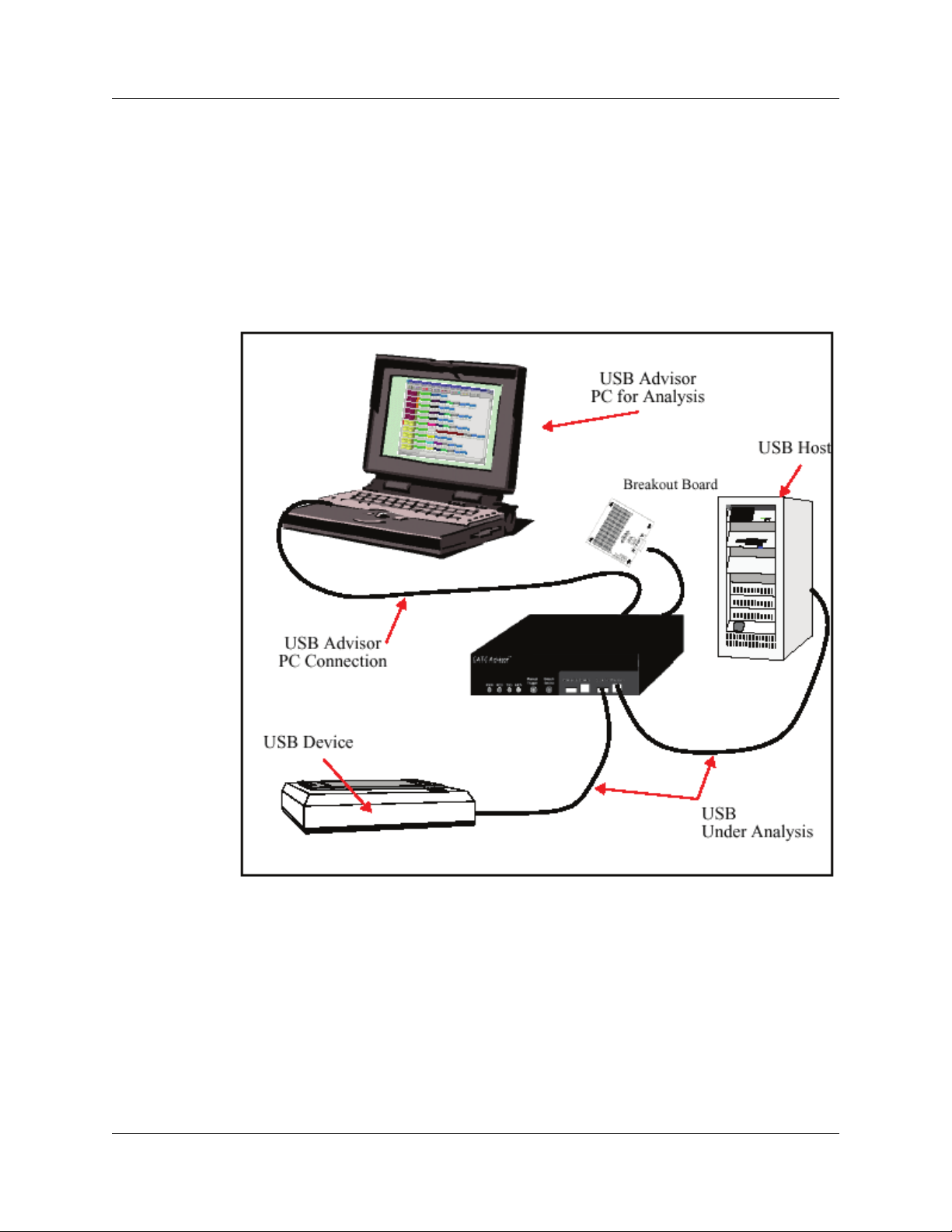
USB Protocol Suite User Manual Chapter 2: General Description
2.15 Advisor System Setup
The Analyzer functions with any personal computer using the Microsoft® Windows®XP,
Windows Vista™ 32, or Windows Vista 64 operating system and equipped with a
functional USB interface.
The Analyzer is a stand-alone unit configured and controlled through a personal
computer USB port. It can be used with portable computers for field service and
maintenance as well as with desktop units in a development environment. To install,
connect a cable between the computer’s USB port and the Analyzer’s USB port.
Figure 2.8 USB Advisor Connection
LeCroy Corporation 43
Page 58

Chapter 2: General Description USB Protocol Suite User Manual
2.16 Advisor Specifications
2.16.1 Package
Dimensions 9.2 x 8.4 x 2.5 inches
(23.4 x 21.3 x 6.4 cm)
Connectors AC power connection
Trigger IN/OUT input (BNC)
Host connection (USB, type B)
Data connector (Data In/Out, 9-pin DB)
Weight 2.8 lbs. (1.2 kg)
2.16.2 Power Requirements
90 to 254 V AC, 47 to 63 Hz (universal input), 100 W maximum
2.16.3 Environmental Conditions
Operating Temperature 0 to 55°C (32 to 131°F)
Storage Range -20 to 80°C (-4 to 176°F)
Operating Humidity 10 to 90%, non-condensing
Operating Altitude Up to 6560 feet (2000 meters)
2.16.4 Switches
Power on/off
Manual Trigger Forces trigger event.
Detach Device Detaches the device from the classic speed connection.
2.16.5 LEDs
Power (PWR) Illuminated when the Analyzer is powered on
Recording (REC) Illuminated when the Analyzer is actively recording traffic data
Triggered (TRG) Illuminated during power-on testing and when the Analyzer has
detected a valid trigger condition
Uploading (UPLD) Illuminated when the Analyzer is uploading its recording memory
to the host PC for display
2.16.6 Recording Memory Size
128 megabyte DRAM for traffic data capture, timing, state and other data
44 LeCroy Corporation
Page 59

USB Protocol Suite User Manual Chapter 2: General Description
2.17 Advisor External Interface Breakout Board
The External Interface Breakout Board is an accessory that allows convenient access to
several potentially useful standard, fast TTL output and input signals. It also offers a
simple way to connect logic Analyzers or other tools to the Analyzer unit. Four ground
pins and one 5-volt pin are provided.
Figure 2.9 External Interface Breakout Board
The Breakout Board connects by cable to the Data In/Out connector located on the rear
of the Analyzer box. Each signaling pin is isolated by a 100 series resistor and a buffer
inside the Analyzer box.
Figure 2.10 Data In/Out Connector (on cable)
LeCroy Corporation 45
Page 60

Chapter 2: General Description USB Protocol Suite User Manual
2.17.1 Pin-Outs for the Data In/Out Connector
Table 2 lists the pin-out and signal descriptions for the Data In/Out connector on a cable
that connects to the Breakout Board.
Table 2 Data In/Out Connector – Pin-Out
Pin Signal Name Signal Description
1 +5V +5 Volts, 250mA DC source
2 TRG IN (*) Trigger Input
3 GP IN (*) General Purpose Input
4 TRG OUT (*) Trigger Output
5 GP OUT (*) General Purpose Output
6 GND Ground
7 GND Ground
8 GND Ground
9 GND Ground
Note:
(*) Pins 2 and 3 have the same function: they allow external signals to be
used to cause triggering or recording. Pins 4 and 5 are used to transmit
output signals.
2.17.2 Prototype Rework Area
The Breakout Board contains a prototype rework area for making custom circuits for rapid
development. The area consists of plated-through holes, 20 columns wide by 27 rows
long. The top row of holes connects to GND, and the bottom row connects to +5 V. The
remaining holes are not connected. Use the rework area to insert custom components
and wire-wrap their respective signal, power, and ground pins.
2.17.3 PC Connection
Use the LONGEST (6-foot/2-meter) of the five USB cables provided to connect the host
computer to the Analyzer box.
46 LeCroy Corporation
Page 61

USB Protocol Suite User Manual Chapter 2: General Description
2.18 Advisor T3
The LeCroy USB Advisor T3™ USB 3.0 Protocol Analyzer is a verification system for
USB development and testing. It supports both USB 2.0 and USB 3.0. It can record USB
traffic and graphically present the logical transactions and events. It connects to a laptop
or desktop PC via USB 2.0.
The system can monitor traffic between USB 2.0 links using standard high-speed
compliant cables.
If configured for USB 3.0 testing, the system supports monitoring between SuperSpeed
links using USB 3.0 cables.
2.18.1 Components
The LeCroy Advisor T3 Analyzer package includes the following:
• One LeCroy USB Advisor T3 Analyzer
• DC Power Adaptor
• USB cables (three)
• Installation CD-ROM, including documentation
• Quick Start Guide
• Carrying Case
2.18.2 Front Panel
Figure 2.11 Advisor T3 Front Panel
The front panel has the following indicators and connectors:
Power LED (green if on)
Status LED (blue if system successfully initializes)
(red while booting. If red for more than a minute, hardware failure.)
(green while initializing)
Analyzer Port A (downstream) Connects to Device under test.
Analyzer Port B (upstream) Connects to Host.
Analyzer LEDs
Rec- Recording (red if recording enabled)
Tri g- Trigger (green if triggering)
2.0 - USB 2.0 (yellow for Low and Full Speed)
(green for Hi Speed)
3.0 - USB 3.0 (green if link is up; flashes green while data transfers;
yellow if polling)
LeCroy Corporation 47
Page 62

Chapter 2: General Description USB Protocol Suite User Manual
2.18.3 Rear Panel
Figure 2.12 Advisor T3 Rear Panel
The rear panel has the following indicators and connectors:
USB Type B connector for connection to host computer
Sync/Data: Micro DB-25 (25-pin) external interface connector
(cable sold separately)
Power Connector 12V, 3A DC
Power Switch (0/1)
Do not open the enclosure. No operator serviceable parts are inside. Refer
servicing to LeCroy customer care.
48 LeCroy Corporation
Page 63

USB Protocol Suite User Manual Chapter 2: General Description
USB
2.18.4 Advisor T3 System Setup
Advisor T3 is configured and controlled through a personal computer USB port.
Figure 2.13 Advisor T3 Setup
LeCroy Corporation 49
Page 64

Chapter 2: General Description USB Protocol Suite User Manual
2.19 USBMobile T2 and USBMobile HS
USBMobile T2 (and USBMobile HS) components are:
• One LeCroy USBMobile T2 Analyzer (or USBMobile HS Analyzer)
• One 1-meter A-B cable (standard A plug to mini B plug)
• One 1-meter A-B cable (mini A plug to mini B plug)
• One 15-centimeter On-the-Go (OTG) adaptor
(standard A receptacle to mini A plug)
• Installation CD
• USBMobile T2 Quick Start
Note: All USBMobile T2 items also apply to USBMobile HS.
2.19.1 Setup
Insert the USBMobile T2 card (or USBMobile HS card) into a PCMCIA slot on your host
computer.
Figure 2.14 USBMobile T2 Setup
Note: The USBMobile T2 (and USBMobile HS) card does not fit into an ExpressCard slot.
To install components:
Step 1 Connect a host to one of the mini A-B receptacles (use an adaptor if
necessary), and connect your device to the other. It does not matter
which receptacle into which you plug.
Step 2 Insert the CD-ROM.
Step 3 Click NEXT when you see the Add New Hardware Wizard window.
Step 4 Follow the on-screen Plug and Play instructions.
Step 5 Click Finish when you see the message that says “Windows has
finished installing the software that your new hardware requires” and the
file USBMobileT2.inf (or USBMobileHS.inf) has been installed on your
host PC.
Note:
USBMobile T2 (and USBMobile HS) USB is not a hub device. It connects to a USB
branch by inserting a non-intrusive, high-impedance tap. Because poor signal quality in
the middle of a USB cable, LeCroy recommends using the shortest possible cables, so
that total length of both cables together is less than six feet. The USB cables provided
with your Analyzer meet this requirement. When longer cables are used, the Analyzer
might record incorrect data.
50 LeCroy Corporation
Page 65

USB Protocol Suite User Manual Chapter 3: Installation
Chapter 3: Installation
The Analyzer software installs on a Microsoft® Windows®XP, Windows Vista™ 32,
Windows Vista 64, or Windows 7 (32 or 64) personal computer system.
Note: USBMobile T2 and USBMobile HS are not supported on 64-bit
operating systems.
Important!
Please uninstall any versions of USBTracer, USB Advisor, or USBMobile HS
software on your computer BEFORE installing USB Protocol Suite. The older
software is not compatible with the new software and device drivers. You can load
files recorded using the old software into USB Protocol Suite, which will
automatically convert them to the new format.
3.1 Installing the Analyzer Software on the PC
Note: You must install the software before connecting the Analyzer to the host
machine for the first time.
Install the software on the PC administering the Analyzer:
Step 1 Insert the Installation CD into the CD drive of the PC that administers the
Analyzer.
Step 2 Follow the on-screen installation instructions to install the application on the PC
hard disk.
3.2 Setting Up the Analyzer - USB Connection
To set up an Analyzer using a USB connection:
Step 1 Connect the AC power cord to the rear of the Analyzer and to a 100-volt to
240-volt, 50-Hz to 60-Hz, 100-W power outlet.
Note: The Analyzer is capable of supporting supply voltages between 100 volts
and 240 volts, 50 Hz or 60 Hz, thus supporting all supply voltages around the
world.
Step 2 Connect the USB port to a USB port on the PC using the LONG (6-foot/2-meter)
USB 2.0 cable.
Step 3 Insert the Installation CD.
Step 4 Turn on the power switch.
Note: At power-on, the Analyzer initializes itself in approximately ten seconds and
performs an exhaustive self-diagnostic that lasts about five seconds. If the
diagnostics fail, call LeCroy Customer Support for assistance.
Step 5 Click Next after you see the Add New Hardware Wizard window.
LeCroy Corporation 51
Page 66

Chapter 3: Installation USB Protocol Suite User Manual
Step 6 Follow the Microsoft® Windows® on-screen Plug-and-Play instructions for the
automatic installation of the Analyzer as a USB device on your analyzing PC (the
required USB files are included on the Installation CD).
Step 7 Click Finish when you see the message that says “Windows has finished
installing the software that your new hardware requires” and the driver files have
been installed in your PC.
Step 8 Check Analyzer setup in the “Application Startup” section (See “Application
Startup” on page 56).
Warning! Do not change from USB to Ethernet, or back, without power cycling the
Analyzer.
3.3 Setting Up the Analyzer - Ethernet Connection
To set up an Analyzer using an Ethernet connection:
Step 1 Connect the provided AC power cord to the rear of the Voyager M3 and to a
100-volt to 240-volt, 50-Hz to 60-Hz, 100-W power outlet.
Note: The Analyzer is capable of supporting supply voltages between 100 volts
and 240 volts, 50 Hz or 60 Hz, thus supporting all supply voltages around the
world.
Step 2 Insert the Installation CD.
Step 3 To use a DHCP network, make sure that the PC connects to a DHCP network,
then connect the Ethernet port on the Analyzer to the DHCP network.
Note: If the DHCP network uses a Firewall, you must set the Firewall to allow the
Analyzer device on the network.
Note: Direct connection from the Ethernet port on the PC to the Ethernet port on
the Analyzer is supported in this release. See “IP Settings (Voyager only)” on
page 58.
Step 4 Turn on the power switch.
Note: At power-on, the Analyzer initializes itself in approximately ten seconds and
performs an exhaustive self-diagnostic that lasts about five seconds. If the
diagnostics fail, call LeCroy.
Step 5 Complete Analyzer setup in the “Application Startup” section (See “Application
Startup” on page 56).
Warning! Do not change from USB to Ethernet, or back, without power cycling the
Analyzer.
52 LeCroy Corporation
Page 67

USB Protocol Suite User Manual Chapter 3: Installation
3.4 Cascading with CATC SYNC Expansion Card
You can cascade two Analyzers, if they both have a CATC SYNC port:
• Voyager requires a CATC Sync Expansion Card for cascading.
• Advisor T3 has a built-in CATC SYNC port and only requires a cross-connect
or octopus cable accessory.
After Analyzers are connected, recording will start simultaneously and triggers will occur
simultaneously, with synchronized timestamps.
You must select both Analyzers in the Device List dialog
(see “Analyzer Devices” on page 57).
Important: When you are NOT doing cascaded recording, you must UNPLUG the cable!
If you do not unplug, the electrical signal prevents recording on all Analyzers.
Note: In this software version, cascaded recording only works if you use two Voyagers
OR two Advisor T3s. You cannot use one of each. Also, you must enable 3.0
Auto-Detect/Termination mode. Manual control does not work.
3.4.1 Removing Expansion Cards
You can remove expansion cards using two tools:
• Standard (flat blade) 3/16” screwdriver
• LeCroy Extraction Tool (part number 230-0160-00)
LeCroy Corporation 53
Page 68

Chapter 3: Installation USB Protocol Suite User Manual
To remove an expansion card, follow these steps:
Step 1 Unplug the system from AC power and turn the system so the expansion port is
facing you. Note the two retaining screws and the holes for the extraction tool that
are located on the panel of the expansion card.
Note: The example shows a different expansion card, but the removal method is
the same.
Step 2 Insert the extraction-tool prongs into the holes in the expansion card panel.
Note: If the prongs do not slip easily into the holes, use a small nail file or similar
device to remove paint from the prongs.
Step 3 Rotate the extraction tool to a horizontal position to lock the prongs into place and
make a handle.
54 LeCroy Corporation
Page 69

USB Protocol Suite User Manual Chapter 3: Installation
Step 4 Using the screwdriver, loosen both retaining screws by rotating
counter-clockwise approximately two full turns, until feeling slight resistance.
Do not force the retaining screws after two turns.
Step 5 Using the extraction tool as a handle, gently wriggle the expansion card forward
about 1/8”.
Step 6 Repeat steps 4 and 5 approximately three times, until the card is free from the
retaining screws and you can remove the card from the system.
LeCroy Corporation 55
Page 70

Chapter 3: Installation USB Protocol Suite User Manual
3.5 Application Startup
To start the application, launch the LeCroy USB Protocol Suite program from the
Start Menu:
Start > Programs > LeCroy > USB Protocol Suite > USB Protocol Suite
to open the main window.
You can use the software with or without the system connected to the host. Without the
Analyzer, the program functions as a trace viewer to view, analyze, and print trace files.
3.5.1 Confirm Proper Hardware Installation and USB or Ethernet Connection
USB Connection
For USB connection, after you open the USB Protocol Suite application, confirm proper
installation and USB connection by selecting About from the Help menu to view the
Software Version, Firmware Version, BusEngine™ Version, and Unit Serial Number in
the About window.
Ethernet Connection (Voyager only)
For Ethernet connection, after you open the USB Protocol Suite application, confirm
proper installation and Ethernet connection using the Analyzer Devices dialog and the
About window.
56 LeCroy Corporation
Page 71
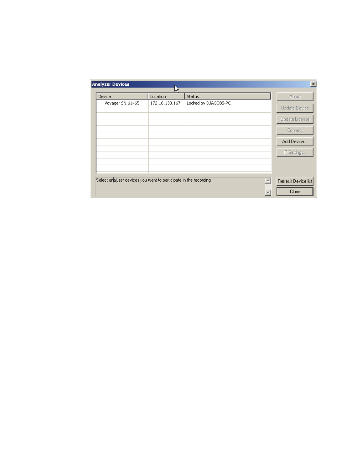
USB Protocol Suite User Manual Chapter 3: Installation
3.5.2 Analyzer Devices
To show the available Analyzer Devices, select Setup > All Connected Devices to
display the Analyzer Devices dialog.
The dialog displays the Device, Location, and Status.
You can click:
• About to display device information (see “Software, Firmware, and
BusEngine Revisions” on page 345).
• Update Device (see “Manual Updates to Firmware, BusEngine, and
Serdes BusEngine” on page 350)
• Update License (see “Updating the Software License” on page 352)
• Connect to display the Connection Properties dialog, in which you can set the
system to:
- Automatically connect to the device.
- Ask to connect to the device.
- Take no action.
• Add Device to display the Add Ethernet Attached Device dialog, in which you
can enter an IP Address.
• IP Settings to use a DHCP or Static IP address.
To refresh the list of devices, click Refresh Device List.
Before starting recording, select the Analyzer you want to use for recording.
LeCroy Corporation 57
Page 72

Chapter 3: Installation USB Protocol Suite User Manual
3.5.3 IP Settings (Voyager only)
If connected to a device, you can change the IP settings:
• DHCP automatically assigns an IP address. DHCP is the default.
• Static IP prompts you to enter a specific IP address.
To change from DHCP to Static IP while connected to a device:
Step 1 Select Setup > All Connected Devices from the menu bar to display the
Analyzer Devices dialog.
Note: If you are not connected to a device, the IP Settings command is grayed out.
58 LeCroy Corporation
Page 73
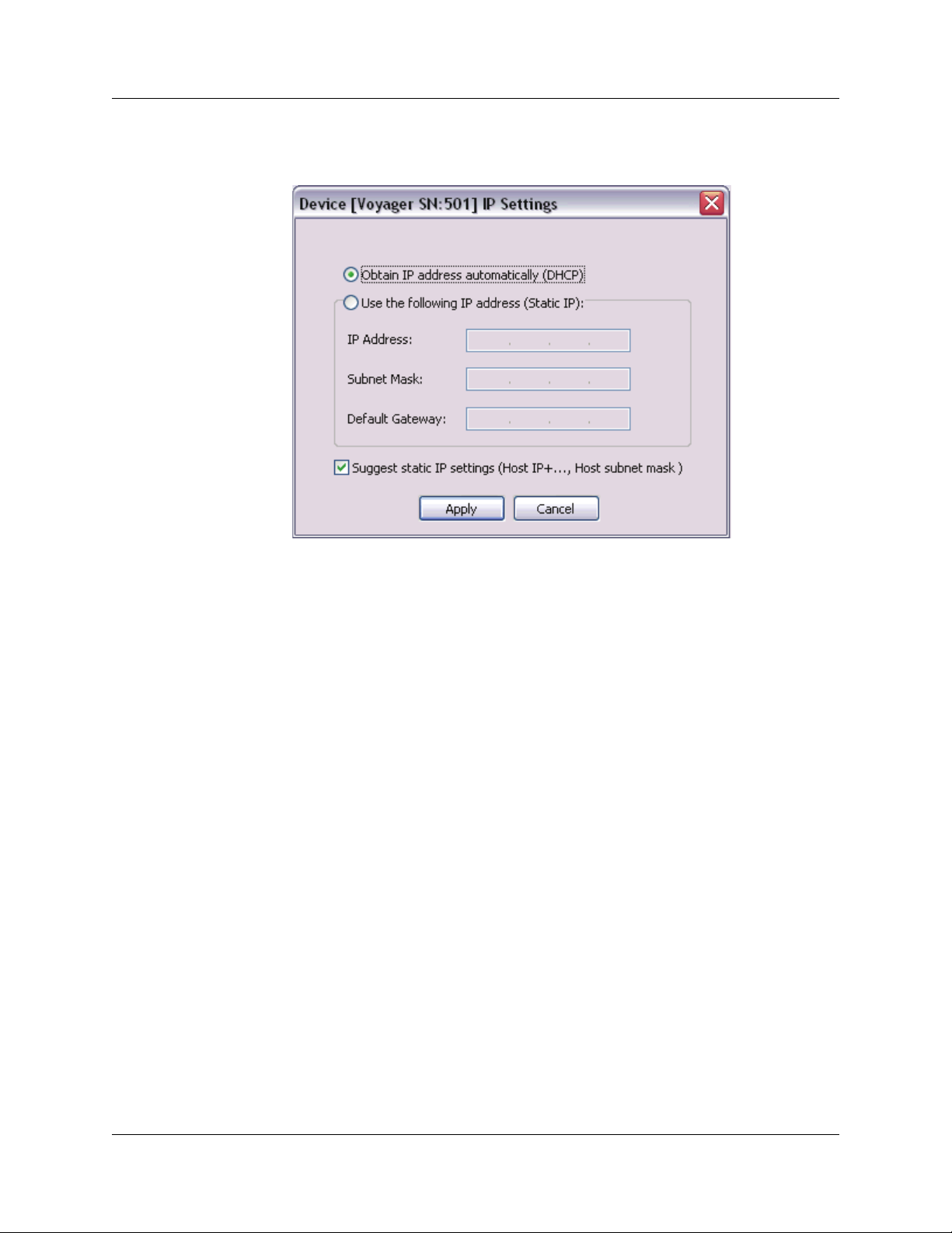
USB Protocol Suite User Manual Chapter 3: Installation
Step 2 Select the device to use in the recording, then click the IP Settings button to
display the Device IP Settings dialog.
Two radio buttons are available:
• Obtain IP address automatically (DHCP) [default]
• Use the following IP Address (Static IP)
LeCroy Corporation 59
Page 74

Chapter 3: Installation USB Protocol Suite User Manual
Step 3 To change to Static IP, click the Static IP radio button.
Enter the IP Address.
Enter the Subnet Mask.
Enter the Default Gateway.
Click Apply to get a success message and return to the Analyzer Devices
dialog.
Note: You can let the system Suggest static IP settings (IP address and
subnet mask).
Step 4 Click Close to close the dialog and use the device with a Static IP address.
60 LeCroy Corporation
Page 75

USB Protocol Suite User Manual Chapter 3: Installation
3.5.4 Analyzer Network
For Ethernet, to display the computers and analyzers on the local network, select
Setup > Analyzer Network to display the Analyzer Network dialog.
The dialog displays the computers on the network and the Analyzer devices connected
to the computers.
You can click Add to display the Add Analyzer Network Node dialog, in which you can
select a computer on the network
You can also Remove a selected computer or Reconnect a selected computer.
LeCroy Corporation 61
Page 76

Chapter 3: Installation USB Protocol Suite User Manual
3.5.5 USB 3.0 Device/Host Signal Parameters
For USB, to add, remove, edit, load (from a comma-delimited .csv file), or save (as a
comma-delimited .csv file) USB 3.0 devices and to calibrate USB 3.0 connections, select
Setup > USB 3.0 Device/Host Signal Parameters to display the
USB3 Device -> Analyzer -> Host Signal Profiles dialog.
The dialog lists the Device Name, Device Cable, Host Name, Host Cable, and to what
the Profile Signal Settings apply. It also shows Device-to-Analyzer and Host-to-Analyzer
custom signal settings.
62 LeCroy Corporation
Page 77

USB Protocol Suite User Manual Chapter 3: Installation
To add a device, click Add to display the USB3 Device -> Analyzer ->
Host Signal Parameter Profiles dialog.
The dialog allows you to Set Device “Current” or Read from Analyzer.
The dialog allows you to Set Host “Current” or Apply to Analyzer.
You can enter Device to Analyzer Signal Settings:
• Device Name
• Device Cable ID
• Input Signal Equalization (ISE) Settings: Short, medium and long time
constant (Current, Off, Minimum, Moderate, or Maximum)
• Pre-Emphasis Settings: Short and long time level (0 to 15) and
short and long time decay (0 to 7)
• Output Power Level: Current, or 213 mV to 1294 mV
You can enter Host to Analyzer Signal Settings:
•Host Name
• Host Cable ID
• Input Signal Equalization (ISE) Settings: Short, medium and long time
constant (Current, Off, Minimum, Moderate, or Maximum)
• Pre-Emphasis Settings: Short and long time level (0 to 15) and
short and long time decay (0 to 7)
• Output Power Level: Current, or 213 mV to 1294 mV
You can also Load the default settings or Load the last applied settings.
LeCroy Corporation 63
Page 78

Chapter 3: Installation USB Protocol Suite User Manual
Input Equalization
Depending on the hardware version of your system, there are two ways to control input
equalization. One method requires you to set three time constants, or use the defaults.
The other method allows you to select either Hi or Low, or use the default. The method
appropriate for your connected hardware is enabled.
For advanced users only: You can change the values for the “other hardware” by
checking Enable Both Eq modifications. For example, you might want to do this if you
use the same file for both Advisor T3 and Voyager M3i.
3.5.6 USB 3.0 Cabling and Signal Integrity
The Analyzer requires two connector discontinuities. In addition, bus-powered devices
are susceptible to voltage drops on VBus.
To maintain the best possible signal integrity for all devices under test, use high-quality
cabling and use the shortest possible cable lengths. Do not "stress" the system by using
long or low-quality cabling that might result in signal degradation.
If you suspect signal integrity problems in capture situations, you should first try using
shorter and higher-quality cables to see if this rectifies the problem.
64 LeCroy Corporation
Page 79

USB Protocol Suite User Manual Chapter 3: Installation
3.6 Your First USB Recording
After installing and launching the software, you can test the system by performing the
following steps:
Step 1 Connect a USB cable to each of the two connectors on the Analyzer module,
then connect the other ends to the USB device under test and USB host system.
Note: Whenever you do connect/disconnect testing, always plug/unplug the “B”
connector on the Analyzer, to insure that the Host detects the event properly. In
some cases, using the “A” port for this purpose can cause the Host to
misinterpret the terminations.
Step 2 Select Setup > Recording Options on the Menu Bar.
Step 3 Select the General tab to display a dialog box showing factory default settings,
such as Snapshot and 4 MB buffer size. For the first recording, you can leave
these settings unchanged. Under Recording Channels, select 2.0 to record
USB 2.0 traffic.
Note: Items not supported on your hardware are grayed out or not shown.
Step 4 Click OK to activate the recording options you selected.
Step 5 Turn on the USB devices that are to be tested and cause them to generate USB
traffic.
LeCroy Corporation 65
Page 80

Chapter 3: Installation USB Protocol Suite User Manual
Step 6 Click on the Tool Bar.
The system starts to record the USB traffic immediately. After 4 MB of traffic are
recorded, the Analyzer uploads the data and displays the packets in the trace
window.
Step 7 To terminate recording before the snapshot automatically completes,
click on the Tool Bar.
When the recording session finishes, the traffic uploads from the Analyzer to the
hard drive on your PC as a file named data.usb or the name you assigned as the
default filename. While the file is uploading, you should see a brown progress bar
at the bottom of the screen. When the bar disappears, the data has uploaded to
disk.
Step 8 To save a current recording for future reference, select File > Save As on the
Menu Bar.
OR
Click on the Tool Bar to display the standard Save As window.
Give the recording a unique name and save it to the appropriate directory.
66 LeCroy Corporation
Page 81

USB Protocol Suite User Manual Chapter 3: Installation
3.6.1 Trace View Features
After the recording terminates, the results display.
• The packet view display uses color and graphics to document captured traffic.
• Packets are on separate rows, with individual fields both labeled and
color-coded.
• Packets are numbered sequentially (as recorded), time-stamped (with a
resolution of 2 ns on 3.0 signalling), and highlighted to show the transmitted
speed (low-speed, full-speed, high-speed, or superspeed).
• You can name and save display formats for later use.
• Data fields can collapse to occupy minimal space in the display.
You can start the application from the Desktop or from the installed directory.
The display software can operate independently of the Analyzer. When used without the
Analyzer, the program functions in a Trace Viewer mode to view, analyze, and print
captured protocol traffic. When used with the Analyzer, you can set trigger conditions,
record, monitor, and analyze the activity of your USB bus.
LeCroy Corporation 67
Page 82

Chapter 3: Installation USB Protocol Suite User Manual
3.7 Notes on Vista and Windows 7 Directory Protections
3.7.1 User Data File Paths
Windows™ Vista and Windows 7 institute a policy which prevents user data from being
written into the Program Files directory/folder. It was common for applications written for
Windows XP (and earlier) to use the Program Files folder to store user data. LeCroy and
CATC products used this folder as a default folder for storing trace files, user option files
(default.opt, default.rec), scripts, and so on. The default folder for USB Protocol Suite
was:
x:\Program Files\Lecroy\USB Protocol Suite\…
Windows Vista and Windows 7 make such paths illegal directories for user data. For
Windows Vista and Windows 7, files that are accessible by different user accounts must
be in the path
x:\Users\Public\…
To preserve the ability of multiple user accounts to access all the LeCroy files that were
accessible in Windows XP when using Windows Vista and Windows 7, files that were in
the Program Files path in Windows XP are now in:
x:\Users\Public\Documents\Lecroy\USB Protocol Suite\…
In some cases, such as paths stored in the Recording Options .rec file, the application
silently changes this path, so that the Windows Vista and Windows 7 operating systems
will accept it as valid.
USB Protocol Suite on Windows XP still uses the Program Files directory. However, if a
Recording Options file that was created on a Windows 7 system is used on a
Windows XP system, trace files will be probably be recorded to a new Windows XP
directory called
x:\Users\Public\Documents\Lecroy\USB Protocol Suite\…
This is a legitimate path on a Windows XP system, so there are no conflicts with the
operating system.
68 LeCroy Corporation
Page 83
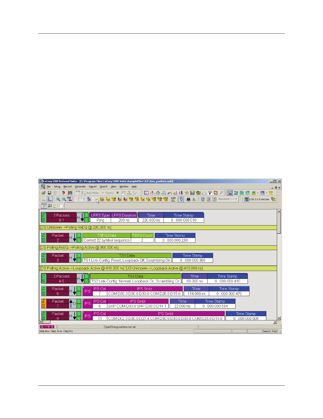
USB Protocol Suite User Manual Chapter 4: Software Overview
Chapter 4: Software Overview
The USB Protocol Suite application can function with or without the Analyzer. When used
without an Analyzer, the program functions in a Trace Viewer mode to view, analyze, and
print captured protocol traffic. The software also allows you to view trace files created by
the LeCroy USB Chief™, USB Advisor™, USB Detective™, USB Inspector™, and
USB Tracer™/Trainer™. Opening a file created with any of those Analyzers displays a
screen asking if you want to convert the old file to the new format under the name
<filename>_convert.usb.
When used with the Analyzer attached to the computer, you can monitor and analyze the
activity of your USB branch from USB ports on the Analyzer front.
4.1 Starting the Program
To start the USB Protocol Suite application:
Step 1 Select Start > Programs > LeCroy > USB Protocol Suite >
USB Protocol Suite.
LeCroy Corporation 69
Page 84

Chapter 4: Software Overview USB Protocol Suite User Manual
4.2 The Main Display Window
Menu Function
File
N
ew .utg file. Creates a new, empty traffic generation file. Available only if a trace
file (.usb) is open. To edit a .utg file, click Edit as Text in the toolbar.
Open Opens a file.
C
lose Closes the current file.
Save As Saves all, or a range of, packets from the current file.
P
rint Prints part or all of the current traffic data file.
Print Prev
Print Setup Sets the options for the current or new printer.
Ed
Edit Comment Creates or edits the Trace file comment field.
Check Syntax of .u
file
Export>>
Packets to Text
(Packet View Format)
Packets to .CSV
(Comma Separated
Values for Excel, etc.)
Format)
Packets to Host Traffic
Generator Text File
(.utg)
Packets to Device
Emulation Traffic
Generation Text File
(.utg)
Packets to USB3
Exerciser Script
(.usb3g)
Data
Merge Trace Files Merges two simultaneously recorded files into a single file. (This
mport If you have exported simulations to a defined .csv format, you can
I
Com
Data
Ex
iew Produces an on-screen preview before printing.
it as Text Opens the Script Editor. Available only when a traffic generation file
(.utg) is open. See “Editing a Generation File” on page 286.
See “Edit Comment” on page 124.
tg
Reads open .utg file and checks syntax for errors. Available only
when a traffic generation file (.utg) is open.
Saves all or part of a trace to a text file or generator file.
Saves trace as a text file in Packet View Format.
Saves trace as a comma-separated-values text file for use with
Microsoft
Saves trace as a script file that can be used by a Generator to
generate a trace. See “Exporting to USB 2.0 Generation Files (.utg
files)” on page 77.
Exports packets to Device Emulation files. This option does not
export transactions. See “Exporting to USB 2.0 Generation Files
(.utg files)” on page 77.
Exports packets to USB3 Exerciser Script files. This option does not
export transactions.
Exports Transfer data as a text or binary file.
command does not work if the files were recorded at different times).
import data from the .csv file to a BusEngine™ data file. To use this
feature, you must contact support for information on how to export to
a specific-format .csv file and then import the file.
pare Endpoint
it Exits the program.
Allows you to select two endpoints of different directions with the
same address and verify that the data OUT/IN is identical to the data
IN/OUT from the other endpoint. Used when running echo-types of
tests for data integrity. Available only when a trace file (.usb) is
open. (2.0 only)
®
Excel. See “Exports to .CSV” on page 76.
70 LeCroy Corporation
Page 85

USB Protocol Suite User Manual Chapter 4: Software Overview
Menu Function
Setup
Display Options Provides display options such as color, formats, and filters.
See “Display Options” on page 143.
Recording Options Provides setup options for recording, triggering events and filtering.
See “Recording Options” on page 221.
Update Device Updates the BusEngine™ and Firmware manually.
See “Manual Updates to Firmware, BusEngine, and
Serdes BusEngine” on page 350.
Launch CrossSync
Control Panel
Analyzer Network Opens a dialog box for browsing to local and networked analyzers.
All Connected
evices
D
USB 3.0 Device/
ignal
Host S
parameters
Record (see “Recording Status” on page 86.)
Start Causes the Analyzer to begin recording USB activity.
Stop
U
pload Again Allows you to upload a different portion of the captured trace if the
Reset SuperSpeed
Capture Engine
enerate (see “Traffic Generation (2.0)” on page 277)
G
S
tart/Stop
Opens the CrossSync multiple-analyzer traffic synchronization
software (see CrossSync Control Panel on page 90). For more
infoemation, refer to the CrossSync User Manual.
Within the dialog, click Add to browse. The dialog lists PCs that are
on the LAN. If a PC has an analyzer attached to it, and if DCOM
permissions have been set on the selected PC, clicking Select
establishes a connection.
See “Analyzer Network” on page 61.
Opens a dialog box with a list of analyzers connected to the host PC.
Lets you select an analyzer and update the BusEngine, Firmware,
and licensing information.
See “Analyzer Devices” on page 57.
Adds, removes, edits, loads, and saves USB 3.0 devices and lists
the device name, device cable, host name, host cable, and to what
the Profile Signal Settings apply.
Used to calibrate 3.0 connections. Also shows custom
device-to-analyzer and host-to-analyzer signal settings.
See “USB 3.0 Device/Host Signal Parameters” on page 62.
Causes the Analyzer to stop recording.
previous upload was only partially uploaded.
For USB 3.0 traffic capture, in some cases, the Analyzer might not
correctly lock onto the 5-GBps signals on power up, or it may unlock
after a long period of usage. To issue a soft reset to the SuperSpeed
capture engine, select this command. Note: After performing the
reset, you must retrain the link on your devices.
Starts traffic generation. After traffic generation has begun, the Start
command becomes Stop and lets you stop traffic generation.
ntelliFrame
I
Generation Mode
itstream Generation
B
Mode
LeCroy Corporation 71
Sets the mode of generation to IntelliFrame. Use before Start.
(2.0 only)
Sets the mode of generation to bitstream. Use before Start.
(2.0 only)
Page 86

Chapter 4: Software Overview USB Protocol Suite User Manual
Menu Function
Repeat Mode
port
Re
F
ile Information Displays information about the recording, such as the number of
Error Summary Summarizes the errors throughout the recording. Allows for fast
Timing Calculations Calculates timing between two packets and bus utilization.
Data View Shows packet information.
T
raffic Summary Summarizes the numbers and types of errors, packets, transactions,
Bus Utilization Displays graphs of packet length, bus usage, and bus usage by
Link Tracker Opens a window for displaying a detailed chronological view of
Navigator Allows you to view the location of errors and triggers in a
Allows you to repeat once, a specified number of times, or an infinite
number of times using the Generation Repeat Mode window.
(2.0 only)
packets and triggering setup.
See “File Information” on page 177.
navigation to packets with errors.
See “Error Summary” on page 179.
See “Timing Calculations” on page 180.
See “Detail View” on page 205.
split transactions, and transfers that occurred in the open trace.
See “Traffic Summary” on page 184.
device.
See “Bus Utilization” on page 186.
traffic. The window provides view and navigation options.
See “Link Tracker (3.0)” on page 193.
trace, narrow the range of traffic on display, and jump to any
point in the trace.
See “Using the Trace Navigator” on page 198.
Detail View Displays details of selected packet.
See “Detail View” on page 205.
S
pec View Shows packet header information and other items, in a view that
matches the USB 3.0 specification.
See “Spec View (3.0)” on page 206.
USB3 Link State
Timing View
Graphically shows how much time the link spends in each link
state.
See “USB3 Link State Timing View” on page 207.
USB3 LTSSM view Displays the LTSSM diagram depicted in the USB 3.0 specification.
See “USB3 LTSSM View” on page 209.
Power Tracker Displays voltage, current, and power.
See “Power Tracker” on page 210.
Run Verification
Scripts
Opens a window to allow you to run verification scripts over the
open trace.
See “Running Verification Scripts” on page 212.
72 LeCroy Corporation
Page 87

USB Protocol Suite User Manual Chapter 4: Software Overview
Menu Function
Search (see “Searching Traces” on page 125)
Go to T
rigger Positions the display to show the first packet that follows the trigger
event.
Go to Packet/
Transaction/Transfer
Go to M
G
Go to USB3.0» Positions the display to the selected event, condition, value, or type.
Go to SCSI Positions the display to the selected
arker » Positions the display to the selected marked packet.
o to USB2.0» Positions the display to the selected event, condition, value, or type.
Positions the display to the packet/transaction/transfer number
selected in the Go to P
acket/Transaction/Transfer menu.
SCSI Operation,
Command Status, Task Management, Task
Management Response, or Error.
Find Allows complex searches on multiple criteria.
See “Find” on page 138.
Find Next Repeats the previous Find operation.
S
earch Direction Allows the search direction to be changed from Forward to
Backward, or vice versa.
View
T
oolbars Displays list of available toolbars.
See “Resetting the Toolbar” on page 83.
Analyzer Network
Chat Bar
Status Bar Switches display of the Status Bar on or off.
QuickTiming Bar
Opens a dialog that allows you to conduct chat sessions over an IP
LAN. In order to send and receive electronic text messages, each
user must be working with a PC that is on an IP LAN and also
attached to an analyzer.
See “Status Bar” on page 85.
Quick Timing provides immediate time deltas and bandwidth
calculations. If the Start is placed on a packet that contains an
Address and Endpoint, the bandwidth for that combination is
displayed in the Status Bar below the trace data.
See “Set or Clear Quick Timing Markers” on page 97.
Real-time Statistics Allows you to view traffic statistics as they occur.
See “Real Time Monitoring” on page 217.
USB Electrical Test Tests electrical characteristics.
See “USB 3.0 Electrical Test Modes” on page 330.
Trace Views Displays CATC Trace, Compressed CATC Trace,
Spreadsheet (Color), or Spreadsheet (B/W).
Unhide cells Unhide Filtered Traffic, VBus Power, or Unhide All.
Zoom I
n Increases the size of the displayed elements.
Zoom O
Wrap Wraps displayed packets within the window.
Show USB 2
Only
Show USB 3 Traffic
Only
ut Decreases the size of the displayed elements.
Traffic
Displays only USB 2.0 traffic.
Displays only USB 3.0 traffic.
LeCroy Corporation 73
Page 88

Chapter 4: Software Overview USB Protocol Suite User Manual
Menu Function
Hiding USB 2 Traffic Hides.
•SOF’s: Start of Frames
•NAK
’s: NAK’ed Transactions
•D
evices: Packets belonging to specified devices by
address and endpoint
•C
hirps: Chirp-K and Chirp-J Bus conditions (these are
recorded only)
Hiding USB 3 Traffic Hides:
• Link Commands (Flow Control)
• Link Training Sequences (TS1, TS2, TSEQ)
• Logical Idle Packets
• Upstream Packets
• Downstream Packets
• Skip Sequences
• ISO Time Stamp Packets
• Inter-Packet Symbols
• Link Commands (Other than Flow Control)
• LMP Packets
• Electrical Idles
• LFPS Packets
• LTSSM Transition Indicators
View Layers Mode Display All Layers, Application Layers, or Lower USB Layers.
Stacking View Puts a group of packets in one row, to shorten display.
Apply
Decoding
Scripts
acket Level Displays Packets.
P
Tr
ansaction Level Displays Transactions.
Split Transaction Level Displays Split Transactions.
Tran
sfer Level Displays Transfers.
WA Group H
PTP Group PTP Transaction Level displays PTP Transactions
SCSI Operation Level Displays SCSI Operation Level
Decoding scripts set the values of the display and recording options
for optimum views of trace information from specific vendors or
classes of data. This menu option allows you to select the vendor or
class of data for the request recipients and endpoints listed in the
Request Recipients and Endpoints menu. You can keep the settings
across recordings.
See “Decode Requests” on page 155.
WA Segment Level displays Host Wire Adapter Segments.
HWA Transfer Level displays Host Wire Adapter Transfers.
D
WA Segment Level displays Device Wire Adapter Segments.
D
WA Transfer Level displays Device Wire Adapter Transfers.
PTP O
bject Transfer Level displays PTP Objects
ession Level displays PTP Sessions
PTP S
74 LeCroy Corporation
Page 89

USB Protocol Suite User Manual Chapter 4: Software Overview
Menu Function
Refresh Decoding Forces the software to re-decode transactions and transfers. Useful
if you have applied a decoding mapping which helps fully decode a
sequence of transfers, as is the case with Mass Storage decoding.
Window
New Window Switches display of the Tool Bar on or off.
C
ascade Displays all open windows in an overlapping arrangement.
Tile H
orizontal Displays all open windows in a above-below arrangement.
ertical Displays all open windows in a side-by-side arrangement.
Tile V
rrange Icons Arranges minimized windows at the bottom of the display.
A
Windows ... Displays a list of open windows.
elp
H
He
lp Displays online help. You can also select F1.
Video Tutorials Has links to YouTube videos that describe Voyager features:
Basic USB 3.0 Recording,
USB 3.0 Basic Triggering,
USB 3.0 Advanced Triggering,
Troubleshooting USB 3.0 Connection Issues,
USB 3.0 Packet Header Display,
USB 3.0 Compliance (Part 1).
USB 3.0 Compliance (Part 2)
pdate License Opens a dialog box for updating your LeCroy license.
U
See “Updating the Software License” on page 352.
D
isplay License
Information
Register Product
Online
Check for Updates Use the Internet to analyze your system for licensed updates. You
bout Displays version information about the Voyager M3 and the
A
Displays information related to licensing.
See “License Information” on page 351.
Register at the LeCroy website.
See “Registering Online” on page 352.
can set the system to automatically check for updates at application
startup in the LeCroy USB Protocol Suite Software Update window.
See “Software Updates” on page 346.
USB Protocol Suite.
See “Software, Firmware, and BusEngine Revisions” on page 345.
LeCroy Corporation 75
Page 90

Chapter 4: Software Overview USB Protocol Suite User Manual
4.2.1 Exports to .CSV
.CSV files may be created as exports from the contents of 2.0 CATC Trace Packet and
Transaction Views, 3.0 CATC Trace Packet views, and any Spreadsheet view. The output
is limited to 1 million rows.
4.2.1.2 Export Packets to .CSV
When viewing 2.0 or 3.0 Packets in either the CATC Trace view or the CATC Trace
Compressed view, selecting Export > Packets to .CSV <show
Packets/Transactions/Spreadsheet item from the Export> menu in a graphic>
exports the packets to a .csv file in a pre-configured format. The first row of that .csv file
shows what each column represents.
4.2.1.2 Export Transactions to .CSV
When viewing 2.0 Packets in either the CATC Trace view or the CATC Trace
Compressed view, selecting Export > Transactions to .CSV exports the 2.0
transactions to a .csv file in a pre-configured format. The first row of that .csv file shows
what each column represents.
4.2.1.2 Export Spreadsheet View to .CSV
When viewing 2.0 Packets in either the Black and White or Colored Spreadsheet Views
Trace view, selecting Export > Spreadsheet to .CSV exports the contents of the
spreadsheet to a .csv file in a pre-configured format. The columns match the columns as
you have defined them in your Spreadsheet view.
76 LeCroy Corporation
Page 91

USB Protocol Suite User Manual Chapter 4: Software Overview
4.2.2 Exporting to USB 2.0 Generation Files (.utg files)
Before exporting to a .utg file, first make sure the .usb file contains traffic for only one
device:
Step 1 Hide all other device addresses in the trace, leaving only the address of your
device and the Address 0 (the default enumeration address.)
Step 2 Save to a new file using the All and
Do not save hidden Packets/Transactions/Transfers selections.
Step 3 On the new file, you can now
Export… Packets to USB 2.0 … Text File (.utg) …
Step 4 If the captured file was Hi Speed and was recorded in Auto-Speed Detect mode,
you must add a ping=here statement before the first SOF packets in the .utg file.
This is required because, when the capture is made in Auto-Speed Detect mode,
the first "Ping" sequence is not captured in the trace file.
LeCroy Corporation 77
Page 92

Chapter 4: Software Overview USB Protocol Suite User Manual
4.3 Tool Bar
The Tool Bar provides quick and convenient access to the most popular program
functions. Tool tips briefly describe the functionality of each icon and menu item as the
mouse arrow is moved over the icon/item.
4.3.1 Files, Searches, and Options
Open file Find (see “Find” on page 138)
Save As Find Next
Setup Recording Options. See
Edit as Text
“Recording Options” on page 221.
4.3.2 Zoom and Wrap
Zoom In Zoom Out
Setup Display Options
See “Display Options” on page 143.
Wrap
78 LeCroy Corporation
Page 93

USB Protocol Suite User Manual Chapter 4: Software Overview
4.3.3 Miscellaneous
Display Realtime Statistics. See
“Real Time Monitoring” on page 217.
Assign High Level Decodes.
See “Decode Requests” on
page 155.
Display Stacking View.
Stacking conserves space in the trace view by displaying repeating
items (or item groups) as one item, along with the number of repeats.
For USB 2.0, stacking items (or item groups) can be:
•SOF
• Chirp (merges J's and Ks into one stacked display unit)
• NAK'ed (split) Transaction
For USB 3.0, stacking items (or item groups) can be:
• TSEQ
• TS1 with same Link Functionality
• TS2 with same Link Functionality
• LFPS with same Type
•LUP
•LDN
• NAK'ed Transaction
Note: Items are grouped regardless of any intervening Skip
Sequence, Electrical Idle, or Logical Idle symbols. If any of these
occur during a stream of the repeating stacking item, they are not
displayed.
LeCroy Corporation 79
Page 94

Chapter 4: Software Overview USB Protocol Suite User Manual
4.3.4 Analysis (Reports)
File Information Report
See “File Information” on page 177.
Timing and Bus Usage Calculations
See “Timing Calculations” on page
180.
Data View
See “Detail View” on page 205.
Link Tracker
See “Link Tracker (3.0)” on page
193.
Open the Navigator bar
See “Using the Trace Navigator” on
page 198.
Show USB3 Link State Timing View.
See “USB3 Link State Timing
View” on page 207.
Run Verification Scripts.
See “Running Verification Scripts” on
page 212.
Error Report
See “Error Summary” on page 179.
Traffic Summary
See “Traffic Summary” on page 184.
Bus Utilization
See “Bus Utilization” on page 186.
Spec View
See “Spec View (3.0)” on page 206.
Detail View
See “Detail View” on page 205.
Show USB3 LTSSM View
See “USB3 LTSSM View” on
page 209.
Show Power Tracker.
(Power captures are supported only
on Voyager M3i.)
See “Power Tracker” on page 210.
4.3.5 Recording
Superspeed (USB 3.0) receiver terminations of Analyzer:
M3i: If both Analyzer ports are set to Auto in Recording Options, this button
M3: This button is always enabled, and Auto mode is not supported.
Start Recording Manual Trigger
Stop Recording Repeat Upload
Momentary VBus Disconnect (Voyager M3i Only)
Causes the VBus power between the Host and the Device connected through
the Analyzer A and B USB ports to be broken for 1 second, simulating a
unplug-plugin cycle. This is the recommended method of creating plug-in
scenarios.
Note: When Disconnect is done during recording, it may cause capturing of IPS
(undecodable symbols) and false triggering of CRC triggers, because packets
will be abruptly stopped in the middle of a symbol stream.
is dimmed. If either port is set to Manual, this button can apply or
remove USB 3.0 termination.
80 LeCroy Corporation
Page 95

USB Protocol Suite User Manual Chapter 4: Software Overview
4.3.6 Generator (Traffic Generation for USB 3)
(See “Traffic Generation (3.0 Exerciser)” on page 307)
Go to
U S B 3 . 0
Exerciser
window.
Display
Export to
Script dialog.
Manual Trigger
Repeat Upload
4.3.7 Generator (Traffic Generation for USB 2)
(See “Traffic Generation (2.0)” on page 277)
Start or Stop Traffic Generation
(available if you have the
Traffic Generation module).
Bitstream and Intelliframe modes
Repeat Mode. This button becomes active
when a traffic generation file (*.utg) is
open.
4.3.8 View Level
(See “Switch to Transactions View” on page 108 and following)
Display Packets
See “Trace View Features” on page
93.
Display Transactions
See “Switch to Transactions View”
on page 108.
Display Split Transactions
See “Switch to Split Transaction
View” on page 112.
Display Transfers
See “Switch to Transfer View” on
page 112.
Display Host Wire Adapter
Segments
See “Switch to Host Wire Adapter
Segment View” on page 115.
Display Host Wire Adapter Transfers
See “Switch to Host Wire Adapter
Transfer View” on page 116.
WA Group
Click the arrow to display the
Wire Adapter Levels.
Display Device Wire Adapter
Segments
See “Switch to Device Wire Adapter
Segment View” on page 116.
Display Device Wire Adapter
Transfers
See “Switch to Device Wire Adapter
Transfer View” on page 116.
Display PTP Transactions
See “Switch to PTP Transactions” on
page 117.
Display PTP Objects
See “Switch to PTP Object
Transfers” on page 117.
Display PTP Sessions
See “Switch to PTP Sessions” on
page 118.
Display SCSI Operations
PTP Group
Click the arrow to display the
PTP Levels
LeCroy Corporation 81
Page 96
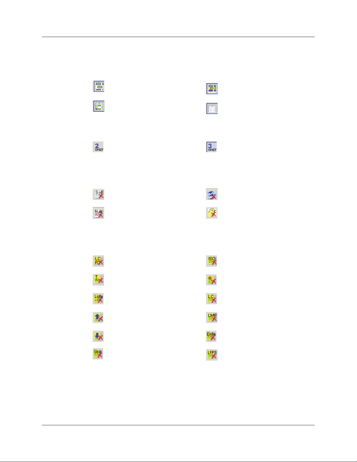
Chapter 4: Software Overview USB Protocol Suite User Manual
4.3.9 Trace Views
(See “Compressed CATC Trace View” on page 119 and “Spreadsheet View” on page
120)
Normal CATC Trace View Compressed CATC Trace
Spreadsheet View (Color) Spreadsheet View (B/W)
4.3.10 USB 2 USB 3 Show
Display USB 2.0 traffic only. Display USB 3.0 traffic only.
4.3.11 USB 2.0 Display/Hide
Hide SOFs. Hide Devices
4.3.12 USB 3.0 Display/Hide
4.4 Tooltips
Hide NAK’ed transactions. Hide Chirps
Hide Link Commands
(Flow Control).
Hide Link Training Sequences
(TS1, TS2, TSEQ).
Hide Logical Idle Packets.
Hide Upstream Packets. Hide LMP Packets.
Hide Downstream Packets. Hide Electrical Idles.
Hide Skip Sequences. Hide LFPS Packets.
Hide ISO Time Stamp Packets.
Hide Inter-Packet Symbols
(unexpected packets).
Hide Link Commands
(other than Flow Control).
Tooltips provide information about trace cells and application buttons. To display a tooltip,
position the mouse pointer over the item.
82 LeCroy Corporation
Page 97
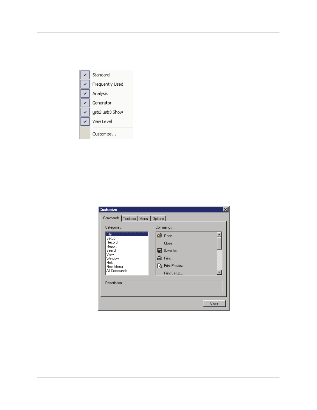
USB Protocol Suite User Manual Chapter 4: Software Overview
4.5 View Options
You can hide, display, or reset toolbars by selecting View > Tool bars from the menu bar.
4.5.1 Resetting the Toolbar
From time to time (such as following a software upgrade), it is possible for the buttons on
the toolbar not to match their intended function.
To reset the toolbar:
Step 1 Select View > Tool bars from the menu bar.
Step 2 Select Customize from the submenu to display the Customize dialog box.
LeCroy Corporation 83
Page 98
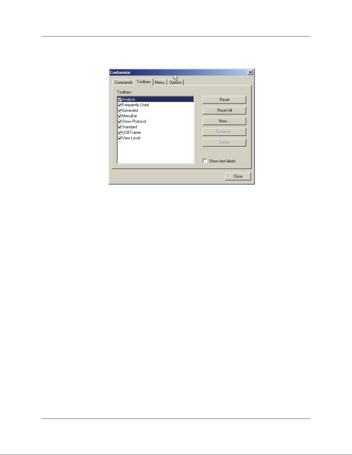
Chapter 4: Software Overview USB Protocol Suite User Manual
Step 3 Select the Toolbars tab to display the Toolbars page of the Customize dialog
box.
Step 4 Click the Reset All button.
The toolbar resets to the factory defaults.
84 LeCroy Corporation
Page 99
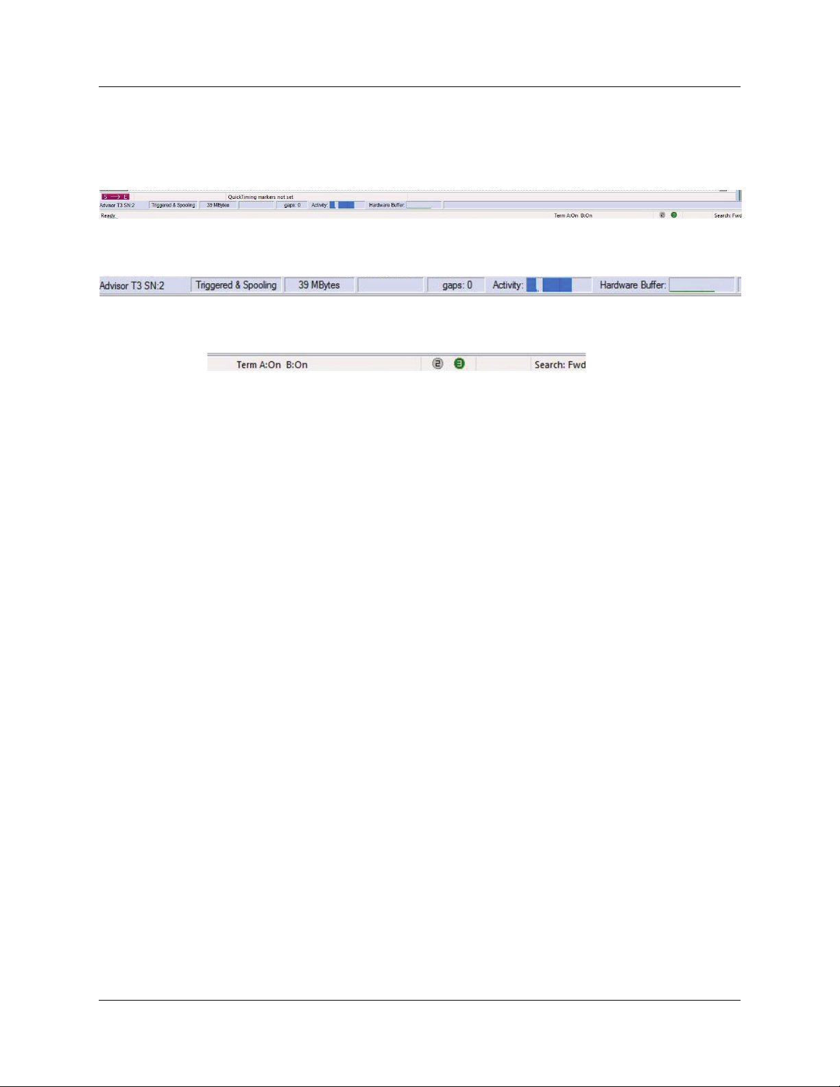
USB Protocol Suite User Manual Chapter 4: Software Overview
4.6 Status Bar
The Status Bar is located at the bottom of the main display window.
Depending on the current activity, the left side of the bar has segments that indicate the
hardware, status, size, activity, and buffer.
The right side of the bar has segments that indicate port status, link status, and
search direction.
4.6.1 Recording Progress
When you begin recording, the Status Bar displays an indicator.
As recording progresses, the indicator changes to reflect the recording progress
graphically:
A black vertical line illustrates the location of the Trigger Position that you selected in
Recording Options.
• Pre-Trigger progress is in the field to the left of the Trigger Position in the
before-trigger color specified in the Display Options.
• When the Trigger Position is reached, the indicator wiggles as it waits for the
trigger.
• After the trigger occurs, the field to the right of the Trigger Position fills with the
after-trigger color specified in the Display Options.
• When recording is complete, the upper half of the progress indicator fills with
white, indicating the progress of the data upload to the host computer.
You should be aware of two exceptional conditions:
• If a Trigger Event occurs during the before-trigger recording, the
before-trigger color changes to the after-trigger color to indicate that not all
the expected data was recorded pre-trigger.
• When you click Stop before or after a Trigger Event, the Status Bar adjusts
accordingly to begin uploading the most recently recorded data.
The indicator fills with color in proportion to the specified size and actual rate at which the
hardware is writing and reading the recording memory. However, the indicator is
normalized to fill the space within the Status Bar.
LeCroy Corporation 85
Page 100

Chapter 4: Software Overview USB Protocol Suite User Manual
4.6.2 Recording Status
During recording, the current Recording Status is in a segment. When you activate the
Record function, this segment flashes a message depending on the selected
Recording Options, such as Triggered or Uploading.
After recording stops,
• The flashing message changes to Uploading data–x% done (x% indicates
the percentage completion of the data uploading process).
• The traffic data copies to disk (overwriting any previous version of this file)
using the default file name data.usb. You can also create a file name by
specifying one in the Recording Options dialog box.
To abort the upload process:
• Press Esc on the keyboard
OR
• Again click in the Tool Bar.
You are asked if you want to keep or discard the partially uploaded data.
Note: While uploading is in progress, clicking the Stop button again opens a dialog
that allows you to do a partial upload, flush the current file, keep what has
uploaded at this point, or to continue uploading.
The Partial Upload button enables when you have partially uploaded data. When you
click Partial Upload, a dialog box displays options on what portion of data you want to
upload again.
86 LeCroy Corporation
 Loading...