

Page 1

2403 Walsh Avenue, Santa Clara, CA 95051-1302 Tel: +1/408.727.6600 Fax: +1/408.727.6622
CATC Request Definition (.req)
and Descriptor Definition (.dsc)
Files Reference Manual
October 16, 2001
Page 2

COMPUTER ACCESS TECHNOLOGY CORPORATION
CATC Request Definition (.req) and Descriptor
Definition (.dsc) Files Reference Manual
Document Disclaimer
The information contained in this document has been carefully checked and is
believed to be reliable. However, no responsibility can be assumed for inaccuracies
that may not have been detected.
CATC reserves the right to revise the information presented in this document
without notice or penalty.
Trademarks and Servicemarks
CATC is a trademark of Computer Access Technology Corporation.
All other trademarks are property of their respective companies.
Copyright
Copyright 2001, Computer Access Technology Corporation (CATC). All rights
reserved.
This document may be printed and reproduced without additional permission, but
all copies should contain this copyright notice.
ii
Page 3

COMPUTER ACCESS TECHNOLOGY CORPORATION USB REQUEST DEFINITION (.REQ) FILES
Reference Manual
TABLE OF CONTENTS
USB Request Definition (.req) Files . . . . . . . . . . 1
Structure. . . . . . . . . . . . . . . . . . . . . . . . . . . . . . . . . . . . . . . . . . 1
Entries. . . . . . . . . . . . . . . . . . . . . . . . . . . . . . . . . . . . . . . . . . . . 2
Defines . . . . . . . . . . . . . . . . . . . . . . . . . . . . . . . . . . . . . . . . . . . . . . . . . 2
GroupName. . . . . . . . . . . . . . . . . . . . . . . . . . . . . . . . . . . . . . . . . . . . . . 4
GroupType . . . . . . . . . . . . . . . . . . . . . . . . . . . . . . . . . . . . . . . . . . . . . . 4
GroupType=Standard . . . . . . . . . . . . . . . . . . . . . . . . . . . . . . . . . . . 4
GroupType=Class . . . . . . . . . . . . . . . . . . . . . . . . . . . . . . . . . . . . . . 4
GroupType=Vendor . . . . . . . . . . . . . . . . . . . . . . . . . . . . . . . . . . . . 5
AllRequests. . . . . . . . . . . . . . . . . . . . . . . . . . . . . . . . . . . . . . . . . . . . . . 5
Request(...) . . . . . . . . . . . . . . . . . . . . . . . . . . . . . . . . . . . . . . . . . . . . . . 5
EndpointData . . . . . . . . . . . . . . . . . . . . . . . . . . . . . . . . . . . . . . . . . . . . 6
Request definitions. . . . . . . . . . . . . . . . . . . . . . . . . . . . . . . . . . 6
Decoding Definition strings: wValue, wIndex, and Data . . . . . . . . . . . 7
WordValue . . . . . . . . . . . . . . . . . . . . . . . . . . . . . . . . . . . . . . . . . . . 7
FormatValue . . . . . . . . . . . . . . . . . . . . . . . . . . . . . . . . . . . . . . . . . . 8
Bitmap. . . . . . . . . . . . . . . . . . . . . . . . . . . . . . . . . . . . . . . . . . . . . . 11
Additional Request Keywords . . . . . . . . . . . . . . . . . . . . . . . 13
bmRequestType . . . . . . . . . . . . . . . . . . . . . . . . . . . . . . . . . . . . . . 13
Bytes(x, y). . . . . . . . . . . . . . . . . . . . . . . . . . . . . . . . . . . . . . . . . . . 13
Color(R,G,B) . . . . . . . . . . . . . . . . . . . . . . . . . . . . . . . . . . . . . . . . 13
Databytes(x, y) . . . . . . . . . . . . . . . . . . . . . . . . . . . . . . . . . . . . . . . 13
Depends(...). . . . . . . . . . . . . . . . . . . . . . . . . . . . . . . . . . . . . . . . . . 15
Descriptors . . . . . . . . . . . . . . . . . . . . . . . . . . . . . . . . . . . . . . . . . . 17
Endian . . . . . . . . . . . . . . . . . . . . . . . . . . . . . . . . . . . . . . . . . . . . . . 18
HIBYTE . . . . . . . . . . . . . . . . . . . . . . . . . . . . . . . . . . . . . . . . . . . . 18
Length . . . . . . . . . . . . . . . . . . . . . . . . . . . . . . . . . . . . . . . . . . . . . . 18
LOBYTE. . . . . . . . . . . . . . . . . . . . . . . . . . . . . . . . . . . . . . . . . . . . 19
Name. . . . . . . . . . . . . . . . . . . . . . . . . . . . . . . . . . . . . . . . . . . . . . . 19
EndpointData Definitions . . . . . . . . . . . . . . . . . . . . . . . . . . . 20
Caption . . . . . . . . . . . . . . . . . . . . . . . . . . . . . . . . . . . . . . . . . . . . . . . . 20
EndpointDirection. . . . . . . . . . . . . . . . . . . . . . . . . . . . . . . . . . . . . . . . 21
EndpointId . . . . . . . . . . . . . . . . . . . . . . . . . . . . . . . . . . . . . . . . . . . . . 21
EndpointType . . . . . . . . . . . . . . . . . . . . . . . . . . . . . . . . . . . . . . . . . . . 21
MaxPacketSize . . . . . . . . . . . . . . . . . . . . . . . . . . . . . . . . . . . . . . . . . . 22
MaxTransferSize. . . . . . . . . . . . . . . . . . . . . . . . . . . . . . . . . . . . . . . . . 22
i
Page 4

COMPUTER ACCESS TECHNOLOGY CORPORATION USB REQUEST DEFINITION (.REQ) FILES
Reference Manual
Nested Request Definitions . . . . . . . . . . . . . . . . . . . . . . . . . . 23
Comments . . . . . . . . . . . . . . . . . . . . . . . . . . . . . . . . . . . . . . . . 24
USB Descriptor Definition (.dsc) Files . . . . . . . 25
Structure. . . . . . . . . . . . . . . . . . . . . . . . . . . . . . . . . . . . . . . . . 25
Entries. . . . . . . . . . . . . . . . . . . . . . . . . . . . . . . . . . . . . . . . . . . 26
DescriptorName . . . . . . . . . . . . . . . . . . . . . . . . . . . . . . . . . . . . . . . . . 26
DescriptorType . . . . . . . . . . . . . . . . . . . . . . . . . . . . . . . . . . . . . . . . . . 26
DescriptorSubtype . . . . . . . . . . . . . . . . . . . . . . . . . . . . . . . . . . . . . . . 27
ClassCode . . . . . . . . . . . . . . . . . . . . . . . . . . . . . . . . . . . . . . . . . . . . . . 27
SubclassCode . . . . . . . . . . . . . . . . . . . . . . . . . . . . . . . . . . . . . . . . . . . 28
AllOffsets . . . . . . . . . . . . . . . . . . . . . . . . . . . . . . . . . . . . . . . . . . . . . . 28
Offset(...). . . . . . . . . . . . . . . . . . . . . . . . . . . . . . . . . . . . . . . . . . . . . . . 29
Descriptor definitions . . . . . . . . . . . . . . . . . . . . . . . . . . . . . . 29
Decoding Definition Strings . . . . . . . . . . . . . . . . . . . . . . . . . . . . . . . . 29
FormatValue, WordValue, and Bitmap . . . . . . . . . . . . . . . . . . . . 30
Additional Descriptor Keywords . . . . . . . . . . . . . . . . . . . . . 30
BCD . . . . . . . . . . . . . . . . . . . . . . . . . . . . . . . . . . . . . . . . . . . . . . . 30
Size . . . . . . . . . . . . . . . . . . . . . . . . . . . . . . . . . . . . . . . . . . . . . . . . 31
Units . . . . . . . . . . . . . . . . . . . . . . . . . . . . . . . . . . . . . . . . . . . . . . . 31
ii
Page 5

COMPUTER ACCESS TECHNOLOGY CORPORATION USB REQUEST DEFINITION (.REQ) FILES
Reference Manual
USB REQUEST DEFINITION (.req)
F
ILES
Request definition (.req) files are used to configure decoding of class- or vendorspecific data of any protocol defined for USB. A .req file is a set of instructions that
contains definitions that describe, in USB-specific terms, how to take blocks of data
and break them into fields with consecutive decoding of each field. The data being
decoded can be data in a USB Device Request, or any formatted data that is sent on
an Interrupt or Bulk endpoint of a USB device.
The request definition files are text-based files that are identifiable by their .req extension. Customized decoding of USB requests is possible by editing files or
creating new definition files. This document describes the components of a .req file
and the format for writing or editing a .req file.
Please refer to the Universal Serial Bus Specification, version 1.1 for details about
USB protocol. The USB specification is available from the USB Implementers
Forum (USB-IF) at http://www.usb.org/.
Structure
A .req file has the following basic structure:
[Defines=
{
<Define_0>=<Define_Name_0>
<Define_1>=<Define_Name_1>
<Define_2>=<Define_Name_2>
...
}]
opt
GroupName=<name>
GroupType=<Standard, Class, or Vendor>
AllRequests=
{
<bRequest_0>=<bRequest_Name_0>
<bRequest_1>=<bRequest_Name_1>
<bRequest_2>=<bRequest_Name_2>
...
}
1
Page 6

COMPUTER ACCESS TECHNOLOGY CORPORATION USB REQUEST DEFINITION (.REQ) FILES
Reference Manual
Request(<bRequest_0>)=
{
...
}
Request(<bRequest_1>)=
{
...
}
Request(<bRequest_2>)=
{
...
}
...
[EndpointData=
{
...
}]
opt
[EndpointData=
{
...
}]
opt
...
Entries
This section describes the basic entries that comprise a .req file.
Note: There must be no white space in between keywords and the equal sign (=) ;
for example: GroupName=. However, it is permissible to put white space
between values and the equal sign; e.g., GroupName= Class or
0x00 = RequestName. In the case of keywords that require parentheses fol-
lowed by an equal sign, there must not be white space on either side of the paren-
theses: Request(...)=.
Defines
The Defines keyword is an optional entry that is used to associate a numeric
value with a text string. Once the association is set up, those values can be referred
to by name in the request definitions. The Defines definition uses the following
format:
2
Page 7

COMPUTER ACCESS TECHNOLOGY CORPORATION USB REQUEST DEFINITION (.REQ) FILES
Reference Manual
Defines=
{
<value>=<string>
}
The value should be set to the actual value, while string represents the name
of the unit. An example is found in the sample file Audio.req:
DEFINES={
0x01=TERMINAL_UNIT
0x05=TERMINAL_UNIT
0x09=TERMINAL_UNIT
0x0C=TERMINAL_UNIT
0x02=PROCESSING_UNIT
0x03=PROCESSING_UNIT
0x04=FEATURE_UNIT
0x06=FEATURE_UNIT
0x08=FEATURE_UNIT
0x0B=FEATURE_UNIT
0x07=MIXER_UNIT
0x0A=MIXER_UNIT
}
These units can now be referred to by name, instead of by number, in the request
definitions:
wIndex={
HIBYTE={
Depends(HIBYTE(wIndex))={
TERMINAL_UNIT={
FormatValue=Terminal ID 0x%02X
}
MIXER_UNIT={
FormatValue=Mixer Unit ID 0x%02X
}
SELECTOR_UNIT={
FormatValue=Selector Unit ID 0x%02X
}
FEATURE_UNIT={
FormatValue=Feature Unit 0x%02X
}
PROCESSING_UNIT={
FormatValue=Processing Unit ID 0x%02X
}
3
Page 8
COMPUTER ACCESS TECHNOLOGY CORPORATION USB REQUEST DEFINITION (.REQ) FILES
Reference Manual
EXTENSION_UNIT={
FormatValue=Extension Unit ID 0x%02X
}
}
}
...
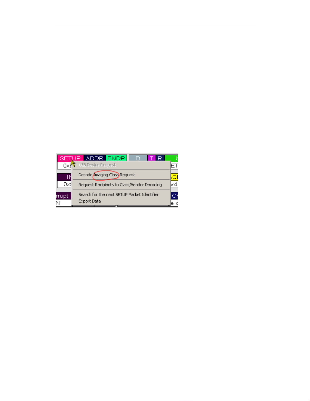
GroupName
The GroupName entry defines the name for the group of requests described in the
file. This name also appears in the SETUP field's request decoding context menu.
For example,
GroupName=Imaging Class
shows up in the context menu this way:
Figure 1: GroupName entry appears in SETUP context
menu
GroupType
The GroupType entry defines the type of requests in the file. There are three (3)
possible settings for the GroupType entry: GroupType=Standard,
GroupType=Class, and GroupType=Vendor.
GroupType=Standard
A set GroupType=Standard requests defines the standard USB requests. Note
that in the case of defining standard USB requests, there can be only one .req file.
CATC supplies the standard request definitions in the file standard.req.
GroupType=Class
GroupType=Class indicates that the file defines a set of class-specific USB
requests. This group type also requires a ClassCode entry, which specifies the
USB-assigned device class code. For example,
GroupType=Class
ClassCode=0x03
4
Page 9

COMPUTER ACCESS TECHNOLOGY CORPORATION USB REQUEST DEFINITION (.REQ) FILES
Reference Manual
defines the Human Interface Device (HID) class code.
GroupType=Vendor
GroupType=Vendor indicates that the file defines a set of vendor-specific USB
requests. This group type also requires VendorID and ProductID entries.
These values are used to uniquely identify the Vendor Decoding group when it is
associated with Request Recipients in a trace file. The value for VendorID is the
assigned vendor ID. The value for ProductID doesn't actually have to match the
real product ID for the device. For example:
GroupType=Vendor
VendorID=0x0423
ProductID=0x000D
AllRequests
The AllRequests keyword is used to specify the bRequest values for all of
the requests described in the .req file. The AllRequests definition uses the
following format:
AllRequests=
{
<bRequest>=<RequestNameString>
...
}
The value bRequest is is the USB-assigned value, and is represented numerically.
RequestNameString is the textual representation of bRequest. It also rep-
resents the name of the request that will appear in the Request Decoding dialog. For
example:
AllRequests=
{
0x00=REQUEST_NAME_0
0x01=REQUEST_NAME_1
}
Note: it's not necessary for the numeric bRequest values to start from zero or to
increase sequentially. In addition, the numeric values may be in decimal or hexadecimal.
Request(...)
Request(...) defines a request listed in the AllRequests entry. Request
definitions follow the format
5
Page 10

COMPUTER ACCESS TECHNOLOGY CORPORATION USB REQUEST DEFINITION (.REQ) FILES
Reference Manual
Request(<bRequest>)=
{
...
}
The bRequest value should match the numeric value assigned to the request in
the AllRequests entry. For example:
Request(0x00)=
{
...
}
Request(0x01)=
{
...
}
EndpointData
EndpointData defines endpoint data decoding.
The basic structure for an EndpointData definition is
EndpointData=
{
[Caption=<string>]
[EndpointType=<string>]
[EndpointDirection=IN or OUT]
[EndpointId=<value>]
opt
opt
opt
opt
MaxPacketSize=<integer>
MaxTransferSize=<integer>
Data=
{
...
}
}
For more information about EndpointData definitions, please see page 20.
Request definitions
The bulk of a .req file is composed of Request entries, which are the actual
request definitions. This section describes the contents and formatting of a
Request entry.
6
Page 11

COMPUTER ACCESS TECHNOLOGY CORPORATION USB REQUEST DEFINITION (.REQ) FILES
Reference Manual
Decoding Definition strings: wValue, wIndex, and Data
A request definition may contain three optional decoding definition strings:
wValue, wIndex, and Data. wValue and wIndex define how the wValue and
wIndex fields of the request are decoded. Data specifies how Data fields are
decoded during the request's data stage. All three use the same definition format, as
follows:
<wValue, wIndex or Data>=
{
...
}
If one or more of the definition strings is omitted, then the Request Decoding
applies default decoding.
The contents of the decoding definitions can be built using one or more of these
three basic keywords: WordValue, FormatValue, and Bitmap.
WordValue
Use the WordValue keyword when the field has a defined set of possible values,
and each value has a different meaning. The entries are formatted as an enumerated
list, as follows:
WordValue=
{
<wValue_0>=<Value_Meaning_0>
<wValue_1>=<Value_Meaning_1>
...
}
The possible values for wValue are represented numerically. The meanings are
generally represented as text strings. WordValue entries work similarly to if-then
statements: if wValue matches a wValue value in the WordValue list, then the
meaning will appear in the wValue trace field. If the value of wValue doesn't
match a value in the list, then, by default, its numeric value will be displayed in the
wValue trace field. However, this default can also be overridden with a different
type of decoding -- a FormatValue entry (see “FormatValue” on page 8 for
details) or a Bitmap entry (see “Bitmap” on page 11 for more details).
The following example comes from the wValue entry of the hub.req
SetFeature request definition. The figure shows the output that results when
wValue is 0x0008.
WordValue={
0x0001=PORT_ENABLE
0x0002=PORT_SUSPEND
7
Page 12

COMPUTER ACCESS TECHNOLOGY CORPORATION USB REQUEST DEFINITION (.REQ) FILES
Reference Manual
0x0003=PORT_OVER_CURRENT (Should not clear this
feature!)
0x0004=PORT_RESET (Should not clear this feature!)
0x0008=PORT_POWER
0x0009=PORT_LOW_SPEED (Should not clear this
feature!)
0x0010=C_PORT_CONNECTION
0x0011=C_PORT_ENABLE
0x0012=C_PORT_SUSPEND
0x0013=C_PORT_OVER_CURRENT
0x0014=C_PORT_RESET
}
Figure 2: Resulting trace output when wValue
for hub.req's SET_FEATURE is 0x0008
FormatValue
Use FormatValue to specify the output formatting of numeric values. A string
can be included in the decoding definition, too. This entry can also be used to
specify default behaviors. Formatting is controlled using standard C language
printf format conversion characters. The structure of FormatValue is
FormatValue=<string>
The conversion specification is contained within the string. The following example
is taken from the wIndex definition for SET_FEATURE in the hub.req file:
0x23={
FormatValue=Port # %I
}
Here is an example of possible output:
Figure 3: Resulting trace output for a FormatValue
definition
By changing the FormatValue definition as follows,
FormatValue=Cheese (0x%03x)
8
Page 13

COMPUTER ACCESS TECHNOLOGY CORPORATION USB REQUEST DEFINITION (.REQ) FILES
Reference Manual
the output changes to this:
Figure 4: Resulting trace output for the altered FormatValue
definition
A FormatValue entry can also be used somewhat like the 'else' portion of an if-
else statement to specify the formatting of default behaviors. To do this, place the
FormatValue entry inside the definition for which it will act as the default value.
If the request value matches a value that is specified in the definition, then the
meaning for that value will display in the trace field; otherwise, the FormatValue
default definition will be used. The following examples are taken from the sample
printer.req file. In the first example, from the GET_DEVICE_ID request definition,
there is no specified format for the default value of wValue:
wValue={
Depends(bmRequestType)={
0xA1={
FormatValue=Configuration Index is 0x%04X
}
}
}
Therefore, the default, unformatted trace output for the wValue field displays as
such:
Figure 5: Default trace
output with no formatting
specifications
However, when FormatValue is used to control its appearance, as in the
following example,
wValue={
Depends(bmRequestType)={
0xA1={
FormatValue=Configuration Index is 0x%04X
}
}
FormatValue=GET_DEVICE_ID default is %d
}
9
Page 14

COMPUTER ACCESS TECHNOLOGY CORPORATION USB REQUEST DEFINITION (.REQ) FILES
Reference Manual
these results can be achieved:
Figure 6: Default trace output with
formatting specifications
Format Conversion Characters
These are standard C language printf format conversion characters:
Code Type Output
c Integer Character
d Integer Signed decimal integer.
I Integer Signed decimal integer
u Integer Unsigned decimal integer
x Integer Unsigned hexadecimal integer, using “abcdef.”
X Integer Unsigned hexadecimal integer, using “ABCDEF.”
Table 1: Format conversion characters
A conversion specification begins with a percent sign (%) and ends with a conver-
sion character. The following optional items can be included, in order, between the
% and the conversion character to further control argument formatting:
• Flag characters: these are used to further specify the formatting. There are five flag
characters:
•A minus sign (-)will cause an argument to be left-aligned in its field. Without the
minus sign, the default position of the argument is right-aligned.
•A plus sign (+) will insert a plus sign before a positive signed integer. This only works
with the conversion characters d and i.
•A space will insert a space before a positive signed integer. This only works with the
conversion characters d and i. If both a space and a plus sign are used, the space flag
will be ignored.
•A hash mark (#) will prepend 0x or 0X to a hexadecimal number if used with x or X.
•A zero (0) will pad the field with zeros instead of with spaces.
• Field width specification: this is a positive integer that defines the field width, in spaces,
of the converted argument. If the number of characters in the argument is smaller than the
field width, then the field is padded with spaces. If the argument has more characters than
the field width has spaces, then the field will expand to accommodate the argument.
10
Page 15

COMPUTER ACCESS TECHNOLOGY CORPORATION USB REQUEST DEFINITION (.REQ) FILES
Reference Manual
Bitmap
Use Bitmap to define the decoding of bit data in a data field. The Bitmap defi-
nition also specifies the output of bit data in the decoding dialog window. The
Bitmap entry allows each bit value to be identified by a text string in the decoded
data output.
Bitmap entries are formatted as follows:
Bitmap=
{
<Bit#>=<string>
<Bit#>=<string>
...
}
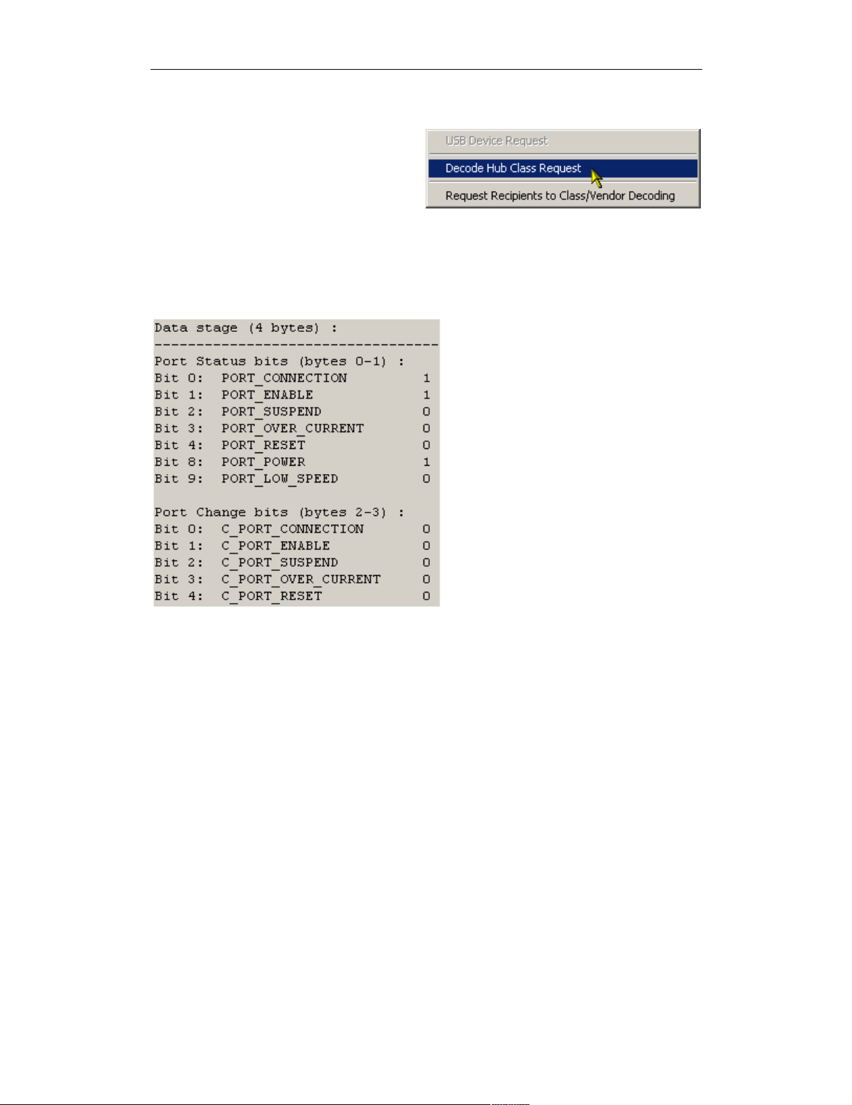
This example is taken from the hub.req GET_STATUS definition.
Bytes(2,3)={
Endian=Little
Name=Port Change bits
Bitmap={
0=C_PORT_CONNECTION
1=C_PORT_ENABLE
2=C_PORT_SUSPEND
3=C_PORT_OVER_CURRENT
4=C_PORT_RESET
}
}
In the trace output, the decoded
data can be viewed by positioning the mouse cursor over the
Data field name. This action
causes the Data field's tool tip
window to be displayed. The
box contains details about the
data, including the decoded
bitmap information.
Figure 7: Data field pop-up information box
11
Page 16
COMPUTER ACCESS TECHNOLOGY CORPORATION USB REQUEST DEFINITION (.REQ) FILES
Reference Manual
The information can also be viewed in
the decoding dialog window. Left-click
on the Control field heading to access
the Decode...Request command on the
context menu.
Selecting the Decode...Request
Figure 8: Decode...Request command on the
Control field pop-up menu
command opens the decoding dialog
window. The portion of the window that contains the decoded Bitmap data is shown
below.
Figure 9: Bitmap decoding in the decoding dialog
window
12
Page 17

COMPUTER ACCESS TECHNOLOGY CORPORATION USB REQUEST DEFINITION (.REQ) FILES
Reference Manual
Additional Request Keywords
The keywords Define, GroupName, GroupType, Standard, Class,
Vendor, ClassCode, VendorID, ProductID, AllRequests,
Request(...), wValue, wIndex, Data, WordValue, FormatValue,
and Bitmap have already been covered.
However, there are a number of additional keywords available to further define
requests. This section details the usage of those remaining keywords.
bmRequestType
Use bmRequestType to refer to the actual bmRequestType bitmap value. See
“Depends(...)” on page 15 for examples of its use.
Bytes(x, y)
Bytes(x, y) is used to identify a field within the Data stream. This field can be
subsequently decoded using one of the decoding keywords. The x and y values
represent the bytes to decode:
Data=
{
Bytes(0,1)=
{
FormatValue=The first two bytes are 0x%4X
}
}
A question mark (?) may be used to represent the y value. This will cause data
decoding to start at the byte specified by the x value, and continue all the way to the
last byte in the data. This example starts decoding at byte 5 and also decodes all data
that follows byte 5.
Bytes(5,?)
Color(R,G,B)
Use Color(R,G,B) to specify a color for the header portion of a Data field. The
color is represented inside the parentheses by its red, green and blue values. For
example,
Color(255, 0, 0)
will make a red header field.
Databytes(x, y)
Use Databytes(x, y) to identify a field in the Data stream on which a
Depends(...) definition for another Data field should be based.
13
Page 18

COMPUTER ACCESS TECHNOLOGY CORPORATION USB REQUEST DEFINITION (.REQ) FILES
Reference Manual
Its format is the same as for Bytes(x, y), except that “?” cannot be used. See
“Bytes(x, y)” on page 13 for formatting information.
Depends(Databytes(3,3))={
0x03={
Bytes(8,8)={
Name= Type of Ringback signalling is
WordValue={
0x00= Normal
0x01= busy
0x02= fast busy
0xff= Unknown Ring back type
}
FormatValue= Reserved for future use 0x%02X
}
}
0x04={
Bytes(8,8)={
Name= Type of connection:
WordValue={
...
}
FormatValue= Reserved for future use 0x%02X
}
}
0x05={
Bytes(8,8)={
Name= The Ringing Pattern present is
WordValue={
...
}
FormatValue= Reserved for future use 0x%02X
}
Bytes(9,9)={
Name= Size of the String (next n bytes)
FormatValue= Time of the incoming call as
delivered via Caller ID 0x%02X
}
}
}
14
Page 19

COMPUTER ACCESS TECHNOLOGY CORPORATION USB REQUEST DEFINITION (.REQ) FILES
Reference Manual
Depends(...)
Use Depends(...) to create a definition that displays a a field or a set of fields
in different ways, depending on certain conditions. It works similarly to a C
language switch statement. The basic structure of a Depends(...) definition
is this:
Depends(<keyword>[&<mask value>]
opt
)=
{
<value>=
{
...
}
...
[<keyword>= ...]
opt
}
Keywords
Keywords that can be used inside the parentheses of a Depends(...) definition
are: bmRequestType, Databytes(m,n), wIndex, and wValue. The value
to which the keyword refers is the condition that the decoding depends upon.
Possible values, along with their corresponding decoding definitions, are listed
within the curly braces on the right-hand side of the Depends(...) entry. In this
example,
wValue=
{
Depends(bmRequestType)=
{
0x01=
{
WordValue=
{
0x0000=One
}
}
0x02=
{
FormatValue=Two %d
}
}
}
15
Page 20

COMPUTER ACCESS TECHNOLOGY CORPORATION USB REQUEST DEFINITION (.REQ) FILES
Reference Manual
if the bmRequestType value is 0x01, the WordValue definition is used to
decode the request; on the other hand, if the value is 0x02, then the
FormatValue definition is used.
Default Branches
A default branch can be added to the Depends(...) definition:
wIndex=
{
Depends(bmRequestType)=
{
0x01=
{
FormatValue=Interface # %i status requested
}
FormatValue=Undefined bmRequestType, wIndex is
0x%02X
}
}
If the value of bmRequestType is 0x01, then the first FormatValue definition is applied. Otherwise, it defaults to the second FormatValue definition. The
default definition must be last in the list.
Mask Values
Use a bitwise & (AND) mask construct within Depends(...) to mask a value:
wValue=
{
Depends(wValue&0xFF00)=
{
0x0100=
{
WordValue=
{
0x01=One
}
}
0x0200=
{
FormatValue=Two %d
}
16
Page 21

COMPUTER ACCESS TECHNOLOGY CORPORATION USB REQUEST DEFINITION (.REQ) FILES
Reference Manual
FormatValue=Other (%0x02X)
}
}
This takes the current value of wValue, bitwise ANDs it with the 0xFF00 binary
value, and compares the result with the entries within the brackets in order to find
the branch it needs to follow.
HIBYTE and LOBYTE
HIBYTE and LOBYTE can be used with Depends(...) to mask wIndex and
wValue values. The Mask Value example could, alternatively, be written this way:
wValue=
{
Depends(HIBYTE(wValue))=
{
0x01=
{
WordValue=
{
0x01=One
}
}
0x02=
{
FormatValue=Two %d
}
FormatValue=Other (%0x02X)
}
}
Descriptors
Use Descriptors in a Data construct when the data in the data stage of this
request is a USB-defined descriptor or set of descriptors.
Data=
{
Length=?
Descriptors=TRUE
}
When the value of Descriptors is TRUE, the Data field will be labelled “De-
scriptors” and the descriptor information can be viewed by positioning the mouse
cursor over the Data field name. This action causes the Data field's tool tip window
to be displayed. The information can also be viewed in the decoding dialog window.
17
Page 22

COMPUTER ACCESS TECHNOLOGY CORPORATION USB REQUEST DEFINITION (.REQ) FILES
Reference Manual
Left-click on the Control field heading to access the Decode...Request command on
the context menu. Selecting the Decode...Request command opens the decoding
dialog window. For more information about displaying descriptor information,
please see USB Descriptor Definition (.dsc) Files on page 25.
Endian
Use Endian to specify whether bytes should be presented in little-endian or big-
endian order.
Bytes(2,3)={
Endian=Big
Name=Hub Change bits
Bitmap={
0=C_HUB_LOCAL_POWER
1=C_HUB_OVER_CURRENT
}
}
Alternatively, the Endian value could be set to Little, which is the default
value.
HIBYTE
Use HIBYTE in conjunction with LOBYTE in order to display both values in 2-byte
wValue and wIndex fields. HIBYTE refers to the Most Significant Byte. Here is an
example of its use:
wValue={
HIBYTE={
FormatValue=Cheese %d
}
LOBYTE={
FormatValue=, sliced %d
}
}
Here is sample output for the example when wValue equals 0x0102:
Figure 10: HIBYTE and
LOBYTE values displayed
Length
Use Length to represent the length, in bytes, of the data to be decoded. A numeric
value may be used:
18
Page 23
COMPUTER ACCESS TECHNOLOGY CORPORATION USB REQUEST DEFINITION (.REQ) FILES
Reference Manual
Length=1
Set Length to a numeric value when a certain specified amount of data should be
transferred during the data stage of a device request or as a structure on an endpoint.
Use a question mark (?) when an unknown number of bytes can be transferred:
Length=?
In this case, all of the data will be decoded.
LOBYTE
Use LOBYTE in conjunction with HIBYTE in order to display two values in 2-byte
wValue and wIndex fields. LOBYTE refers to the Least Significant Byte. Please see
“HIBYTE” on page 18 for examples.
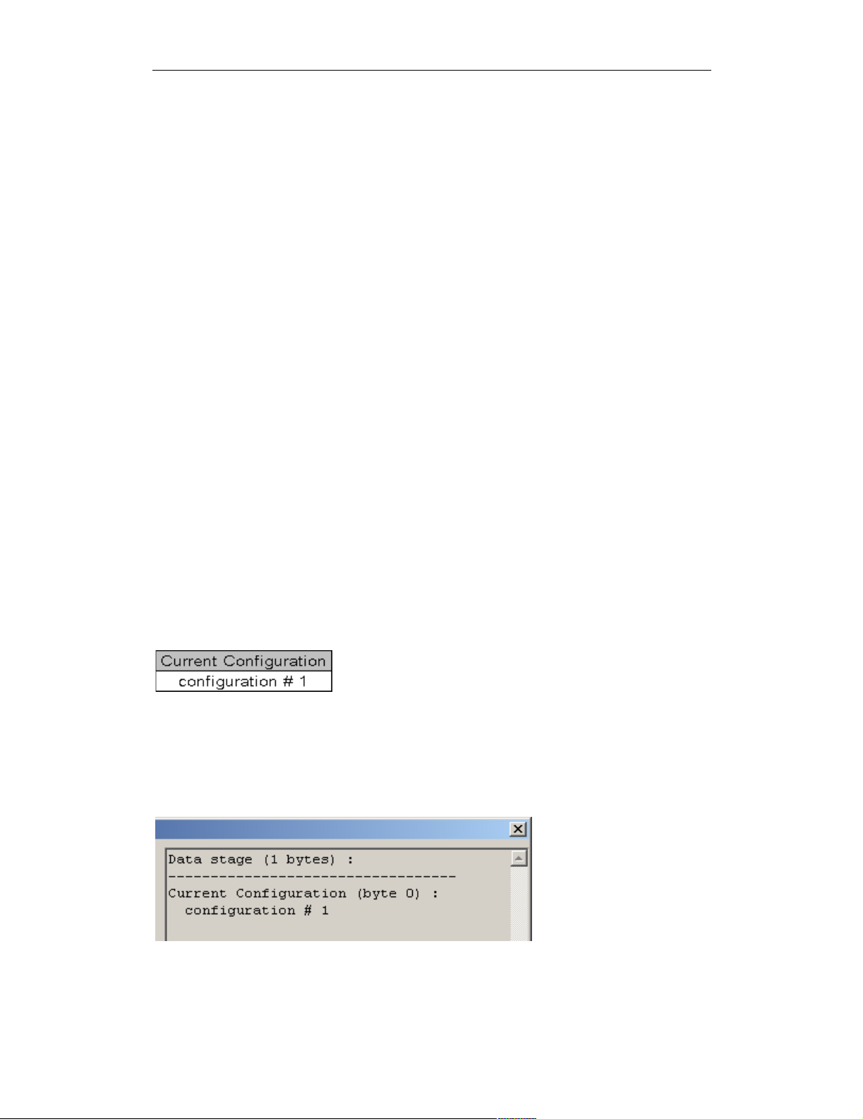
Name
Use Name to specify the header for a data field. The Name string will appear as the
title of the cell representing the data field, and the decoding for the field will appear
as the text for this cell. The Name string also serves as the title for the decoded bit
data in the Data field’s tooltip window in the case of bitmap decoding. For example,
this code from GET_CONFIGURATION in standard.req
Bytes(0,0)={
Name=Current Configuration
FormatValue= configuration # %d
}
could produce this cell:
Figure 11: NAME as title of data
field cell
Also, if the decoding dialog is launched, there will be two lines representing the
field – the first line will contain the Name string followed by a colon, and the second
will have the decoding of the field:
Figure 12: NAME string in decoding dialog
19
Page 24
COMPUTER ACCESS TECHNOLOGY CORPORATION USB REQUEST DEFINITION (.REQ) FILES
Reference Manual
See “Bitmap” on page 11 for another example of its use.
EndpointData Definitions
In addition to the AllRequests entry and the corresponding Request(...)
entries, a request definition file can have a set of EndpointData entries. An
EndpointData entry is used to define decoding for a class- or vendor-specific
data structure that can be transferred on USB using an Interrupt or Bulk endpoint,
according to a specific protocol. An example of this is the Hub and Port Change
Bitmap structure that can be transferred on the Interrupt endpoint (called Status
Change endpoint) according to Hub class protocol.
EndpointData entries contain Data definitions, which are preceded by some
global definitions for Caption, EndpointDirection, EndpointId,
EndpointType, MaxPacketSize and MaxTransferSize. The basic
structure of an EndpointData entry can be found on page 6.
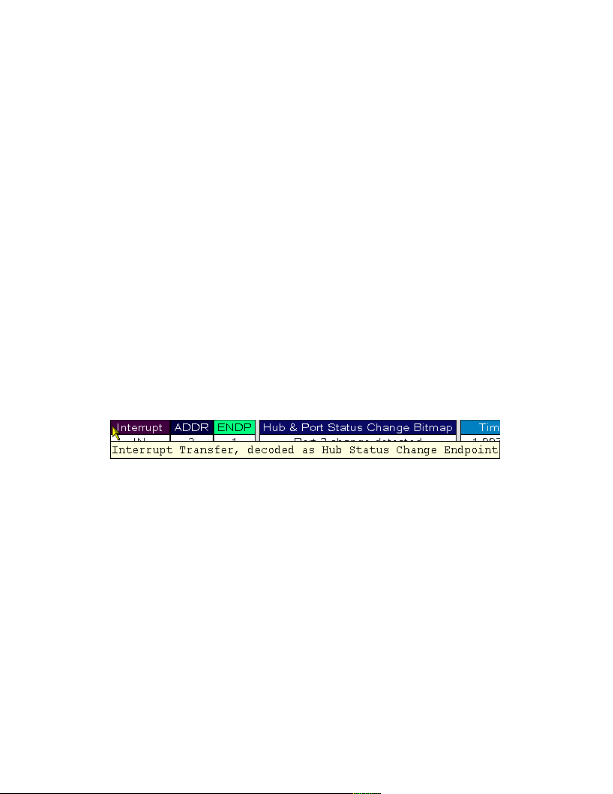
Caption
Use Caption to create an identifying string for the EndpointData decoding
definition. It will appear when the mouse is positioned over the endpoint type/
direction field. For example:
Caption=Hub Status Change Endpoint
Figure 13: Displayed Caption definition
20
Page 25
COMPUTER ACCESS TECHNOLOGY CORPORATION USB REQUEST DEFINITION (.REQ) FILES
Reference Manual
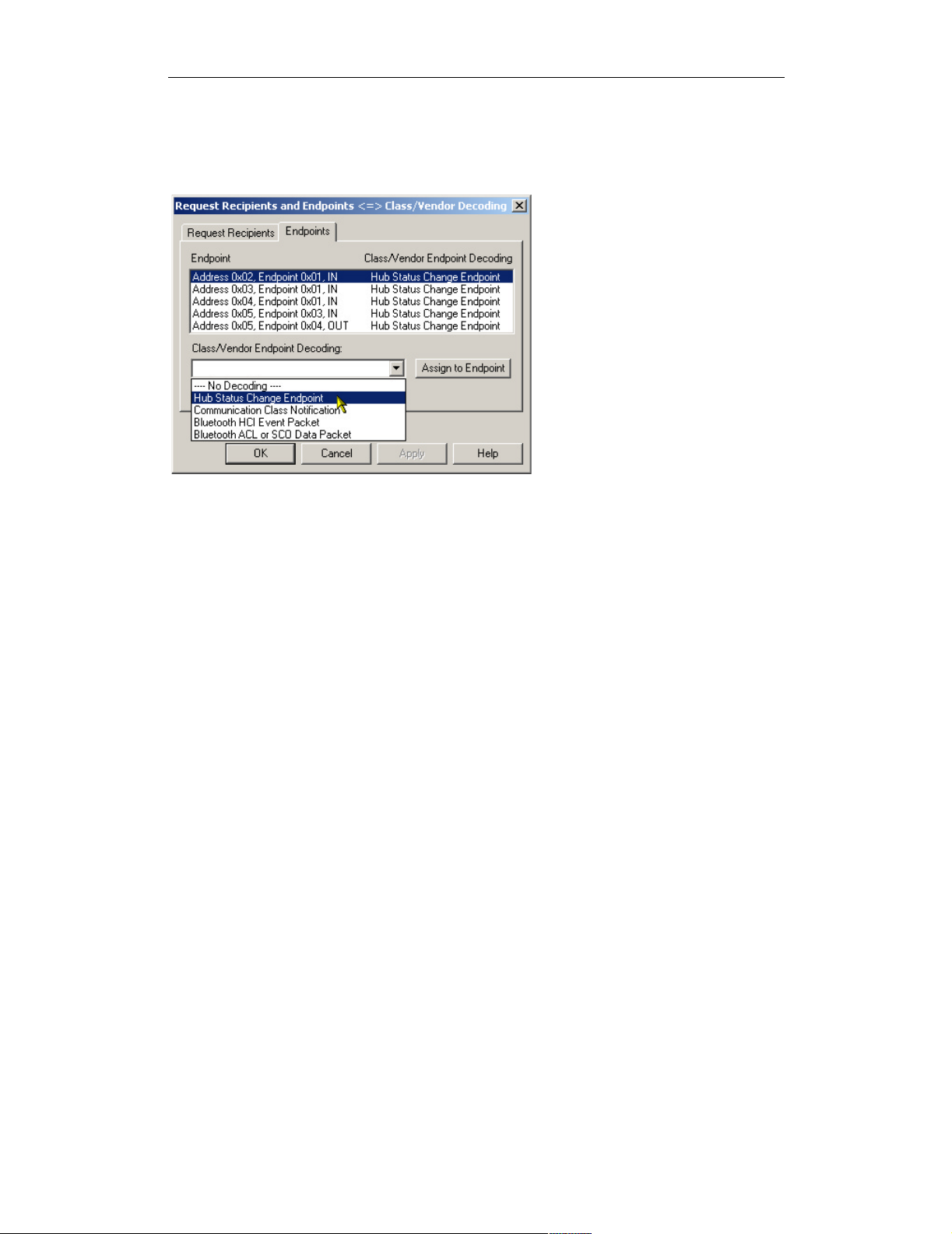
The Caption text will also show up in the Class/Vendor Endpoint Decoding drop-
down list on the Endpoints tab of the Request Recipients and Endpoints dialog box:
Figure 14: Caption text in the Class/Vendor Endpoint
Decoding drop-down list
EndpointDirection
Use EndpointDirection within an EndpointData entry to indicate the
direction of the data. It can be set to IN or OUT:
EndpointDirection=OUT
Please refer to EndpointData={...} in the hub.req sample file for a complete
example.
EndpointId
Use EndpointId if there is more than one Endpoint definition within the file,
each for data of different formats. EndpointId assigns an arbitrary number that
differentiates the definitions from one another. Please refer to
EndpointData={...} in the Bluetooth.req sample file for a complete
example.
EndpointType
Use EndpointType to identify the type of endpoint described in the definition.
EndpointType has two possible values in a .req file: Interrupt or Bulk.
Please refer to EndpointData={...} in hub.req sample file for a complete
example.
21
Page 26

COMPUTER ACCESS TECHNOLOGY CORPORATION USB REQUEST DEFINITION (.REQ) FILES
Reference Manual
MaxPacketSize
Use MaxPacketSize to assign the actual MaxPacketSize value for an endpoint.
Please refer to EndpointData={...} in the hub.req sample file for a complete
example.
MaxPacketSize=2
MaxTransferSize
Use MaxTransferSize to assign the actual MaxTransferSize value for an
endpoint. Please refer to EndpointData={...} in the hub.req sample file for a
complete example.
MaxTransferSize=2
Example
This example is taken from the Bluetooth.req sample file:
EndpointData={
; Global definitions
Caption=Bluetooth ACL or SCO Data Packet
EndpointType=Bulk
EndpointId=2
MaxPacketSize=64
MaxTransferSize=3573
;*** Field Definitions start here ********
Data={
Length=?
Bytes(0,1)={
Name=Connection Handle & Flags
FormatValue= 0x%04X
}
Bytes(2,3)={
Name=DataTotalLength
FormatValue= %d
}
Bytes(4,?)={
FormatValue=ACL or SCO Data
22
Page 27

COMPUTER ACCESS TECHNOLOGY CORPORATION USB REQUEST DEFINITION (.REQ) FILES
Reference Manual
}
}
}
Nested Request Definitions
Request entries may be nested when two or more requests with different
bRequest values require the same decoding for wIndex, wValue, and Data.
This eliminates the need to format the definitions separately for each request;
instead, they may be combined into one Request entry.
Nested Request definitions follow this format:
Request(<bRequest_first>)=
{
Request(<bRequest_second>)=
{
...
Request(<bRequest_last>)=
{
<definitions>
}
}
...
}
Here is an example of a nested Request entry:
Request (0)=
{
Request (1)=
{
wValue=
{
WordValue=
{
10=First value
20=Second value
}
FormatValue=Value is %d
}
}
}
For a more detailed, complex example, please refer to Audio.req.
23
Page 28

COMPUTER ACCESS TECHNOLOGY CORPORATION USB REQUEST DEFINITION (.REQ) FILES
Reference Manual
Comments
Comments can be inserted into both .req and .dsc files. There are no assigned
comment characters; text that doesn't follow the request file structure is simply
ignored. However, you may wish to designate a certain character, such as an asterisk
(*), to signal commented text. For example:
*Begin WordValue entry*
WordValue=
{
1=One
2=Two
} *End WordValue entry*
The text surrounded by the asterisks will be ignored.
24
Page 29

COMPUTER ACCESS TECHNOLOGY CORPORATION USB DESCRIPTOR DEFINITION (.DSC) FILES
Reference Manual
USB DESCRIPTOR DEFINITION
(.dsc) F
Descriptor definition (.dsc) files are used to configure decoding of class- or vendorspecific descriptors of any protocol. A .dsc file is a set of instructions that contains
definitions that describe, in USB-specific terms, how to take blocks of data and
break them into fields with consecutive decoding of each field. The descriptor definition files are text-based files that are identifiable by their .dsc extension. Customized decoding of USB descriptors is possible by editing or creating new definition
files.
The .dsc files work in conjunction with .req files in order to display descriptor in-
formation in a trace. A descriptor can be referred to by its DescriptorType
when a GET_DESCRIPTOR standard request (or any class- or vendor-specific Get
or SetDescriptor request, such as GET_HUB_DESCRIPTOR) is executed.
Also, when a CONFIGURATION descriptor is requested by the
GET_DESCRIPTOR standard request, a set of descriptors is supposed to be
returned by the USB device. This includes some standard descriptors (e.g.,
INTERFACE and ENDPOINT) and also can include class- and vendor-specific de-
scriptors. The .dsc definitions will work for both of those cases, using the
DescriptorType values and/or some other defined values, such as
DescriptorSubtype, ClassCode and Subclasscode.
ILES
This document describes the components of a .dsc file and the format for writing or
editing a .dsc file.
Please refer to the Universal Serial Bus Specification, version 1.1 for details about
USB protocol. The USB specification is available from the USB Implementers
Forum (USB-IF) at http://www.usb.org/.
Structure
Descriptor definition files are structured very similarly to request definition files;
however, a .dsc file can contain multiple descriptor definitions (inlcuding the
header, AllOffsets, and Offset structures), whereas a request file can contain
only one set of definitions.
Here is the basic structure for a .dsc file:
DescriptorName=<name>
DescriptorType=<wValue>
[DescriptorSubtype=< ? >]
[ClassCode=<class code>]
[SubclassCode=<subclass code>]
opt
opt
opt
25
Page 30

COMPUTER ACCESS TECHNOLOGY CORPORATION USB DESCRIPTOR DEFINITION (.DSC) FILES
Reference Manual
AllOffsets=
{
<Offset_value>=<Offset_name>
...
}
Offset(<Offset_value>)=
{
...
}
...
Entries
This section describes the basic entries that make up a .dsc file.
DescriptorName
The DescriptorName entry identifies the name for a descriptor definition. The
name is displayed in the Data field, as well as showing up at the top of the displayed
descriptor information.
DescriptorName=Example
Figure 15: DescriptorName display
DescriptorType
The DescriptorType entry is a numeric value that identifies a descriptor definition within in a .dsc file. It should match a wValue value in the corresponding
.req file’s GET_DESCRIPTOR definition. For example:
From standard.dsc:
DescriptorType=0x01
From standard.req (GET_DESCRIPTOR definition):
wValue={
...
HIBYTE={
26
Page 31

COMPUTER ACCESS TECHNOLOGY CORPORATION USB DESCRIPTOR DEFINITION (.DSC) FILES
Reference Manual
WordValue={
0x01=DEVICE type
0x02=CONFIGURATION type
0x04=INTERFACE type
0x05=ENDPOINT type
...
}
...
Data={
Length=?
Descriptors=TRUE
}
When wValue is 0x01, the decoder will look for a descriptor definition with a
DescriptorType value of 0x01. If found, the descriptor information will be
decoded and displayed in the trace output.
DescriptorSubtype
This entry is used only in conjunction with a DescriptorType entry. Its value
is the assigned subtype code. This keyword was introduced specifically to support
the descriptor format extension adopted by the Audio device class. Any other class
or vendor descriptor specification based on this extension may utilize the
DescriptorSubType keyword as well.
ClassCode
This entry is used only when the referring .req file contains GroupType=Class.
The ClassCode value is the USB-assigned class code. Its value should match the
ClassCode value in the .req file that references the descriptor definition.
Example from hub.req:
GroupName=Hub Class
GroupType=Class
ClassCode=0x09
Corresponding example from hub.dsc:
DescriptorName=HUB
DescriptorType=0x29
ClassCode=0x09
27
Page 32
COMPUTER ACCESS TECHNOLOGY CORPORATION USB DESCRIPTOR DEFINITION (.DSC) FILES
Reference Manual
SubclassCode
This entry is used only in conjunction with a ClassCode entry. Its value is the
USB-assigned subclass code. This keyword was introduced specifically to support
the descriptor format extension adopted by the Audio device class. Any other class
or vendor descriptor specification based on this extension may utilize the
SubclassCode keyword as well.
AllOffsets
The AllOffsets keyword is used to specify the Offset values for all of the
requests described in the descriptor definition. The AllOffsets definition uses
the following format:
AllOffsets=
{
<Offset_value>=<Offset_name>
...
}
The value of <Offset_value> is the USB-assigned value, and is represented
numerically. It shows up in the Offset column of the descriptor information box.
<Offset_name> is the textual representation of the offset value. It also repre-
sents the offset name that will appear in the Field column of the displayed descriptor
information. For example:
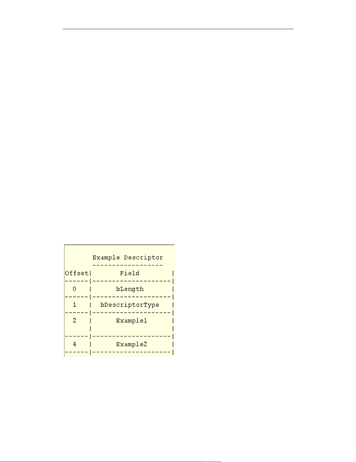
Figure 16: The offset value and name is
displayed in the Offset and Field columns of the
descriptor information
28
Page 33

COMPUTER ACCESS TECHNOLOGY CORPORATION USB DESCRIPTOR DEFINITION (.DSC) FILES
Reference Manual
AllOffsets=
{
2=Example1
4=Example2
}
Note: it's not necessary for the numeric Offset values to start from zero or to
increase sequentially. In addition, the numeric values may be in decimal or hexadecimal.
Offset(...)
Offset(...) defines an offset listed in the AllOffsets entry. Offset defini-
tions follow the format
Offset(<Offset_value>)=
{
...
}
The value of <Offset_value> should match the numeric value assigned to the
offset in the AllOffsets entry. For example:
Offset(2)=
{
...
}
Offset(4)=
{
...
}
Descriptor definitions
Just as the bulk of a request definition file is made up of Request(...) entries,
the main portion of a descriptor definition file is composed of Offset(...)
entries, which contain the actual descriptor definitions. They are structured very
similarly to Request(...) entries; therefore, only their differences will be
detailed here.
Decoding Definition Strings
Unlike request definitions, descriptor definitions do not us e t h e k eywords wValue,
wIndex and Data, since all of the descriptor information is data. Instead, the def-
initions are in the form of the contents of a Data entry.
29
Page 34
COMPUTER ACCESS TECHNOLOGY CORPORATION USB DESCRIPTOR DEFINITION (.DSC) FILES
Reference Manual
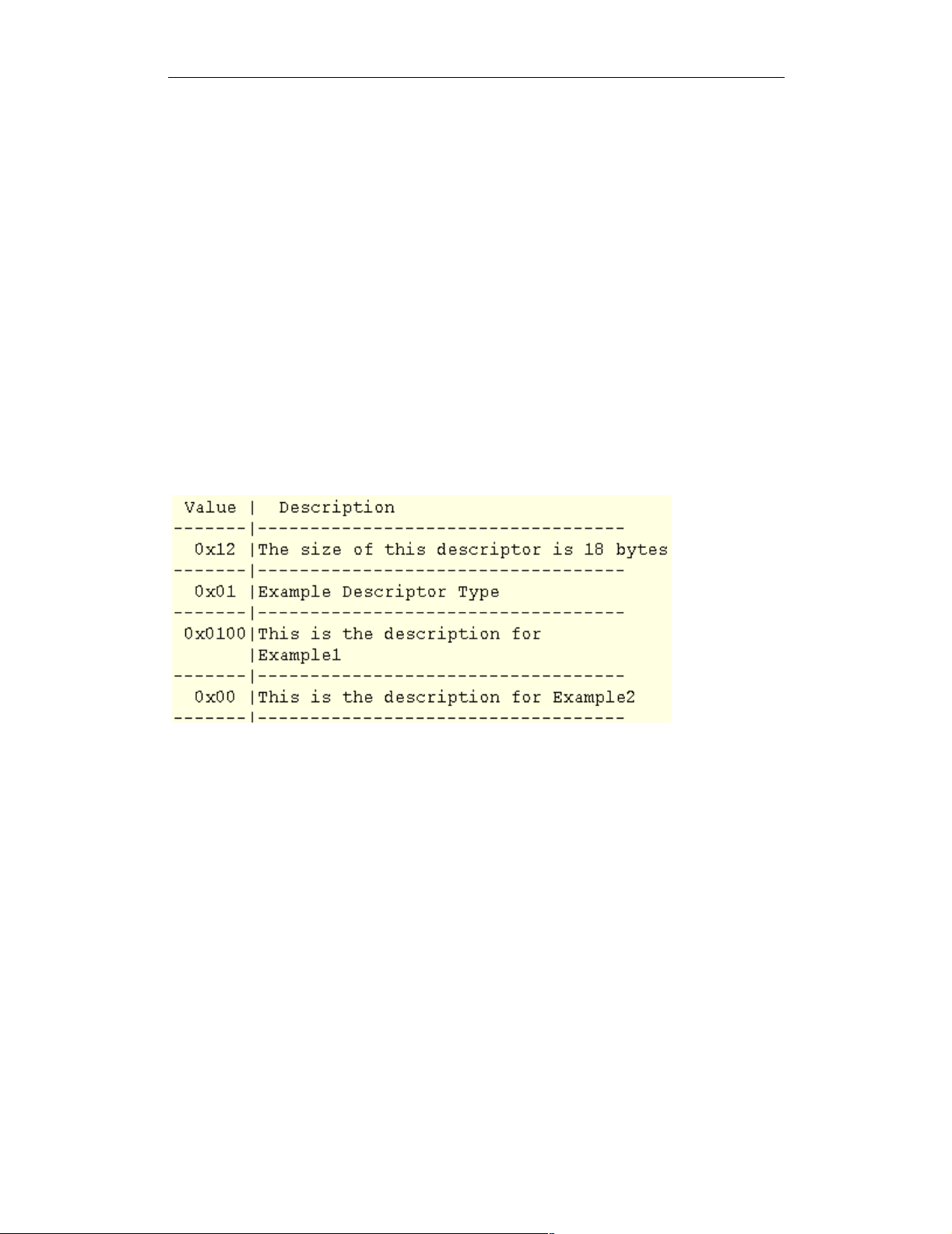
FormatValue, WordValue, and Bitmap
The structure of FormatValue, WordValue, and Bitmap entries is the same
as in a .req file. However, the output for all three is displayed in the Description
column of the descriptor information box. For example:
; Example1 description
Offset(2)={
FormatValue=This is the description for Example1
}
; Example2 description
Offset(4)={
WordValue={
0x00=This is the description for Example2
}
}
Figure 17: FormatValue, WordValue and Bitmap entries are displayed in
the Description column of the descriptor information box
Additional Descriptor Keywords
In addition to the keywords used in the basic structure of a .dsc file, there are a few
more keywords specific to these files. They are described in this section.
BCD
Use BCD to set up decoding of a Binary-Coded Decimal. The only value for BCD
is TRUE:
BCD=TRUE
Now, with BCD set to TRUE, two conversion specifications can be used in a
FormatValue entry, so that both the first byte and the second byte of the Binary-
Coded Decimal can be displayed:
30
Page 35
COMPUTER ACCESS TECHNOLOGY CORPORATION USB DESCRIPTOR DEFINITION (.DSC) FILES
Reference Manual
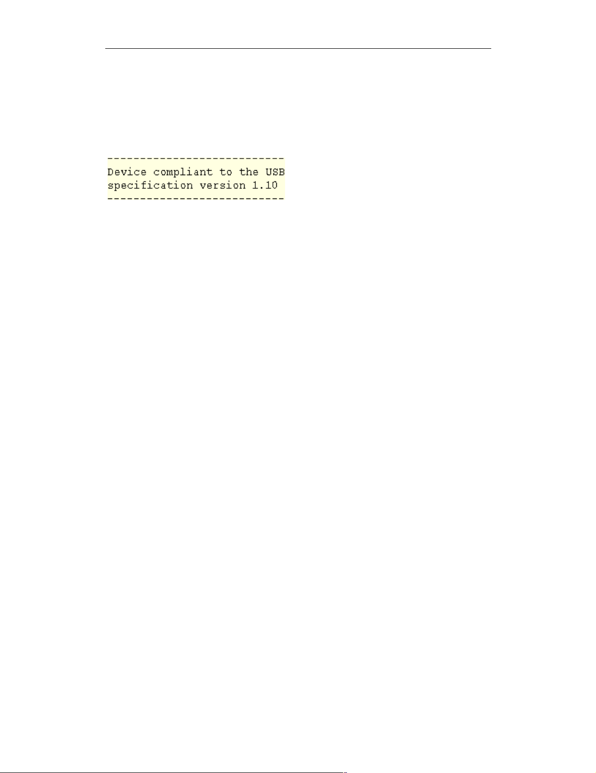
FormatValue=Device compliant to the USB specification
version %X.%02X
The output is displayed in the Description column of the descriptor information
box:
Figure 18: Possible output for BCD=TRUE
and conversion specification %X.%02X
Size
Use Size to indicate the number of bytes in the field. Example:
Size=2
Units
Use Units to take the Offset value and multiply it by the units value; the resulting
value can then be pulled into a FormatValue entry. The following example is
taken from the MaxPower description from the CONFIGURATION Descriptor
group in standard.dsc:
; MaxPower description
Offset(8)={
Units=2
FormatValue=Maximum power consumption of the device
in this configuration is %i mA
}
31
Page 36

COMPUTER ACCESS TECHNOLOGY CORPORATION USB DESCRIPTOR DEFINITION (.DSC) FILES
Reference Manual
32
 Loading...