

Page 1
Instruction Manual
USB2/USB2-HSIC
Decode and Trigger
Page 2

USB2/USB2-HSIC Decode and Trigger Instruction Manual
© 2014 Teledyne LeCroy, Inc. All rights reserved.
Unauthorized duplication of Teledyne LeCroy documentation materials other than for internal sales and
distribution purposes is strictly prohibited. However, clients are encouraged to distribute and duplicate
Teledyne LeCroy documentation for their own internal educational purposes.
Teledyne LeCroy is a trademark of Teledyne LeCroy, Inc. Other product or brand names are trademarks or
requested trademarks of their respective holders. Information in this publication supersedes all earlier
versions. Specifications are subject to change without notice.
922295 RevA
January 2014
Page 3

Instruction Manual
Contents
About This Manual 2
Assumptions 2
Compatibility 2
About the USB2 Options 3
Decode 3
Trigger 3
USB Decoding 4
Serial Decode Technical Overview 4
Decoding Workflow 5
Setting Up the Decoder 6
Working with the Decode Trace 9
Working with the Result Table 12
Applying Measurements with PROTObus MAG 14
USB Triggering 16
Serial Trigger Technical Overview 16
Linking Decoder to Trigger 16
USB2 Trigger Setup 17
Contact Teledyne LeCroy 21
922295 RevA
1
Page 4

USB2/USB2-HSIC Decode and Trigger
About This Manual
Teledyne LeCroy offers an array of toolsets for decoding and debugging serial data streams. These toolsets
may be purchased as optional software packages, or are provided standard with SDA and DDA model
oscilloscopes.
This manual explains how to use the following options.
l USB2.0 Decoder and Serial Trigger
l USB-HSIC Decoder
Assumptions
This manual is presented with the assumption that:
l You have a basic understanding of the serial data standard physical and protocol layer specifications,
and know how these standards are used in embedded controllers.
l You have a basic understanding of how to use an oscilloscope, and specifically the Teledyne LeCroy
oscilloscope on which the option is installed. Only features directly related to serial data decode and
trigger are explained in this manual; please see the oscilloscope online Help file, Operator's Manual or
Getting Started Manual for other instructions.
l You have purchased and installed one of the serial data decoders described in this manual.
Compatibility
Teledyne LeCroy is constantly expanding coverage of serial data standards and updating software. Some
capabilities covered in this documentation may only be available with the latest version of our firmware. You
can download the free firmware update from teledynelecroy.com.
While some of the screen images in this manual may not exactly match what is on your oscilloscope
display—or show an example taken from another standard—be assured that the functionality is nearly
identical, as much functionality is shared.
2
922295 RevA
Page 5

Instruction Manual
About the USB2 Options
USB 2.0 is a version of the Universal Serial Bus specification, which is used to connect a host controller
(typically a PC) to various devices. The 2.0 version brought a higher maximum bandwidth (480 Mb/s) and
features such as the Mini-B Connector, Battery Charging, and Micro-USB Cables and Connectors
specifications, to name a few.
High-Speed Inter-Chip (HSIC) technology communicates between microchips in an embedded sub-system
and leverages the traditional host-device topology of USB, utilizing a large amount of existing USB code. This
makes HSIC extremely lucrative in areas demanding fast time-to-market solutions, such as the mobile
industry including both smart phones and tablets.
USB standards are maintained by the non-profit USB Implementers Forum, Inc. (USB-IF). Additional
information, including specifications for specific versions, can be found on their website at www.usb.org/.
Decode
The USB2bus and USB2-HSIC decoder options apply software algorithms to extract packet-level data
consistent with the HSIC, USB 2.0, USB 1.1, and USB 1.0 standards from physical layer waveforms measured
on your oscilloscope. Token, Data, and Status information is displayed over the actual physical layer
waveforms, color-coded to provide fast, intuitive understanding of the relationship between USB packets and
other, time synchronous events.
Trigger
The USB2 TD (trigger and decode) option additionally allows triggering on predefined and user-defined
patterns in USB packets, errors, transactions, or bus events.
922295 RevA
3
Page 6

USB2/USB2-HSIC Decode and Trigger
USB Decoding
Serial Decode Technical Overview
The algorithms described here at a high level are used by all Teledyne LeCroy serial decoders sold for
oscilloscopes. They differ slightly for serial data signals that have a clock embedded in data or a clock
separate from data.
Bit-level Decoding
The first software algorithm examines the embedded clock for each message based on a default or userspecified vertical level. Once the clock signal is extracted or known, the algorithm examines the
corresponding data signal at the predetermined vertical level to determine whether a data bit is high or low.
The default vertical level is set to 50% and is determined from a measurement of peak amplitude of the
signals acquired by the oscilloscope. It can also be set to an absolute voltage level, if desired. The algorithm
intelligently applies a hysteresis to the rising and falling edge of the serial data signal to minimize the
chance of perturbations or ringing on the edge affecting the data bit decoding.
NOTE: Although the decoding algorithm is based on a clock extraction software algorithm using a vertical
level, the results returned are the same as those from a traditional protocol analyzer using sampling pointbased decode.
Logical Decoding
After determining individual data bit values, another algorithm performs a decoding of the serial data
message after separation of the underlying data bits into logical groups specific to the protocol (Header/ID,
Data Length Codes, Data, CRC, Start Bits, Stop Bits, etc.).
Message Decoding
Finally, another algorithm applies a color overlay with annotations to the decoded waveform to mark the
transitions in the signal. Decoded message data is displayed in tabular form below the grid. Various
compaction schemes are utilized to show the data during a long acquisition (many hundreds or thousands of
serial data messages) or a short acquisition (one serial data message acquisition). In the case of the
longest acquisition, only the most important information is highlighted, whereas in the case of the shortest
acquisition, all information is displayed with additional highlighting of the complete message frame.
User Interaction
The order of your interaction with the decoder software in many ways mirrors the order of the algorithms.
You will:
l Assign a protocol/encoding scheme, an input source, and a clock source (if necessary) to one of the
four decoder panels using the Serial Data and Decode Setup dialogs.
l Complete the remaining dialogs required by the protocol/encoding scheme to decode Transitions, Bits
and Words.
l Work with the decoded waveform, result table, and measurements to analyze the decode.
4
922295 RevA
Page 7

Instruction Manual
Decoding Workflow
While not required, we recommend the following workflow for decoding:
1. Set up the decoder.
2. Acquire a single burst of relevant data, then run the decoder.
NOTE:If the sampling rate (SR) is insufficient to resolve the signal adequately based on the bit rate (BR)
setup or clock frequency, the protocol decoding is turned OFF to protect you from incorrect data. The
minimum SR:BR ratio required is 4:1. It is suggested that you use a slightly higher SR:BR ratio if possible,
and use significantly higher SR:BR ratios if you want to also view perturbations or other anomalies on your
serial data analog signal.
3. Use the various analysis tools to verify that transitions are being correctly decoded. Tune the decoder settings as needed.
4. Run the decoder on acquisitions of the desired length.
You can disable/enable the decoder as desired without having to repeat the set up and tuning provided the
basic signal characteristics do not change.
922295 RevA
5
Page 8
USB2/USB2-HSIC Decode and Trigger
Setting Up the Decoder
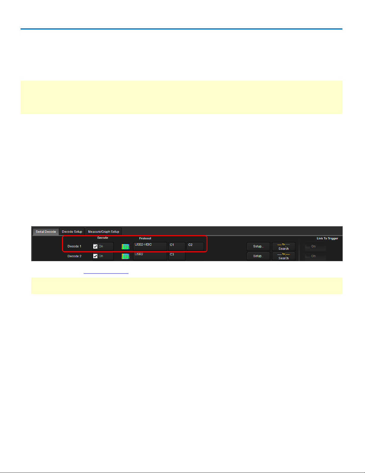
The main Serial Decode dialog allows you to preset up-to-four, independent decoders, Decode 1 to Decode
4. Each decoder can use different (or the same) protocols and data sources, or have other variations, giving
you maximum flexibility to compare different signals or view the same signal from multiple perspectives.
TIP: After completing setup for one decoder using the procedure below, you can quickly start setup for the
other decoders by using the Decode # buttons at the left of the Decode Setup dialog. You don't have to step
back to the Serial Decode dialog to start the setup. Controls with the same label on either dialog share the
same function.
1. Touch the Front Panel Serial Decode button (if available on your oscilloscope), or choose Analysis >
Serial Decode from the oscilloscope menu bar to access the Serial Decode dialog.
2. On the same row as the Decode # (shown below):
l Check On to enable the decoder now. This will let you view the decoding on screen as soon as
there is an acquisition, which helps to begin tuning. You can if you wish wait until all settings are
complete to enable the decoder.
l Select the desired Protocol to use. The selections will depend on the software options installed on
your instrument.
l Select the (Source) Data to be decoded. This can be any signal input channel (Cx), memory (Mx), or
math function (Fx).
l For HSIC decoders, enter the Strobe source channel under Clock.
3. Optionally, check Link To Trigger On to tie the decoder setup to an additional serial trigger setup.
NOTE: This checkbox will only appear if the oscilloscope is equipped with an activated a TD or TDM
package and any required serial trigger hardware.
4. Touch the Setup button (next to Search) to open the Decode Setup dialog. If you use this method rather
than the tab, your settings will be correctly pre-selected on the Decode Setup dialog.
5. Go on to complete the required USB2/USB2-HSIC settings on the right-hand dialogs next to the Decode
Setup dialog.
6
922295 RevA
Page 9

Instruction Manual
USB2 Decoder Settings
Probe Selection - select One Differential Probe, Two Single Ended Probes or One Single Ended Probe,
depending on your physical input setup.
If using Two Single Ended Probes, enter your Dp (Data positive) and Dn (Data negative) source channels
separately on the Decode Setup dialog to the left.
Bus Speed - select Low, Full, or High.
HSIC Decoder Settings
DataLevel - Enter the crossing level for the data waveform in Volts.
The DataLevel appears as a dotted horizontal line across the oscilloscope grid.
If initial decoding indicates that there are a number of error messages, make sure that the level is set to a
reasonable value.
StrobeLevel - Enter the crossing level for the strobe waveform in Volts.
Verifying Bit-Level Decode
When all Level or Basic dialog values are set (depending on protocol), you should already see a bit-level
decoding on the selected source trace. The Data Mode is set to bits by default, so that the remaining
protocol-specific settings do not matter for the initial bit-level decode.
In a correct bit-level decoding, bit transitions are all aligned with signal transitions, and the logical
interpretation of the bits is consistent with the physical level.
Review your decoded waveform for instances of incorrect bit-level decoding, particularly:
l Decoding at an exact multiple of the Bit Rate that would not allow further interpretation of the words
l Bits not aligned with the transitions
l Bit stream with gaps between the bits
922295 RevA
7
Page 10

USB2/USB2-HSIC Decode and Trigger
Enabling/Disabling the Decoder
Once preset, the four decoders can be enabled simultaneously or separately, although this number may be
limited depending on the type of source channels selected. Preset decoders can be easily disabled without
disrupting the configuration.
To enable:
Press the Front Panel Serial Decode button (if available on your oscilloscope), or choose Analysis > Serial
Decode, to open the Serial Decode dialog, then check Decode On next to the respective decoder.
If View Decode is checked (default) for that decoder on the Decode Setup dialog, a result table and decoded
waveform appear. The number of rows of data displayed on each table will depend on the Table#Rows
setting. The default is one, which can be increased, but doing so will decrease the amount of the screen
available to display traces.
To disable:
Deselect the Decode On box individually, or touch Turn All Off.
8
922295 RevA
Page 11

Instruction Manual
Working with the Decode Trace
Reading Waveform Annotations
When a decoder is enabled, an annotated waveform appears on the oscilloscope display, allowing you to
quickly read the results of the decode.
A colored overlay marks significant transitions in the source signal. The overlay contains annotations
corresponding to the data itself, any pre/post-message padding, inter-burst periods, etc. Each set of
annotations is customized to the protocol or encoding scheme.
The amount of information shown on an annotation is affected by the width of the rectangles in the overlay,
which is determined by the magnification (scale) of the trace and the length of the acquisition. Zooming a
portion of the decode trace will reveal the detailed annotations.
USB2 WAVEFORM ANNOTATIONS
These overlays appear on a USB2 waveform or its Zoom trace to highlight key elements of the decoded signal
(some annotations are not shown on the screen-shot).
Annotation Overlay Color
Transaction Dark Purple (behind all fields)
Packet (Handshake, Token, or Data) Charcoal (behind fields)
Control Sequences (Synch bits, PID
bits, Check bits, or EOP bits)
Device Address Light Purple
Endpoint Grey
Data Payload Green
CRC5 or CRC7 Royal Blue
Inter-packet Idle Royal Blue
Inter-transaction Idle Blue-Green
Green (different label over each field)
Decoded USB2 waveform. At this resolution, little information appears on the overlay.
922295 RevA
9
Page 12

USB2/USB2-HSIC Decode and Trigger
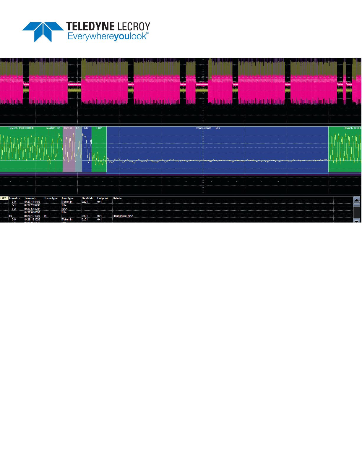
Zoom of transaction, showing annotation details.
HSIC WAVEFORM ANNOTATIONS
These overlays appear on an HSIC waveform or its Zoom trace to highlight key elements of the decoded
signal (some annotations are not shown on the screen-shot).
Annotation Overlay Color
Transaction Dark Purple (behind all fields)
Packet (Handshake, Token, or Data) Charcoal (behind fields)
Control Sequences (Synch bits, PID
bits, Check bits, EOP bits)
Device Address Light Purple
Endpoint Grey
Data Payload Green
CRC5 or CRC16 Royal Blue
Inter-packet Idle Royal Blue
Inter-transaction Idle Blue-Green
Green (different label over each field)
Initial decode of HSIC waveform.
10
Zoomed HSIC waveform showing annotations.
922295 RevA
Page 13

Instruction Manual
Searching Waveforms
Choosing Search on the Decode Setup dialog opens a Zoom of the original decoded waveform and displays the
corresponding Zoom dialog with the standard rescaling controls.
Enter the search criteria on the dialog:
SearchType - USB element to find. Options include Any, Event, Handshake Packet, Token Packet, Data Packet,
Transaction, or Protocol Error.
SearchSubtype - Type of the USB element selected in SearchType (e.g., can be ACK, NAK, or other supported
type when searching Handshake Packets).
Then, use the navigation buttons on the Search dialog to find the previous or next event in the trace that
matches the search criteria.
NOTE: If the match is found in a message currently displayed on the result table, that row will be highlighted.
However, if it is not displayed, the Search navigation buttons will not automatically bring up that row on the
table, although they will navigate the trace. Use the scrollbar at the right of the result table to find the
highlighted row containing the search result.
The default Zoom always presents the found event at the full width of the grid. Use the Zoom dialog controls
to rescale the Zoom to the desired level of magnification.
922295 RevA
11
Page 14

USB2/USB2-HSIC Decode and Trigger
Working with the Result Table
By default, a table summarizing the decoder results appears below the grids whenever a decoder is enabled.
The result table provides a view of message data as decoded during the most recent acquisition, even when
messages are too compact to allow annotation on the waveform trace.
The table is displayed only when the View Decode checkbox is marked on the Decode Setup Dialog and a
source signal has been decoded using that protocol.
You can customize the result table, changing both the number of rows and the columns displayed.
The default is one row. On a single-row table, touch the Down arrow at the far right to open a
scrollbar that let's you display the previous or next row to data.
You can also export result table data to a .CSV file, and the table itself is useful for navigating and
measuring.
This extracted USB2 and USB2-HSIC data appears on the decoder result table.
Column Extracted or Computed Data
Idx (always shown) Number of the line in the result table.
TransIdx Number of the transaction in the signal, labeled Tx. Packets and idles belonging
to this transaction are all prefixed with this number.
Time(µ) Time in microseconds elapsed from start of acquisition to start of transaction
TransType Transaction type
ItemType Packet type
DevAddr Device Address
Endpoint Endpoint
Details Extracted values
Section of typical USB2-HSIC result table.
12
922295 RevA
Page 15

Instruction Manual
Customizing the Result Table
Follow these steps to change what data appears in the result table:
1. Press the Front Panel Serial Decode button, or choose Analysis > Serial Decode, then open the Decode
Setup tab.
2. Touch the Configure Table button.
3. On the View Columns pop-up dialog, check boxes for the columns you want to appear in the table. Clear
boxes for any columns you wish to remove. Only those columns selected will appear on the oscilloscope
display.
To return to the preset display, touch Default.
4. Optionally, set a BitRate Tolerance percentage. This will help correct signal jitter while decoding.
5. Touch the Close button when finished.
6. Optionally, on the Decode Setup dialog enter the Table # Rows to display.
NOTE: Keep in mind that displaying several, multiple-row tables will reduce the amount of screen space
available for the waveform grids.
Navigating with the Result Table
Besides displaying the decoded serial data, the result table enables you to quickly Zoom regions of the
decoded waveform and control decoder dialogs.
The first column heading (top, left-most cell of the table header) bears the name of the corresponding
protocol, and the cell's fill color matches the color of the input source. Touching this cell opens the Decode
Setup dialog if it has been closed.
Touching the row number in the first column opens a Zoom of the corresponding region in the decode trace.
Touching any other data cell in the table opens a pop-up menu with several choices of action:
l Off turns off the decoder .
l Zoom creates a zoom of the region where the data appears (same as touching the row number).
l Setup opens the Decoder Setup dialog (same as touching the first column heading).
l Export exports the decode results table to a .CSV file.
l Measure displays a choice of PROTObus MAG measurements that can be made on the source signal.
Exporting Result Table Data
You can export the decoder result table data to a .CSV file.
Export files are by default created in the Xstream\Applications\<protocol> folder, although you can choose any
other folder on the oscilloscope or any external drive connected to a host USB port. The data will overwrite the
last export file saved in the protocol directory, unless you enter a new filename.
To export the result table:
1. Press the Front Panel Serial Decode button, or choose Analysis > Serial Decode, then open the Decode
Setup tab.
2. Optionally, touch Browse and enter a new File Name and output folder.
3. Touch the Export Table button.
922295 RevA
13
Page 16

USB2/USB2-HSIC Decode and Trigger
Applying Measurements with PROTObus MAG
If you have purchased and installed the PROTObus MAG option with your decoder, special measurements
designed for debugging serial data streams can be applied to the decoded waveform. These measurements
appear in a tabular readout below the grid (the same as for any other measurements) and are in addition to
the result table that shows the decoded data. You can set up as many measurements as your oscilloscope
has parameter locations.
Applying Measurements from the Result Table
PROTObus MAG offers a sub-set of measurements designed for serial data analysis. To quickly apply these
measurements:
1. Touch any data cell of the decode result table.
NOTE:If you're running more than one decoder simultaneously, be sure to select a cell from the correct
table, as the measurement source will be whichever waveform belongs to the table you touch.
2. From the pop-up menu, select Measure to display the Select Operation... dialog.
3. Touch any measurement operation to select it. Options are:
l View Serial Encoded Data as Analog Waveform - Automatically sets up a Message to Value param-
eter and then tracks the assigned measurement. In doing so, a Digital-to-Analog Conversion (DAC)
of the embedded digital data is performed and the digital data is displayed as an analog waveform.
l Message to Value - Extract and convert a specific portion of the data/payload in the message and
display it as an analog value.
l MsgToAnalog (Message to Analog) - Computes the time difference from a protocol message to the
crossing of a threshold on an analog signal.
l AnalogToMsg (Analog to Message) - Computes the time difference from the crossing of a thresh-
old on an analog signal to a protocol message.
14
922295 RevA
Page 17

Instruction Manual
l MsgToMsg (Message to Message) - Computes the time difference from one protocol message to
another protocol message.
l DeltaMsg (Delta Message) - Computes the time difference between two messages on a single
decoded line.
l Time@Msg (Time at Message) - Time from trigger to each protocol message (meeting specified
conditions).
l BusLoad - Computes the load of user-defined messages on the bus (as a percent).
l MsgBitrate - Computes the bitrate of user-specified messages on decoded traces.
l NumMessages (Number of Messages) - Computes the number of messages which match a user-
specified definition in decoded traces.
4. On the next dialog, choose a parameter location (P1-Px) in which to run the measurement.
NOTE: If you choose a location that already stores a measurement, this selection will overwrite that setup.
Applying Measurements from the Decode Setup Dialog
You can also access PROTObus MAG serial data measurements by touching the Measure button on the
Decode Setup dialog. Follow Steps 3 and 4 above to set up the measurements. Measurements are set on the
source of whichever Decoder (1-4) is currently selected on the Decode Setup dialog.
Applying Measurements from the Measure Menu
The full menu of available measurements can be accessed through the menu bar. Standard measurements
are available even if you do not have the PROTObus MAG option installed.
Choose Measure > Measure Setup and follow the usual procedures for setting up a measurement. In this case,
you will have to manually choose the source waveform to measure, as the Decoder output is not pre-selected.
922295 RevA
15
Page 18

USB2/USB2-HSIC Decode and Trigger
USB Triggering
Serial Trigger Technical Overview
TD options provide advanced serial data triggering. Serial data triggering is implemented directly within the
hardware of the oscilloscope acquisition system and utilizes the decoder algorithms to recognize userdefined serial data patterns. This allows a recognized pattern to be used to trigger the oscilloscope, while
other signals coincident with the desired pattern can be simultaneously captured.
Linking Decoder to Trigger
A quick way to set up a serial trigger is to link it to a decoder by checking the Link to Trigger On box on the
Serial Decode dialog.
Linking decoder to trigger allows you to configure trigger parameters with the exact same values that are
used for decodiing the signal, saving the extra effort needed to re-enter parameter values used to decode the
signal on the serial trigger set up dialogs.
<Also, why do you pick channels or Ext for the data source on the trigger setup dialog when presumably it is
the decoder that recognizes the serial data pattern? why would you ever want to use anything but Decode1-4
as the source? >
16
922295 RevA
Page 19

Instruction Manual
USB2 Trigger Setup
USB2 triggers fall into four basic types of Packet, Protocol Error, Transaction, and Bus Event. The setups for
each type of trigger differ significantly and so are described in separate procedures below. Only the first group
of settings describing the source Setup is utilized by all the trigger types.
To begin, access the Serial Trigger dialog:
l Touch the Trigger descriptor box, or choose Trigger > Trigger Setup from the Menu Bar.
l Touch the Serial Type button, and the USB2 Standard button.
Setup
Bus Speed - Select the signaling rate of the trigger source, then make any other entries required by your
selection:
l Low and Full - Enter the D+ (Data positive) and D- (Data negative) source channels and waveform cross-
ing levels. These may be the same or different channels depending on whether your trigger setup utilizes a differential probe or two single-ended probes.
l High - High speed USB triggering is only available on Channel 4, which is preselected for you when you
choose High. Be sure your input is connected to this channel.
Error Trigger
This will trigger upon encountering the first error of the type(s) you have selected.
1. Choose Pattern Type Protocol Error.
2. Select as many of the error types as you wish.
Bus Event Trigger
This will trigger upon encountering the first of the selected type(s) of bus events. Options vary depending on
the bus speed.
1. Choose Pattern Type Bus Event.
2. Select as many of the event types as you wish.
922295 RevA
17
Page 20

USB2/USB2-HSIC Decode and Trigger
Transaction Trigger
This will trigger upon finding transactions that meet all the Token, Data, and Handshake packet criteria.
Options vary depending on the bus speed. The principal difference between a Transaction trigger and a
Packet trigger is that for a Transaction trigger, the specified packet types simply need to be found in the
transaction, whereas for a Packet trigger, the packet types and values must meet the criteria.
1. Choose Pattern Type Transaction.
2. Choose to enter values in Binary or Hexadecimal (Hex) format. The selection propagates throughout the
entire trigger setup. Toggling between formats does not result in loss of information, but will transform
the appearance of values.
3. Select the Token Type:
l Any Type triggers on any Token packet that meets the remaining criteria.
l In, Out, Setup, and Ping (High Speed only) trigger only when one of these Token types meet the remain-
ing criteria.
3. Enter the Token DevAddress (Device Address) and Endpoint values.
4. To add a Data criteria to the trigger, choose the Data Type, otherwise leave Any Type selected. Not Exist
will trigger when there is no Data packet in the transaction.
5. To add a Handshake criteria to the trigger, choose the Handshake Type, otherwise leave Any Type
selected. Not Exist will trigger when there is no Handshake packet in the transaction.
Packet Trigger
This type of trigger can be set on complex patterns in any packet field—token, data, or handshake—or on a 116 byte user-defined data pattern. Different controls for specifying the pattern will be activated depending on
the Category selection.
TRIGGER ON ANY USB2 PACKET
Choose Pattern Type Packet and Category Any Sync.
18
922295 RevA
Page 21

Instruction Manual
TRIGGER ON TOKEN PATTERN
1. Choose Pattern Type Packet and Category Token.
2. Choose to enter values in Binary or Hexadecimal (Hex) format. The selection propagates throughout the
entire trigger setup. Toggling between formats does not result in loss of information, but will transform the
appearance of values.
3. Use the three Token # PID controls to define the firt, second, and third token patterns that will fire the
trigger.
NOTE: Options will vary by bus speed. Additional controls will appear below some selections; enter these,
as well. If you only want to define one or two patterns, choose Disable in Token 2 or 3.
l Any (Token 1 PID) triggers upon finding any token packet . If Any is selected, the remaining Token # PID
controls are disabled, as the first token encountered will fire the trigger.
l In, Out, Setup, and Ping trigger when a token of the that type contains the values entered in DevAddress
and EndPoint.
l Split (HighSpeed only) triggers when a split contains the values entered in Hub Address, SC, Port
number and S, E, or ET.
l SOF (Full and High Speed only) triggers when Start of Frame value matches the Frame Number entered.
l Preamble (Full Speed only) triggers when the token contains a preamble.
TRIGGER ON DATA PATTERN
1. Choose Pattern Type Packet and Category Data.
2. Choose to enter values in Binary or Hexadecimal (Hex) format. The selection propagates throughout the
entire trigger setup. Toggling between formats does not result in loss of information, but will transform the
appearance of values.
3. Use the three Data Pattern # PID controls to define up-to-three data patterns that will fire the trigger.
NOTE: Options will vary by bus speed. Additional controls will appear below each selection; enter these, as
well. If you only want to define one or two patterns, choose Disable in Data Pattern 2 or 3.
l Any Type triggers upon finding any data packet that satisfies the remaining criteria.
l Data0, Data1, Data2, and MData will trigger only when that type of data packet matches the criteria.
922295 RevA
19
Page 22

USB2/USB2-HSIC Decode and Trigger
4. In Compare Type, choose to compare Data Values or Data Lengths to find a match.
5. If you chose to compare lengths, enter the Cmp. Opr. (operator) and Length (in bytes) that define the
trigger criteria (e.g., Trigger if Data0 length is greater than 4 bytes).
If you chose to compare values, enter the Cmp. Opr. (operator), At position, and a reference Data (1-16
Bytes) pattern that define the trigger criteria (e.g., Trigger if the value at position x in Data0 is equal to y).
TRIGGER ON HANDSHAKE PATTERN
1. Choose Pattern Type Packet and Category Handshake.
2. Select the handshake type that will fire the trigger: Any Type, ACK, NAK, STALL, NYET (High Speed only),
or Error) (High Speed only).
TRIGGER ON USER-DEFINED PATTERN
1. Choose Pattern Type Packet and Category User Define.
2. Choose to enter values in Binary or Hexadecimal (Hex) format. The selection propagates throughout the
entire trigger setup. Toggling between formats does not result in loss of information, but will transform
the appearance of values.
3. In Data (1-16 Bytes), enter the pattern that will fire the trigger.
20
922295 RevA
Page 23

USB2/USB2-HSIC Decode and Trigger
Contact Teledyne LeCroy
United States and Canada
- World Wide Corporate Office
Teledyne LeCroy Corporation
700 Chestnut Ridge Road
Chestnut Ridge, NY, 10977-6499, USA
Ph: 800-553-2769 / 845-425-2000
FAX: 845-578-5985
teledynelecroy.com
Support:
contact.corp@teledynelecroy.com
Sales:
customersupport@teledynelecroy.com
United States Protocol Solutions Group
Teledyne LeCroy Corporation
3385 Scott Boulevard
Santa Clara, CA, 95054, USA
FAX: 408-727-0800
teledynelecroy.com
Sales and Service:
Ph: 800-909-7211 / 408-727-6600
contact.corp@teledynelecroy.com
Support:
Ph: 800-909-7112 / 408-653-1260
psgsupport@teledynelecroy.com
European Headquarters
Teledyne LeCroy SA
4, Rue Moïse Marcinhes
Case postale 341
1217 Meyrin 1
Geneva, Switzerland
Ph: + 41 22 719 2228 / 2323 / 2277
FAX: +41 22 719 2233
contact.sa@teledynelecroy.com
applications.indirect@teledynelecroy.com
teledynelecroy.com/europe
Protocol Analyzers:
Ph: +44 12 765 03971
Singapore, Oscilloscopes
Teledyne LeCroy Singapore Pte Ltd.
Blk 750C Chai Chee Road #02-08
Technopark @ Chai Chee
Singapore 469003
Ph: ++ 65 64424880
FAX: ++ 65 64427811
Singapore, Protocol Analyzers
Genetron Singapore Pte Ltd.
37 Kallang Pudding Road, #08-08
Tong Lee Building Block B
Singapore 349315
Ph: ++ 65 9760-4682
China
Teledyne LeCroy Corporation Beijing
Rm. 2001
Unit A, Horizon Plaza
No. 6, Zhichun Road, Haidian District
Beijing 100088, China
Ph: ++86 10 8280 0318 / 0319 / 0320
FAX:++86 10 8280 0316
Service:
Rm. 2002
Ph: ++86 10 8280 0245
Taiwan
LeColn Technology Co Ltd.
Far East Century Park, C3, 9F
No. 2, Chien-8th Road,
Chung-Ho Dist., New Taipei City, Taiwan
Ph: ++ 886 2 8226 1366
FAX: ++ 886 2 8226 1368
Korea
Teledyne LeCroy Korea
10th fl.Ildong Bldg.
968-5 Daechi-dong, Gangnam-gu
Seoul 135-280, Korea
Ph: ++ 82 2 3452 0400
FAX: ++ 82 2 3452 0490
Japan
Teledyne LeCroy Japan
Hobunsya Funchu Bldg, 3F
3-11-5, Midori-cho, Fuchu-Shi
Tokyo 183-0006, Japan
Ph: ++ 81 4 2402 9400
FAX: ++ 81 4 2402 9586
teledynelecroy.com/japan
922295 RevA
21
Page 24

 Loading...