

Teledyne ULTRAFLOW 150 Operation Manual

ULTRAFLOW 150
GAS FLOW AND TEMPERATURE MONITOR
OPERATIONS MANUAL
SERIAL NUMBER: _________________________

DOCUMENT NO.: 1900-0100-01 REV. E

JANUARY 2014
Proprietary Information. All rights reserved by Teledyne Monitor Labs. No part of this
book may be reproduced or copied in any form or by any meansgraphic, electronic, or
mechanical, including photocopying, taping, or information storage and retrieval
systemswithout written permission of the publisher.
Made in the United States of America

TABLE OF CONTENTS
PAGE
1.0 SAFETY ....................................................................................................................................... 1-1
1.1 Internationally Recognized Symbols Used on Teledyne Monitor Labs Equipment ..................... 1-1
2.0 SYSTEM OVERVIEW ................................................................................................................. 2-1
2.1 System Description, Standard Equipment ................................................................................... 2-1
2.1.1 Transducer Interface Enclosure (TIE) ........................................................................... 2-1
2.1.2 Purge Nozzle Assemblies ............................................................................................. 2-1
2.1.3 Protective Purge System ............................................................................................... 2-3
2.1.4 Enhanced Remote Panel .............................................................................................. 2-3
2.2 Specifications (Standard System) ............................................................................................... 2-5
3.0 OPTIONAL EQUIPMENT ............................................................................................................ 3-1
3.1 Protective Purge Air System, (Dual) ............................................................................................ 3-1
3.2 Local User Interface Key Pad and Display .................................................................................. 3-1
3.3 Dual Analog Input Board ............................................................................................................. 3-2
3.3.1 Barometric Pressure Sensor Assembly ........................................................................ 3-2
3.3.2 External Temperature Measurement ............................................................................ 3-3
3.4 Link Rod ....................................................................................................................................... 3-4
3.5 6PT I/O PC Board option for 150DI ............................................................................................. 3-5
4.0 THEORY OF OPERATION ......................................................................................................... 4-1
4.1 Physics of Measurement ............................................................................................................. 4-1
4.1.1 Time of Flight Theory .................................................................................................... 4-1
4.1.2 Flow Volume Measurement .......................................................................................... 4-3
4.1.3 Wet Basis and Dry Basis Measurements ...................................................................... 4-3
4.1.4 Correction to Standard Temperature and Pr essure ...................................................... 4-3
4.2 Monitor Specific Theory ............................................................................................................... 4-4
4.2.1 Box Car Integration ....................................................................................................... 4-4
4.2.2 Operational Modes of the Transducer Interfac e E nclosure .......................................... 4-4
5.0 TRANSDUCER INTERFACE ENCLOSURE (TIE) ...................................................................... 5-1
5.1 Mechanical Description ............................................................................................................... 5-1
5.2 Electrical Description ................................................................................................................... 5-2
5.2.1 External Interface PC Board ......................................................................................... 5-2
5.2.2 Power Supply Board ..................................................................................................... 5-2
5.2.3 Flow Mother Board ........................................................................................................ 5-2
5.2.4 Preamp Boards ............................................................................................................. 5-8
5.2.5 (Optional) Dual Analog Input Board .............................................................................. 5-9
5.2.6 (Optional) Local User Interface Key Pad and Display Assembly .................................. 5-9
5.2.7 Individual Button Function (When Pres sed by Themselves) ...................................... 5-12
5.2.8 Combinations of Buttons ............................................................................................. 5-13
5.2.9 6PT I/O PC Board option for 150DI ............................................................................ 5-13
6.0 ENHANCED REMOTE PANEL W / MULTI I/O MODULE .......................................................... 6-1
6.1 Overview ..................................................................................................................................... 6-1
6.2 Mechanical Description ............................................................................................................... 6-1
6.3 Electrical Description ................................................................................................................... 6-2
6.3.1 Input Power Requirement ............................................................................................. 6-2
6.3.2 Circuit Description (Overview)....................................................................................... 6-2
6.4 Operational Description--Menu Structure and U ser Interface ..................................................... 6-9
6.4.1 Memory Test ................................................................................................................. 6-9

TABLE OF CONTENTS
(Continued)
PAGE
6.4.2 Main Display Screen ................................................................................................... 6-10
6.4.3 Main Menu Screen ...................................................................................................... 6-11
6.4.4 Service Data Menu ...................................................................................................... 6-12
6.4.5 Status Code Help ........................................................................................................ 6-12
6.4.6 Output Cal Tests ......................................................................................................... 6-13
6.4.7 Output Module Configuration Menu ............................................................................ 6-16
6.4.8 Display Properties Menu ............................................................................................. 6-18
6.4.9 Software Versions ....................................................................................................... 6-19
6.4.10 System Properties Menu ........................................................................................... 6-19
6.4.11 View Trending Data ................................................................................................... 6-22
6.4.12 View Numerical Data ................................................................................................. 6-23
6.4.13 View Status History ................................................................................................... 6-23
6.4.14 View Alarms History .................................................................................................. 6-23
6.5 Multi I/O Software ...................................................................................................................... 6-24
6.5.1 Analog Outputs ........................................................................................................... 6-24
6.5.2 Digital Inputs ............................................................................................................... 6-24
6.5.3 Digital Outputs ............................................................................................................. 6-25
7.0 INSTALLATION ........................................................................................................................... 7-1
7.1 Pre-Installation Planning and Preparation ................................................................................... 7-1
7.2 Site Selection ............................................................................................................................... 7-1
7.2.1 Representative Sampling Location ............................................................................... 7-2
7.2.2 Access to Sampling Location ........................................................................................ 7-2
7.2.3 Environmental Conditions at the Sampling L ocation .................................................... 7-2
7.3 Equipment Mounting Considerations .......................................................................................... 7-2
7.3.1 Flange and Mounting Tube Installation ......................................................................... 7-2
7.3.2 Purge System, Reference PURGE ASS’Y MTG., PLUMBING & CLEARANCE
REQUIREMENTS Drawing ...................................................................................... 7-3
7.3.3 Purge Nozzle and Mounting Flange Assembly , Reference PURGE NOZZLE AND
MTG. PLATE INSTALLATION-150 Drawing ............................................................ 7-4
7.3.4 Transducer Interface Enclosure Assembly, Reference XDUCER INTERFACE
ENCLOSURE INSTALLATION Drawing .................................................................. 7-5
7.3.5 Junction Box, Reference JUNCTION BOX MTG. METHODS AND
CLEARANCES Drawing ........................................................................................... 7-5
7.3.6 Enhanced Remote Panel Assembly, Reference ENHANCED REMOTE PANEL
ASSEMBLY Drawing ................................................................................................ 7-5
8.0 SYSTEM CALIBRATION AND ADJUSTMENT ........................................................................... 8-1
8.1 Transducer Interface Enclosure Calibrati on ................................................................................ 8-1
8.1.1 Transducer Interface Enclosure Progra m V ariables ..................................................... 8-1
8.2 Transducer Interface Enclosure Elec tronics Adjustment ............................................................ 8-8
8.2.1 Flow Mother Board ........................................................................................................ 8-8
8.2.2 Preamp Board Adjustment ............................................................................................ 8-8
8.3 Remote Panel Calibration ............................................................................................................ 8-8
8.3.1 Remote Program Variables ........................................................................................... 8-8
8.3.2 Enhanced Remote Panel Analog Adjustments ............................................................. 8-8
9.0 MAINTENANCE .......................................................................................................................... 9-1
9.1 Maintenance Schedule ................................................................................................................ 9-1
9.1.1 After Initial Installation ..................................................................................................... 9-1
9.1.2 Normal Maintenance ....................................................................................................... 9-1

TABLE OF CONTENTS
(Continued)
PAGE
9.2 Troubleshooting Guide ................................................................................................................ 9-2
APPENDIX A Site Specification Data Sheets
APPENDIX B Maintenance Check Sheets
APPENDIX C Spare Parts
1900-0090-01 Ultraflow 150 Spare Parts Location Drawing
APPENDIX D Drawings
Drawing No. Sheet Rev Description
1900-0001-01 1 of 2 D Ultraflow 150 Flange Installation (English)
1900-0001-02 2 of 2 D Ultraflow 150 Flange Installation (Metric)
1900-0002-01 1 of 5 H Ultraflow 150 System Installation, Dual Blowers
1900-0002-02 2 of 5 H Ultraflow 150 System Installation, Single Blower
1900-0002-03 3 of 5 H Ultraflow 150 System Installation, Small Stacks
1900-0002-04 4 of 5 H Ultraflow 150 System Installation, X-Pattern
1900-0004 1 of 12 F Ultraflow 150 50Khz Wiring Diagram (115/230 VAC)
1900-0004 2 of 12 F Ultraflow 150DI 50Khz Direct Interface Wiring Diagram
(115/230 VAC)
1900-0004 3 of 12 F Ultraflow 150 X-Pattern 50Khz Wiring Diagram
(115/230 VAC)
1900-0004 4 of 12 F Ultraflow 150 X-Pattern Wiring Diagram (115/230 VAC)
1900-0004 5 of 12 F Ultraflow 150DI X-Pattern Direct Interface Wiring
Diagram (115/230 VAC)
1900-0004 6 of 12 F Ultraflow 150 Long Range (14/20Khz) Wiring Diagram
(115/230 VAC)
1900-0004 7 of 12 F Ultraflow 150DI Long Range (14/20Khz)
Direct Interface Wiring Diagram (115/230 VAC)
1900-0004 8 of 12 F Ultraflow 150 Long Range (20/14Khz) X-Pattern Wiring
Diagram (115/230 VAC)
1900-0004 9 of 12 F Ultraflow 150 Long Range (20/14Khz) X-Pattern Wiring
Diagram (115/230 VAC)
1900-0004 10 of 12 F Ultraflow 150DI Long Range (14/20Khz) X-Pattern Direct
Interface Wiring Diagram (115/230 VAC)
1900-0004 11 of 12 F Ultraflow 150 50Khz Std. Wiring Diagram (No J-Boxes) –
115/230V
1900-0004 12 of 12 F Ultraflow 150DI 50Khz Direct Interface Wiring Diagram
(No J-Boxes) – 115/230V
1900-0006-01 1 of 1 B Ultraflow 150 Flange Installation X-Pattern
1901-0008-01 1 of 5 B Purge Nozzle and Mtg. Plate Installation-150,
Standard Range, 50Khz
1901-0008-02 2 of 5 B Purge Nozzle and Mtg. Plate Installation-150, Long
Range LR003, 20Khz
1901-0008-04 4 of 5 B Purge Nozzle and Mtg. Plate Installation-150,
Extended Long Range LR006, 14Khz

TABLE OF CONTENTS
(Continued)
Drawing No. Sheet Rev Description
1901-0008-05 5 of 5 B Purge Nozzle and Mtg. Plate Installation-150,
Extended Long Range LR007, 14Khz w/Horn
1903-0000 3 of 4 M Transducer Interface Enclosure Std. Wiring Diagram
1903-0000 4 of 4 M Transducer Interface Enclosure Direct Interface Wiring
Diagram
1903-0010-01 1 of 1 B Transducer Interface Enclosure Installation
1903-0011-02 2 of 2 C Transducer Interface Enclosure Internal Layout
1004-0008-01 1 of 2 J Purge System Assy, Dual 42CFM Blowers
1904-0000-01 1 of 2 A Purge System Assy, Single 110CFM Blower
1904-0000-02 2 of 2 A Purge System Assy, Single 42CFM Blower
1906-0010-01 1 of 2 A Junction Box Mtg. Methods and Clearances, 20/14Khz
1906-0010-02 2 of 2 A Junction Box Mtg. Methods and Clearances, 50Khz
1803-2003-02 2 of 2 H Enhanced Remote Panel Customer Drawing
1903-0012-02 2 of 2 B UF150 Subpanel Assy, Upgrade Installation
1900-0005 1 of 4 C Upgrade Ultraflow 100 to 150 50Khz Wiring, W/New TIE
Subpanel in Existing Stack Elect. Box
1900-0005 2 of 4 C Upgrade Ultraflow 100 to 150 20/14Khz Wiring, w/New
TIE Subpanel and Buffer Boards in Existing J-Boxes
APPENDIX E Enhanced Serial Port Communication Protocol

ULTRAFLOW 150 GAS FLOW AND TEM P ER ATURE MONITOR
1.0 SAFETY
1.1 INTERNATIONALLY RECOGNIZED SYMBOLS USED ON
TELEDYNE MONITOR LABS EQUIPMENT
This equipment is intended only for the purposes specified in this manual.
Safety protections inherent in this equipment may be impaired if the
Ultraflow 150 is used in a manner different than specified herein.
The following are internationally recognized symbols used on the
Ultraflow 150 along with specific cautions applicable to the equipment.
Label Standard Number:
ISO 3864 B.3.1
Generic meaning:
CAUTION: RISK OF DANGER. CONSULT MANUFACTURER’S
DOCUMENTATION.
Cautions Invoked By This Label for the Ultraflow 150:
1. The Transducer Interface Enclosure (TIE) and Enhanced Remote
Panel (ERP) power supplies are fused on both grounded (neutral)
and ungrounded (high line) mains supply conductors.
2. The Transducer Interface Enclosure (TIE) and Junction Box Covers
are to be opened only by trained service personnel.
3. This equipment must be installed by a qualified electrician as per
applicable local electrical codes.
4. The Protective Purge System blowers (both Single and Dual) are
permanently connected devices whose overcurrent protection and
supply disconnection must be provided externally and installed by a
qualified electrician in accordance with applicable local electrical
codes. Consult the Ultraflow 150 Wiring Diagrams in Appendix D of
this manual for further guidance of appropriate overcurrent and
supply disconnection requirements.
5. The Transducer Interface Enclosure, Junction Boxes and Protective
Purge System enclosure protection ratings apply only if "liquid tight"
conduit and fittings (such as Appleton Electric type ST, STB or STN
or equivalents) are installed by qualified electricians as per the fitting
manufacturer's documentation.
Label Standard Number:
ISO 3864 B.3.6
Meaning:
CAUTION: RISK OF ELECTRIC SHOCK.
Hazardous AC supply inside. Remove power before servicing.
1-1

SECTION 1.0, SAFETY
Label Standard Number:
ISO 3864, DIN 4844-2 D-W026
Meaning:
CAUTION: HOT SURFACE. DO NOT TOUCH.
This caution refers only to the single blower style of Protective Purge
System.
1-2

ULTRAFLOW 150 GAS FLOW AND TEM P ER ATURE MONITOR
2.0 SYSTEM OVERVIEW
This manual describes the installation, operation, calibration and routine
maintenance of the Teledyne Monitor Labs Ultraflow 150 Ultrasonic
Stack Flow Measurement System.
2.1 SYSTEM DESCRIPTION, STANDARD EQUIPMENT
The Ultraflow 150 system consists of the following standard equipment.
Transducer Interface Enclosure (TIE)
Purge Nozzle Assemblies
Protective Purge Air System (Single)
Enhanced Remote Panel (ERP)
(Not supplied with a 560DI, see section 3.5)
As shown on the Ultraflow 150 Installation Drawings, the first three above
are located on the stack. The Enhanced Remote Panel Assembly is
typically located in the plant Control Room or CEMS Shelter.
2.1.1 Transducer Interface Enclosure (TIE)
The Transducer Interface Enclosure Assembly contains sophisticated
sampling electronics that control the transmit and receive signals from the
transducers and calculates the flow velocity, flow volume and
temperature. It also provides power for the purge fail sensors. These
measurement data are transmitted to the Enhanced Remote Panel via a
commercial network communication protocol.
Each TIE is capable of controlling and performing analysis of up to two
pairs of Purge Nozzle Assemblies.
2.1.2 Purge Nozzle Assemblies
There are two Purge Nozzle Assemblies located on opposite sides of the
stack or duct. Each houses an ultrasonic transducer and is designed to
conduct the protective purge air around the transducer to prevent
contamination from the effluent gas stream. The Purge Nozzles are
constructed using Teflon, stainless steel, and other corrosion resistant
materials to provide a long service life. The actual transducer element is
housed in the Transducer Housing Subassembly and is located near the
end of the Purge Nozzle Nosepiece.
2-1

The stack geometry, wall thickness, and mounting details determine the
length of the Purge Nozzle Assemblies.
Mounting of the assembly is accomplished using four 1/2-13 threaded rods
and nuts to hold the flange seal and squeeze ring in place. A quick
disconnect latching mechanism secures the assembly to the threaded rods.
Electrical connections include those from the Transducer Housing
Subassembly BNC connector and from the purge sensor switch. Both the
transducer coax cable and the purge air sensor cable are housed in a single
length of 3/4" flexible conduit connected from the rear of the Purge
Nozzle Assembly to the junction box.
2.1.2.1 Transducer Assemblies
The wide variety of user stack geometry, effluent composition and effluent
temperatures require that several different types of ultrasonic transducers
be employed to meet individual user requirements. Decisions on which
transducer type is appropriate for your particular application are made by
the Teledyne Monitor Labs factory based on information supplied by the
user prior to factory configuration and checkout. Documentation of the
transducer type for your particular monitor is included as part of Appendix
A of this manual.
SECTION 2.0, SYSTEM OVERVIEW
2.1.2.1.1 Electrostatic Transducer
The Electrostatic Transducer is used in the majority of all Ultraflow 150
applications. It is typically employed in instrument pathlengths less than
26 feet (8 meters). Its electrostatic characteristics maximize sampling
accuracy at short to moderate pathlengths and in low to moderate acoustic
attenuation conditions.
Consult the Site Specification Data sheet of Appendix A for information on
the transducer type of your individual monitor.
2.1.2.1.2 Long Range Transducer (LR003)
The LR003 Transducer is employed where the instrument pathlengths are
about 30 to 50 feet (9-15 meters). Additional sample medium
characteristics may present acoustic attenuation conditions that reduce the
ultrasonic signal strength of the Standard Transducer below acceptable
levels. This may require the use of the LR003 at some pathlengths less
than 30 feet (9 meters). Long Range Transducers are capable of higher
drive (transmit) energies and have horn designs unique to their operating
frequencies.
Consult the Site Specification Data sheet of Appendix A for information on
the transducer type of your individual monitor.
2-2
ULTRAFLOW 150 GAS FLOW AND TEM P ER ATURE MONITOR
2.1.2.1.3 Extended Long Range Transducers (LR004 through LR007)
As pathlength, temperature, velocities and medium molecular weight
increase, the acoustic attenuation increases vigorously. As these factors
combine to challenge the signal strength of the Long Range Transducer
LR003, the Extended Long Range Transducers are used to obtain
satisfactory operation in these conditions. This family of transducers
(LR004 through LR007) uses a common transducer element design with
various purging and horn designs. These designs ensure accurate
measurement signals throughout the operating range of the most
challenging acoustic effluent conditions.
Consult the Site Specification Data sheet of Appendix A for information on
the transducer type of your individual monitor.
2.1.3 Protective Purge System
The Standard Purge System for Electrostatic Transducers consists of a
single blower that has a dual outlet and flow restriction device to provide
clean, proportioned purge air to each of the two Purge Nozzle Assemblies.
This configuration can be employed where the effluent pressures are
negative to modestly positive. Use of the single Protective Purge Air may
not be recommended in cases of high positive stack pressures. Long range
uses a dual blower system.
The Purge System provides filtered air to keep the effluent from
contacting the transducers. The air is injected into the stack through the
nozzles of these assemblies by actually having air blow around and in
front of the transducers. Each assembly has a purge air sensor switch that
remains activated as long as the purge air is flowing. If purge air is lost to
either transducer an indication is provided at the Enhanced Remote Panel.
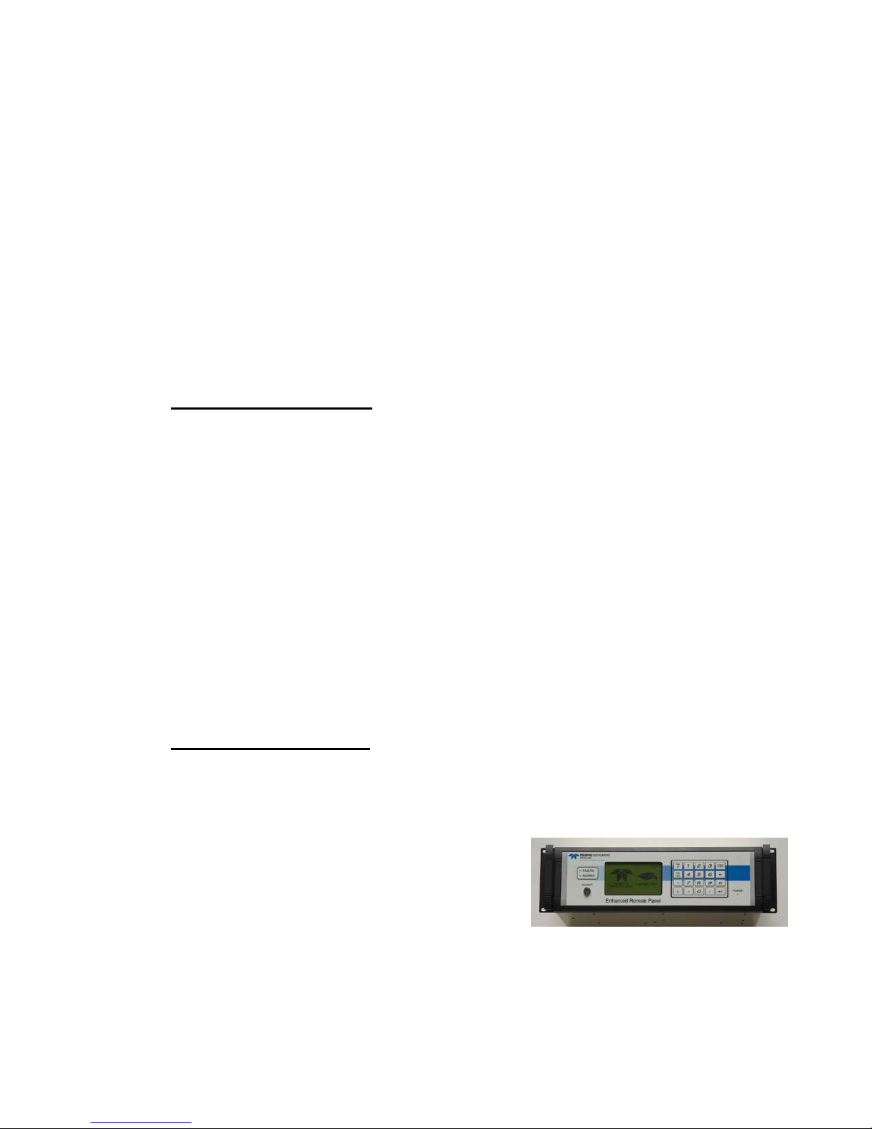
2.1.4 Enhanced Remote Panel
2.1.4.1 Enhanced Remote Display
The Enhanced Remote Display is built with a modular design. It is 19”
rack mountable. The software is menu driven and uses a commercial
network communications platform. It
uses a membrane switch keypad, a 4 ½”
Liquid Crystal Display (LCD) with
graphics capability and a key lockout for
critical functions.
2.1.4.2 Multi I/O Board
The Multi I/O Board is installed in the Enhanced Remote Panel chassis
and has eight relay outputs, eight digital inputs, and four individually
2-3

isolated analog outputs. The connections to the user interface devices
from the Multi I/O Board are made via connectors on the back panel of the
Enhanced Remote Display Panel.
2.1.4.3 Ethernet Module
The Ethernet Module is a single printed circuit board located inside of the
ERP chassis. External connection to the Ethernet Module is made via a
standard RJ45 connector socket in the rear panel of the ERP. The module
will provide web browser-based remote access, configuration and control
of the Ultraflow 150. At the same time the Ethernet Module can provide
HTML web pages for user interface and fast Modbus TCP access to
instrument data and parameters.
The details of this powerful ERP feature are described in its own
instruction manual which is provided with the instrument. The customer
supplied network cable may be installed into the socket marked “Ethernet”
at the right hand side of the ERP rear panel.
This option can be supplied in a standalone version for users who
purchased the 560DI.
SECTION 2.0, SYSTEM OVERVIEW
2-4

ULTRAFLOW 150 GAS FLOW AND TEM P ER ATURE MONITOR
3.0 OPTIONAL EQUIPMENT
The components listed below are optional on the Ultraflow 150 system.
They are not included on a standard system. Please consult the Site
Specification Data sheets in the back of this manual for the details of your
particular system.
Protective Purge Air System, Dual
Local User Interface Key Pad and Display
Dual Analog Input Board
Link Rod
6PT I/O PC Board Option
3.1 PROTECTIVE PURGE AIR SYSTEM, (DUAL)
The Dual Protective Purge Air System consists of two blowers and
weather covers designed to supply purge air to each Purge Nozzle
assembly. This configuration uses separate purge blowers to provide
clean purge air to each of the two Purge Nozzle Assemblies. This option
can be employed where the effluent pressures are very positive and is used
on all standard long range installations.
Consult the Site Specification Data sheet of Appendix A for information on
the configuration of your individual monitor
3.2 LOCAL USER INTERFACE KEY PAD AND DISPLAY
The Local User Interface Key Pad and Display option provides an
operator interface capability at the Transducer Interface Enclosure (TIE)
on the stack. This is a Local User Interface that will provide the ability to
evaluate the operation and setup variables of the system from the TIE
location.
This assembly contains a 6 character, 7 segment display and a keypad. The
two leftmost characters are GREEN while the 4 remaining characters to
the right are RED. The display is organized so that the 2 GREEN
characters indicate the software bank location of data, operational
variables, markers or configuration modifiers. The 4 RED characters to
the right hold the value of the data, status or marker in that bank location.
The locations are organized into different categories or BANKs of data
and parameters. The leftmost GREEN letter character describes the
3-1

BANK or category of display information, while the second GREEN
numeric character identifies the individual memory location within the
BANK.
Consult the Site Specification Data sheet of Appendix A for information on
the configuration of your individual monitor.
3.3 DUAL ANALOG INPUT BOARD
The Dual Analog Input Board option is required when the user wishes to
have the Ultraflow 150 take in external information on stack pressure and
temperature in order to convert the stack flow volume values to standard
conditions.
3.3.1 Barometric Pressure Sensor Assembly
A Barometric Pressure Sensor Assembly is available for the purpose of
correcting flow volume data to standard pressure. The assembly contains
an on-board absolute pressure transducer that reads the ambient pressure
outside the Transducer Interface Enclosure via a sealed vent line. This
approach is recommended only for applications in which the static gage
pressure of the process is not likely to undergo dramatic changes. For
cases where static pressure varies widely, a pressure transducer measuring
the actual process pressure will deliver maximum accuracy. See the
System Properties Menu section (Section 6.0) of this manual for external
pressure transducers.
SECTION 3.0, OPTIONAL EQUIPMENT
The Barometric Pressure Sensor Assembly is inserted into a connector on
the Dual Analog Input Board, a separate option located in the Transducer
Interface Enclosure. The Dual Analog Input Board provides the required
operating power for the assembly and converts the pressure transducer
voltage to 12 bit digital data for use by the Flow Mother Board.
Consult the Enhanced Remote section (Section 6.0) of this manual for
information on calibration of the Barometric Pressure Sensor Assembly.
See Table 3-1 below for the Dual Analog Input Board jumper settings for
use of the Barometric Pressure Sensor Assembly.
3-2

ULTRAFLOW 150 GAS FLOW AND TEM P ER ATURE MONITOR
DESCRIPTION
JUMPER
NUMBER
LABEL
POSITION
WIRING
Barometric Pressure Assembly
JU2
Don’t
Care
Don’t Care
None
JU3
INT
1-2
4-20mA Pressure Transmitter
JU2
CUR
1-2
J4 Terminals
1(+) and 2(-)
JU3
EXT
3-4
0-5VDC Pressure Transmitter
JU2
VOL
3-4
J4 Terminals
3(+) and 2(-)
JU3
EXT
3-4
Table 3-1
Dual Analog Input Board Jumpers for Pressure Input
3.3.2 External Temperature Measurement
The Ultraflow 150 can measure medium temperature in two manners:
INTERNAL MEDIUM TEMPERATURE: This measurement uses the
speed of sound data derived from the time of flights between the
upstream and downstream ultrasonic transducers. Since speed of
sound is directly proportional to the square root of absolute
temperature, a temperature measurement can be made based on this
data provided the concentrations of the major constituent gases
(usually O2, CO2, H20 and N2) are either relatively constant or
change predictably as a function of speed of sound. Examples of
applications where this is true include flow monitoring of single fuel
utility boiler stack gas emissions, cement kiln combustion emissions,
secondary combustion air and process steam boiler emissions.
EXTERNAL MEDIUM TEMPERATURE : This measurement utilizes
external, non-ultrasonic sensors to establish medium temperature.
This technique is recommended when the concentrations of the major
constituent gases (usually O2, CO2, H20 and N2) change
unpredictably or are not a function of speed of sound. In these cases,
the absolute values of the Ultraflow 150’s INTERNAL MEDIUM
TEMPERATURE will be inaccurate by magnitudes roughly
proportional to the change in molecular weight. An example of such an
application is a multi-fuel (i.e., one that can run on coal or natural gas
at base load) utility boiler.
The Dual Analog Input Board option is required to implement the
EXTERNAL MEDIUM TEMPERATURE option. The Dual Analog
Input Board is compatible with a variety of external temperature sensors:
1000 ohm 2 wire RTD’s (see the next sub-section of this manual), 4 – 20
mA and 0 to 5 Volt. Thermocouples are not supported. See the System
Properties Menu section (Section 6.0) of this manual for information on
calibration of EXTERNAL MEDIUM TEMPERATURE devices.
3-3

JUMPER
OPTIONS
DEFAULT
FUNCTION
JU1
RTD = 1-2
VOL = 5-6
RTD = 1-2
Selects external input to
RTD, 1-5 volts, or 4-20 mA
JU4
3-4 (1000 ohms)
3-4 (1000 ohms)
Selects the 32°F (0°C) RTD
resistor for calibration
JU7
3-4 (1000 ohms)
3-4 (1000 ohms)
Selects the 1000 ohm RTD
for operations
3.3.2.1 Resistive Temperature Device (RTD)
An optional Resistive Temperature Device (RTD) probe is available for
use as an EXTERNAL MEDIUM TEMPERATURE sensor. The heart of
the assembly is a 1000 ohm 2 wire RTD. Consult the system wiring
diagram for connection of the RTD Assembly to the TIE.
The optional Dual Analog Input Board is required to use the RTD
assembly. See Table 3-2 for the applicable Dual Analog Input Board
jumper settings for the assembly.
Table 3-2
Dual Analog Input Board Jumpers for External Temperature
SECTION 3.0, OPTIONAL EQUIPMENT
3.4 LINK ROD
For stacks with an annulus or thick outer walls that must be bridged by the
Ultraflow 150 Purge Nozzle Assemblies, Teledyne Monitor Labs offers
the Link Rod option whenever the Purge Nozzle Assemblies would exceed
72 inches (183 cm) in length. Beyond this length, the standard assemblies
become unwieldy and are difficult to align in the center of their ports. The
Link Rod Assemblies replace the standard Purge Nozzles. The Link Rod
Assemblies consist of a transducer housing with skids to center it in the
port, and a series of short rods that connect or disconnect as the transducer
housing is inserted or removed from the port. The Link Rod option also
reduces the amount of removal clearance required to extract the
transducers for maintenance and cleaning. This mounting option is
complete with all hardware, flanges and seals.
CUR = 3-4
temperature channel between
Consult the Site Specification Data sheet of Appendix A for information on
the configuration of your individual monitor.
3-4

ULTRAFLOW 150 GAS FLOW AND TEM P ER ATURE MONITOR
Number
2
Isolation Type
Optical & capacitive barriers; channel to channel, channel
to circuit common & earth
Minimum Isolation Voltage
500Vpeak*, 500VDC*
Output Type
4-20mA with live 4mA zero, OR 0-20mA w/o live zero
Maximum Load Resistance
900 ohms
Maximum Offset
±0.05% of full scale
Total Output Error
±0.30% of full scale
Number
2
Modes
Isolated and Non-isolated
Isolated Mode Minimum Isolation
Voltage
500Vrms*
Isolated Mode Minimum Actuation
Voltage
5VDC (user supplied)
Isolated Mode Maximum Actuation
Voltage
24VDC (user supplied)
Isolated Mode Maximum Input Current
50mA @ 24VDC
Non-Isolated Mode Actuation
Condition
Dry contact closure
Non-Isolated Mode Internal
Operating Voltage
5VDC
Number
2 SPST, N.O. (Single Pole Single Throw, Normally Open or
Normally Closed [jumper selectable])
Minimum Isolation
Maximum Contact Voltage
250VAC
Maximum Contact Current
1Amp AC, 1Amp DC
3.5 6PT I/O PC BOARD OPTION FOR 150DI
The Six Point I/O Board is an optional device intended to provide a low
cost Direct Interface feature to the Ultraflow 150DI where analog output
and control signals are supplied directly from the Transducer Interface
Enclosure (TIE) Assembly. The PC Board has 2 analog outputs, 2 digital
inputs and 2 relay outputs. The Local User Interface Key Pad and Display
option comes standard with the 6PT I/O option. The configuration of the
6PIO Board is software selectable using the PC to Modbus interface
software supplied with the Ultraflow 150DI. Below are the specifications.
The details on this option are described in its own instruction manual.
Six Point I/O Board Specifications
SIX POINT I/O BOARD ANALOG OUTPUTS
SIX POINT I/O BOARD DIGITAL INPUTS
SIX POINT I/O BOARD RELAY OUTPUTS
500Vrms*
*I/O wires with respect to earth (common mode).
3-5
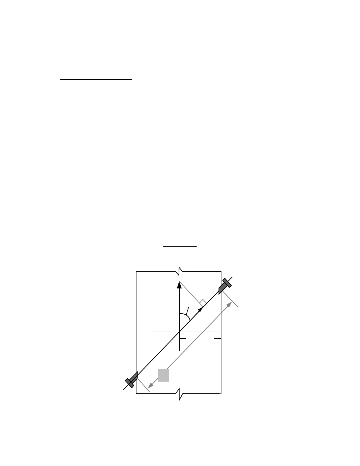
4.0 THEORY OF OPERATION
Upstream
Transducer
L
θ
(Actual)
Fv
(Nominal)
Fv
Ft
Downstream
Transducer
4.1 PHYSICS OF MEASUREMENT
4.1.1 Time of Flight Theory
The Ultraflow 150 system measures the transit times of ultrasonic tone bursts
through the gas stream to determine flow velocity, temperature, and volume.
Each effluent path monitored by the Transducer Interface Enclosure (TIE) uses
two transducers placed on opposite sides of the stack or duct (see Ultraflow 150
System Installation Drawing, Appendix D). The transducers are pointed at each
other with one transducer located diagonally upstream from the other. Each
transducer acts alternately as a transmitter or receiver with the ultrasonic waves
passing through the centroid of the stack or duct to the other transducer. This
makes the measurements a line average of the tone burst path length. When a
tone burst is sent through the gas stream from the upstream transducer to the
downstream transducer the movement of the gas stream reduces the time required
to traverse the distance. When the tone burst is traveling against the gas stream
from the downstream to the upstream transducer, the traverse time is increased.
When there is no gas flow, the time required for the ultrasonic tone bursts to
traverse the gas stream in either direction is the same. Both the upstream and
downstream transit times are measured by the Transducer Interface Enclosure to
an accuracy of 0.5 microseconds.
SECTION 4.0, Theory of operation
Figure 4-1
Transit Time Theory
4-1

ULTRAFLOW 150 GAS FLOW AND TEM P ER ATURE MONITOR
4.1.1.1 Flow Velocity Measurement
The root measurement of the Ultraflow 150 is transit time. The difference
between upstream and downstream transit times through the gas stream is directly
proportional to the velocity of the gas stream. From transit time and the following
physical equations the TIE calculates flow velocity. This velocity measurement is
inherently independent of the temperature, density, viscosity, and particulate
concentration since these terms drop out of the simplified equations.
1)
Velocity of Sound from Upstream to Downstream Transducer
2)
Velocity of Sound From Downstream to Upstream Transducer
Where:
Cs = The Speed of Sound
Fν = Flue Gas Velocity
θ
= Transducer Angle to Flow
V = Velocity of Respective Tone Bursts
3) Subtract equations 1 & 2:
and solving for Fν:
4)
substituting
5)
Fν is the Line Average Velocity.
And: t = Transit times of sound between the transducers
L = Distance between the transducers
4-2

4.1.1.2 Temperature Measurement
By knowing the precise time required for the tone bursts to traverse the gas stream
the speed of sound is calculated. The influence on the speed of sound resulting
from temperature change is well established. Therefore, the gas stream
temperature measurement may be calculated directly from the speed of sound
determination. This measurement will remain accurate so long as the gas
composition is from a single fuel source or remains relatively consistent in terms
of its molecular weight.
If multi-fuel operation is expected, the Ultraflow 150 should be configured using
an external temperature device that may be facilitated using the optional Dual
Analog Input Board.
Consult the Site Specification Data sheet of Appendix A for information on the
configuration of your individual monitor
4.1.2 Flow Volume Measurement
Once the flow velocity (Fν) has been determined it is multiplied by the crosssectional area of the stack or duct to determine the actual volumetric flow. The
units may be English or Metric, per hour, minute or second, according to a
software selection.
SECTION 4.0, Theory of operation
4.1.3 Wet Basis and Dry Basis Measurements
The Ultraflow 150 gives a wet basis reading only. A wet basis measurement is
one that includes the water vapor component of the effluent in the measurement.
A dry basis measurement is one that removes the water vapor and makes the
measurement on the remaining components of the effluent.
4.1.4 Correction to Standard Temperature and Pressure
Effluent pressure and temperature can vary dramatically from one process to
another. For the sake of uniform reporting most regulatory applications require
the volume and mass flow to be reported in standard pressure and temperature
units. To do this, the monitor’s measurement must be corrected according to the
ideal gas law for the agency specified pressure and temperature. US EPA
standard (reference) conditions are 680 F and 29.92 in. Hg for English units and
200 C and 101.32 Kpa for metric units. The Ultraflow 150 has the ability to take
inputs from an external pressure transducer and a temperature device. The
monitor’s internal temperature measurement may also be used for correction.
Each correction factor can be turned on or off individually to accommodate
systems that do these functions elsewhere.
4-3

ULTRAFLOW 150 GAS FLOW AND TEM P ER ATURE MONITOR
×=
×
Actual
Ref
Ref
Actual
ActualStandard
T
T
P
P
FlowFlow
To convert actual flow volume to standard flow volume:
NOTE: The temperature must be in absolute terms Eg. 459.69 + deg
4.2 MONITOR SPECIFIC THEORY
4.2.1 Box Car Integration
At the heart of the Ultraflow 150 is a signal conditioning technique known as
“Boxcar Integration”. Each time a tone burst traverses the stack a 16 millisecond
window of interest within the receive signal is digitized by an A/D converter in
0.5 microsecond intervals. This results in a window of interest composed of
32,768 digital values or “boxcars”. For each tone burst during the integration
period the value of each boxcar is added to the sum of all previous boxcars having
the same location in the window. For example on the fourth tone burst of the
integration period, the value of boxcar #100 will be added to the sum of the three
previous boxcar #100s. This technique greatly enhances the signal to noise ratio.
The true receive signals occur at virtually the same time (boxcar) for each tone
burst in the average period and are always positive thus add up faster than the
background noise which is random in time.
At the end of the integration period the resulting window of 32,768 data bits is
sent through the digital signal processing algorithms and the boxcar integrator
reset for the next integration period. The signal processing algorithms determine
the center of the receive signal and thus the exact transit time across the stack.
f
4.2.2 Operational Modes of the Transducer Interface Enclosure
4.2.2.1 NORMAL Mode
During the NORMAL mode the transducers of each transducer pair are alternately
transmitting and receiving signal through the medium and performing the gas
stream velocity calculations. The mode code for NORMAL mode is 1. During
NORMAL mode the TIE cycles the transmit pulses to the transducers on a round
robin basis so there are never any two transducers transmitting or receiving at the
same time. If only one path (transducer pair) is being used, the upstream and
downstream transducers will alternate. The TIE processes and reports the data at
the end of each integration period.
4-4

SECTION 4.0, Theory of operation
4.2.2.2 ZERO Calibration
The mode code for ZERO mode is 4. During the ZERO mode the TIE processes
the signals in a slightly different manner. When both a ZERO and SPAN
calibration have been completed, a comprehensive full system evaluation check
has been done. During ZERO, only the upstream transducer transmits and it
transmits at twice the normal rate. The downstream transducer is receiveing only.
The TIE‘s electronics process each pair of signals as though they were typical
upstream and downstream signals. Since all ZERO mode receive signals go
through the gas stream in the same direction, the time required to traverse the gas
stream should be essentially the same. With no difference in the transit times, the
flow should indicate zero velocity. Small fluctuations in the upstream transmit
and downstream receive properties will indicate non-zero flow readings.
4.2.2.3 SPAN HIGH Calibration Mode (Upscale Calibration)
The mode code for SPAN HIGH mode is 2. During SPAN HIGH only the
downstream transducer transmits and it transmits at twice the normal rate. The
upstream transducer is receiving only. The TIE’s electronics process each pair of
signals as though they were upstream and downstream signals. This would be
expected to produce another zero flow indication. However, in the "SPAN
HIGH" mode every other received tone burst is delayed by a predetermined
amount. This means that the TIE sees a difference in the time required for the
upstream and downstream tone bursts to traverse the gas stream. Small
fluctuations in the downstream transmit and upstream receive properties or
electronics shifts will show changes in the expected flow readings.
4.2.2.4 SPAN LOW Calibration Mode
The mode code for SPAN LOW mode is 3. During SPAN LOW mode the TIE
controls the transducers and processes the signals in the same way as in the SPAN
HIGH mode except that the calculated delay for every other receive signal is
shorter. This gives a shorter transit time difference, thus a lower expected flow
volume.
4.2.2.5 Acquire Modes
There are four Acquire Modes, NORMAL Acquire = 5, SPAN HIGH Acquire =6,
SPAN LOW Acquire = 7, and ZERO Acquire = 8. Acquire modes are invoked
during transitions from one mode to another. When the TIE changes modes, the
acquire for the requested mode will be indicated until the number of integration
periods needed for a good average has been reached. For example if the number
of integration periods per normal average is set to 4 and a mode change to ZERO
mode initiated, the TIE will indicate ZERO Acquire mode for 4 integration
periods before switching to ZERO mode for the balance of the calibration periods.
NOTE: The number of periods for a calibration average must be equal to or
larger than the number for a normal average.
4-5

ULTRAFLOW 150 GAS FLOW AND TEM P ER ATURE MONITOR
(This page intentionally left blank.)
4-6
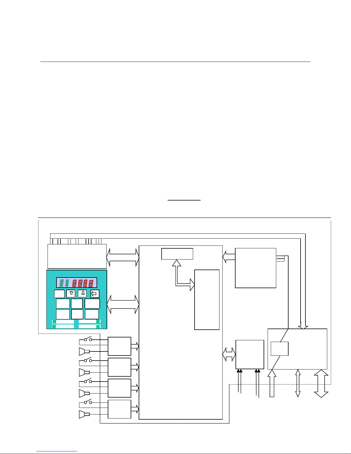
SECTION 5.0, TRANSDUCER INTERFACE ENCLOSURE
Flow
Four DB
Connectors,
SPI
Power
68332
Computer
Module
Optional
Version Only}
2 Discrete Isolator 2 Relay 2 4-20mA
. Inputs Outputs Analog Outputs
Power Supply
Mains
Voltage
Dual
Input Board
{optional}
Preamp /
Board
Purge
Switch
Transducer
Purge
Switch
Transducer
Purge
Switch
Transducer
Purge
Switch
Transducer
Preamp /
Board
Preamp /
Board
Preamp /
Board
Field wiring
Network
remote
RS232 Serial
Port
SPI
SPI
External
Interface Board
Disp
High
Normal
Low
E
Optional Keypad / Display
5.0 TRANSDUCER INTERFACE ENCLOSURE (TIE)
The Transducer Interface Enclosure houses the electronics that control the stackmounted portion of the Ultraflow 150. Each Ultraflow 150 TIE has the ability to
monitor two separate paths on the same stack. The TIE will take a full set of
measurements from each path as well as calculate average values of the two paths
combined.
5.1 MECHANICAL DESCRIPTION
The Transducer Interface Electronics is enclosed in a stainless steel NEMA 4X
type enclosure. All cable entries in the enclosure are located in the bottom for
better seal integrity and are sized for ¾” conduit fittings. The cover is hinged on
the left side with screw down latches on the other three sides. Inside the
enclosure, all the electronics are mounted to a removable back plate. A field wire
terminal block board (External Interface Board) with power ON/OFF switch is
mounted to the right inside of the enclosure. Please see the assembly and
installation drawings in Appendix D.
Figure 5-1
Transducer Interface Enclosure Block Diagram
Six Point I/O Board
{Direct Interface
Zero
Path
Driver
Analog
Power
switch
5-1
Driver
Driver
Driver
SPI and analog
Stack
Pressure
Stack
Temperature
wires to
for optional
I/O

ULTRAFLOW 150 GAS FLOW AND TEM P ER ATURE MONITOR
5.2 ELECTRICAL DESCRIPTION
The TIE can be powered with either 115 VAC or 230 VAC feeds. The power
supply is auto ranging and will function normally with inputs from 85 VAC to
265 VAC, 50-60HZ. The power ON/OFF switch is located inside on the External
Interface Board. This board’s main purpose is to provide a place to land the field
wiring. The terminal blocks are sized to handle 12 – 28 AWG wire.
The data cable to the Enhanced Remote Panel uses shielded two-wire cable to
carry the serial data via a commercial communication protocol. The signals to
and from each of the transducer probes are carried by a RG62 coax cable and a
multi pair, individually shielded, 22 AWG, cable carries the purge on/off signal.
5.2.1 External Interface PC Board
The main purpose of the External Interface PC Board is to provide a connection
point for the field wiring. It has three terminal blocks. TB1 is for landing the AC
mains and TB2 is used to land the data cable network wires. If the optional Direct
Interface (560DI) is incorporated into the system, the unused terminals of TB2
and all of TB3 are used to land the interface wires. A double pole power ON/OFF
switch is also located here. The board has direct connections to the Power Supply
Board, Flow Mother Board, and optional Six Point I/O Board.
Consult the Site Specification Data sheet of Appendix A for information on the
configuration of your individual monitor.
5.2.2 Power Supply Board
The Power Supply Board is located in the upper right corner of the enclosure. It
plugs directly into the Flow Mother Board. The power supply is auto ranging. It
requires 85-265 VAC, 50-60 HZ input power and provides +15 VDC regulated, 15 VDC regulated, and +5 VDC regulated outputs.
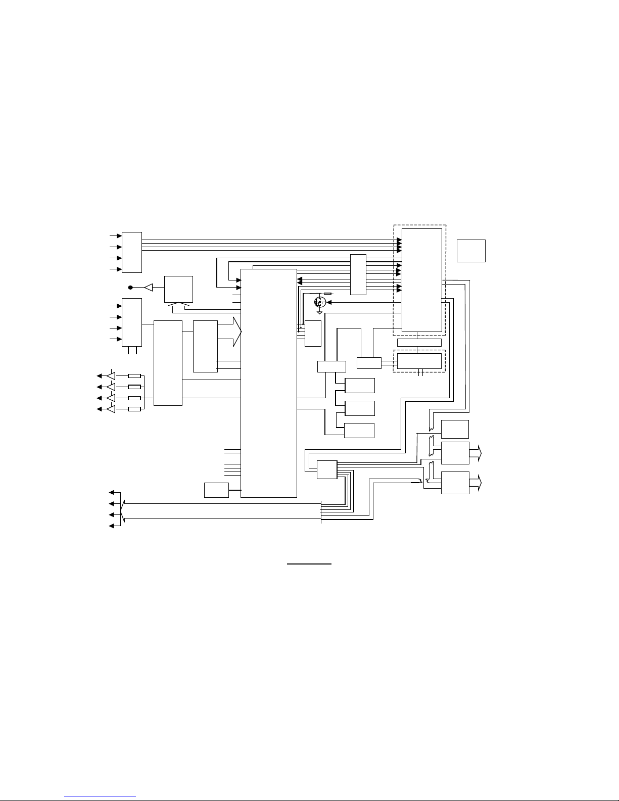
5.2.3 Flow Mother Board
At the heart of the Flow Mother Board are two control devices a Field
Programmable Gate Array (FPGA) and a self-contained computer processor
module. The FPGA performs all of the low-level control functions of the
transducer interface. The computer module is a stand alone, SBC 332 Processor
Board that plugs directly into the Flow Mother Board. The computer module
handles all calculations and higher level control/timing. Please refer to Fig 5-2.
The Flow Motherboard architecture is complex, as is the custom application
software it runs. A detailed description of the board’s electronics and software is
beyond the scope of this manual. For ease of understanding, the Mother Board’s
function is described on a block diagram level.
5-2
SECTION 5.0, TRANSDUCER INTERFACE ENCLOSURE
150BlockDiagram.ppt
21 Feb. 2001
ELM
FPGA
4
Channel
Mux
12 bit
Parallel
2MSPS
ADC
ADS803
12 MHz
Oscillator
Dual 8 Bit
Parallel
Multiplying
DAC
TLC7528
From P r e a mp
Purge Switch
Circuits
From P r e a mp
Analog
Output
Circuits
To
Prea mp
Transmit
Drive
Input
Circuits
To Preamp
AGC DAC’s
(1 per
Prea mp)
Start Start ADC
Gain Bus &
Waveform
Data
(8 Data & 3
Control
Lines)
Channel
Selects
SPI Clock, Input and Output Data Lines, 4 SPI Slave Selects
Wait / Measure*
Serial
Configuration
Inpu ts
Measur e ment Co mp l ete
Config
Device
3.3V Bus
Xcvr ’s
D0 to D15, R/W
A0 to A18,
CS6,7,9,10
IRQ5
TPU
I/O
TPU I/O
SBC332 Board
ADC
Data
Input
D0 to D15,
A0 to A18,
CS6,7,9,10,
R/W
NEURON
Circuit
FTT10A
Network Wire s
Bus
Xcvr
Renew*
Real Time
Clock
DB
Connector
DB
Connector
To 6 Point
I/O
To Display
Control
128Kx8
SRAM
Buffer
&
ESD
Network
SPI
Clock
& Data
Sla ve
Selects
12 Bit
Parallel
DAC312
Test Point
(like TP4)
Diagnostic Output
12 lines
RESET Sync
A out
B out
To Channel Selects
128Kx8
SRAM
128Kx8
SRAM
TPU
I/O
1 of 4
Transmit Select
Binary Coded
Receive Select
Mode_1
Mode_2
CONFI G_DO NE
Boxcar Overflow
DIAG_0
DIAG_1
JUx
Logic 0 or 1
JUy
Logic 0 or 1
INIT_DONE
3.3V
Bus
Xcvr ’s
4 to 16
Decoder
Over -
ran ge
OVR
Boxc a r R AM B us y
RECONF IG
+3.3V
RS232
Port
DB
Connector
Figure 5-2
Flow Mother Board Block Diagram
5-3
ULTRAFLOW 150 GAS FLOW AND TEM P ERATURE MONITOR
TRANSDUCER TYPE
REQUIRED CONFIGURATION DEVICE U5
ES
Labeled as X.50
LR003
Labeled as X.20
LR004 through LR007
Labeled as X.14
5.2.3.1 Configuration Devices
The Flow Mother Board FPGA is SRAM-based; therefore its internal memory is
volatile. Consequently, it must be configured each time power is cycled. This is
done automatically with an IC known as a Configuration Device. The
Configuration Device U5 is a flash memory that contains additional circuitry to
control the serial loading of configuration data into the FPGA. The configuration
data in U5 programs the gates and registers inside the FPGA to accomplish the
board’s design functions. It is important to realize this configuration is not the
same as the monitor’s calibration configuration, i.e. parameters such as Geometry
Properties, Calibration Properties, etc., which are usually entered by menu
selections via the Enhanced Remote Panel software.
The FPGA performs digital filtering on the incoming received signals. Since each
transducer type has a different center frequency, a different Configuration Device
is required to properly filter each one. There are three different types of
Configuration Devices, one for each type of transducer. See Table 5-1.
Table 5-1
Configuration Device U5 versus Transducer Type
(where X is number that changes based on the firmwa re v ersion of U5)
In the Enhanced Remote, the System Properties, Intrinsic Properties parameter
Transducer Type can be selected via menu control. This selection must match the
Configuration Device U5 or the monitor will not function. A Filter Mismatch
fault will be generated if the Transducer Type selection does not match
Configuration Device U5.
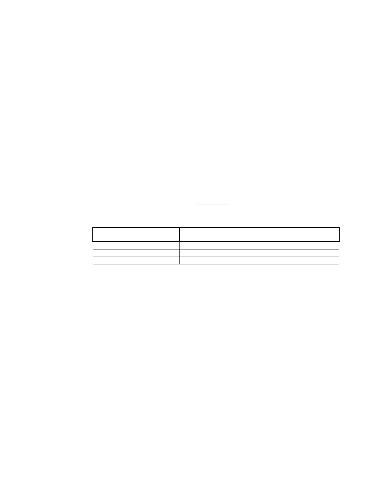
5.2.3.2 Transducer Drive Waveforms
The FPGA produces a digitized version of the ultrasonic tone burst wave packet
required to drive the transducers. The FPGA sends a digital representation of the
wave packet to the “B” half of a dual DAC where it is converted to an analog
signal and steered to the appropriate preamp by the transmit select signals of the
FPGA. Since this waveform is digitally created, it does not require tuning and is
virtually free of temperature drift. Figures 5-3A and 5-3B are examples of typical
waveforms for two different transducer types used in different applications.
Consult the Site Specification Data sheet of Appendix A for information on the
transducer configuration of your individual monitor.
5-4
SECTION 5.0, TRANSDUCER INTERFACE ENCLOSURE
-100
-80
-60
-40
-20
0
20
40
60
80
100
Figure 5-3A Figure 5-3B
100
80
60
40
20
0
-20
-40
-60
-80
-100
Note: The scales of the “X” axes are not the same.
5.2.3.3 Receive Signal Select, Gain, Digitization, Integration and Storage
When the FPGA determines it is time to read the receive signal from a particular
transducer/preamp it sends the appropriate channel select code to the four channel
multiplexer. The multiplexer then places the desired analog receive signal on the
input of the “A” half of a dual DAC. The DAC applies the appropriate gain that
is determined by the FPGA to this signal and places the result on the input of a
twelve bit Analog to Digital converter (ADC). The ADC begins doing a
conversion when it receives a start signal from the FPGA. Each conversion takes
0.5 µsec. At the end of each conversion the digital value is passed to the FPGA
where it is filtered, rectified, and added to the appropriate boxcar in the RAM.
Another start signal is then issued and the ADC starts another conversion cycle.
This continues for 32,384 cycles creating a sixteen millisecond wide window of
0.5 µsec filtered digital averages. The RAM has a separate boxcar window for
each transducer. After the digitized window is complete the FPGA channel select
requests a different transducer/preamp signal from the multiplexer and the ADC
conversions begin forming the digital, (boxcar) window for that transducer. The
channel select continues cycling through the transducers and adding conversions
to the boxcars in the window until the desired integration time is over. This is
typically 30 seconds. At the end of the integration period the FPGA sends a
“Measurement Complete” signal to the 332 Processor. The 332 Board issues a
5-5
“Wait” signal to the FPGA, while it reads the four windows of “Boxcar” data, and
processes the data into time measurements and velocity readings. Then it begins
the next sampling cycle for the duration of the integration period.
ULTRAFLOW 150 GAS FLOW AND TEM P ERATURE MONITOR
DIAG_2
(JU8C)
DIAG_1
(JU8B)
DIAG_0
(JU8A)
0 0 0
A/D Output
0 0 1
Filter ABS
0 1 0
Boxcar (6--17)
0 1 1
Boxcar (7--18)
1 0 0
Boxcar (9--20)
1 0 1
Boxcar (10--21)
1 1 0
Boxcar (11--22)
1 1 1
Boxcar (12--23)
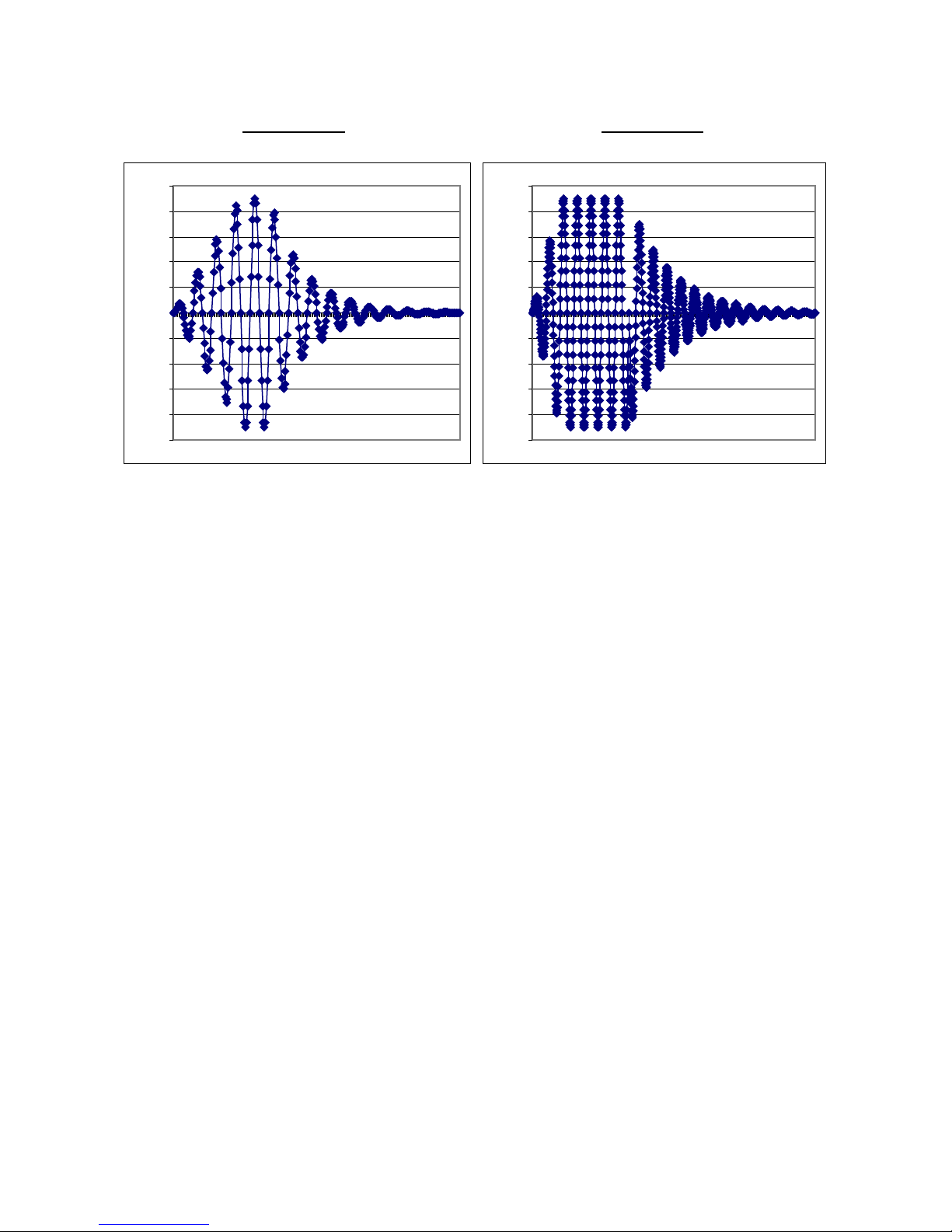
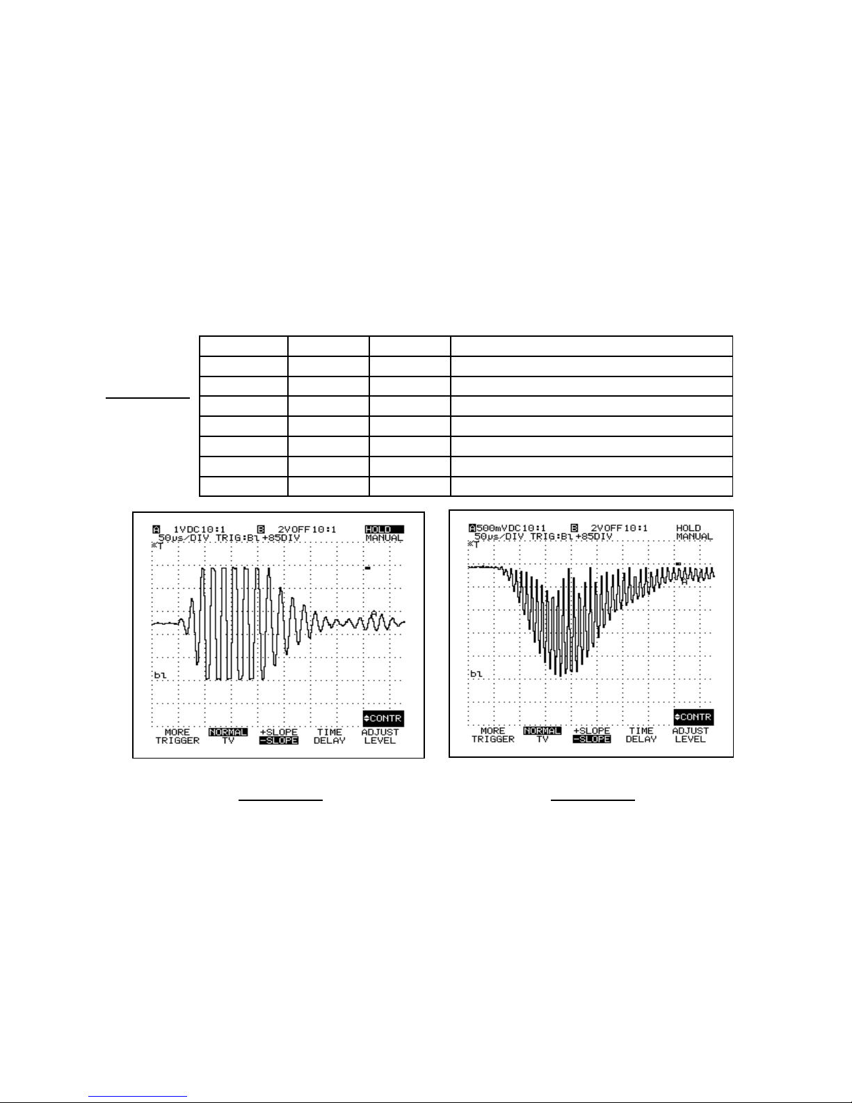
Figure 5
Typical filtered, absol ut e value waveform
Typical A/D output waveform, Normal
5.2.3.4 Diagnostic Waveforms Circuit
The Flow Mother Board has an important built in diagnostic feature. Eight
different signals can be viewed from test point 21 (TP21) depending on the
configuration of the diagnostic jumpers of JU8. The FPGA places the digital data
selected by JU8 (positions A, B or C) on a twelve-bit buss that connects to a
digital to analog converter (DAC). The DAC sends an analog representation of
the data through a buffer to TP21. This gives the user a way to view complex
data such as the filtered and integrated receive data that exists only in the digital
realm.
-4A
Diagnostic Output
Figure 5-4B Figure 5-4C
Note: The sample diagnostic waveforms above were taken from TP21 during normal
mode with the scope triggered on TP34.
5.2.3.5 Bus Transceivers and Logic Level Differences
The digital components of the Flow Mother Board operate with three different
logic levels. The FPGA’s internal logic uses 2.5 VDC. Its I/O logic requires 3.3
VDC. The SBC 332 Processor and Neuron Circuit use conventional 5.0 VDC
5-6
 Loading...