

Teledyne RIVERPRO, RIOPRO User Manual
RIVERPRO & RIOPRO
ADCP GUIDE
Information included herein is controlled by the Export Administration Regulations (EAR) and may
require an export license, license exception or other approval from the appropriate U.S. Government
agency before being exported from the United States or provided to any foreign person. Diversion
contrary to U.S. law is prohibited.
P/N 95B-6097-00 (October 2017)
© 2017 Teledyne RD Instruments, Inc. All rights reserved.

Page ii
EAR-Controlled Technology Subject to Restrictions Contained on the Cover Page.

TABLE OF CONTENTS
CHAPTER 1 - AT A GLANCE ...................................................................................................................................1
RiverPro/RioPro Inventory ........................................................................................................................... 2
RiverPro Overview ....................................................................................................................................... 3
RioPro Overview........................................................................................................................................... 4
Boat Overview .............................................................................................................................................. 5
Computer Overview ..................................................................................................................................... 5
Power Overview ........................................................................................................................................... 6
Auto-Adaptive Water Profiling Mode .......................................................................................................... 6
RiverPro/RioPro Options ...................................................................................................................... 6
Setting up the RiverPro/RioPro System ....................................................................................................... 8
Bluetooth Connection .......................................................................................................................... 8
Serial Connection ................................................................................................................................. 11
Connecting to the RiverPro/RioPro ................................................................................................ 12
Changing the Baud Rate in the ADCPs ........................................................................................... 14
RiverPro/RioPro Recorder ............................................................................................................................ 15
Enabling the Loop Recorder ................................................................................................................. 15
Recovering Data from the Loop Recorder ............................................................................................ 15
Erasing Data from the Loop Recorder .................................................................................................. 16
Caring for the RiverPro/RioPro System ........................................................................................................ 17
General Handling Guidelines ................................................................................................................ 17
Assembly Guidelines ............................................................................................................................ 17
Deployment Guidelines ........................................................................................................................ 17
CHAPTER 2 - INSTALLATION ..................................................................................................................................19
Attaching the Boat Mounting Plate .............................................................................................................. 20
Boat Assembly .............................................................................................................................................. 21
Boat Battery Connection .............................................................................................................................. 22
I/O Cable and Dummy Plug .......................................................................................................................... 23
Using the Cable Clips ............................................................................................................................ 24
Routing Cables...................................................................................................................................... 25
Cable Wiring Diagram .................................................................................................................................. 26
Mounting the Instrument ............................................................................................................................ 27
Over-the-Side Mounting ...................................................................................................................... 28
In-Hull Mounting .................................................................................................................................. 29
CHAPTER 3 – COLLECTING DATA ............................................................................................................................31
RiverPro/RioPro Operation Overview .......................................................................................................... 32
Glossary ................................................................................................................................................ 33
Prepare for Discharge Measurement ................................................................................................... 33
Measurement Wizard .................................................................................................................... 34
Run Built-In Tests ........................................................................................................................... 34
Compass Calibration ...................................................................................................................... 34
Moving Bed Test ............................................................................................................................ 34
Locating the Start and Stop Positions................................................................................................... 35
Discharge Measurement .............................................................................................................................. 35
Moving Boat Discharge Measurement ................................................................................................. 35
Stationary Discharge Measurement ..................................................................................................... 36
CHAPTER 4 - MAINTENANCE .................................................................................................................................37
Parts Location Drawings ............................................................................................................................... 38
Maintenance Schedule ................................................................................................................................. 40
Calibration Items .................................................................................................................................. 40
Maintenance Items .............................................................................................................................. 40
Periodic Maintenance Items ........................................................................................................................ 41
I/O Cable Connector Lubrication .......................................................................................................... 41
Page iii
EAR-Controlled Technology Subject to Restrictions Contained on the Cover Page.

Cleaning the I/O Cable Connectors ...................................................................................................... 42
Cleaning the Temperature Sensor Cover ............................................................................................. 42
Removing Biofouling ............................................................................................................................ 42
Final Storage or Shipping Preparation .................................................................................................. 43
Calibrating the Compass....................................................................................................................... 43
Calibrating the Compass with WinRiver II ...................................................................................... 43
Yearly Maintenance Items ........................................................................................................................... 45
Maintenance Kit ................................................................................................................................... 45
End-Cap Removal Procedures .............................................................................................................. 49
Transducer Head Assembly Removal ................................................................................................... 49
RiverPro/RioPro Re-assembly ...................................................................................................................... 50
Desiccant Bags ...................................................................................................................................... 50
O-ring Inspection and Replacement ..................................................................................................... 51
Transducer Head Assembly Replacement ............................................................................................ 52
End-cap Replacement .......................................................................................................................... 53
CHAPTER 5 – TESTING TH E RIVERPRO/RIOPRO .........................................................................................................55
Testing the System using WinRiver II ........................................................................................................... 56
Testing the System with SxS Pro .................................................................................................................. 57
Testing the System with BBTalk ................................................................................................................... 57
Test Results .................................................................................................................................................. 58
Display System Parameters .................................................................................................................. 58
Instrument Transformation Matrix ...................................................................................................... 58
Pre-deployment Test ............................................................................................................................ 59
Display Heading, Pitch, Roll, and Voltage ............................................................................................. 59
CHAPTER 6 - TROUBLESHOOTING ...........................................................................................................................61
System Status and LED Behavior .................................................................................................................. 62
Fuse Replacement ........................................................................................................................................ 63
Boat Wiring Diagram .................................................................................................................................... 64
CHAPTER 7 - RETURNING SYSTEMS TO TRDI FOR SERVICE ............................................................................................65
Shipping the RiverPro/RioPro....................................................................................................................... 66
Returning Systems to the TRDI Factory ........................................................................................................ 67
Returning Systems to TRDI Europe Factory .................................................................................................. 68
CHAPTER 8 - SPECIFIC ATIONS ................................................................................................................................71
Outline Installation Drawing ........................................................................................................................ 74
CHAPTER 9 - COMMANDS ....................................................................................................................................77
Data Communication and Command Format .............................................................................................. 78
Command Input Processing ................................................................................................................. 78
Data Output Processing........................................................................................................................ 79
Firmware Updates ........................................................................................................................................ 79
Feature Upgrades ......................................................................................................................................... 80
Command Summary ..................................................................................................................................... 81
Command Descriptions ................................................................................................................................ 84
? – Help Menus .............................................................................................................................. 84
Break .............................................................................................................................................. 85
OL – Display Feature List ................................................................................................................ 86
Y – Display Banner ......................................................................................................................... 86
Bottom Track Commands ............................................................................................................................. 87
Available Bottom Track Commands ..................................................................................................... 87
Bottom Track Command Descriptions ................................................................................................. 87
BP – Number of BT Pings ............................................................................................................... 87
BX – Maximum Tracking Depth ...................................................................................................... 88
Control System Commands .......................................................................................................................... 89
Available Control System Commands .................................................................................................. 89
Control System Command Descriptions ............................................................................................... 89
Page iv
EAR-Controlled Technology Subject to Restrictions Contained on the Cover Page.

CA – Communication Timeout ....................................................................................................... 89
CB – Serial Port Control .................................................................................................................. 90
CF – Set Control Flags..................................................................................................................... 91
CK – Save Command Parameters to Flash ..................................................................................... 92
CR – Restore Command Defaults ................................................................................................... 92
CS – Start Pinging (Go) ................................................................................................................... 93
CState – Pinging State Query ......................................................................................................... 93
CStop – Stop Pinging ...................................................................................................................... 93
CT – Turnkey Mode ........................................................................................................................ 93
CW – Output the Last Stored Ensemble ......................................................................................... 94
CZ – Put the system to sleep .......................................................................................................... 94
Environmental Commands ........................................................................................................................... 95
Available Environmental Commands ................................................................................................... 95
Environmental Command Descriptions ................................................................................................ 95
EA – Heading Alignment ................................................................................................................ 95
EB – Heading Bias ........................................................................................................................... 96
EC – Speed of Sound ...................................................................................................................... 96
ED – Depth of Transducer .............................................................................................................. 97
EH – Heading .................................................................................................................................. 97
EP – Pitch (Tilt 1) ............................................................................................................................ 98
ER – Roll (Tilt 2) .............................................................................................................................. 98
ES – Salinity .................................................................................................................................... 98
ET – Temperature .......................................................................................................................... 99
EU – System Orientation ................................................................................................................ 99
EX – Coordinate Transformation .................................................................................................... 100
EZ – Sensor Source ......................................................................................................................... 103
Recorder Commands .................................................................................................................................... 104
Available Recorder Commands ............................................................................................................ 104
Recorder Command Descriptions......................................................................................................... 104
ME – Erase Recorder ...................................................................................................................... 104
MM – Show Memory Usage .......................................................................................................... 105
MN – Set File Name ....................................................................................................................... 105
MR – Set Recorder On/Off ............................................................................................................. 105
MQ – Streaming Download ............................................................................................................ 106
MY – Y-Modem output .................................................................................................................. 106
Performance and Testing Commands .......................................................................................................... 107
Available Performance and Testing Commands ................................................................................... 107
Performance and Testing Command Descriptions ............................................................................... 107
PA – Run Go/No-Go Tests .............................................................................................................. 107
PC – User Interactive Built-In Tests ................................................................................................ 108
PD – Set Output Format ................................................................................................................. 110
PS – Display System Parameters .................................................................................................... 110
PT – Built-In Tests........................................................................................................................... 111
PF – Results from most recent PA tests ......................................................................................... 115
Sensor Control Commands ........................................................................................................................... 116
Available Sensor Control Commands ................................................................................................... 116
Compass Command Descriptions ......................................................................................................... 116
SA – Compass Cal ........................................................................................................................... 116
SF – External NMEA Menu ............................................................................................................. 117
SI – Internal NMEA Menu .............................................................................................................. 119
SZ – Sensors Installed ..................................................................................................................... 119
Timing Commands ....................................................................................................................................... 120
Available Timing Commands ................................................................................................................ 120
Timing Command Descriptions ............................................................................................................ 120
TE – Time Per Ensemble ................................................................................................................. 120
TF – Time of First Ping .................................................................................................................... 121
TP – Time Between Pings ............................................................................................................... 121
Page v
EAR-Controlled Technology Subject to Restrictions Contained on the Cover Page.

TS – Set Real-Time Clock ................................................................................................................ 122
Vertical Beam Range Commands ................................................................................................................. 123
Standard Vertical Beam Range Commands .......................................................................................... 123
VG – Depth Guess .......................................................................................................................... 123
VP – Number of Vertical Beam Pings ............................................................................................. 123
Water Profiling Commands .......................................................................................................................... 124
Standard Water Profiling Commands ................................................................................................... 124
WC – Correlation Threshold ........................................................................................................... 125
WD – Data Out ............................................................................................................................... 125
WF – Blank after Transmit ............................................................................................................. 126
WM – Water Profiling Mode .......................................................................................................... 126
WN – Number of Bins .................................................................................................................... 126
WO – Number of SubPings............................................................................................................. 127
WP – Number of Pings ................................................................................................................... 127
WS – Bin Size .................................................................................................................................. 127
WV – Ambiguity Velocity ............................................................................................................... 128
Vertical Beam Profile Commands ................................................................................................................. 129
Standard Vertical Beam Profile Commands ......................................................................................... 129
ZB – Vertical Beam Bandwidth ....................................................................................................... 129
ZC – Vertical Beam Correlation Threshold ..................................................................................... 129
ZD – Vertical Beam Data Out ......................................................................................................... 130
ZF – Vertical Beam Blanking Distance ............................................................................................ 130
ZG – Vertical Beam Gain ................................................................................................................ 131
ZM – Vertical Beam Profile Mode .................................................................................................. 131
ZN – Vertical Beam Number of Bins ............................................................................................... 132
ZO – Vertical Beam Number of Mode-12 Subpings ....................................................................... 132
ZP – Vertical Beam Number of Pings.............................................................................................. 132
ZS – Vertical Beam Bin Size ............................................................................................................ 133
ZV – Vertical Beam Ambiguity Velocity .......................................................................................... 133
CHAPTER 10 – OUTPUT DATA FORMAT ...................................................................................................................135
PD0 Output Data Format ............................................................................................................................. 136
Header Data Format ..................................................................................................................................... 138
Fixed Leader Data Format ............................................................................................................................ 140
Variable Leader Data Format ....................................................................................................................... 145
Velocity Data Format ................................................................................................................................... 149
Correlation Magnitude, Echo Intensity, Percent-Good, and Status Data Format ........................................ 151
Bottom-Track Data Format .......................................................................................................................... 154
Surface Layer Velocity Leader Format .......................................................................................................... 158
Surface Layer Velocity Format ..................................................................................................................... 159
Surface Correlation Magnitude, Echo Intensity, Percent-Good, and Status Data Format ........................... 160
Automatic Mode 3 Setup ............................................................................................................................. 163
Firmware Status Data ................................................................................................................................... 167
Vertical Beam Range Data Format ............................................................................................................... 168
Vertical Beam Profile Leader Format ........................................................................................................... 169
Vertical Beam Profile Velocity Data Format ................................................................................................. 171
Vertical Beam Profile Correlation Magnitude, Echo Intensity, Percent-Good, and Status Data Format ...... 171
NMEA PD0 Message Format ........................................................................................................................ 173
Beam Correction Matrix Format .................................................................................................................. 174
Reserved BIT Data Format............................................................................................................................ 175
Checksum Data Format ................................................................................................................................ 175
Decoding an RiverPro/RioPro Ensemble ...................................................................................................... 176
Rules for the BroadBand Data Format PD0 .......................................................................................... 176
Recommended Data Decoding Sequence for BroadBand Data Format PD0 ........................................ 177
APPENDIX A - NOTICE OF COMPL IANCE ...................................................................................................................179
Date of Manufacture .................................................................................................................................... 180
Environmental Friendly Use Period (EFUP) .................................................................................................. 180
Page vi
EAR-Controlled Technology Subject to Restrictions Contained on the Cover Page.

WEEE ............................................................................................................................................................ 180
CE ................................................................................................................................................................. 180
Material Disclosure Table ............................................................................................................................. 181
LIST OF FIGURES
Figure 1. RiverRay/RiverPro/RioPro Boat Overview .................................................................................. 5
Figure 2. RiverPro/RioPro Connections – Bluetooth Connection .............................................................. 8
Figure 3. RiverPro/RioPro Serial Connection ........................................................................................... 11
Figure 4. Download Directory ................................................................................................................. 15
Figure 5. Recover Loop Recorder ............................................................................................................ 16
Figure 6. Mounting Plate Installation ...................................................................................................... 20
Figure 7. Removing the I/O Cable ........................................................................................................... 23
Figure 8. Do not use Zip-Ties Directly on Cables ..................................................................................... 25
Figure 9. RiverRay/RiverPro/RioPro I/O Cable Wiring ............................................................................. 26
Figure 10. Rio Grande I/O Cable Wiring .................................................................................................... 26
Figure 11. End-Cap User Mounting Holes ................................................................................................. 28
Figure 12. RiverPro Parts Location ............................................................................................................ 38
Figure 13. RioPro Parts Location ............................................................................................................... 39
Figure 14. I/O Cable Connector Lubrication .............................................................................................. 41
Figure 15. RiverPro/RioPro Compass Calibration Screen .......................................................................... 44
Figure 16. RiverPro/RioPro Compass Calibration Screen – Pitch/Roll ....................................................... 45
Figure 17. RiverPro Assembly .................................................................................................................... 47
Figure 18. RioPro Assembly ....................................................................................................................... 48
Figure 19. Testing the RiverPro/RioPro using WinRiver II ......................................................................... 56
Figure 20. Testing the RiverPro/RioPro using SxS Pro ............................................................................... 57
Figure 21. RiverRay/RiverPro/RioPro Boat Wiring Diagram ...................................................................... 64
Figure 22. 96B-6060 RiverPro Outline Installation Drawing ...................................................................... 75
Figure 23. 967-6150 RioPro 1200 kHz Outline Installation Drawing ......................................................... 76
Figure 24. Installing Feature Upgrades ..................................................................................................... 80
Figure 25. X, Y, and Z Velocities ............................................................................................................... 101
Figure 26. RiverPro/RioPro Coordinate Transformation ......................................................................... 102
Figure 27. RiverPro/RioPro Pitch and Roll ............................................................................................... 102
Figure 28. PD0 Standard Output Data Buffer Format ............................................................................. 137
Figure 29. Header Data Format ............................................................................................................... 138
Figure 30. Fixed Leader Data Format ...................................................................................................... 141
Figure 31. Variable Leader Data Format ................................................................................................. 146
Figure 32. Velocity Data Format .............................................................................................................. 149
Figure 33. Correlation Magnitude, Echo Intensity, Percent-Good, and Status Data Format................... 151
Figure 34. Bottom-Track Data Format..................................................................................................... 155
Figure 35. Surface Layer Leader Format .................................................................................................. 158
Figure 36. Surface Layer Velocity Format ................................................................................................ 159
Figure 37. Surface Data Correlation Magnitude, Echo Intensity, Percent-Good, and Status Data Format160
Figure 38. Automatic Mode Setup Data .................................................................................................. 165
Figure 39. Firmware Status Data ............................................................................................................. 167
Figure 40. Vertical Beam Range Format .................................................................................................. 168
Figure 41. Vertical Beam Profile Leader Format ..................................................................................... 169
Figure 42. Vertical Beam Profile Velocity Data Format ........................................................................... 171
Figure 43. Vertical Beam Profile Correlation Magnitude, Echo Intensity, Percent-Good, and Status Data Format
171
Figure 44. NMEA PD0 Data Message....................................................................................................... 173
Figure 45. Beam Correction Matrix Format ............................................................................................ 174
Figure 46. Reserved BIT Data Format ...................................................................................................... 175
Figure 47. Checksum Data Format .......................................................................................................... 175
Page vii
EAR-Controlled Technology Subject to Restrictions Contained on the Cover Page.

LIST OF TABLES
Table 1. Mounting Locations .................................................................................................................. 27
Table 2: RiverPro Maintenance Kit......................................................................................................... 45
Table 3: RioPro/Rio Grande Maintenance Kit ........................................................................................ 46
Table 4. Torque Settings ........................................................................................................................ 52
Table 5. LED Behavior ............................................................................................................................ 62
Table 6: Troubleshooting the RiverPro/RioPro ...................................................................................... 63
Table 7: RiverRay/RiverPro/RioPro Boat Wiring .................................................................................... 64
Table 8: RiverPro/RioPro Specifications ................................................................................................. 73
Table 9: Outline Installation Drawings ................................................................................................... 74
Table 10: RiverPro/RioPro Input Command Summary ............................................................................. 81
Table 11: Serial Port Control .................................................................................................................... 90
Table 12: Set Control Flags ....................................................................................................................... 91
Table 13: Restore Command Defaults ..................................................................................................... 92
Table 14: Coordinate Transformation Processing Flags ......................................................................... 100
Table 15: Sensor Source Switch Settings................................................................................................ 103
Table 16: Water Modes ......................................................................................................................... 126
Table 17: Data ID Codes ......................................................................................................................... 136
Table 18: Header Data Format ............................................................................................................... 139
Table 19: Fixed Leader Data Format ...................................................................................................... 142
Table 20: Variable Leader Data Format ................................................................................................. 147
Table 21: Velocity Data Format .............................................................................................................. 150
Table 22: Correlation Magnitude Data Format ...................................................................................... 151
Table 23: Echo Intensity Data Format .................................................................................................... 152
Table 24: Percent-Good Data Format .................................................................................................... 153
Table 25: Status Data Format................................................................................................................. 153
Table 26: Bottom-Track Data Format..................................................................................................... 156
Table 27: Surface Layer Leader Format .................................................................................................. 158
Table 28: Surface Layer Velocity Data Format ....................................................................................... 160
Table 29: Surface Correlation Magnitude Data Format ......................................................................... 161
Table 30: Surface Echo Intensity Data Format ....................................................................................... 161
Table 31: Surface Percent-Good Data Format ....................................................................................... 162
Table 32: Surface Status Data Format .................................................................................................... 162
Table 33: Automatic Mode Setup Format .............................................................................................. 165
Table 34: Firmware Status Format ......................................................................................................... 167
Table 35: Vertical Beam Range Format .................................................................................................. 168
Table 36: Vertical Beam Profile Leader Format ..................................................................................... 170
Table 37: Vertical Beam Profile Velocity Data Format ........................................................................... 171
Table 38: Vertical Beam Profile Correlation Magnitude Data Format ................................................... 172
Table 39: Vertical Beam Profile Echo Intensity Data Format ................................................................. 172
Table 40: Vertical Beam Profile Percent-Good Data Format .................................................................. 172
Table 41: Vertical Beam Profile Status Data Format .............................................................................. 172
Table 42: NMEA PD0 Data Messages ..................................................................................................... 173
Table 43: Beam Correction Matrix Format ............................................................................................ 175
Table 44: Reserved for TRDI Format ...................................................................................................... 175
Table 45: Checksum Data Format .......................................................................................................... 175
Table 46: Common Data Format IDs ...................................................................................................... 176
Table 47. Toxic or Hazardous Substances and Elements Contained in Product ..................................... 181
Page viii
EAR-Controlled Technology Subject to Restrictions Contained on the Cover Page.

REVISION HISTORY
October 2017
• Added a deployment guide to the system documentation
• Replaced the Quick Start Card with Getting Started with the RiverPro/RioPro
• Updated Inventory list
• Added using cable clips
• Updated Bluetooth connection
August 2015
• Added the RioPro ADCP to the RiverPro manual
• Updated the RiverPro/RioPro Inventory
• Updated the LED behavior table
• Added the Boat Wiring Diagram
• Added Beam Coordinate Systems information to the EX command
• Updated the PT3 command
• Updated the GPS specifications
• Updated the outline installation drawings
October 2014
• Initial release
EXCLUSIONS AND OMISSIONS
This manual covers the RiverPro/RioPro ADCP hardware and firmware. For instructions on using a computer running the WinRiver II software, see the WinRiver II User’s Guide. For information on using the
SxS Pro software, see the SxS Software User’s Guide.
Page ix
EAR-Controlled Technology Subject to Restrictions Contained on the Cover Page.

HOW TO CONTACT TELEDYNE RD INSTRUMENTS
If you have technical issues or questions involving a specific application or deployment with your instrument, contact our Field Service group:
Teledyne RD Instruments Teledyne RD Instruments Europe
14020 Stowe Drive
Poway, California 92064
Phone +1 (858) 842-2600 Phone +33(0) 492-110-930
FAX +1 (858) 842-2822 FAX +33(0) 492-110-931
Sales – rdisales@teledyne.com
Field Service – rdifs@teledyne.com
Client Services Administration – rdicsadmin@teledyne.com
Web: http://www.teledynemarine.com/rdi
For all your customer service needs including our emergency 24/7 technical support, call +1 (858) 842-2700
Self-Service Customer Portal
Use our online customer portal at http://www.teledynemarine.com/rdi and click on the Support link to download manuals, firmware
updates, software, or other Teledyne RDI documentation.
2A Les Nertieres
5 Avenue Hector Pintus
06610 La Gaude, France
Sales – rdie@teledyne.com
Field Service – rdiefs@teledyne.com
Page x
EAR-Controlled Technology Subject to Restrictions Contained on the Cover Page.
CONVENTIONS USED IN THIS MANUAL
Conventions used in this documentation have been established to help explain how to use the
RiverPro/RioPro system quickly and easily.
Software menu items are printed in bold: File menu, Collect Data. Items that need to be typed by the
user or keys to press will be shown as F1. If a key combination were joined with a plus sign (ALT+F), press
and hold the first key while pressing the second key. Words printed in italics include program names
(WinRiver II) and file names (default.txt).
Code or sample files are printed using a fixed font. Here is an example:
>break
RioPro
Teledyne RD Instruments (c) 2015
All rights reserved.
Firmware Version: 56.03
>
There are four visual aids to help:
This paragraph format indicates additional information that may help avoid problems or that
should be considered in using the described features.
This paragraph format warns the reader of hazardous procedures (for example, activities that
may cause loss of data or damage to the RiverPro/RioPro ADCP).
This paragraph format tells the reader where they may find additional information.
Recommended Setting. This paragraph format indicates additional information that may help
set command parameters.
Page xi
EAR-Controlled Technology Subject to Restrictions Contained on the Cover Page.

NOTES
Page xii
EAR-Controlled Technology Subject to Restrictions Contained on the Cover Page.

RiverPro and RioPro ADCP Guide October 2017
1
AT A GLANCE
In this chapter:
• RiverPro/RioPro Inventory
• RiverPro/RioPro Options
• System Overview
• Computer Overview
• Power Overview
• Setting up the RiverPro/RioPro ADCP
• Caring for the RiverPro/RioPro System
Chapter
EAR-Controlled Technology Subject to Restrictions Contained on the Cover Page.
Page 1
October 2017 RiverPro and RioPro ADCP Guide
Section-by-Section (SxS) Pro is a stationary ADCP discharge data collection and pro-
required to collect data).
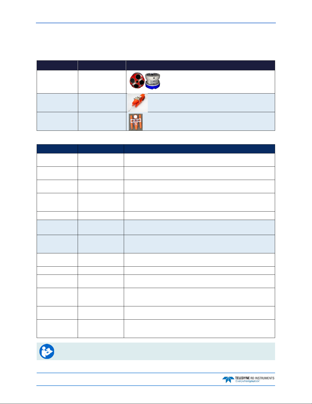
RiverPro/RioPro Inventory
Included with the RiverPro/RioPro system:
Part Number Name Description
RIVPRO1200-I
707-6025-02
71B-7007-xx RiverRay/RiverPro Boat
RiverPro 1200 kHz system
RioPro 1200 kHz system
(optional)
The RiverPro/RioPro system includes the transducer, dummy
plug, and protective cap. When unpacking, use care to prevent
physical damage to the transducer face and connector. Use a
soft pad to protect the transducer.
Tri-hull Boat and mounting plate for tethered deployments (shown
folded). Various GPS wiring optional configurations are available.
RIVERBOAT-xx RioPro Boat (optional) The RioPro requires the Riverboat for tethered deployments. Various GPS
wiring optional configurations are available.
Included with the RiverPro (RIVERPRO1200-A)/RioPro (RIOPRO-A) Accessories Kit:
Part Number Name Description
UK821 (RiverPro)
717-7000-00 (RioPro)
73B-6020-005
(RiverPro Only)
90B-8021-00 RiverPro/RioPro
907-8075-00 WinRiver II Software CD TRDI’s river and coastal data acquisition software package where the primary use is for
907-8040-00 RDI Tools Software CD Utility and testing software package including BBTalk that can be used to test the ADCP.
907-8080-00 SxS Pro Software CD
91B-8007-00
90B-8020-00 (CD)
95B-6127-00 Getting Started A printed reference card showing how to get started with the RiverPro/RioPro. A PDF
95B-6123-00 Deployment Guide A Printed guide showing the steps needs for a successful deployment.
957-6274-00 Serial Communications
957-6277-00 SD1000U Bluetooth
SD1000U
DAT5-G01R
N/A Spare parts and tools The RiverPro includes a driver and spare mounting hardware for the Boat mounting
Shipping case Shipping case with custom foam cutouts.
I/O cable The I/O cable is used for serial communications.
Documentation CD
(optional)
Q-View Software
(optional)
Setup Card
Communications Setup
Card
USB Bluetooth device
This CD has PDF versions of all of the RiverPro/RioPro documentation including the
RiverPro/RioPro ADCP Guide. Please read the manual!
discharge calculation. Although this is its primary function, it can be used for general
coastal survey applications.
cessing program. This CD will be included with the SxS Pro upgrade (registration code is
Q-View is designed for customers using WinRiver II software to have easy access to an
evaluation of the quality of collected data while they are still in the field and back in the
office. Once purchased, a download link and activation code is sent.
version is included on the RiverPro/RioPro documentation CD.
A printed quick reference card showing serial communications setup. A PDF version is
included on the WinRiver II CD.
A printed quick reference card showing Bluetooth communications setup using the
SD1000U. A PDF version is included on the WinRiver II CD.
USB Bluetooth device SD1000U and Sena DAT5-G01R antenna.
plate. The RiverPro and RioPro includes a 3mm Allen wrench for removing and connecting the I/O cable strain relief.
For instructions on using the USB Bluetooth device, see the WinRiver II or SxS Pro Software
User’s Guide and the instructions included with the device on the Bluetooth driver CD.
Page 2
EAR-Controlled Technology Subject to Restrictions Contained on the Cover Page.
RiverPro and RioPro ADCP Guide October 2017
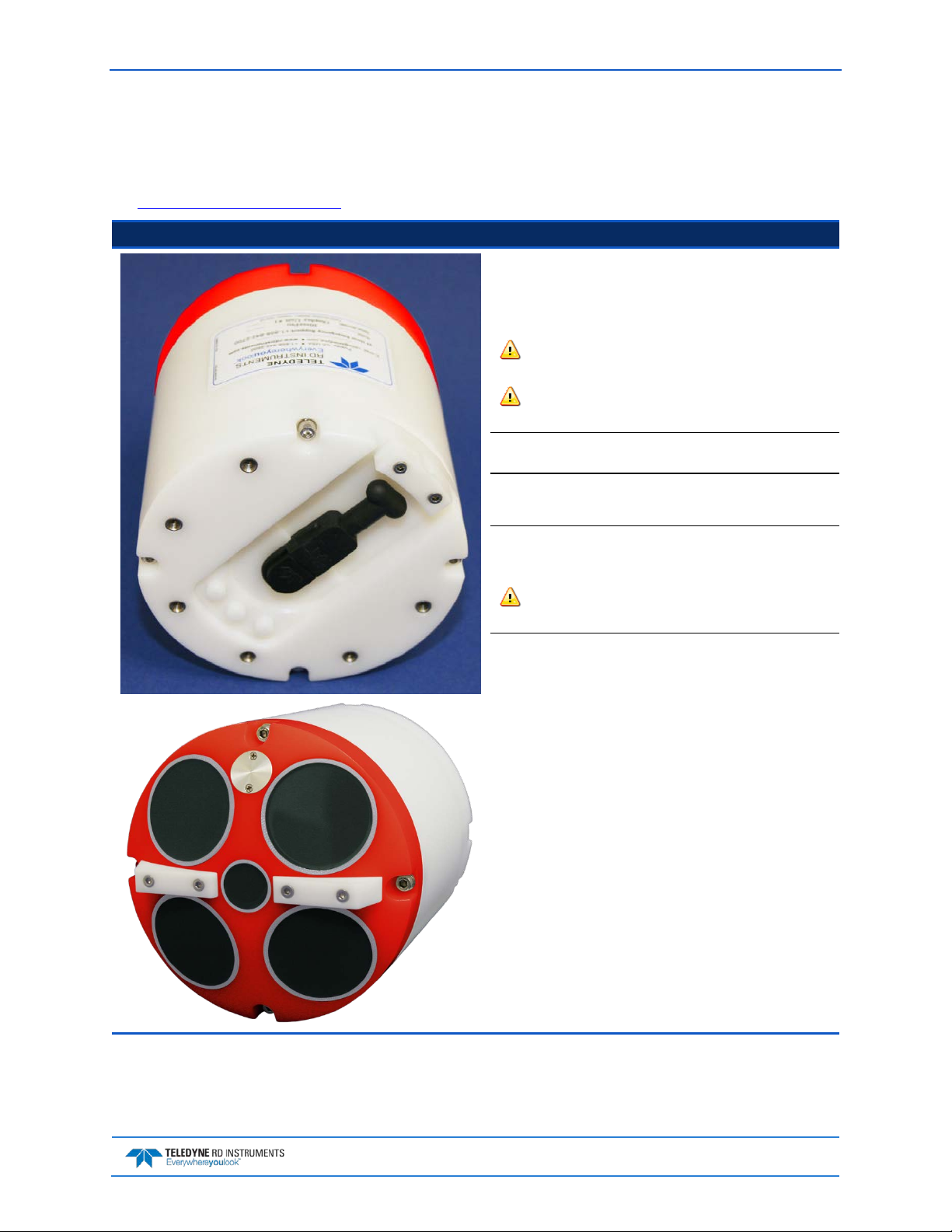
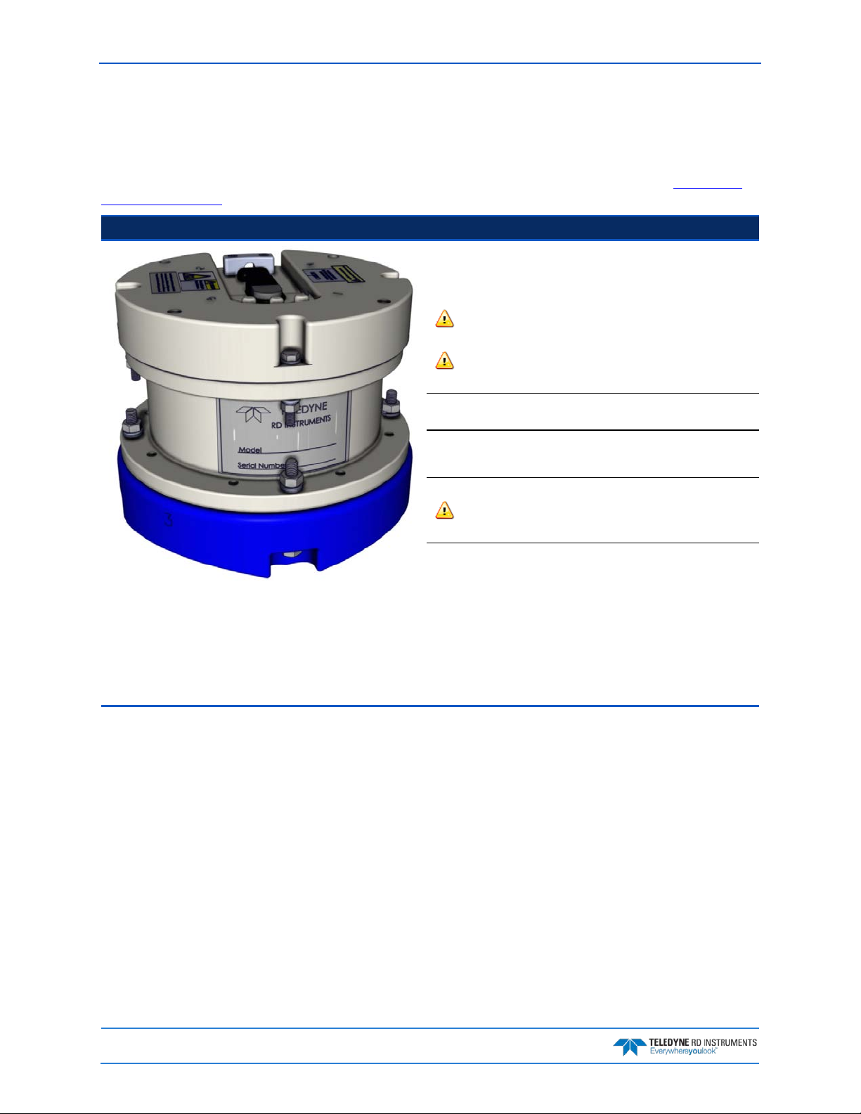
RiverPro Overview
The RiverPro transducer assembly contains the end-cap, housing, transducer ceramics, and electronics.
The standard acoustic frequencies are four 1200 kHz Janus beams and one 600 kHz vertical beam. See
the Outline Installation Drawings for dimensions and weights.
Picture Description
The Input/Output (I/O) cable connects the RiverPro ADCP to the
computer and external power supply. When the cable is not connected, use the dummy plug to protect the connector.
The LEDs on the end-cap indicates the status of the RiverPro system.
The I/O connector should not be exposed to extended peri-
ods of heat or direct sunlight.
Always apply lubricant before connecting the I/O cable to the
RiverPro.
The RiverPro is intended to be operated as a surface mounted
system only. No depth rating is provided.
The Thermistor measures the water temperature.
The black urethane faces covers the transducer ceramics.
The Vertical Beam allows for depth measurement directly under
the RiverPro.
Never set the transducer on a hard surface. The urethane
faces may be damaged.
The RiverPro electronics and transducer ceramics are mounted to
the transducer head. The numbers embossed on the end-cap and
transducer head indicate the beam number.
The RiverPro ADCP incorporates an internal GPS module intended
for GeoReference purposes. The RiverPro captures the GGA and
VTG NMEA strings from the internal GPS module and reports
them in the PD0 data stream using the general NMEA format.
WinRiver II provides status of this module and displays the data
during both data collection and playback.
EAR-Controlled Technology Subject to Restrictions Contained on the Cover Page.
Page 3
October 2017 RiverPro and RioPro ADCP Guide
RioPro Overview
The RioPro is an upgraded 1200 kHz WorkHorse Rio Grande system that contains an updated transducer
head, RiverPro electronics, and new end-cap. The system uses the original Rio Grande housing, shipping
case, and I/O cable. The standard acoustic frequency is four 1200 kHz Janus beams. See the Outline In-
stallation Drawings for dimensions and weights.
Picture Description
The Input/Output (I/O) cable connects the RioPro ADCP to the computer and external power supply. When the cable is not connected,
use the dummy plug to protect the connector.
The LEDs on the end-cap indicates the status of the RioPro system.
The I/O connector should not be exposed to extended periods of
heat or direct sunlight.
Always apply silicone lubricant before connecting the I/O cable
to the RioPro.
The RioPro is intended to be operated as a surface mounted system
only. No depth rating is provided.
The Thermistor measures the water temperature.
The orange urethane faces covers the transducer ceramics.
Never set the transducer on a hard surface. The urethane faces
may be damaged.
The RioPro electronics and transducer ceramics are mounted to the
transducer head. The numbers embossed on the end-cap and transducer head indicate the beam number.
The RioPro ADCP incorporates an internal GPS module intended for
GeoReference purposes. The RiverPro captures the GGA and VTG
NMEA strings from the internal GPS module and reports them in the
PD0 data stream using the general NMEA format. WinRiver II provides status of this module and displays the data during both data
collection and playback.
Page 4
EAR-Controlled Technology Subject to Restrictions Contained on the Cover Page.
RiverPro and RioPro ADCP Guide October 2017
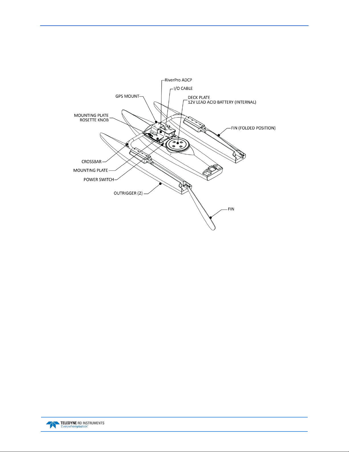
Boat Overview
The RiverRay/RiverPro/RioPro boat is designed to maintain the transducer at a constant depth in the water with minimal water flow disturbance.
Figure 1. RiverRay/RiverPro/RioPro Boat Overview
Computer Overview
TRDI designed the RiverPro/RioPro ADCP to use a Windows® compatible computer. The computer controls the RiverPro/RioPro and displays its data, usually through our WinRiver II or SxS Pro programs.
Minimum Computer Hardware Requirements:
• Windows 10®, Windows 8®, Windows 7® Desktop, Laptop, or Netbook computer
• Screen resolution above 1024x768
• One Serial Port (two or more High Speed UART Serial Port recommended)
• Bluetooth Interface or USB port
EAR-Controlled Technology Subject to Restrictions Contained on the Cover Page.
Page 5

October 2017 RiverPro and RioPro ADCP Guide
Power Overview
The RiverPro/RioPro ADCP requires a DC supply between 10.5 volts and 18 volts. Either an external DC
power supply or battery can provide this power. If using a battery, use the largest rated amp-hour battery
as possible. A car battery should last one to two days powering a 1200 kHz ADCP.
Check that the battery voltage is above 10.5 Volts DC. RiverPro/RioPro ADCPs will work at
10.5 VDC with at least 400 milli amps; however, batteries with voltages below 11 VDC are at
The power supply must be able to handle the inrush current as well. Inrush current is the current required
to fully charge up the capacitors when power is applied to the RiverPro/RioPro. The capacitors provide a
store of energy for use during transmit. The inrush current is as high as 3 Amps rms. The RiverPro/RioPro will draw this amperage until its capacitors are fully charged.
If the power supply limits the current or the power drop on the cable is significant, then the power on cycle will take longer. It can take up to one minute. If the power shuts down during the inrush current draw,
this may not allow the RiverPro/RioPro’s electronics to start.
or near their end of life, and are approaching uselessness.
Auto-Adaptive Water Profiling Mode
The RiverPro/RioPro uses an auto-adaptive water profiling mode which automatically adjusts velocity
profiling parameters every ensemble (reading) based on the water depth and other characteristics to
maintain a balance between velocity precision, spatial resolution, and data storage requirements. This approach allows consistent data quality throughout a transect and discharge measurement regardless of
changes in the water depth or flow characteristics without the need for user intervention.
For more details please refer to the chapter on Water Profiling Modes in the WinRiver II User
Guide.
RiverPro/RioPro Options
• Maintenance Kit – This kit (P/N 75BK6032-00 for RiverPro, 757K6037-00 for RioPro) contains a
complete set of O-Rings and close-up hardware (see Maintenance Kit).
• Manual Profile Modes – These modes allows the RiverPro/RioPro to override the automatic profil-
ing mode and adds additional water profiling commands (see Water Profiling Commands). To
purchase a feature upgrade, please contact sales.
• Q-View Software – Q-View is designed for customers using TRDI’s discharge measurement prod-
ucts such as the RiverRay, RiverPro/RioPro, StreamPro, and Rio Grande ADCPs with the Win-
River II software to have easy access to an evaluation of the quality of collected data while they
are still in the field and back in the office. To purchase a registration code to enable the software,
please contact sales.
• SxS Pro – The SxS Pro software can be used in place of the Wi n Ri v er II software. To purchase a
registration code to enable the software’s full capability, please contact field service.
SxS Pro software and manuals can be downloaded at http://www.teledynemarine.com/rdi
Page 6
EAR-Controlled Technology Subject to Restrictions Contained on the Cover Page.
RiverPro and RioPro ADCP Guide October 2017
• GPS wiring and mounting kits – GPS wiring and mounting kits for the RiverPro/RioPro boat are
available for a variety of GPS systems. GPS wiring and mounting kits are normally ordered in conjunction with new RiverPro/RioPro systems and any required boat modifications are performed
at the factory. Common GPS wiring/mounting kits are shown below; additional kits and custom
configurations are available – consult TRDI for more information.
Part Number Supported GPS Systems Notes
GWIR-HA100
GWIR-HS321 Hemisphere S321
GWIR-KTA various
Hemisphere A101, A325, and
AtlasLink
Integrated antenna/receiver. Includes internal cable, external cable, and
GPS mount. GPS powered from battery in boat.
Includes internal cable, external cable, and GPS mount. Powered by internal
battery in GPS.
Includes (2) bulkhead connectors with attached internal cables only. GPS
mount and additional required interconnect cables sold separately.
• Hemisphere A101 DGPS kit –Hemisphere A101 Smart Antenna DGPS & configuration cable.
• Hemisphere Atlaslink DGPS kits – Atlas capable Hemisphere Atlaslink Smart Antenna DGPS with
configuration cable. L1/L2, GLONASS, and RTK support optionally available.
• Hemisphere S321 DGPS kits – Atlas capable Hemisphere S321 Smart Antenna DGPS with configu-
ration cable, integrated batteries, and integrated radio/cellular modem. L1/L2, GLONASS, and
RTK support optionally available.
GPS manuals and software are available for download:
http://www.hemispheregps.com/Support/PrecisionProductSupport/Antennas/
TechnicalDocumentation/tabid/553/Default.aspx
• High Speed Riverboat – For discharge measurements in applications with high water velocities or
challenging surface turbulence conditions where the standard boat does not provide stable operation. Can be used with RiverPro/RioPro, RiverRay, and Rio Grande ADCPs.
• Depth Sounder – General purpose/non survey grade depth sounder for measuring depth directly
under the RiverPro/RioPro or for redundancy with the bottom track depth measurement.
• Carrying Cases – Soft-sided and hard-sided carrying cases for the RiverPro/RioPro boat are availa-
ble. Contact TRDI for more information.
EAR-Controlled Technology Subject to Restrictions Contained on the Cover Page.
Page 7
October 2017 RiverPro and RioPro ADCP Guide
Setting up the RiverPro/RioPro System
Use this section to connect the RiverPro/RioPro to a computer and establish communications. Install the
RDI Tools software in order to communicate with the RiverPro/RioPro. For collecting data, install the
WinRiver II, SxS Pro (optional), and Q-View (optional) software.
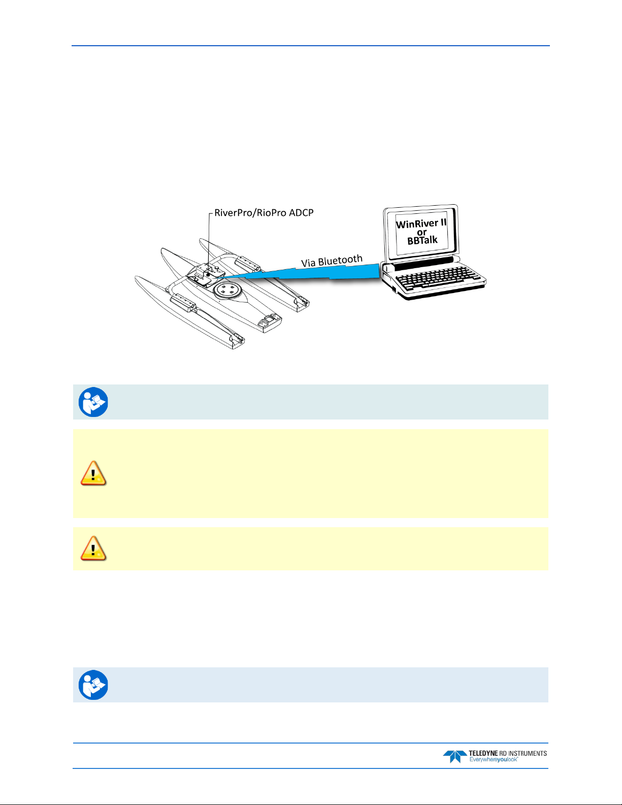
Bluetooth Connection
Use these next steps to setup a Bluetooth connection to the RiverPro/RioPro.
Figure 2. RiverPro/RioPro Connections – Bluetooth Connection
For instruction on using the SD1000U USB Bluetooth device, see the WinRiver II or SxS Pro
Software User’s Guide and the instructions and Bluetooth CD included with the device.
Some Bluetooth devices may ask for a passkey, PIN code, Pair code, Pairing code, Security
code, or Bluetooth code.
In all cases, the code is 0 or 0000 (zero, not the letter o).
To connect to a RiverPro/RioPro ADCP using the Bluetooth port:
1. Attach the boat’s cable to the ADCP’s connector and install the battery in the boat. Turn on the
boat power switch. Verify that both the red and green LEDs light. After a few seconds the red LED
should go out and the green LED will blink twice and then stay on. This indicates that the
RiverPro/RioPro self-test has passed.
The pin code is 0 for systems shipped prior to August 2017 and 0000 for systems shipped
after August 2017. If your system is sent in for repair and the Bluetooth module is replaced,
the pin code (if needed) will change from 0 to 0000.
For RiverPro/RioPro systems shipped after August 2017, the Microsoft® Bluetooth drivers
work with WinRiver II. For best results, use the USB Bluetooth device with the driver supplied
with the ADCP for WinRiver II.
2. Plug in the SD1000U device to a USB port and determine the Com port used.
See the WinRiver II SD1000U Bluetooth Communication Setup Card for instructions.
Page 8
EAR-Controlled Technology Subject to Restrictions Contained on the Cover Page.
RiverPro and RioPro ADCP Guide October 2017
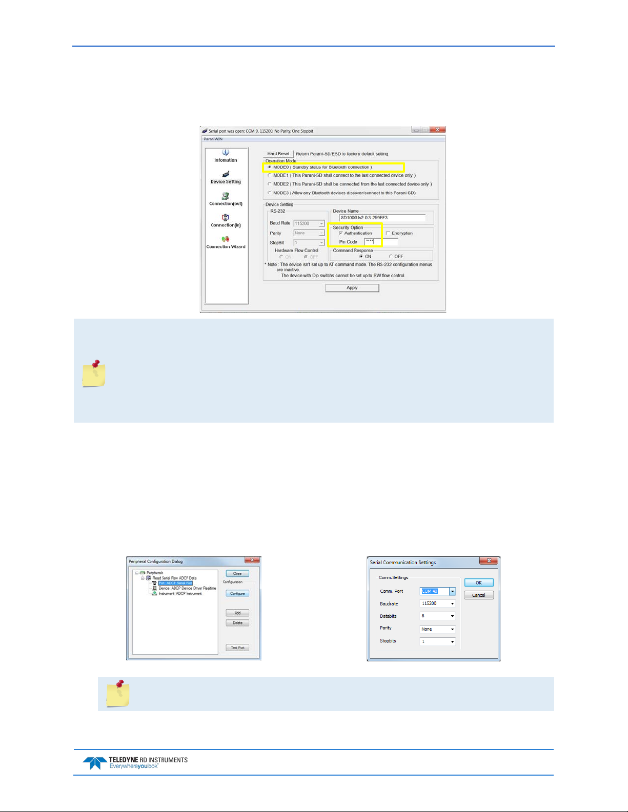
3. Run the ParaniWin program and connect to the ADCP. With the Bluetooth modules used since
August 2017 (or a repaired older unit where the Bluetooth module was replaced) select Mode 0
and you may or may not need to select Authentication (not Encryption). The Pin Code is 0000
(four zeros) and click Apply.
You may need to use either Authentication or no authentication when using ParaniWin with
an SD100U. Try one, and if does not work try the other. Use whichever one works going
forward.
The selection of Mode 0 or Mode 1 is independent of Authentication/no Authentication:
• Mode 1 automatically reconnects to the ADCP, but is otherwise identical to Mode 0.
• You must establish an outgoing connection before you can switch to Mode 1, but once in
Mode 1 you can connect to a different ADCP without switching back to Mode 0.
4. Exit the ParaniWin program.
5. Start WinRiver II.
6. On the Configure menu, select Peripherals.
7. Select Port: ADCP Serial Port and then click the Configure button.
8. Select the Comm. Port number as noted in step 2. The Baudrate must be set to 115200. Leave
the Databits, Parity, and Stopbits as shown.
9. Click OK to close the Serial Communication Settings screen.
Note it may take several seconds to accept the Comm. Port selection.
In this example, the Comm. Port is set to Com Port 40.
EAR-Controlled Technology Subject to Restrictions Contained on the Cover Page.
Page 9
October 2017 RiverPro and RioPro ADCP Guide
10. Click the Test Port button. The RiverPro/RioPro banner appears.
>break
RiverPro/RioPro
Teledyne RD Instruments (c) 2015
All rights reserved.
Firmware Version: 56.xx
>
11. Click the Close button to exit the Test Port Dialog.
12. Click the Close button once more to exit the Peripherals Configuration Dialog.
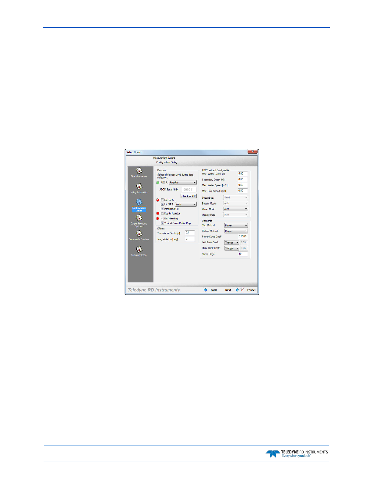
13. Start a new measurement in WinRiver II.
14. On the Configuration D i alo g, ensure the ADCP type matches the RiverPro/RioPro and the
indicator next to the RiverPro/RioPro is green. Verify the blue LED on the RiverPro/RioPro
ADCP is on.
Page 10
EAR-Controlled Technology Subject to Restrictions Contained on the Cover Page.
RiverPro and RioPro ADCP Guide October 2017
Serial Connection
To set up the RiverPro/RioPro ADCP:
1. The I/O cable connector must be lubricated before connecting. Connect the I/O cable to the
RiverPro/RioPro ADCP.
Always apply silicone lubricant before connecting the I/O cable. See I/O Cable and Dummy
Plug and I/O Cable Connector Lubricant for details.
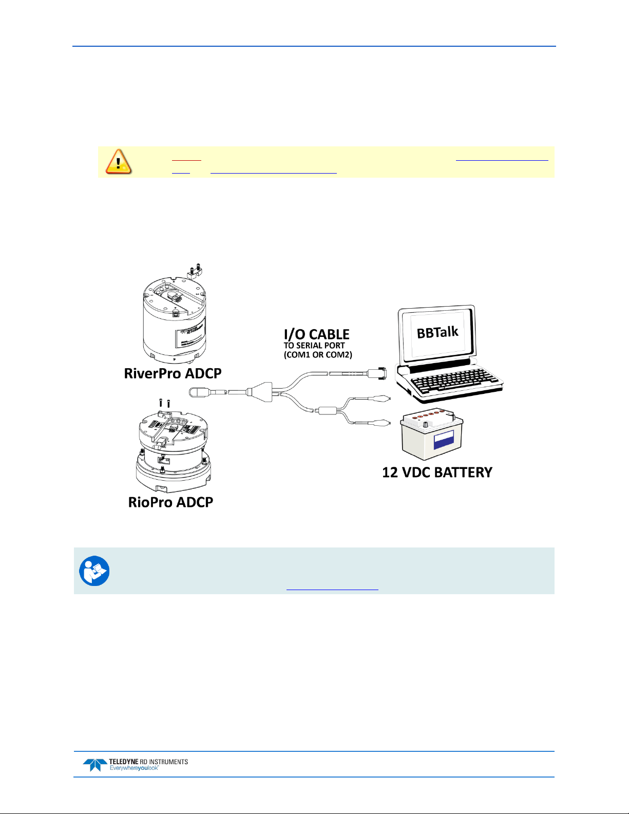
2. Attach the I/O cable to the computer’s communication port. The standard communications settings are RS-232, 115200-baud, no parity, 8 data bits and 1 stop bit.
3. Connect a battery or DC power supply to the power connectors. Verify that both the red and green
LEDs light. After a few seconds the red LED should go out and the green LED will blink twice and
then stay on. This indicates that the RiverPro/RioPro self-test has passed.
Figure 3. RiverPro/RioPro Serial Connection
For information on how to set up communications with WinRiver II, see the WinRiver II Serial
Communications Setup Card or see Chapter 2 in the WinRiver II Software User's Guide.
For Bluetooth connection, see Bluetooth Connection.
EAR-Controlled Technology Subject to Restrictions Contained on the Cover Page.
Page 11
October 2017 RiverPro and RioPro ADCP Guide
Connecting to the RiverPro/RioPro
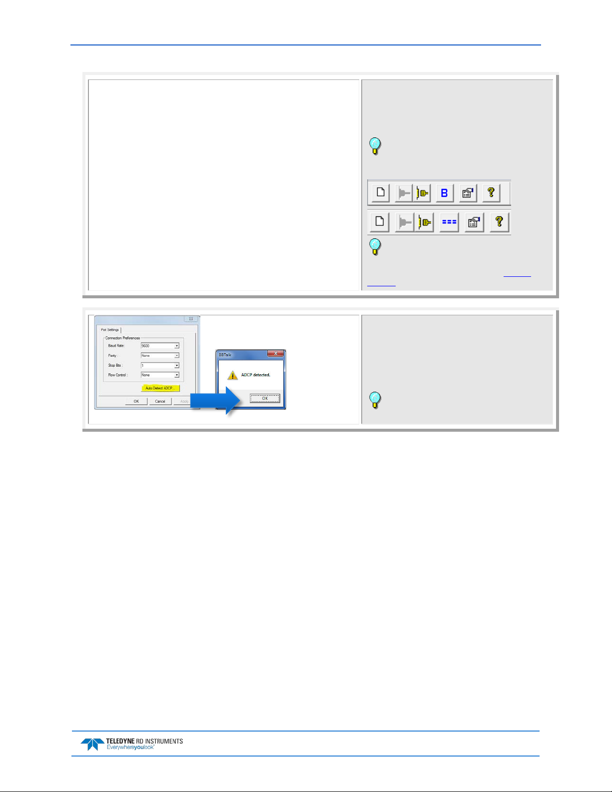
To connect to the RiverPro/RioPro ADCP using the BBTalk software:
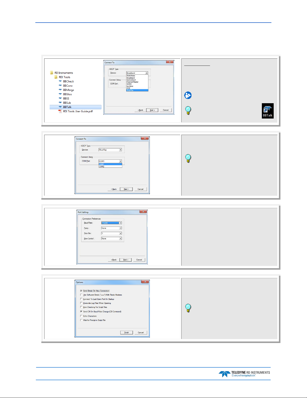
Start BBTalk
Start the BBTalk program by clicking Start, All Programs, RD Instruments, RDI Tools, BBTalk.
On the Connect To screen, select RiverRay.
For help on using BBTalk, see the RDI Tools User’s
Guide.
Use the BBTalk desktop icon to start
BBTalk.
Select the COM port the RiverPro/RioPro ADCP cable is
connected to.
Click Next.
BBTalk can be used with Bluetooth communica-
tions. Right-click on the RDI RPro icon in the Bluetooth
management software and make sure that that it is
connected and verify what COM Port is used.
Enter the Baud Rate, Parity, Stop Bits, and Flow Con-
trol. If you are unsure of the settings, leave them at
the default settings as shown.
Click Next.
Page 12
Check Send Break On New Connection and Send CK
on Baud Rate Change (CB Command).
Click Finish.
If a Bluetooth connection is used, check the Use
Software Break (“===”) With Radio Modems box.
EAR-Controlled Technology Subject to Restrictions Contained on the Cover Page.
RiverPro and RioPro ADCP Guide October 2017
RioPro Banner
RioPro
Teledyne RD Instruments (c) 2015
All rights reserved.
Firmware Version: 56.03
>
RiverPro Banner
RiverPro
Teledyne RD Instruments (c) 2015
All rights reserved.
Firmware Version: 56.03
>
On the File menu, click Send A Break. Pressing the End
key will also send a break or press the === button or B
on the Toolbar.
The banner message should appear on the log file window.
The BBTalk toolbar will display === if it is config-
ured for using Software Breaks or B if it is configured
to send a Hard Break.
If the RiverPro/RioPro ADCP does not respond,
check the serial port, cables, DC power supply or battery connection. If necessary, refer to the Trouble-
shooting section.
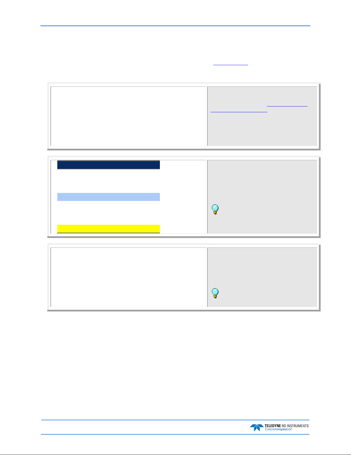
If the banner is not readable or visible:
On the File menu, click Properties.
Click the Auto Detect ADCP button.
Click OK when the RiverPro/RioPro is detected. Try to
wake up the RiverPro/RioPro again.
Both BBTalk and the RiverPro/RioPro must use
the same Baud rate.
EAR-Controlled Technology Subject to Restrictions Contained on the Cover Page.
Page 13
October 2017 RiverPro and RioPro ADCP Guide
RiverPro
>cb?
Changing the Baud Rate in the ADCPs
The RiverPro/RioPro can be set to communicate at baud rates from 1200 to 115200. The factory default
baud rate is always 115200 baud. The baud rate is controlled via the CB-command. The following procedure explains how to set the baud rate and save it in the RiverPro/RioPro. This procedure assumes using
the program BBTalk that is supplied by Teledyne RD Instruments.
Teledyne RD Instruments (c) 2015
All rights reserved.
Firmware Version: 56.xx
>
>cr1
[Parameters set to FACTORY defaults]
BAUD RATE CB-command
1200 CB111
2400 CB211
4800 CB311
9600 CB411
19200 CB511
38400 CB611
57600 CB711
115200 CB811 (Default)
CB = 411 ----------------- Serial Port Control (Baud
[4=9600]; Par; Stop)
>cb811
>CK
[Parameters saved as USER defaults]
>cb?
CB = 811 ----------------- Serial Port Control (Baud
[8=115200]; Par; Stop)
>
Connect the RiverPro/RioPro to the computer and apply power.
Start the BBTalk program and establish communica-
tions with the RiverPro/RioPro.
Wake up the RiverPro/RioPro by sending a break signal
with the End key.
At the ">" prompt in the communication window, type
CR1 then press the Enter key. This will set the
RiverPro/RioPro to the factory default settings.
Send the CB-command that selects the baud rate you
wish. The table on the left shows the CB-command settings for different baud rates with no parity and 1 stop
bit.
For example, to change the baud rate to 115200, at
the ">" prompt in the communication window, type
cb811 then press the Enter key.
The CB? command will identify the communication setting.
BBTalk will send the command CK to save the new
baud rate setting.
Exit BBTalk.
The RiverPro/RioPro is now set for the new baud rate.
The baud rate will stay at this setting until changed
again with the CB command.
Exit BBTalk so the communication port is available for use with other programs.
Page 14
EAR-Controlled Technology Subject to Restrictions Contained on the Cover Page.
RiverPro and RioPro ADCP Guide October 2017
RiverPro/RioPro Recorder
The recorder contains approximately 16 megabytes of solid-state nonvolatile memory, which can be used
to record data. If more data is collected than fits in the memory, the newest data will not be recorded.
Once the recorder fills up, the recorder MUST be erased before re-deploying the RiverPro/RioPro (start
pinging again).
If the RiverPro/RioPro is set to record data (MR1) and the recorder is full, the RiverPro/RioPro
will not start pinging and will return a RECORDER NOT READY message.
Use BBTalk version 3.08 or greater. Older versions of BBTalk do not have the RiverRay device.
See the RDI Tools User’s Guide for details on using BBTalk.
Enabling the Loop Recorder
The loop recorder is off by default.
To enable the loop recorder:
1. Start BBTalk. Configure BBTalk to connect to a RiverPro/RioPro ADCP type device.
2. Send the MR1 command to enable the recorder.
Using the loop recorder will slow down the RiverPro/RioPro’s ping rate.
3. When done recording data, send the MR0 command to turn the loop recorder off.
Recovering Data from the Loop Recorder
To recover data:
1. Start BBTalk. Configure BBTalk to connect to a RiverRay ADCP type device (see Connecting to
the RiverPro/RioPro).
Make sure to select RiverRay as the Device. BBTalk will communicate with the
RiverPro/RioPro if Workhorse or another ADCP type is selected as the device, but will not be
able to recover the recorder.
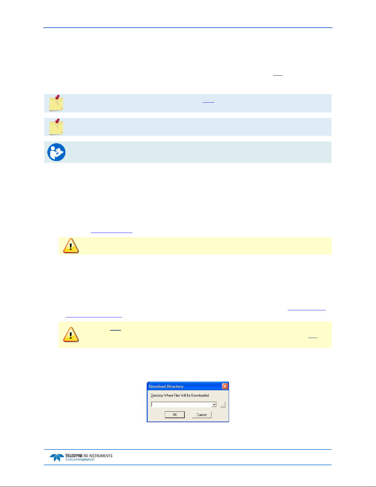
2. On the File menu, click Recover Loop Recorder.
3. Enter the directory where the files will be downloaded. Click the “…” button to browse for the di-
rectory. Click OK.
Figure 4. Download Directory
EAR-Controlled Technology Subject to Restrictions Contained on the Cover Page.
Page 15
October 2017 RiverPro and RioPro ADCP Guide
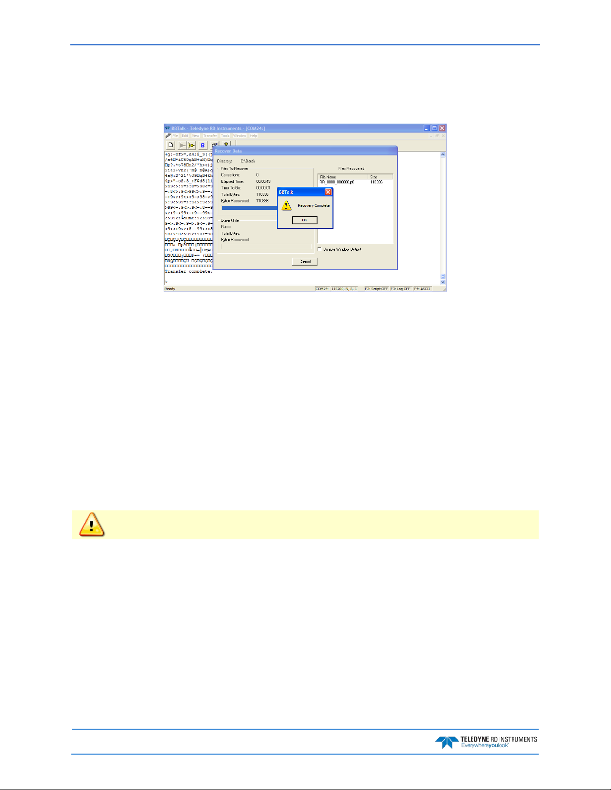
4. BBTalk displays current protocol status, filename being received, total size of receiving file and
current number of bytes received (see Figure 5, page 16).
5. When recovery is complete, click OK.
Figure 5. Recover Loop Recorder
Erasing Data from the Loop Recorder
To erase data:
1. Start BBTalk. Configure BBTalk to connect to a RiverRay ADCP type device.
2. At the “>” prompt, type ME ErAsE. To make it more difficult to accidentally erase the data, the
word “erase” must be typed with exactly one space after the “ME” (which is not case sensitive) and
with alternating upper and lower case letters, as shown.
3. Erasing the loop-recorder will take several minutes, and no status updates are provided during
the erase process. When complete, the status will be displayed on screen as shown below.
>me ErAsE
Erasing recorder (may take a few minutes)...
Erasing recorder (may take a few minutes)... Recorder erased.
Erasing recorder (may take a few minutes)... ERR: Can’t erase recorder.
>
Once erased, data is not recoverable.
4. When erasing is complete, exit BBTalk.
Page 16
EAR-Controlled Technology Subject to Restrictions Contained on the Cover Page.

RiverPro and RioPro ADCP Guide October 2017
Caring for the RiverPro/RioPro System
This section contains a list of items to be aware of every time the RiverPro/RioPro is handled, used, or deployed. Please refer to this list often.
General Handling Guidelines
• Never set the transducer on a hard or rough surface. The urethane faces may be damaged.
• Use light amounts of silicone lubricant (such as 3M
4678-4930-3) on both the male pins and female socket to help seat the cable connectors. Wipe off
excessive silicone spray from the metal portions of the pins. Regular lubrication is required: Apply
dry type silicone lubricant prior to each connection.
• Disconnect the I/ O cable by pulling it straight away from the connector. Do not apply any upward
or angular force on the end-cap connector as the I/O cable is being disconnected. Stressing the
connector may cause the RiverPro/RioPro to flood.
• Do not over-tighten the locking sleeve on the I/O cable. The threads can strip.
• Do not expose the transducer faces to prolonged sunlight. The urethane faces may develop cracks.
Cover the transducer faces on the RiverPro/RioPro if it will be exposed to sunlight.
TM
Silicone Lubricant (Dry Type) ID No: 62-
• The I/O connector should not be exposed to extended periods of heat or direct sunlight. The plastic
may become brittle. Cover the connector on the RiverPro/RioPro if it will be exposed to sunlight.
• Do not store the RiverPro/RioPro in temperatures over 60 degrees C. The urethane faces may be
damaged.
• Do not scratch or damage the O-ring surfaces or grooves. If scratches or damage exists, they may
provide a leakage path and cause the RiverPro/RioPro to flood. Do not risk a deployment with dam-
aged O-ring surfaces.
• Do not lift or support a RiverPro/RioPro by the external I/O cable. The connector or cable will
break.
Assembly Guidelines
• Read the Maintenance section for details on RiverPro/RioPro re-assembly. Make sure the housing
assembly O-ring stays in the groove when re-assembling the RiverPro/RioPro. Tighten the hardware as specified. Loose, missing, stripped hardware, or a damaged O-ring can cause the RiverPro/Ri-
oPro transducer to flood.
• The RiverPro/RioPro I/O cable may be connected while slightly wet; do not connect under water.
Deployment Guidelines
• Read the WinRiver II Software User’s Guide or SxS Pro Software User’s Guide. These guides in-
clude tutorials on how to collect data.
• A compass calibration should be conducted at every new measurement location, and whenever
the RiverPro/RioPro mounting or adjacent ancillary equipment is changed 0r repositioned. A
properly calibrated compass is essential for conducting the Loop Moving Bed test, and for using GPS
data as the navigation reference.
• Avoid using ferro-magnetic materials in the mounting fixtures or near the RiverPro/RioPro.
Ferro-magnetic materials affect the compass.
EAR-Controlled Technology Subject to Restrictions Contained on the Cover Page.
Page 17

October 2017 RiverPro and RioPro ADCP Guide
NOTES
Page 18
EAR-Controlled Technology Subject to Restrictions Contained on the Cover Page.
 Loading...