

Page 1
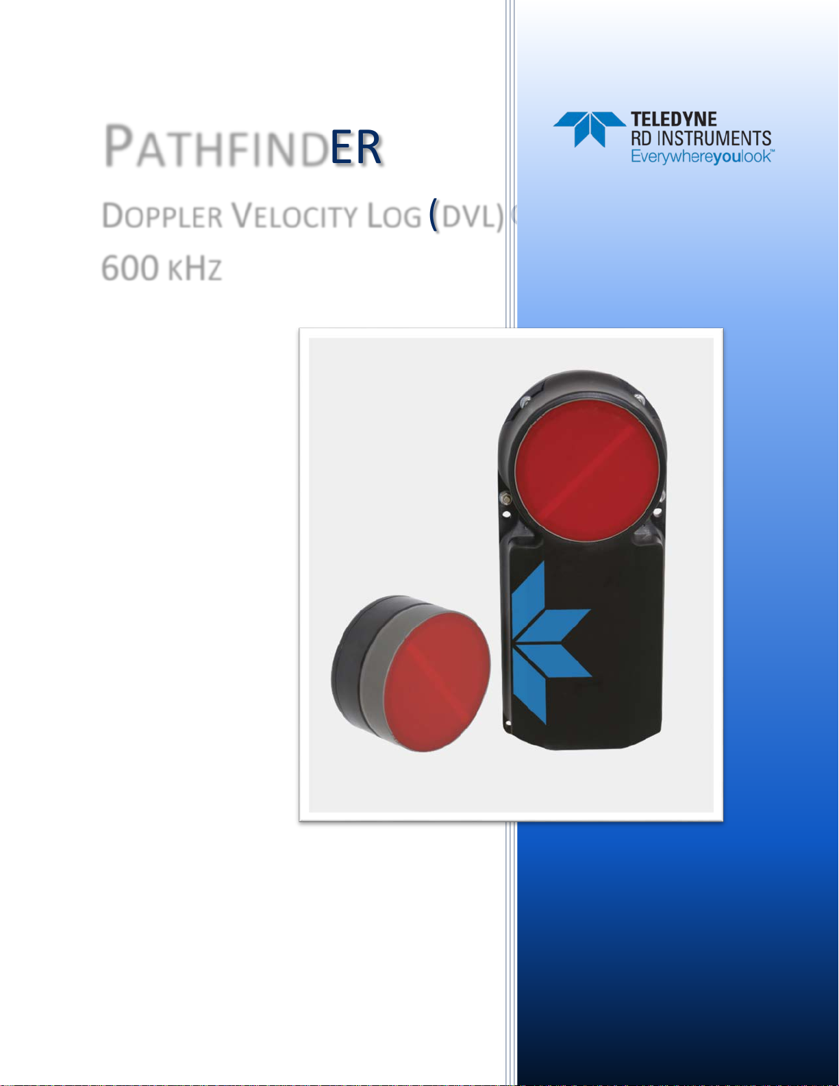
PATHFINDER
DOPPLER VELOCITY LOG (DVL) GUIDE
600 KHZ
Information included herein is controlled by the Export Administration Regulations
(EAR) and may require an export license, license exception or other approval from the
appropriate U.S. Government agency before being exported from the United States or
provided to any foreign person. Diversion contrary to U.S. law is prohibited.
P/N 95B-6116-00 (April 2018)
© 2018 Teledyne RD Instruments, Inc. All rights reserved.
Page 2

Page ii
EAR-Controlled Technology Subject to Restrictions Contained on the Cover Page.
Page 3

TABLE OF CONTENTS
CHAPTER 1 - AT A GLANCE ...................................................................................................................................1
Overview ...................................................................................................................................................... 2
Pathfinder Options ....................................................................................................................................... 4
Inventory ...................................................................................................................................................... 5
Optional Kits ......................................................................................................................................... 6
Health & Environment Monitoring Sensors ................................................................................................. 8
Setting up the Pathfinder System ................................................................................................................ 9
Computer and Software Considerations .............................................................................................. 9
Software Installation ............................................................................................................................ 9
Power Overview ................................................................................................................................... 10
Cables and Connector Protective Cap .................................................................................................. 10
Setting Up the Pathfinder ROV System ................................................................................................ 12
Setting Up the Pathfinder OEM System ............................................................................................... 13
Cable Wiring Diagrams ......................................................................................................................... 15
Connecting to the Pathfinder ....................................................................................................................... 17
Using the Network Configuration Page ................................................................................................ 18
Using the Ethernet Communications ................................................................................................... 19
Using TCP Protocol ......................................................................................................................... 19
Using UDP Protocol ........................................................................................................................ 20
Ethernet Module Firmware Update ..................................................................................................... 22
Testing the Pathfinder System ..................................................................................................................... 23
Caring for the Pathfinder System ................................................................................................................. 24
General Handling Guidelines ................................................................................................................ 24
Installation Guidelines .......................................................................................................................... 24
CHAPTER 2 – SYSTEM INT EGRATION .......................................................................................................................25
System Integration Introduction .................................................................................................................. 26
DVL Theory ................................................................................................................................................... 26
BroadBand Doppler .............................................................................................................................. 26
Bottom Tracking ................................................................................................................................... 26
Water Tracking ..................................................................................................................................... 27
Required Conditions for Water Tracking ....................................................................................... 27
Water Tracking Parameters ........................................................................................................... 28
Current Profiling ................................................................................................................................... 28
Beam Coordinate Systems ................................................................................................................... 29
DVL Performance and Influencing Factors ........................................................................................... 31
Long Term Performance ................................................................................................................ 31
Bottom Track ................................................................................................................................. 31
Water Track ................................................................................................................................... 31
Short Term Performance ...................................................................................................................... 32
Bottom Track ................................................................................................................................. 32
Water Track ................................................................................................................................... 32
Altitude Performance ........................................................................................................................... 33
Bottom Type & Slope ..................................................................................................................... 33
Temperature & Salinity .................................................................................................................. 33
Pitch & Roll..................................................................................................................................... 34
Transmit Power .............................................................................................................................. 34
Slant Range Performance ..................................................................................................................... 34
Speed of Sound Variation .............................................................................................................. 34
Bottom Slope ................................................................................................................................. 35
Pitch & Roll..................................................................................................................................... 35
Resolution ...................................................................................................................................... 35
Mechanical Integration Considerations ....................................................................................................... 36
Alignment ............................................................................................................................................. 36
Page iii
EAR-Controlled Technology Subject to Restrictions Contained on the Cover Page.
Page 4

Beam Clearance ................................................................................................................................... 37
Mounting the Instrument ..................................................................................................................... 37
Pitch & Roll ........................................................................................................................................... 37
Routing Cables...................................................................................................................................... 38
Electrical Integration Considerations ........................................................................................................... 39
Grounding Issues .................................................................................................................................. 39
Electrical and Grounding Testing Best Practices .................................................................................. 40
Electro-Magnetic Interference (EMI) ................................................................................................... 41
EMI Coupling Through Cables .............................................................................................................. 41
Power Consumption ............................................................................................................................. 42
Inrush Currents..................................................................................................................................... 42
Acoustic Integration Considerations ............................................................................................................ 43
Flow Noise ............................................................................................................................................ 43
Cavitation ............................................................................................................................................. 43
Ringing.................................................................................................................................................. 43
Mounting Considerations ..................................................................................................................... 44
Windows Use Considerations ............................................................................................................... 44
Recommended Practices for Window Use ..................................................................................... 45
SONAR Interference Considerations .................................................................................................... 46
Interference Detection and Mitigation ................................................................................................ 46
Reference, Data & Timing Considerations ................................................................................................... 47
Coordinate Frames ............................................................................................................................... 47
Data Screening ..................................................................................................................................... 47
Three-Beam Solution............................................................................................................................ 48
Ping Timing ........................................................................................................................................... 48
System Synchronization ....................................................................................................................... 49
Operational and Setup Considerations ........................................................................................................ 49
Unfavorable Environments .................................................................................................................. 49
Triggering ............................................................................................................................................. 50
Design Considerations & Bench Test .................................................................................................... 50
Troubleshooting ........................................................................................................................................... 51
Communications Issues ........................................................................................................................ 51
Initial Shakedown Deployment .................................................................................................................... 51
Troubleshooting Checklist .................................................................................................................... 51
Identify Unit ................................................................................................................................... 51
Run Built-In Tests ........................................................................................................................... 51
Provide Unit Setup ......................................................................................................................... 52
Describe Deployment Environment & Operational Conditions ..................................................... 53
Describe the System Installation .................................................................................................... 53
Provide Raw Data & Describe Issue for Analysis by TRDI ............................................................... 53
Provide Additional Data for Analysis by TRDI ................................................................................ 53
Record Engineering Data for Analysis by TRDI ............................................................................... 53
Identifying EMI ............................................................................................................................................. 55
Purpose ................................................................................................................................................ 55
Adjustments ......................................................................................................................................... 55
Operation ............................................................................................................................................. 55
Install the NGSPFFT Software ........................................................................................................ 56
Connecting to the Pathfinder DVL ................................................................................................. 56
Check the Adjustments .................................................................................................................. 57
Zoom .............................................................................................................................................. 57
Mouse-Over: .................................................................................................................................. 57
Examples of Clean FFT Plots, No Interference ...................................................................................... 57
Examples of Interference ..................................................................................................................... 58
Alternative FFT Tool for Virtual Comports ........................................................................................... 60
Matlab Output Variable Definitions ............................................................................................................. 61
CHAPTER 3 – COLLECTING DATA ............................................................................................................................63
Pathfinder General Deployment Flow .......................................................................................................... 64
Page iv
EAR-Controlled Technology Subject to Restrictions Contained on the Cover Page.
Page 5

Creating or Modifying Command Files ......................................................................................................... 65
Sending Commands to the Pathfinder ......................................................................................................... 69
CHAPTER 4 - MAINTENANCE .................................................................................................................................71
Replaceable Parts ......................................................................................................................................... 72
Inspection Schedule ..................................................................................................................................... 74
Periodic Maintenance Items ........................................................................................................................ 75
Cleaning the Cable Connectors ............................................................................................................ 75
Transducer Inspection .......................................................................................................................... 76
Removing Biofouling ............................................................................................................................ 76
Zinc Anode Inspection and Replacement ............................................................................................. 77
Zinc Anode Inspection .................................................................................................................... 77
Zinc Anode Electrical Continuity Check .......................................................................................... 77
Zinc Anode Replacement ............................................................................................................... 77
Protective Coating Inspection .............................................................................................................. 79
Long Term Maintenance Items .................................................................................................................... 79
Updating the DVL Firmware ................................................................................................................. 79
CHAPTER 5 - RETURNING SYSTEMS TO TRDI FOR SERVICE ............................................................................................81
Shipping the Pathfinder ............................................................................................................................... 82
Returning Systems to the TRDI Factory ........................................................................................................ 83
Returning Systems to TRDI Europe Factory .................................................................................................. 84
CHAPTER 6 - SPECIFIC ATIONS ................................................................................................................................87
Operational Specifications ........................................................................................................................... 89
Environmental Specifications ....................................................................................................................... 90
Electrical Specifications ................................................................................................................................ 90
Communications Specifications ................................................................................................................... 90
Outline Installation Drawings ....................................................................................................................... 90
CHAPTER 7 - COMMANDS ....................................................................................................................................93
Data Communication and Command Format .............................................................................................. 94
Command Input Processing ................................................................................................................. 94
Data Output Processing........................................................................................................................ 95
Command Summary ..................................................................................................................................... 95
Command Descriptions ................................................................................................................................ 98
? – Help Menus .............................................................................................................................. 98
Break .............................................................................................................................................. 99
OL – Display Feature List ................................................................................................................ 99
Y – Display Banner ......................................................................................................................... 100
Bottom Track Commands ............................................................................................................................. 101
Available Bottom Track Commands ..................................................................................................... 101
BP – Bottom-Track Pings per Ensemble ......................................................................................... 101
BX – Maximum Tracking Depth ...................................................................................................... 102
Expert Bottom Track Commands ......................................................................................................... 103
#B1 - Blank Range with Bad Velocity.............................................................................................. 103
#B2 - Depth Memory Timeout ....................................................................................................... 104
#BA - Evaluation Amplitude Minimum ........................................................................................... 104
#BB – Bottom Blanking Interval ..................................................................................................... 104
#BC - Correlation Magnitude Minimum ......................................................................................... 105
#BE - Error Velocity Maximum ....................................................................................................... 105
#BF - Depth Guess .......................................................................................................................... 105
#BH – Gain Switch Threshold ......................................................................................................... 106
#BI - Gain Switch Altitude .............................................................................................................. 106
#BJ – Data Type Output Control..................................................................................................... 107
#BK - Water-Mass Layer Mode ...................................................................................................... 107
#BL - Water-Mass Layer Parameters .............................................................................................. 108
#BM – Bottom Mode ..................................................................................................................... 109
#BN - Speed Log Hold/Drop Control .............................................................................................. 109
Page v
EAR-Controlled Technology Subject to Restrictions Contained on the Cover Page.
Page 6

#BO - Distance Measure Filter Constant ........................................................................................ 110
#BQ – Over Range Limit ................................................................................................................. 110
#BS - Clear Distance Traveled ........................................................................................................ 110
#BY – Transmit Length ................................................................................................................... 111
#BZ – Low Altitude Mode ............................................................................................................... 111
Control System Commands .......................................................................................................................... 112
Available Control System Commands .................................................................................................. 112
CB - Serial Port Control .................................................................................................................. 112
CE – Enable Ethernet...................................................................................................................... 113
CF - Flow Control ............................................................................................................................ 113
CK - Keep Parameters .................................................................................................................... 114
CR – Retrieve Parameters .............................................................................................................. 114
CS – Start Pinging (Go) ................................................................................................................... 115
CT - Turnkey Operation .................................................................................................................. 115
CX – Input Trigger Enable ............................................................................................................... 116
CZ – Power Down ADCP ................................................................................................................. 117
Expert Control System Commands ....................................................................................................... 117
Environmental Commands ........................................................................................................................... 118
Available Environmental Commands ................................................................................................... 118
EA - Heading Alignment ................................................................................................................. 118
EC - Speed of Sound ....................................................................................................................... 119
ED - Depth of Transducer ............................................................................................................... 119
EH - Heading .................................................................................................................................. 120
EP - Pitch and Roll Angles ............................................................................................................... 120
ER - Roll Angle ................................................................................................................................ 121
ES – Salinity .................................................................................................................................... 122
ET - Temperature ........................................................................................................................... 122
EU - Up/Down Orientation ............................................................................................................. 123
EV - Heading Bias ........................................................................................................................... 123
EX – Coordinate Transformation .................................................................................................... 124
EZ - Sensor Source .......................................................................................................................... 125
Expert Environmental Commands ........................................................................................................ 126
#EE - Environmental Data Output .................................................................................................. 126
#EI - Roll Misalignment Angle ........................................................................................................ 128
#EJ - Pitch Misalignment Angle ...................................................................................................... 129
Recorder Commands .................................................................................................................................... 130
Recorder Command Descriptions......................................................................................................... 130
ME – Erase Recorder ...................................................................................................................... 130
MM – Show Memory Usage .......................................................................................................... 130
MN – Set File Name ....................................................................................................................... 131
MR – Set Recorder On/Off ............................................................................................................. 131
MY – Y-Modem Output .................................................................................................................. 131
Performance and Testing Commands .......................................................................................................... 132
Available Performance and Testing Commands ................................................................................... 132
PA – Run Go/No-Go Tests .............................................................................................................. 132
PC - Built-In Tests ........................................................................................................................... 133
PS – Display System Parameters .................................................................................................... 134
PT – Diagnostic Tests ..................................................................................................................... 136
PT0 - Help ....................................................................................................................................... 136
PT3 – Receive Test ......................................................................................................................... 136
PT5 – Transmit/Receive Continuity Check Test.............................................................................. 137
PT9 - Transmit Memory Test .......................................................................................................... 138
PT10 - Receive Memory Test ......................................................................................................... 138
PT11 - FRAM Test ........................................................................................................................... 138
PT12 - RAM Test ............................................................................................................................. 138
PT13 - ROM Test ............................................................................................................................ 138
PT14 - Recorder Test ...................................................................................................................... 139
Page vi
EAR-Controlled Technology Subject to Restrictions Contained on the Cover Page.
Page 7

PT19 - Ringing Test ......................................................................................................................... 139
Expert Performance and Testing Commands ....................................................................................... 140
#PD - Data Stream Select ............................................................................................................... 140
#PE – Ethernet Data Streams Bitmask ........................................................................................... 141
Timing Commands ....................................................................................................................................... 142
Available Timing Commands ................................................................................................................ 142
TE – Time Per Ensemble ................................................................................................................. 142
TF – Time of First Ping .................................................................................................................... 142
TP – Time Between Pings ............................................................................................................... 143
TS – Set Real-Time Clock ................................................................................................................ 144
TT – Set Real-Time Clock (Y2k Compliant)...................................................................................... 144
Water Profiling Commands .......................................................................................................................... 145
Available Water Profiling Commands ................................................................................................... 145
WB – Bandwidth ............................................................................................................................ 145
WD – Data Out ............................................................................................................................... 146
WF – Blank after Transmit ............................................................................................................. 146
WN – Number of Depth Cells ......................................................................................................... 147
WP – Pings per Ensemble............................................................................................................... 147
WS – Depth Cell Size ...................................................................................................................... 147
WV – Ambiguity Velocity ............................................................................................................... 148
Expert Water Profiling Command Descriptions .................................................................................... 149
#WA – False Target Threshold Maximum ...................................................................................... 149
#WC – Low Correlation Threshold ................................................................................................. 149
#WE – Error Velocity Threshold ..................................................................................................... 150
#WJ – Receiver Gain Select ............................................................................................................ 150
#WT – Transmit Length .................................................................................................................. 151
#WX – Set single-beam transmit mode .......................................................................................... 151
CHAPTER 8 – OUTPUT DATA FORMATS ...................................................................................................................153
Choosing a Data Format ............................................................................................................................... 154
PD0 Output Data Format ............................................................................................................................. 156
Header Data Format ............................................................................................................................. 158
Fixed Leader Data Format .................................................................................................................... 160
Variable Leader Data Format ............................................................................................................... 166
Velocity Data Format............................................................................................................................ 174
Correlation Magnitude, Echo Intensity, Percent-Good, and Status Data Format ................................ 176
Binary Bottom-Track Data Format ....................................................................................................... 180
Environmental Command Parameters Output Format ........................................................................ 185
Bottom Track Command Output Format ............................................................................................. 187
Bottom Track High Resolution Velocity Format ................................................................................... 190
Bottom Track Range Format ................................................................................................................ 193
Navigation Parameters Data Format .................................................................................................... 197
Sensor Source for Doppler Processing Format ..................................................................................... 201
Binary Checksum Data Format ............................................................................................................. 205
Special Output Data Formats ....................................................................................................................... 206
Pathfinder Binary Data Format (PD4/PD5) ........................................................................................... 207
Pathfinder Output Data Format (PD4/PD5) Details ............................................................................. 209
Pathfinder Binary Data Format (PD5) ................................................................................................... 212
Pathfinder Output Data Format (PD5) Details ..................................................................................... 214
Pathfinder Output Data Format (PD6) ................................................................................................. 215
Pathfinder Output Data Format (PD13) ............................................................................................... 218
Decoding a Pathfinder Ensemble ................................................................................................................. 222
Rules for the BroadBand Data Format PD0 .......................................................................................... 222
Decoding Sequence for PD0 Data ........................................................................................................ 223
APPENDIX A – NOTICE OF COMPLIANCE ..................................................................................................................225
Date of Manufacture .................................................................................................................................... 226
Environmental Friendly Use Period (EFUP) .................................................................................................. 226
Page vii
EAR-Controlled Technology Subject to Restrictions Contained on the Cover Page.
Page 8

WEEE ............................................................................................................................................................ 226
CE ................................................................................................................................................................. 226
Material Disclosure Table ............................................................................................................................. 227
LIST OF FIGURES
Figure 1. Pathfinder ROV Version .............................................................................................................. 2
Figure 2. Pathfinder ROV Version Face View............................................................................................. 3
Figure 3. OEM Version Transducer ............................................................................................................ 3
Figure 4. OEM Version Electronics Chassis ................................................................................................ 4
Figure 5. Connecting the Cable ............................................................................................................... 11
Figure 6. ROV Pathfinder Connections for Bench Test [73B-6057-00 & 73B-6046-00 Cables]................ 12
Figure 7. OEM Pathfinder Transducer Connections ................................................................................ 13
Figure 8. OEM Pathfinder Connections for Bench Test [73B-6059-00 Cable] ......................................... 15
Figure 9. Pathfinder Power/Comm Cable 73B-6057-005 Optional Test Cable ........................................ 15
Figure 10. Power Adapter Cable 73B-6046-00 .......................................................................................... 16
Figure 11. Pathfinder ROV Power/Comm Cable 73B-6058 Pigtail Cable ................................................... 16
Figure 12. Pathfinder OEM Power/Comm Cable 73B-6060 Pigtail Cable .................................................. 16
Figure 13. Pathfinder Network Configuration Page .................................................................................. 18
Figure 14. Short Pulse versus Long Pulse .................................................................................................. 27
Figure 15. Water-Mass Layer Processing .................................................................................................. 27
Figure 16. DVL Depth Cells for Current Measurements ............................................................................ 28
Figure 17. X, Y, and Z Velocities (ROV version shown) .............................................................................. 29
Figure 18. Pathfinder Ship Coordinates (OEM Transducer Shown) ........................................................... 30
Figure 19. Pathfinder Pitch and Roll .......................................................................................................... 30
Figure 20. Transducer Alignment Reference Points .................................................................................. 36
Figure 21. End-Cap view of the transducer showing mounting holes ....................................................... 37
Figure 22. Do not use Zip-Ties Directly on Cables ..................................................................................... 38
Figure 23. Ground Fault Current Check ..................................................................................................... 40
Figure 24. Pathfinder Power Circuit .......................................................................................................... 42
Figure 25. Transducer View ....................................................................................................................... 75
Figure 26. Top View ................................................................................................................................... 75
Figure 27. Replacing an Anode .................................................................................................................. 78
Figure 28. Outline Installation Drawing – OEM ......................................................................................... 91
Figure 29. Outline Installation Drawing – ROV Pathfinder ........................................................................ 92
Figure 30. PD0 Standard Output Data Buffer Format ............................................................................. 157
Figure 31. Binary Header Data Format .................................................................................................... 158
Figure 32. Fixed Leader Data Format ...................................................................................................... 161
Figure 33. Variable Leader Data Format ................................................................................................. 168
Figure 34. Velocity Data Format .............................................................................................................. 174
Figure 35. Correlation Magnitude, Echo Intensity, Percent-Good, and Status Data Format................... 176
Figure 36. Binary Bottom-Track Data Format ......................................................................................... 182
Figure 37. Environmental Command Parameters Output Format .......................................................... 186
Figure 38. Bottom Track Command Output Data Format ....................................................................... 188
Figure 39. Bottom Track High Resolution Velocity Output Format ......................................................... 192
Figure 40. Bottom Track Range Output Data Format .............................................................................. 194
Figure 41. Navigation Parameters Data Format ...................................................................................... 199
Figure 42. Sensor Source for Doppler Processing Output Format ........................................................... 203
Figure 43. Binary Checksum Data Format ............................................................................................... 205
Figure 44. Pathfinder Binary Data Format (PD4/PD5) ............................................................................. 208
Figure 45. Pathfinder Binary Data Format (PD5) ..................................................................................... 213
Page viii
EAR-Controlled Technology Subject to Restrictions Contained on the Cover Page.
Page 9

LIST OF TABLES
Table 1. Pathfinder ROV System Inventory .............................................................................................. 5
Table 2. Pathfinder ROV Spare Parts* ...................................................................................................... 5
Table 3. Pathfinder OEM Inventory ......................................................................................................... 6
Table 4. 75BK6086-00 – Kit, Integration, ROV Pathfinder ........................................................................ 6
Table 5. 75BK6088-00 – Kit, Integration, OEM Pathfinder ....................................................................... 6
Table 6. 75BK6087-00 – Kit, Field Service, ROV Pathfinder ..................................................................... 6
Table 7. 75BK6089-00 – Kit, Field Service, OEM Pathfinder..................................................................... 7
Table 8: Minimum Computer Hardware Requirements ........................................................................... 9
Table 9. Pathfinder Nominal Voltage versus Bottom Tracking Range with Ethernet ............................. 34
Table 10: Window Thickness .................................................................................................................... 45
Table 11: Wavelength of sound in seawater (1500 m/s sound speed) .................................................... 46
Table 12: Transmit and Receive for Pathfinder DVLs ............................................................................... 46
Table 13: Approximate Bottom Track Ping Times (in milliseconds) ......................................................... 48
Table 14: Recommended Commands ...................................................................................................... 67
Table 15: Pathfinder ROV Spare Parts – Part of 75BK6084-00 ................................................................. 72
Table 16. 75BK6087-00 – Kit, Field Service, ROV Pathfinder ................................................................... 72
Table 17. 75BK6089-00 – Kit, Field Service, OEM Pathfinder................................................................... 73
Table 18. 75BK6090-00 – Kit, Accessories, OEM Pathfinder .................................................................... 73
Table 19: Visual Inspection Criteria .......................................................................................................... 74
Table 20. Pathfinder Commands and Defaults ........................................................................................ 96
Table 21: Water-Mass Reference-Layer Modes ..................................................................................... 108
Table 22: BM8 Minimum Tracking Depths ............................................................................................. 109
Table 23: Serial Port Control .................................................................................................................. 112
Table 24: Flow Control ........................................................................................................................... 114
Table 25: Retrieve Parameters ............................................................................................................... 115
Table 26. Input Trigger ........................................................................................................................... 116
Table 27: Coordinate Transformation Processing Flags ......................................................................... 124
Table 28: Sensor Source Switch Settings................................................................................................ 125
Table 29: Data Stream Selections .......................................................................................................... 140
Table 30: Bandwidth Control ................................................................................................................. 145
Table 31: Summary of Output Data Formats ......................................................................................... 155
Table 32: Header Data Format ............................................................................................................... 159
Table 33: Fixed Leader Data Format ...................................................................................................... 162
Table 34: Variable Leader Data Format ................................................................................................. 168
Table 35: Velocity Data Format .............................................................................................................. 175
Table 36: Correlation Magnitude Data Format ...................................................................................... 177
Table 37: Echo Intensity Data Format .................................................................................................... 177
Table 38: Percent-Good Data Format .................................................................................................... 179
Table 39: Status Data Format................................................................................................................. 179
Table 40: Bottom-Track Data Format..................................................................................................... 182
Table 41: Environmental Command Parameters Output Format .......................................................... 186
Table 42: Bottom Track Command Output Data Format ....................................................................... 189
Table 43: Bottom Track High Resolution Velocity Output Format ......................................................... 192
Table 44: Bottom Track Range Output Data Format .............................................................................. 195
Table 45. Navigation Parameters Data Format ...................................................................................... 200
Table 46: Sensor Source for Doppler Processing Output Format ........................................................... 203
Table 47: Checksum Data Format .......................................................................................................... 205
Table 48: Pathfinder Output Data Format (PD4/PD5) Details ................................................................ 209
Table 49: Pathfinder Output Data Format (PD5) Details ........................................................................ 214
Table 50: Pathfinder Output Data Format (PD6) ................................................................................... 215
Table 51. Pathfinder Output Data Format (PD13) ................................................................................. 219
Table 52: Common Data Format IDs ...................................................................................................... 222
Table 53. Toxic or Hazardous Substances and Elements Contained in Product ..................................... 227
Page ix
EAR-Controlled Technology Subject to Restrictions Contained on the Cover Page.
Page 10

REVISION HISTORY
April 2018
• Updated the inventory tables
• Updated Figure 8, OEM Pathfinder Connections for Bench Test [73B-6059-00 Cable]
• Added additional pictures to OEM Pathfinder Transducer Connections
• Added bend radius and connector part number to Figure 11 Pathfinder ROV Power/Comm Cable
73B-6058 Pigtail Cable
• Updated Using UDP Protocol
• Added the input trigger voltage is 3.3VDC to 7VDC
• Added how the leak sensor status can be decoded to PC5 and PC50
• Updated Figure 30 PD0 Standard Output Data Buffer Format
• Added information on
PD0 variable leader transmit voltage, current, and impedance.
• Updated the HEM Status byte 67 in the Variable Leader data
• Updated Bottom Track/Water Track STD Deviation description in Navigation Parameters Data
• Corrected Bottom Track Command Output Data format
• Added figures for Environmental Command Parameters Output Format, Bottom Track Com-
mand Output Data Format, Bottom Track High Resolution Velocity Output Format, Bottom
Track Range Output Data Format, Navigation Parameters Data Format, and Sensor Source for
Doppler Processing Output Format
• Added Export Administration Regulations (EAR) footers
August 2017
• Corrected wiring diagram for 73B-6058 pigtail cable
• Updated the OEM transducer cable connections
June 2017
• Initial Release
Page x
EAR-Controlled Technology Subject to Restrictions Contained on the Cover Page.
Page 11

HOW TO CONTACT TELEDYNE RD INSTRUMENTS
If you have technical issues or questions involving a specific application or deployment with the Pathfinder system, contact our Field Service group:
Teledyne RD Instruments Teledyne RD Instruments Europe
14020 Stowe Drive
Poway, California 92064
2A Les Nertieres
5 Avenue Hector Pintus
06610 La Gaude, France
Phone +1 (858) 842-2600 Phone +33(0) 492-110-930
FAX +1 (858) 842-2822 FAX +33(0) 492-110-931
Sales – [email protected]
Sales – [email protected]
Client Services Administration – [email protected]
Web: http://www.teledynemarine.com/rdi
Technical Support
For all your customer service needs including our emergency 24/7 technical support, call +1 (858) 842-2700
Self-Service Customer Portal
Use our online customer portal at http://www.teledynemarine.com/rdi and click on the Support link to down-
load manuals, firmware updates, software, or other Teledyne RDI documentation.
Page xi
EAR-Controlled Technology Subject to Restrictions Contained on the Cover Page.
Page 12
CONVENTIONS USED IN THIS MANUAL
Thank you for purchasing a Teledyne RD Instruments Pathfinder Doppler Velocity Log (DVL). Conventions used in the Pathfinder DVL Guide have been established to help learn how to use the system.
Menu items are printed in bold: Collect Data. Items that need to be typed by the user or keys to press
will be shown as <F1>. If a key combination were joined with a plus sign (<ALT+F>), press and hold the
first key while pressing the second key. Words printed in italics include program names (TRDI Too lz ) and
file names (TestWH.rds).
Code or sample files are printed using a fixed font. Here is an example:
Pathfinder
Teledyne RD Instruments (c) 2017
All rights reserved.
Firmware Version: 67.xx
>
There are four visual aids to help: Notes, Cautions, Recommended Settings, and References.
This paragraph format indicates additional information that may help avoid problems or that
should be considered in using the described features.
This paragraph format warns the reader of hazardous procedures (for example, activities that
may cause loss of data or damage to the Pathfinder).
This paragraph format indicates additional information that may help set command
parameters.
This paragraph format tells the reader where they may find additional information.
Page xii
EAR-Controlled Technology Subject to Restrictions Contained on the Cover Page.
Page 13

Pathfinder DVL Guide April 2018
A
Chapter 1
T A GLANCE
In this chapter, you will learn:
• System Overview
• Models and Options
• Computer Considerations
• Power Overview
• Setting up the PathFinder System
• How to connect and disconnect the cables
• Cable wiring diagrams
• Using the Network Configuration Page
• Caring for the PathFinder System
EAR-Controlled Technology Subject to Restrictions Contained on the Cover Page.
Page 1
Page 14

April 2018 Pathfinder DVL Guide
Overview
The Pathfinder transducer assembly contains the connectors with connector protective cap s, housing,
transducer ceramics, and electronics. The standard acoustic frequency is 600 kHz. See the Outline Instal-
lation Drawings for dimensions and weights.
The urethane face covers the transducer ceramics and provides a robust, flexible waterproof
seal. Avoid setting the transducer on bumpy surfaces that may leave an indentation in the
urethane or damage the urethane face, anodized finish, or paint.
The Pathfinder housing contains Electrostatic Sensitive Devices. Take accepted ESD
prevention measures before removing the housing.
The PWR/COMM cable connects the Pathfinder to the computer and external power supply.
When the cable is not connected, use the connector protective cap to protect the connector.
Figure 1. Pathfinder ROV Version
Page 2
EAR-Controlled Technology Subject to Restrictions Contained on the Cover Page.
Page 15
Pathfinder DVL Guide April 2018
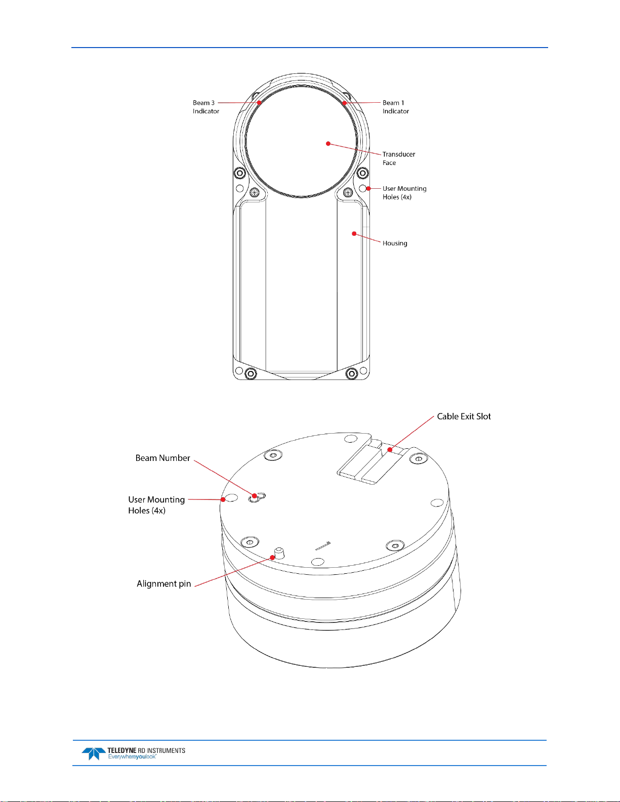
Figure 2. Pathfinder ROV Version Face View
Figure 3. OEM Version Transducer
EAR-Controlled Technology Subject to Restrictions Contained on the Cover Page.
Page 3
Page 16
April 2018 Pathfinder DVL Guide
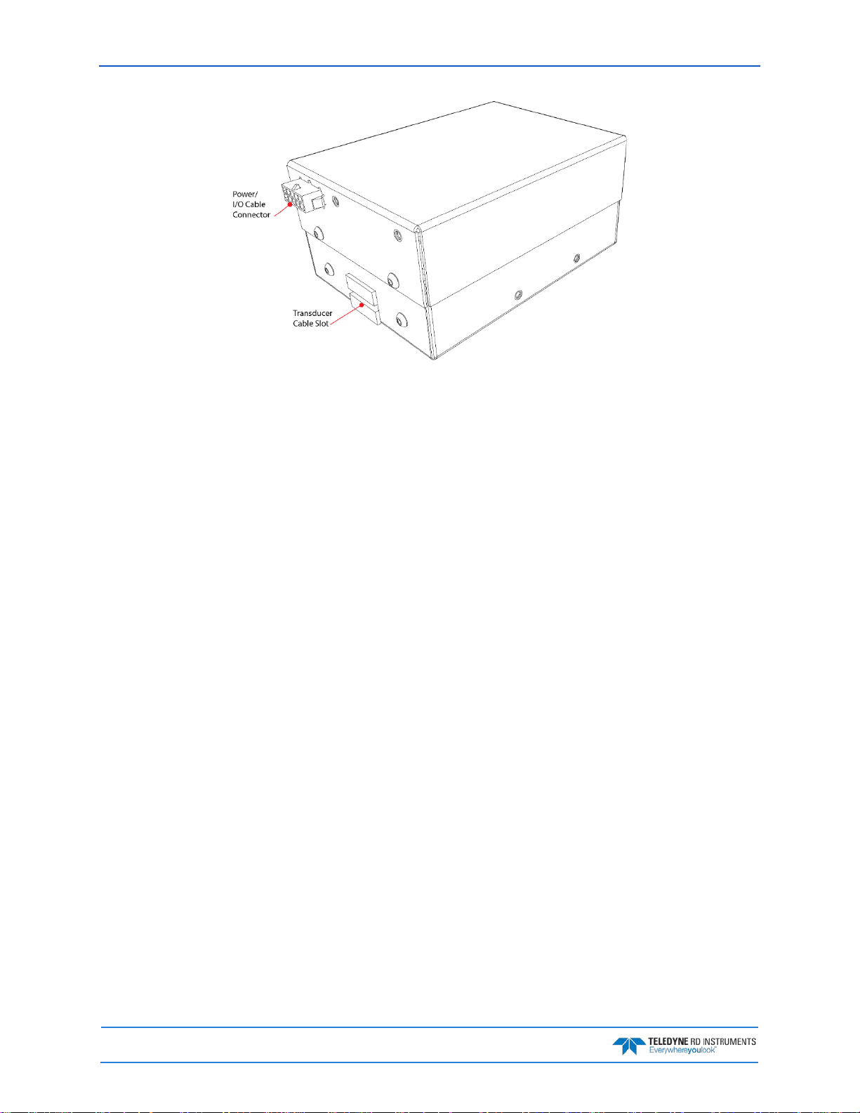
Figure 4. OEM Version Electronics Chassis
Pathfinder Options
The following options are available:
• The 73B-6057-00 ROV test cable is used for testing the system prior to installing it on a ROV.
• The 73b-6059-00 OEM test cable is used for testing the system prior to installing it on a ROV.
• The Ethernet command and control port is included with all systems but can be removed upon
request. This option must be selected when the system is ordered.
• Current Profiling Mode is a firmware upgrade.
• Low-altitude is a firmware upgrade.
• High accuracy Bottom Track is a firmware upgrade.
Page 4
EAR-Controlled Technology Subject to Restrictions Contained on the Cover Page.
Page 17

Pathfinder DVL Guide April 2018
Part Number
Name
Description
The Pathfinder ROV 600 kHz system includes the transducer and connector protec-
face and connectors. Use a soft pad to protect the transducer.
97B-7010-00
ROV hard Shipping Case
Shipping case with foam inserts.
The DVL PWR/COMM pigtail cable allows you to build custom cable to connect the
COM, Power and Trigger.
This CD has PDF versions of all of the Pathfinder DVL software and documentation
can be used to test the DVL.
Inventory
The following DVL Kits are available:
• DVL Standalone: This provides you an option to purchase the DVL with only the necessary parts
to install it in your vehicle. This is especially adapted, once the first integration has been completed and therefore test cables and other accessories are no longer needed.
• DVL Development Package: The DVL Development Package is a complete package to integrate,
evaluate and use your PathFinder DVL. The DVL Development Package was designed to help you
start testing, configuring and integrating your new devices quickly.
• DVL Integration Kit: The DVL Integration Kit has been designed to save you both time and money
by speeding up the evaluation and the integratio n of our products into your vehicle.
• Field Service Kit: The Field Service kit has been designed to allow you to service, repair, and test
your DVL with the assumption that you do not have any kits already available.
Table 1. Pathfinder ROV System Inventory
70B-9042-xx Pathfinder ROV version
73B-6058-00 ROV PWR/COMM Pigtail Cable
95B-6116-00
or
90Z-8002-00
95B-6117-00
95B-6119-00
ROV Spare Parts* See table below for description Anodes and closing hardware
Pathfinder DVL Software and
Documentation CD
Pathfinder ROV Getting Started
Guide
Pathfinder ROV Integration
Guide
tive cap. When unpacking, use care to prevent physical damage to the transducer
Pathfinder to your vehicle/platform. It provides all the leads for serial and Ethernet
including the Pathfinder DVL Guide. Please read the manual! The CD also includes
the TRDI Toolz Software. TRDI Toolz is a utility and testing software package that
A printed quick start card showing test setup is included. A PDF version is included
on the documentation CD.
A printed quick reference showing how to integrate the Pathfinder DVL onto a
ROV. Refer to Chapter 2 of the Pathfinder DVL guide for detailed instructions.
Table 2. Pathfinder ROV Spare Parts*
Description Part number Where used
Anode, housing, top 81B-4146-00
Anode, housing, bottom 810-4106-00
Anode Screw M5X0.8X10FH
Anode Screw M2.5X0.45X8FH
M4 Washer M4WASHSMOD
M4 Split Washer M4WASHSPL
M4 Nylon Washer M4WASHNYLON
M4 Nut M4X0.7NUT
Isolator 91145A148
M4 Bolt M4X0.7X25SH
Anodes for Housing Exterior
Closing hardware for housing
EAR-Controlled Technology Subject to Restrictions Contained on the Cover Page.
Page 5
Page 18

April 2018 Pathfinder DVL Guide
Part Number
Name
Description
97B-7011-00
97B-7012-00
OEM hard Shipping Case
OEM cardboard
The DVL PWR/COMM pigtail cable allows you to build custom cable to connect the
COM, Power and Trigger.
This CD has PDF versions of all of the Pathfinder DVL software and documentation in-
used to test the DVL.
Table 6. 75BK6087-00 – Kit, Field Service, ROV Pathfinder
Table 3. Pathfinder OEM Inventory
70B-9043-xx Pathfinder OEM version
73B-6060-00
95B-6116-00
or
90Z-8002-00
95B-6120-00
95B-6121-00
2-037
5020
OEM PWR/COMM Pigtail
Cable
Pathfinder DVL Software
and Documentation CD
Pathfinder OEM Getting
Started Guide
Pathfinder OEM Integration Guide
O-ring and Lubricant Remote OEM Transducer head O-ring and lubricant
The Pathfinder OEM 600 kHz system includes the transducer and electronics chassis.
When unpacking, use care to prevent physical damage to the transducer face and connectors. Use a soft pad to protect the transducer.
Shipping case with foam inserts.
Pathfinder to your vehicle/platform. It provides all the leads for serial and Ethernet
cluding the Pathfinder DVL Guide. Please read the manual! The CD also includes the
TRDI Toolz Software. TRDI Toolz is a utility and testing software package that can be
A printed quick start card showing test setup is included. A PDF version is included on
the documentation CD.
A printed quick reference showing how to integrate the Pathfinder DVL onto a ROV. Refer to Chapter 2 of the Pathfinder DVL guide for detailed instructions.
Optional Kits
Table 4. 75BK6086-00 – Kit, Integration, ROV Pathfinder
P/N Description QTY
73B-6057-00 Cable, Test, ROV, Pathfinder 1
73B-6046-00 Power cable with banana plugs 1
Table 5. 75BK6088-00 – Kit, Integration, OEM Pathfinder
P/N Description QTY
73B-6059-00 Cable, Test, OEM, Pathfinder 1
P/N Description QTY
M4WASHSMOD WASHER, SMALL OD, 8MM SST 14
M4WASHSPL WASHER, SPLIT LOCK,SST 8
M4WASHNYLON WASHER, FLAT,9MM OD,NYLON 8
M4X0.7NUT NUT, HEX, SST 8
91145A148 ISOLATOR, 1/4 LONG, SCREW #8, NYLON 8
M4X0.7X25SH SCREW, BUTTON/SOCKET HEAD 316 SST 8
81B-4146-00 ANODE, PIONEER 300 2
810-4106-00 ANODE, SMALL OD 4
M5X0.8X10FH SCREW, FLAT HEAD, SST 2
M2.5X0.45X8FH SCREW, FLAT HD SKT HD, 316SST 4
Page 6
EAR-Controlled Technology Subject to Restrictions Contained on the Cover Page.
Page 19

Pathfinder DVL Guide April 2018
Table 6. 75BK6087-00 – Kit, Field Service, ROV Pathfinder
P/N Description QTY
2-152 O-RING, -152, EPDM 70 DURO 2
97Z-6084-01 O-RING, 3-094, .072DIAX.351 ID, EPDM, DURO90A, VENT PLUG 2
7295K1 TIE WRAP, FASTENER MOUNT, 4.5 2
97Z-6007-00 O-RING, 2-011, DURO 70, EPDM 4
97Z-6009-00 O-RING, 2-014 DURO 70, EPDM 2
97Z-6036-00 O-RING, 2-166, 70 DURO,EPDM 2
97Z-6084-00 O-RING, 2-015, 070DIAX.551 ID, EPDM, DURO 90A, VENT PLUG 2
DES6 DESICCANT, SEALED BAG, 1/6 UNI 1
5020 SILICONE LUBRICANT, 4-PACK 2
425 THREADLOCKER, PLAS SCREW 1
81B-6042-00 O-RING TOOL, TELEDYNE 1
M7COMBINATION WRENCH, #7MM COMBINATION 1
7289A13 KEY, HEX, 2.5MM 1
84Z-6000-00 TOOL BAG, CANVA 1
95B-6116-00 Pathfinder DVL Documentation CD 1
95B-6117-00 Pathfinder DVL Quick Start Card 1
Table 7. 75BK6089-00 – Kit, Field Service, OEM Pathfinder
P/N Description QTY
5020 SILICONE LUBRICANT, 4-PACK 2
2-037 O-RING, FACE SEAL, DURO 70 2
84Z-6000-00 TOOL BAG, CANVAS 1
7289A13 KEY, HEX, 2.5MM 1
5503A37 L-KEY, HEX, 2MM 1
81B-6042-00 O-RING TOOL, TELEDYNE 1
95B-6116-00 Pathfinder DVL Documentation CD 1
95B-6117-00 Pathfinder DVL Quick Start Card 1
EAR-Controlled Technology Subject to Restrictions Contained on the Cover Page.
Page 7
Page 20
April 2018 Pathfinder DVL Guide
Health & Environment Monitoring Sensors
Health and Environment Monitoring (HEM) Sensors monitor the health of the Pathfinder system.
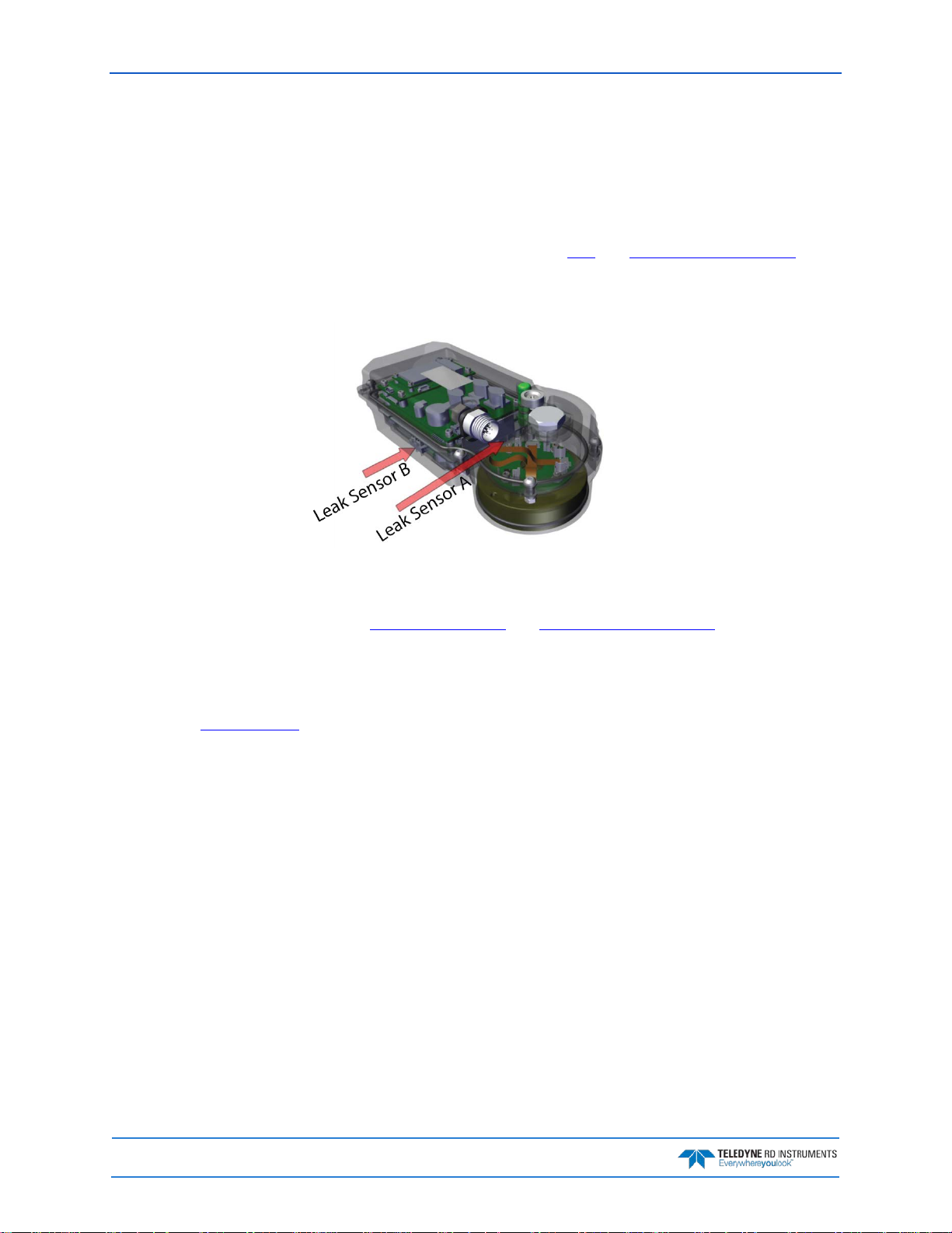
• Leak Detection – Water leaking into a Pathfinder DVL can not only potentially destroy the DVL,
but also cause severe issues for the host vehicle that is carrying the DVL, such as loss of navigation ability. The Pathfinder detects water leaking into the system and reports it in the PD0, PD4,
PD5, and PD6 messages. The Pathfinder also supports the PC4 and PC5 user interactive test for
reporting the status of the leak sensors. There are two leak sensors; One is mounted at the back
of the transducer head and the other at the bottom of the electronic section (Leak Sensor B is
only available on the ROV Self-Contained version).
• Transducer Monitor – The Pathfinder monitors the transmit voltage and current of the transducer
and reports Transducer Impedance as a result. This information provides insight, in near realtime, to the status of the transducer and alerts the user should problems arise. This data is relayed back to the user in the PD0 Bytes 76 and 77 and PD6 output data structure.
• Operating Time – The Pathfinder system records the total time of operation in minutes where
“operation” is defined as the time that the system ping loop is active (CS command has been
sent). The record of the total awake time has a maximum value of 33,554,432 minutes, which
corresponds to over 500,000 hours of operation. The value of the counter can be read as part of
the PS5 command. Although the time is stored in minutes, the operating time is reported in
hours with one decimal place.
Example PS5 output:
PS5
Operating time: 4327.5 hours
Page 8
EAR-Controlled Technology Subject to Restrictions Contained on the Cover Page.
Page 21

Pathfinder DVL Guide April 2018
Windows® 7, 8.1, or 10
Setting up the Pathfinder System
Use this section to connect the Pathfinder to a computer and establish communications. Install the TRDI
Toolz software in order to communicate with the Pathfinder.
Computer and Software Considerations
The Pathfinder system includes the utility program TRDI Toolz to help set up, use, test, and troubleshoot
the Pathfinder. Use this program to “talk” to the Pathfinder and to run script files (see Creating or Modify-
ing Command Files and send the Commands to the Pathfinder). For detailed information on how to use
TRDI Toolz, see the TRDI Toolz Help file.
TRDI designed the Pathfinder to use a Windows® compatible computer. Table 8
puter requirements.
TRDI highly recommends downloading and installing all of the critical updates, recommended
updates, and the service releases for the version of Windows® being used prior to installing
any TRDI software.
Table 8: Minimum Computer Hardware Requirements
1GHz class PC 32-bit (64-bit recommended)
2GB of RAM (4GB or more RAM recommended)
50 MB Free Disk Space plus space for data files (A large, fast hard drive is recommended)
Minimum display resolution of 1024 x 768, 256 color (higher recommended)
CD-ROM Drive (if software is installed from CD)
Mouse or other pointing device
Software Installation
To install the Pathfinder Software and Documentation CD:
1. Insert the CD into the drive.
lists the minimum com-
2. Use Windows Explorer® to open the CD drive folder.
3. Double-click on the launch.exe file. When the browser starts:
• To install TRDI Toolz, click the View Manu al s button and then click the In-
• To view the Pathfinder documentation, click the View Manuals button.
stall TRDI Toolz button.
Many companies require that Autorun be disabled. Double-click on Launch.exe to start the
browser on all TRDI software and documentation CDs.
EAR-Controlled Technology Subject to Restrictions Contained on the Cover Page.
Page 9
Page 22

April 2018 Pathfinder DVL Guide
Power Overview
The Pathfinder requires a DC supply between 10.7 to 36 VDC. Either an external DC power supply or battery can provide this power. The power supply should be able to source at least two Amps for a bench test
setup (no pinging).
Power on Cycle
The power supply must be able to handle the inrush current as well. Inrush current is the current required
to fully charge up the capacitors when power is applied to the Pathfinder. The capacitors provide a store of
energy for use during transmit. The inrush current is as much as four amps if plugged in after the DVL
Transmit Cap is fully discharged. The Pathfinder will draw this amperage until its capacitors are fully
charged (less than 200ms).
If the power supply limits the current or the power drop on the cable is significant, then the
power on cycle will fail or the system will reset during pinging. Therefore, TRDI recommends
a 1.5 to 2 Amp power supply to cover all performance cases. For more information, see
Electrical Specifications.
If the Power is put in then removed within a very short time (few secs) and then applied again,
then the Inrush limiter will not be able to limit the current pulled from the DVL which would
result in a higher than 4Amps Inrush current spike.
Cables and Connector Protective Cap
The underwater cables connector protective cap is a molded wet-mate-able connector. The end-cap connectors are a factory-installed item. TRDI does not recommend removing it for any routine maintenance.
The connector protective cap should be installed any time the cable is removed. Use the
protective connector cap when the DVL is in storage or is being handled.
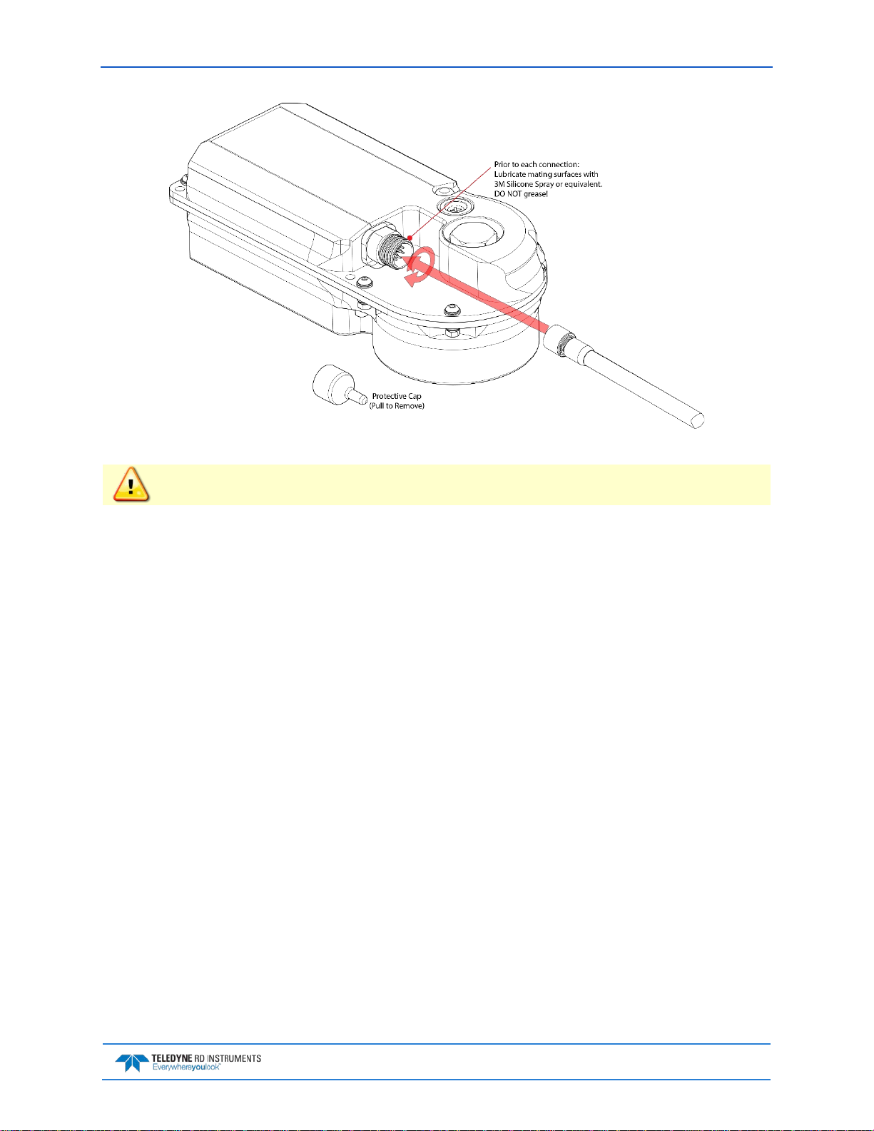
Prior to each connection:
1. Lubricate mating surfaces with 3M Silicone Spray or equivalent; DO NOT grease!
To connect the cable:
1. Check all pins for signs of damage (broken or bent pins or corrosion).
2. The Pathfinder cable connector must be lubricated before each connection.
3. Push the cable straight onto the connector ensuring the pins are properly aligned. While keeping a
slight inward pressure on the cable connector and ensuring that the connector is straight, thread
the locking sleeve onto the receptacle to complete the connection.
Use ONLY silicone based lubricants. DO NOT use petroleum based lubricants.
Do NOT use any tools to tighten the locking sleeve. It should only be “finger tight”.
Page 10
EAR-Controlled Technology Subject to Restrictions Contained on the Cover Page.
Page 23
Pathfinder DVL Guide April 2018
Figure 5. Connecting the Cable
Apply lubricant prior to each connection.
To disconnect the cable:
1. Place the Pathfinder on a soft pad to protect the transducer face.
2. Release the cable by turning the locking sleeve counter-clockwise until it can be moved away from
the connector.
3. Pull the cable straight out away from the housing.
4. Install the connector protective cap to protect the connector pins.
EAR-Controlled Technology Subject to Restrictions Contained on the Cover Page.
Page 11
Page 24
April 2018 Pathfinder DVL Guide
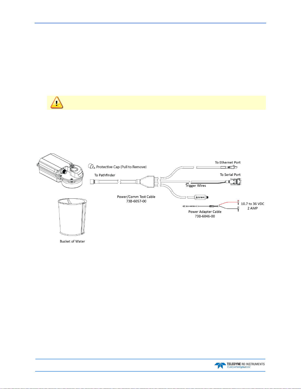
Setting Up the Pathfinder ROV System
To set up the Pathfinder:
1. The Pathfinder cable connector must be lubricated before each connection.
2. Place the Pathfinder on its transducer face on a soft pad. Remove the Power/Comm connector
protective cap and push the cable straight onto the Power/COMM connector ensuring the key and
pins are properly aligned. While keeping a slight inward pressure on the cable connector and ensuring that the connector is straight, thread the locking sleeve onto the receptacle to complete the
connection.
Do NOT use any tools to tighten the locking sleeve. It should only be “finger tight”.
3. Attach the Power/Comm cable to the computer’s serial communication port or Ethernet port.
4. Place the Pathfinder system in water (at least a few inches to cover the transducer face).
5. Connect the power adapter cable to the Power/Comm cable power connector by pushing it all the
way in until it “clicks” and then turn the locking sleeve to secure the connection. Connect +10.7 to
36 VDC power using the banana plugs. The power supply should be able to source at least two
Amps for a bench test setup (no pinging).
Figure 6. ROV Pathfinder Connections for Bench Test [73B-6057-00 & 73B-6046-00 Cables]
Page 12
EAR-Controlled Technology Subject to Restrictions Contained on the Cover Page.
Page 25
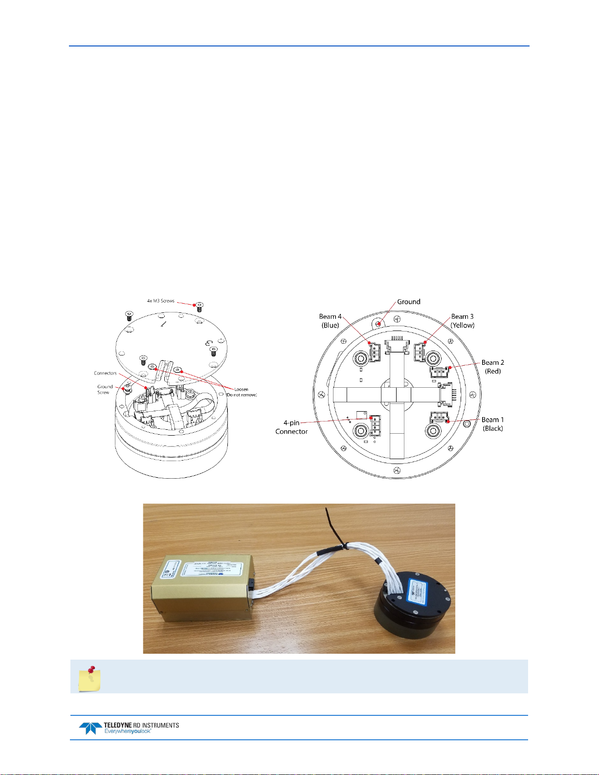
Pathfinder DVL Guide April 2018
Setting Up the Pathfinder OEM System
To set up the OEM Pathfinder:
1. Place the Pathfinder transducer face down on a soft surface.
2. With an ESD wrist strap on, remove the top cover on the transducer. Loosen, but do not remove
the two screws next to the cable exit slot.
3. Connect the five cables and ground wire. The 3-pin beam cables have the beam number on the
connector and are color-coded: Beam 1 = black, Beam 2 = red, Beam 3 = yellow, Beam 4 = blue.
Attach the only 4-pin connector to the board.
4. Remove the screw and attach the ground wire lug. Tighten the ground screw to 4 IN-LB.
5. Thread the cables through the slot and attach the cover. Tighten the four M3 screws on the cover
to 4 IN-LB. Tighten the two screws next to the cable exit slot to hold the cables in place.
6. Connect P1 to the Electronics Chassis.
7. Attach the Power/Comm cable to the computer’s serial or Ethernet communication port.
8. Connect +10.7 to 36 VDC power. The power supply should be able to source at least 1.5 to 2 Amps.
Figure 7. OEM Pathfinder Transducer Connections
The standard length of the cable between the transducer and chassis is 12”.
EAR-Controlled Technology Subject to Restrictions Contained on the Cover Page.
Page 13
Page 26
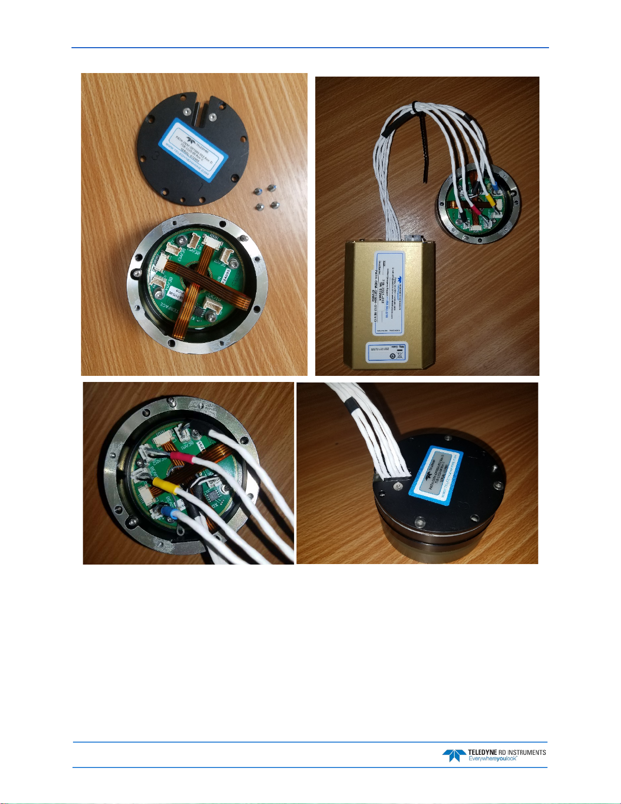
April 2018 Pathfinder DVL Guide
Page 14
EAR-Controlled Technology Subject to Restrictions Contained on the Cover Page.
Page 27
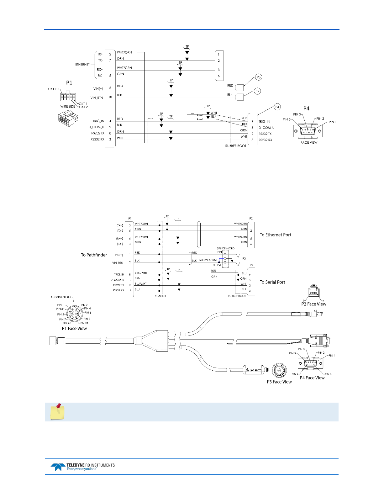
Pathfinder DVL Guide April 2018
Figure 8. OEM Pathfinder Connections for Bench Test [73B-6059-00 Cable]
Cable Wiring Diagrams
This section has information on Pathfinder cabling. Special user-requests may cause changes to the basic
wiring system and may not be shown here. If there is a conflict, contact TRDI for specific information
about the system. The following figures show various Pathfinder cable locations, connectors, and pin-outs.
Figure 9. Pathfinder Power/Comm Cable 73B-6057-005 Optional Test Cable
The connector protective cap should be installed any time the cable is removed. Use the
connector protective cap when the Pathfinder is in storage or is being handled.
EAR-Controlled Technology Subject to Restrictions Contained on the Cover Page.
Page 15
Page 28
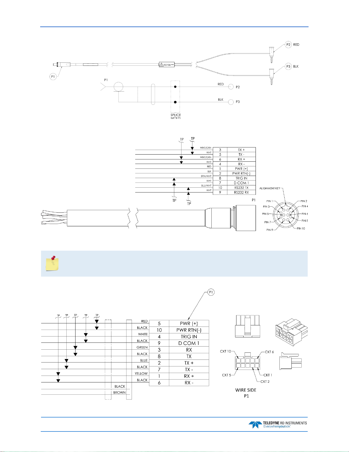
April 2018 Pathfinder DVL Guide
Figure 10. Power Adapter Cable 73B-6046-00
Figure 11. Pathfinder ROV Power/Comm Cable 73B-6058 Pigtail Cable
Where shown, RX is the incoming signal; TX is the outgoing signal.
Cable bend radius is 4.5 inches. The connector part number is MKS(W)-3L10-CCP-SB from
Teledyne Impulse.
Page 16
Figure 12. Pathfinder OEM Power/Comm Cable 73B-6060 Pigtail Cable
EAR-Controlled Technology Subject to Restrictions Contained on the Cover Page.
Page 29
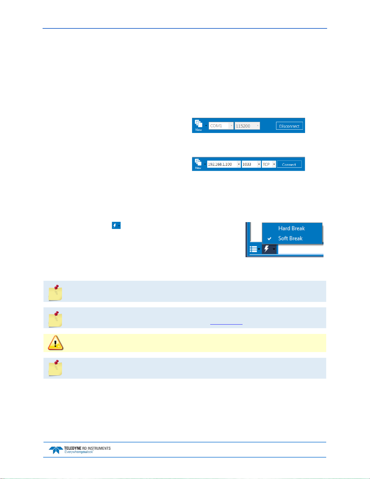
Pathfinder DVL Guide April 2018
Connecting to the Pathfinder
To establish communications with the Pathfinder:
1. Connect the system and apply power.
2. Start the TRDI Toolz software.
3. Select New Serial Connection or New Ethernet Connection.
4. Enter the Pathfinder’s communication settings.
Serial Communications:
Select the COM Port the serial cable is
connected to and set the Baud Rate from
the drop down list to 115200
Ethernet Communications:
Enter the Static
DHCP server IP or host
name 192.168.1.100
Enter the Port Number 1033
Select TCP
5. Click the Connect button. Once connected, the button will change to Disconnect.
6. Click the Break ( ) button. From the Break button drop down
menu, select Soft Break (= = =). The wakeu p banner will display in the terminal window.
Pathfinder
Teledyne RD Instruments (c) 2017
All rights reserved.
Firmware Version: 67.xx
>
It may be necessary to click inside the terminal window and then click the Break button to
wake up the system.
If the network assigns a Dynamic IP address, the Static IP address 192.168.1.100 will not
work; Connect using the serial port and use the CE command to verify the IP address.
You must have the RJ45 connector plugged into the network switch for the CE command to
return the Ethernet setting info.
The command and control port can be Serial or Ethernet, but NOT both. The last port used to
send a break is the command and control port.
7. The LE D shou l d be solid on if no data is moving over the serial port and there is no active TCP/IP
connection on the Ethernet interface.
• The LED will blink 250ms/500ms when there is data on the serial port.
• The LED will blink 250ms/1000ms when there is traffic on the Ethernet port.
EAR-Controlled Technology Subject to Restrictions Contained on the Cover Page.
Page 17
Page 30
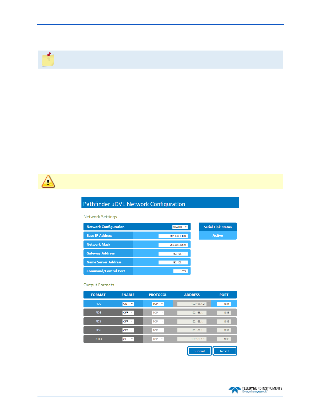
April 2018 Pathfinder DVL Guide
Using the Network Configuration Page
The system must be connected to the Ethernet port to use the Network Configuration page.
To establish communications with the Network Configuration page:
1. Connect the system and apply power.
2. Open a browser on the laptop (Internet Explorer
3. Enter the Pathfinder’s DHCP server IP address 192.168.1.100 into the address bar.
4. On Network Confi g ur ation, choose STATIC or DHCP. Use Dynamic Host Configuration Protocol (DHCP) server protocol when the network automatically provides an Internet Protocol (IP)
host with its IP address and other related configuration information such as the subnet mask and
default gateway.
If you are using a STATIC network, then configure the Base IP Address, Network Mask,
Gateway Address, Name Server Address, and Command/Control Port as needed. The
default configuration is shown in Figure 13.
5. On the Output Formats section, enable or disable the output data formats (PD0, PD4, PD5, PD6, and
PD13), Protocol (TCP or UDP), Address, and Ports. Once done, click Submit.
®
, FireFox®, Google Chrome®, or other browser).
If all outputs are enabled, it can affect the ping rate.
Figure 13. Pathfinder Network Configuration Page
Page 18
EAR-Controlled Technology Subject to Restrictions Contained on the Cover Page.
Page 31

Pathfinder DVL Guide April 2018
Using the Ethernet Communications
Pathfinder systems supports an optional Ethernet output. These systems must be factory configured.
Ethernet can be used for following scenarios:
• Send commands to the ADCP and receive responses on the CMD channel. The CMD channel is
used to connect to a Pathfinder system and control it using a two-letter command system and
must use port 1033. Use TR DI Too l z software to connect to this port using TCP protocols to control the Pathfinder system.
• Send data from the Pathfinder to user equipment such as a PC or a data logging device. The data
channel is established over a UDP socket.
It is possible to output ensemble data in two ways:
1. Send ensemble data to a specific destination IP and port number using TCP protocol.
2. Send ensemble data to a network directed broadcast IP and port number using UDP protocol.
Using TCP Protocol
In the example below a TCP PD0 stream was created on port 1034:
To be able to listen to this stream, you will need to create a TCP connection to the PathFinder DVL IP address, here 192.168.1.100 through port 1034. This can be done in TRDI Toolz for verification.
EAR-Controlled Technology Subject to Restrictions Contained on the Cover Page.
Page 19
Page 32

April 2018 Pathfinder DVL Guide
Using UDP Protocol
In this example below, a PD0 stream was created over UDP on port 1034:
To be able to listen to that UDP stream, you will need to make sure the UDP IP address matches the computer’s IP address. The computer’s IP address can be found using ipconfig in a command prompt window.
The computer’s IP address can also be found by using Control Panel. Navigate to Network and Inter-
net\Network and Sharing Center. Click on Local area Connection x under View Active networks.
Click on Properties and then click on Internet protocol Version 4 (TCP/IPv4). Click on the Prop-
erties button, and then verify the computer’s IP address.
Page 20
EAR-Controlled Technology Subject to Restrictions Contained on the Cover Page.
Page 33

Pathfinder DVL Guide April 2018
In this next example, the computer’s IP address is 192.168.1.2. Therefore, set the UDP IP address on the
web portal to be the same. You can now simply open a UDP stream to listen to that PD0 feed simply by using the port number, here in our example 1034.
This example also includes a PD6 stream over UDP on port 1037 that points to the computer’s IP address
192.168.1.2 – here is the snapshot from listening to this stream using TRD I Too l z:
UDP is a connection-less protocol. Therefore, UDP packets can be lost in an unreliable or
highly congested network.
The Ethernet portion of the DVL acts as a server on (potentially) several fronts:
1. Command/Control of the DVL happens via the TCP port on the command interface (default port
1033). The DVL acts as a server and will accept a connection from any IP on the subnet.
2. Configuration of the PD
X outputs and general IP config happens via the webpage (default IP
192.168.1.100, port 80) (acts as HTTP server).
X output happens on one of several ports:
3. PD
a.
Each PDX (PD0, PD4, PD5, PD6, and PD13) can be configured to be output on a separate
port.
Each can be configured to output via TCP or UDP.
b.
TCP connections can be made from any address – you will connect to the same IP address
c.
as the webpage, and on the specified port. For example, by default only PD0 is enabled.
One would connect a TCP client to 192.168.1.100 at port 1034. The DVL acts as a server
and will accept a connection from any IP.
d. UDP connections will be broadcast by the Ethernet module to the specified Address and
port. By default, these broadcast to 192.168.1.1 on ports 1034 through 1038. For example,
one could configure PD4 to output on UDP, to IP 192.168.1.1 on port 1035, then one would
need a UDP client on a machine at address 192.168.1.1 listening to port 1035. One can
EAR-Controlled Technology Subject to Restrictions Contained on the Cover Page.
Page 21
Page 34

April 2018 Pathfinder DVL Guide
also configure the UDP to use the “broadcast” address such as 192.168.1.255, which would
send traffic to the whole 192.168.1.xxx subnet. The DVL acts as a server and outputs this
data whether a UDP client is connected or not (given the connectionless nature of UDP.)
4. The Ethernet module will NOT act as a DHCP server (can be configured to be a DHCP client, or to
use static addressing). HOWEVER, when configured as a DHCP client, the unit will “failover” to
using the specified “static” IP address (192.168.1.100, by default) if it times out when looking for a
DHCP server. This prevents the unit from being “unreachable” if placed on a network without a
server.
A reminder than in all cases, there MUST be a TCP client connected to the command/control
Address/Port for any of the other PDx traffic to be output. The nominal case would be to
install TDRI Toolz. Select Ethernet Connection, set IP or host name to 192.168.1.100, port
1033 and TCP. This presumes the PC in use is on the same 192.168.1.xxx subnet (since this is
a non-routable IP.)
Ethernet Module Firmware Update
To install an Ethernet module firmware update:
1. Use our online customer portal at http://www.teledynemarine.com/rdi and click on the Support
link to download the firmware update. Log into your account and then click the Software/Firm-
ware link. Save the file to the computer and unzip the file. The file wil l be PF_xx.xx.xx.xx.bin for-
mat where xxxx = firmware version.
2. Connect to the Pathfinder Network Configuration Page.
3. On the upper right corner, select Update.
4. Click the Choose file button and locate the firmware file PF_xx.xx.xx.xx.bin file downloaded in
step 1. Select the file and click Update.
5. The firmwar e wil l ins t al l.
6. Once the firmware update is complete, the Pathfinder will reboot. Close the browser and reconnect to the Pathfinder Network Configuration Page.
7. If the new firmware does not install, contact Customer Service.
Page 22
EAR-Controlled Technology Subject to Restrictions Contained on the Cover Page.
Page 35

Pathfinder DVL Guide April 2018
Testing the Pathfinder System
To test the Pathfinder:
1. Interconnect the system as described in Setting Up the Pathfinder System.
2. Place the Pathfinder transducer in water (at least a few inches to cover the transducer face).
3. Apply power to the system.
4. Start the TRDI Toolz program (for help on using TRDI Toolz, see the TRDI Toolz Help file).
5. Click the Break button. The wakeup banner appears on the log file window.
Pathfinder
Teledyne RD Instruments (c) 2015
All rights reserved.
Firmware Version: 67.xx
>
6. At the “>” prompt in the communication window, enter the command CR1 then press the Enter
key. This will set the Pathfinder to the factory default settings.
7. At the “>” prompt in the communication window, enter the command CK then press the Enter
key. This will save the factory default setting.
8. At the “>” prompt in the communication window, enter the command PS0 then press the Enter
key. This will display the Pathfinder system configuration data.
>ps0
Serial Number: 0
Frequency: 614400 Hz
Configuration: DVL : 4-beam velocity.
Transducer Type: PHASEDARRAY
Beam Angle: 30 Degrees
Beam Pattern: CONVEX
Sensors: TEMP
CPU Firmware: 67.00c MH0
FPGA Version: 1.00.003 [0x1003]
Board Serial Number Data:
FF 00 00 08 0A 1A E1 28 DS18B20 TMP SNS
52 00 00 02 7B 85 3C 23 ETH72B-2305-00A
5F 00 00 02 61 E5 71 23 DSP72B-2303-00A
B5 00 00 02 1A 90 C3 23 PTX72B-2304-00A
C3 00 00 02 63 57 0B 23 RCV72B-2302-03A
C6 00 00 02 7B 8C F7 23 XDC72B-1110-00B
9. At the “>” prompt in the communication window, enter the command PA then press the Enter
key. This will run the Pathfinder Pre-Deployment test.
Submerge the transducer face in a few inches of water. The PA test may fail in air. Only a
failure with the transducer in water is a relevant test.
This test may fail if the Pathfinder is exposed to electrical interference such as that from
other acoustic devices or SONARs or other electronic devices (i.e. cellphones, radios,
computers, TV’s, etc.). The test may also fail if the Pathfinder or its cable is exposed or
installed near potential sources of EMI’s such as high voltage lines like main engine cables,
galley equipment, winches, engine room equipment, cranes, high voltage lighting circuit, etc.
Interference from the mentioned sources may contaminate the Pathfinder’s data as well.
Oftentimes, a noisy (i.e. non-UPS) power supply may cause failures in this test as well.
EAR-Controlled Technology Subject to Restrictions Contained on the Cover Page.
Page 23
Page 36

April 2018 Pathfinder DVL Guide
>PA
ROM Test...PASS [ 3aad ]
RAM test...PASS
FRAM test...PASS
Receive Buffer Test...PASSED
XMIT RAM Test....PASSED
Receive Path Test (Hard Limited)...PASSED
Transmit/Receive Continuity Check...PASSED
Composite Result:
GO for Deployment
10. If the wakeup displays, PS0 displays, and PA message displays with a result of “GO for Deployment”, the Pathfinder is functioning normally.
11. If the result shows “NO-GO for deployment” then run a PT200 test to obtained a more detailed
log of the failure. See Troubleshooting EMI for more information.
Caring for the Pathfinder System
This section contains a list of items to be aware of every time handling, using, or deploying the Pathfinder.
Please refer to this list often.
General Handling Guidelines
• Never set the Pathfinder transducer on a hard or rough surface. This may leave an indentation in
the urethane or damage the urethane face, anodized finish, or paint.
• Do not expose the transducer face to prolonged sunlight (24 hours or more). The urethane face
may develop cracks. Cover the transducer face on the Pathfinder if it will be exposed to sunlight.
• Do not store the Pathfinder in temperatures over 60 degrees C or under -25 degrees C. The inter-
nal components and/or urethane face may be damaged.
• Do not scratch or damage the O-ring surface or grooves on the transducer. If scratches or damage
exists, they may provide a leakage path and cause the Pathfinder to flood. Do not risk a deployment
with damaged O-ring surface.
• Do not lift or support a Pathfinder by the external cables. The connector or cable will break.
• Apply lubricant prior to each cable connection. Regular lubrication is required: Apply silicone lubri-
cant prior to each connection.
• Do not connect or disconnect the cables with power applied. When the cable is connected with
power applied, it may cause a small spark. The connector pins may become pitted and worn.
• The cables may be connected while slightly wet; do not connect under water.
Installation Guidelines
• Loose, missing, stripped hardware or damaged O-rings can lead to water ingress and damage the
Pathfinder.
• Do not connect other metal to the Pathfinder. Other metals may cause corrosion damage. Isolating
bushings must be used when mounting the Pathfinder to a metal structure if the transducer is
bolted to the vehicle.
Page 24
EAR-Controlled Technology Subject to Restrictions Contained on the Cover Page.
Page 37

Pathfinder DVL Guide April 2018
Chapter 2
SYSTEM INTEGRATION
In this chapter, you will learn:
• DVL Theory
• Mechanical Integration Considerations
• Electrical Integration Considerations
• Acoustic Integration Considerations
• Reference, Data & Timing Considerations
• PathFinder DVL Sensor Integration
• Operational and Setup Considerations
EAR-Controlled Technology Subject to Restrictions Contained on the Cover Page.
Page 25
Page 38

April 2018 Pathfinder DVL Guide
System Integration Introduction
This chapter is intended to provide both the basic operating theory and the necessary and often critical
implementation and integration considerations for the use of DVL systems on various platform types. In
addition, the procedures described provide a step-by-step guide that will enable the client to configure
the Pathfinder DVL sonar for optimum utilization.
DVL Theory
BroadBand Doppler
Doppler sonars by definition, measure the Doppler shift, i.e. the frequency shift due to the relative motion
of the DVL to either the seabed or suspended scatter particles in the water column. TRDI uses a more precise method of measurement that is a refinement to standard Doppler phase shift measurements called
BroadBand. The methodology uses time dilation, by measuring the change in arrival times from successive acoustic pulses. TRDI uses phase to measure time dilation instead of measuring frequency changes
because the phase measurement gives a more precise Doppler shift measurement.
TRDI also incorporates a technique called autocorrelation for error checking and thus a further refinement of velocity measurements. Autocorrelation works by transmitting a series of coded pulses, all in sequence and inside a single long pulse. The resulting received signal is composed of many echoes from
many scatterers, all combined into a single echo. The propagation delay is extracted by computing the autocorrelation at the time lag separating the coded pulses. The success of this computation requires that
the different echoes from the coded pulses (all buried inside the same echo) be correlated with one another.
Bottom Tracking
Bottom tracking is implemented using separate pings from water profiling. The transmit pulse is a longer
duration, and the received acoustic signal incorporates a different processing scheme.
While water-profiling uses short transmit pulses to obtain vertical resolution, Bottom Tracking requires
long duration pulses. Long pulses are utilized because this provides ensonification over a lager bottom
area for each individual pulse (Figure 14).
If the pulse is too short or long, the echo returns first from the leading edge of the beam, followed later by
the trailing edge. Because the beam has a finite beam width, the angle of the beam relative to the horizontal is different on these two edges, thus resulting in a Doppler shift that is different from one side of the
beam to the other. By illuminating the bottom across the beam all at once, a long pulse produces an accurate and stable estimate of velocity, more accurate than is typically obtained from water profiles.
The disadvantage of long transmit pulses is that a considerable part of the echo can come from watermass echoes. Where water-mass echoes are weak relative to the bottom echo, there is no adverse impact.
For environments with high concentrations of suspended sediment (i.e. in some rivers) the water-mass
echoes can introduce significant water bias. The added water bias causes an undesirable shift of the bottom-track velocity toward the ambient water velocity.
Page 26
EAR-Controlled Technology Subject to Restrictions Contained on the Cover Page.
Page 39

Pathfinder DVL Guide April 2018
Figure 14. Short Pulse versus Long Pulse
A long Pulse is needed for the beams to ensonify (illuminate) the entire bottom all at once.
Water Tracking
Water tracking is used when the bottom is out of range or a reference velocity is desired. All TRDI DVLs
are configured to provide Water Tracking data. Water tracking is desirable in situations where the bottom
is not always within range of the DVL because of suspect Bottom Track data. The BK command configures how often water track pings are sent. The number of Water Track pings per ensemble is dependent
on the BP-command (bottom pings per ensemble) and this command setting. Water track pinging is activated from the BL command. Use the BL command to set the location of the Water Track ping.
Required Conditions for Water Tracking
Water Track ping output data is available when both the BK (Water-Mass Layer Mode) and BP (BottomTrack Pings pe r E ns e m ble) in st rument setti n gs a re no nz er o va lues. The bottom must be at least the Minimum Layer Size + Near Layer Boundary + 20% of the reported depth away from the transducer. The Far
boundary cannot exceed 80% of the range-to-bottom of the beam with the shortest altitude. If the bottom
comes up so that the Far boundary does not meet this requirement, then the Far boundary is automatically adjusted to ensure this requirement is met, unless the minimum layer size cannot be maintained, in
which case the water track ping is skipped and the data is marked bad.
Figure 15. Water-Mass Layer Processing
EAR-Controlled Technology Subject to Restrictions Contained on the Cover Page.
Page 27
Page 40

April 2018 Pathfinder DVL Guide
Water Tracking Parameters
The parameters for DVL Water Tracking feature is either preset in the instrument default mode or user
defined (see the BK command and Table 21, page 108). The user-defined Water Track ping layer is used
unless the layer comes within 20% of the water boundary (sea floor for down-looking systems; surface for
up-looking systems). As the user-defined Water Track ping layer comes within 20% of the boundary
(Figure 15, B), the layer compresses in size until the minimum water-mass layer size is reached. No Water
Track ping will be sent when the boundary exceeds the 20% limit (Figure 15, C).
The water-mass layer is operational only if BP > zero and BK > zero.
Current Profiling
The Pathfinder DVL has optional firmware configurations that enable the instruments to measure current
velocities in th e wa t e r co l u mn . The DVL, as with all TRDI ADCPs, measures current by dividing the velocity profile into uniform segments called depth cells (depth cells are often called bins). Each depth cell is
comparable to a single current meter. Therefore, a DVL velocity profile is like a string of current meters
uniformly spaced on a mooring (Figure 16). Thus, we can make the following definitions by analogy:
Depth cell size = distance between current meters. Number of depth cells = number of current meters
Figure 16. DVL Depth Cells for Current Measurements
The water profile data used for current measurements includes the four different kinds of standard profile
data shown below. These data types can be incorporated to varying degrees, depending on the user requirements and mission.
• Velocity – as measured from the Doppler shift of the individual beams of the DVL/ADCP.
• Echo intensity – A byproduct of the ADCP system. Sometimes used to measure relative sedi-
ment, plankton or other suspended particle quantities.
• Correlation – an indicator of the fidelity of the ping echo, used for QA.
• Percent good – percent of pings that meet specified quality thresholds used for QA.
Page 28
EAR-Controlled Technology Subject to Restrictions Contained on the Cover Page.
Page 41

Pathfinder DVL Guide April 2018
Beam Coordinate Systems
The Pathfinder can produce velocity measurements in any of the following four sets of coordinate axes by
setting the EX command. Except for the first, they are all right-handed orthogonal systems. The user operational requirements dictate the best coordinate system to be used.
Earth Axis, also known as Geographic or Geodetic Coordinates. (E, N, U) Earth Axis are selected (default set-
ting) with command EX11xxx. These axes are named east, north, and up. Strictly speaking, these terms
refer to true orientations, although magnetic orientations are often used instead. This is the most commonly used coordinate system because it provides a stable reference frame for ensemble averaging.
Radial Beam Coordinates. (BM1, BM2, BM3, BM4) Radial Beam Coordinates are selected by the EX00xxx
command. These are the “raw” velocity measurements measured independently by each transducer, in
units of millimeters per second. The sense is positive when the motion is towards the transducer. These
axes are not orthogonal.
Instrument Coordinates. (X, Y, Z) Instrument Coordinates are selected by the EX01xxx command. This set
of axes is always oriented the same relative to the transducer head. Looking at the end view of the housing, the transducers are labeled clockwise in the order 3-2-4-1 (Figure 17). When you look at the face of
the transducer head, the transducers are labeled clockwise in the order, 3-1-4-2 (see Figure 18, page 30).
The X-axis lies in the direction from transducer Beam 1 towards transducer Beam 2 and the Y-axis lies in
the direction from transducer Beam 4 towards transducer Beam 3. The Z-axis lies along the axes of symmetry of the four beams, pointing away from the water towards the housing.
The PD0 Bottom Track output data format assumes that the instrument is stationary and the
bottom is moving.
• If Beam 3 is going forward, then the Y
velocity is negative.
• If Beam 2 is going forward, then X ve-
locity is negative.
• If the bottom is going towards the face
of a down facing DVL, then Z is positive.
The PD3 through PD6 data formats assume that
the bottom is stationary and that the DVL or
vessel is moving.
• If Beam 3 is going forward, then the Y
Figure 17. X, Y, and Z Velocities (ROV version
shown)
velocity is positive.
• If Beam 2 is going forward, then X ve-
locity is positive.
• If the bottom is going towards the face
of a down facing DVL, then Z is negative.
Ship Coordinates (or Righted Instrument Coordinates). (S, F, M) Ship Coordinates ar e selected by the
EX10xxx command. TRDI uses the names Starboard, Forward, and Mast, although these axes are more
commonly called the roll, pitch, and yaw-axes, respectively. Assuming that Beam 3 is aligned with the keel
on the forward side of the DVL, for the downward-looking orientation, these axes are identical to the instrument axes:
S = X, F = Y, M = Z
For the upward-looking orientation, these axes are rotated 180° about the Y-axis:
S = -X, F = Y, M = -Z
EAR-Controlled Technology Subject to Restrictions Contained on the Cover Page.
Page 29
Page 42

April 2018 Pathfinder DVL Guide
Sign of Angle for a Unit Facing
Up
Down
Tilt 1 (Pitch) Beam 3 higher than Beam 4
+
+
Tilt 2 (Roll) Beam 2 higher than Beam 1
+
-
The M (mast) axis points in a direction that is closer to upward than downward (mast is always in the
same direction no matter if looking down or up).
Figure 18. Pathfinder Ship Coordinates (OEM Transducer Shown)
The importance of the ship axis is that the attitude angles (pitch, roll, and heading) measure the orientation of the ship axes relative to the earth axes, regardless of up/down orientation. The sense of internal
sensors Tilt 1 (pitch) and Tilt 2 (roll) is positive for counterclockwise tilts respectively about the S and F
axes, using the right-hand rule (see Figure 19). One can use the Ship Frame and the alignment commands
to align the DVL Ship axis with the vehicle/platform Ship axis. See Mechanical Integration Considera-
tions for more information, and see the EA and EP commands. In addition if Tilts are fed to the DVL then
the DVL Ship Frame is then Level.
Figure 19. Pathfinder Pitch and Roll
Page 30
EAR-Controlled Technology Subject to Restrictions Contained on the Cover Page.
Page 43

Pathfinder DVL Guide April 2018
DVL Performance and Influencing Factors
Long Term Performance
TRDI specifies the long-term velocity error of its DVL products as a combination of a percentage of speed
(known as “scale factor error”) and an offset (e.g., ±0.3% ±0.2 cm/s for the Pathfinder 600 kHz bottom
track measurement). The water- and bottom-track versions have the same form but may have somewhat
different values. For water track, the first term scales with the speed through the water (the magnitude of
the vector difference between current and boat velocity). For bottom track, it scales with the magnitude of
the boat velocity over the bottom.
Almost all known bias mechanisms (other than rounding error) in DVLs approach zero as the speed approaches zero, although it is difficult to demonstrate this empirically. (Note that when the speed is exactly
zero, frozen short-term error can look like bias.) The offset specification term should not be interpreted as
the standard deviation of the bias at zero velocity, but rather as a way of accommodating non-linear behavior such as biases that oscillate with velocity or that give an increased scale factor bias at low velocity.
The long-term error is also known as systematic error or bias. If we assume that the predictable component of the long-term error has been subtracted out, then the long-term error can be considered to have
zero mean, although it may be non-stationary, in which case the mean may not exist. An example of a bias
that can be subtracted out is the beam pointing error, which can be removed using a calibrated beam-toinstrument transformation matrix. A calibration always leaves some small residual uncertainty, which can
be considered to be another source of long-term error.
When measuring velocity, the bias represents a small error. When using these velocities for navigation the
bias errors will accumulate and the total error will grow over time. This bias error can be mitigated using
various approaches; TRDI can offer application support in this area.
Bottom Track
The most important source of long-term bottom track error is the beam angle error. TRDI measures this
error and provides a beam correction matrix that reduces this error to within the system’s specified accuracy. Improvements in both scale factor and azimuth errors can be made by doing a more extensive calibration on the platform.
The bottom track velocity measurement is proportional to the speed of sound in water. Any error in the
sound speed used in the DVL’s internal signal processing (for example errors in the temperature reading
or salinity setting) propagates directly into scale factor error. Therefore, it is important to program an accurate salinity into the unit (the DVL has a temperature sensor). Another approach to minimizing sound
speed is to incorporate a speed-of-sound sensor. This external reading of the speed of sound can be sent to
the DVL, or the DVL’s sound speed can be set to a constant value and then post-processed to correct the
data for the actual sound speed in the navigation system software. For most applications, setting the salinity accurately and using the DVL’s integrated temperature sensor is sufficient to yield highly accurate
readings.
Water Track
Water Track accuracy is susceptible to the same error sources outlined above. The first term for long-term
accuracy is determined only by the uncertainty of the beam angles, which is the same for water profile,
water track, and bottom track. Thus, one can use the same Long Term accuracy as presented for Bottom
Track above for water profile and water track. When using the Water Layer mode one must also be aware
of the water movement, i.e. currents will be an additional source of error.
EAR-Controlled Technology Subject to Restrictions Contained on the Cover Page.
Page 31
Page 44

April 2018 Pathfinder DVL Guide
meters 10
SizeLayer
Water
shown
Dev. Std.
Dev. Std. =
SoS)cos(
altitude
8Time Ping Minimum
⋅⋅=J
Short Term Performance
Short-term errors are random errors with short correlation times that quickly average to zero. They are
characterized by the standard deviation. The short-term error in each beam is independent of that in
every other beam. Except at very slow speeds, the short-term error in each ping is independent of that of
every other ping. The correlation distances at very slow speeds are not accurately known. As the name indicates, the short-term error will reduce the accuracy of instantaneous velocity readings but over larger
intervals of time, these errors will not affect the average velocity reading or navigation.
Bottom Track
The standard deviation of the bottom track velocity measurement varies with altitude and can vary with
velocity. The default modes have two primary sub mo des, one for shallow water at low speed (Bottom
Mode 8) and one for other cases (Bottom Mode 9).
The Pathfinder standard deviation performance depends on altitude. It generally decreases as the altitude
gets greater and increases as the altitude gets lower. At the lower altitudes, it increases inversely with altitude. Below these altitudes, the systems attempt to change modes and if successful, the standard deviation
drops considerably as the Pathfinder flies below its deep switching altitude and then again when it flies
below its shallow switching altitudes.
Water Track
The standard deviation of the velocity measurement for Water Layer will vary as the size of the Water
Layer varies – see the descriptions for the #BL command to determine the Water Layer size and the following equation:
Pathfinder DVLs have the capability to compute velocities off of a water track layer while Bottom Tracking. The commands for controlling this mode are #BK & #BL for Pathfinder DVLs. However, there are
some important consequences of enabling this mode that will be discussed.
First, the time requ ired to com plete a ping is si gnif icantl y incr eas ed because two separate and independent pings are involved. TRDI does not currently have ping time models for the Water Track ping.
If required, the times would have to be obtained experimentally.
Secondly, there is the opportunity for ping-to-ping interference when the Water Track is enabled. After
transmitting an acoustic pulse, the Pathfinder DVLs open their receivers and listen for a return (either
from the bottom for a Bottom Track ping or from the water c olumn fo r a Water Tra ck ping ). The return
MUST be from the particular ping that is tra nsmitted. If it is from a previous ping, interference results
and the system might not work at all, or worse, m ight g iv e err on eous res ult s.
For example, on a Bottom Track ping, a return from the bottom from the previous Water Track ping
might look like the return from the Bottom Track ping, but at the wrong altitude. The problem is usually
worse when usin g Wa t er Track and the previous Bottom Track ping is the cause of the interference. The
return from the Bottom Track ping is usually much larger than that from water scattering and when the
operating altitude is low, that return can make several round trips from the bottom to water surface to the
bottom again and still be large enough to cause interference with the Water Track ping. TRDI recommends that the time between pings be set so that there is enough time for each ping to travel four
round trips to the bottom and back when the altitude is significantly less than the specified operating altitude. This time can be calculated by doubling the altitude and then dividing by the Cosine of the Janus
angle (normally 30°) and then dividing by the speed-of-sound and multiplying by four.
Page 32
EAR-Controlled Technology Subject to Restrictions Contained on the Cover Page.
Page 45

Pathfinder DVL Guide April 2018
When operating at altitudes approaching the altitude capability of the DVL, the ping time should be:
Minimum Ping Time > 1.5 times the round trip time at the maximum specified operating altitude.
The long-term and short-term accuracy characteristics of the Water Track mode a r e di sc u ss ed in the re-
spective accuracy sections of this docum ent .
Altitude Performance
The altitude (distance above the bottom) capability of TRDI DVL’s is influenced by:
• Bottom type
• The average temperature and salinity of the water column from the DVL to the bottom
• The voltage supplied to the system
• The attitude of the DVL
• Bottom slope
TRDI specifies this altitude capability for:
• A typical bottom type being level
• A temperature of 5° C, a salinity of 35ppt
• An input voltage of 24v for Pathfinder DVLs
• ±5° vehicle pitch or roll
Changes in these values will affect the altitude capability as discussed below.
Bottom Type & Slope
Robert J. Urick (3
grazing angle. This analysis shows that the scattering strength of botto ms can vary fr om a pproxi mately -10d B for bottoms of “sand and rock” to -40dB for “muddy” bottoms. A higher value (less negative) of backscatter strength means that the refl ected signal from t he bottom is l arger and that the
DVL will operate to greater altitudes. TRDI uses a reasonably conservative value of -28dB for the prediction of a DVL’s altitude performance. While our experience shows that this works in most environments, bottoms that are “bright” (some ro cks and/or gra vel) will allow the DVL to operate to
higher altitudes while bottoms that are “dull” (mud) will limit operation to somewhat lower altitudes
than are specified. In general, a 1dB change in backscatter strength will affect the altitude capability of a
DVL by approximately 4m and 2m for 300 kHz and 600 kHz Pathfinders respectively. Larger (less
negative) v alues increa se t he a lt it u de c a pa b ility. Bottom slope also strongly affects the return.
rd
edition, 1983) shows curves of backscatter strength vs. bottom type, frequency, and
Temperature & Salinity
The transmitted acoustic pulse from a DVL is attenuated as a function of range due to a phenomenon
called absorption. Absorption is caused by the conversion of some of the transmitted acoustic energy being converted to heat while traveling through the water. This lowers the available energy for the detection
and processing of the reflected pulse from the bottom and affects the DVL’s altitude capability. This absorption loss is influenced through complex physics by the frequency and the average temperature and
salinity of the water column.
The 600 kHz systems are minimally affected by temperature and salinity changes. The 300 kHz system is
slightly affected by an increase in temperature and salinity. Warmer temperatures continue to degrade its
performance. Operation in fresh water enhances a DVL’s altitude capability; in general low-salinity waters
will increase the operating range of the unit.
EAR-Controlled Technology Subject to Restrictions Contained on the Cover Page.
Page 33
Page 46

April 2018 Pathfinder DVL Guide
Pitch & Roll
The distance to the bottom of a transmitted pulse for a given beam is a function of the angle of the beam
to the vertical. As the vehicle pitches and rolls, this angle can be dif ferent for t he fou r bea ms. Some
beams will have further to travel and others will have less. The bottom slope has similar effects . The
transmitted energy density of the bottom track pulse is attenuated as it travels through the water column and the further it has to travel, the smaller the energy that is left for detection. As a result, the
altitude capability of a DV L may be red u c ed b y t he e f fec ts of bottom slope, pitch, and roll.
Transmit Power
The altitude capability of a DVL will vary as the input voltage to the system varies. Table 9 below gives an
approximation of the range versus battery voltage.
Table 9. Pathfinder Nominal Voltage versus Bottom Tracking Range with Ethernet
Vin
V
10 170 1.70 445 4.45 1.95 0.16 74
12 144 1.73 498 5.98 2.11 0.29 77
Idle
current
mA
Idle
Power
W
Peak
Current
mA
Peak
Power
W
Average
Power
W
(estimate)
XMIT
Power
W/Beam
BT Range
(m)
16 108 1.73 576 9.22 2.40 0.63 82
20 88 1.76 618 12.36 2.71 1.6 86
24 74 1.78 664 15.94 3.05 1.8 89
30 64 1.92 750 22.50 3.77 2.9 92
32 62 1.98 785 25.12 4.07 3.3 93
36 58 2.09 857 30.85 4.68 4.5 95
Slant Range Performance
The accuracy of the altitude measurement of TRDI DVL’s is not specified but has been shown to be less
influenced by environmental factors. It is important to know that the systems do not measure the altitude
by using a beam that is directed straight down as an altimeter might do. Rather, they measure the “slant
range” along the four narrow beams that are at an angle to the vertical (normally 30°). In doing this, they
measure the time it takes for the transmitted pulse to travel to the bottom, be reflected, and travel back to
the instrument. This time is then multiplied by the speed of sound that either the user enters or is computed from the temperature and salinity data that the instrument has. The “slant range” is then projected
into the vertical by multiplying by the Cosine of the Janus angle (normally 30°). Naturally, each beam’s
measurement of this “slant range” will change as the environment changes. These changes include vehicle attitude (pitch and rol l), bottom slo pe, and changes in the speed of sound. The next sections discuss the errors that these environmental changes cause. This is followed by a brief discussion of the additional, improved outputs that the Pathfinder DVLs provide.
Speed of Sound Variation
As the speed of sound changes through the water column either due to temperature or salinity changes,
the time it takes for the round-trip travel time changes. For example, a decrease in sound speed will cause
an increase in travel time and the instrument (not knowing about the change in sound speed) will
interpret this as a longer “slant-range”. A somewhat mitigating effect is that the beams will refract as the
sound speed changes. For example, a decrease in sound speed will refract the beam towards the vertical
Page 34
EAR-Controlled Technology Subject to Restrictions Contained on the Cover Page.
Page 47

Pathfinder DVL Guide April 2018
4
4321
hhhh
h
+++
≈
h
h
h
h h
h
h
h h
h h h
h
1 1
1 1 1 1
=
+
+
+
=
+
+
+
1 2 3
4
1
2
1 2
3 4
3 4
θββφφ
2
2
2
1
2
2
1
tan1 −±+≈
∆
h
h
which decreases the distance the pulse has to travel and this partly offsets the change in travel time.
This error is difficult to calculate because one needs to know the actual speed of sound profile in the
water column. A couple of examples are given below:
Example 1: A linearly changing temperature from 15°C at the instrument to 4°C at 250m depth will cause
the “slant range” measurement to read high by about 1% at an altitude of 250 meters.
Example 2: A step change in temperature of 10°C at a depth of 50 meters will increase the “slant range”
measurement a little less than 1% when operating at 100m altitude.
Bottom Slope
Pathfinder DVLs multiply the measu red “slant range” of each beam by the Cosine of the Janus angle
(normally 30°) to indicate the vertical distance. While a simple solution is to average the four beam values
obtained for altitude, this is not the preferred method. The equation for this is shown as (1) below. This is
reasonably accurate when there is no bottom slope, but a better algorithm is shown in (2) belo w for bottoms that are sloped.
(1)
(2)
Where h is the altitude and the h1, h2, h3, h4 are the four beam “slant ranges” projected into the vertical.
This equation is exact if the bottom is a plane surface.
Pitch & Roll
Pitch and/or rol l o f the instrument c aus es t he h comp onents show n in (1) above to change. Because it is
complicated to compute the h components for all combinations of pitch, roll, and bottom slope, the worst-
case relative error as calculated by equation (1) above is used and is approximately:
where β is the bottom slope in radians,
φ
θ is the beam Janus angle.
This method is used in the case that tilts and bottom slope are in the same direction. Note that the error is
second order in the bottom slope and tilt parameters. An 8-degree tilt will cause the simple four-beam average to be 1% long. A 14-degree bottom slope will cause it to be 1% short (when the beam Janus angle is
30
is the instrument tilt in radians, and
0
).
Resolution
The Pathfinder DVLs provide two additional altitude outputs in the Bottom Track Range Format. The first
is called “Slant Range” w hich is actually a range to the bottom i n the Z-axis. It is a combination of
the four slant ranges per equation (2) above. The second is called “Vertical Range” where the instrument
pitch and roll are used to calculate the altitude. This is the most accurate output for altitude since it
compensates for the orientation of the instrument.
EAR-Controlled Technology Subject to Restrictions Contained on the Cover Page.
Page 35
Page 48

April 2018 Pathfinder DVL Guide
Mechanical Integration Considerations
Alignment
The mechanical alignment of the transducer head is important to DVL data accuracy. Mechanically mount
the head as close as possible to your reference point. This is usually with the Beam 3 mark at 0° or 45° relative to the ship’s fore-to-aft centerline. You also must mount the transducer head as level as possible using the ship’s roll and pitch references.
TRDI recommends mounting the transducer head with Beam 3 (instrument Y-axis) rotated 45° relative to
the ship forward axis (Figure 20). This causes the magnitude of the signal in each beam to be about the
same. This improves error rejection, reduces the effect of ringing, and increases the Pathfinder’s effective
velocity range by a factor of 1.4. If Beam 3 is aligned at an angle other than zero, use the EA command to
describe the rotation between instrument Y axis (beam 3) and ship forward axis. Refer to EA - Heading
Alignment.
Figure 20. Transducer Alignment Reference Points
Page 36
EAR-Controlled Technology Subject to Restrictions Contained on the Cover Page.
Page 49

Pathfinder DVL Guide April 2018
Beam Clearance
Acoustic obstacles such as cables, hull, other instruments, etc. are numerous on undersea vehicles. Special
care should be observed in clearing the DVL beams of any acoustic obstacles. A 90 degree cone around the
face of the transducer should be observed to account for each beam acoustic spread. This Beam clearance
should be observed when Bottom Tracking, Water Tracking a nd W ate r P ro fi li ng . Any acoustic obstacle in
the Main Beam and acoustic spread will interfere with the DVL measurement or worse prevent the measurement altogether. If the DVL is used near a quay wall for instance, then a quick rule of thumb is that for
every meter of vertical separation between the DVL face and the seabed the same separation is necessary
between the DVL and the Quay wall. DVL transducers also have side lobes, which could collect energy
backscattered by acoustic obstacles in the beam clearance cone as shown in the outline installation draw-
ings. This is mostly critical when performing Water Tracking or Water Profiling.
Mounting the Instrument
There are many options for mounting the Pathfinder systems and they depend on the application. Use the
four mounting holes on the transducer (ROV version only). See the Outline Installation Drawings for dimensions and weights.
Figure 21. End-Cap view of the transducer showing mounting holes
Your Pathfinder DVL transducer housing is made of aluminum that is protected by sacrificial
anodes and a hard anodize coat and paint. Do not connect other metal to the DVL. Other
metals may cause corrosion damage.
Use M6 isolating bushings and washers when mounting the DVL to a metal structure. Keep
this in mind when fabricating a fixture, which materials to use, or deciding how to place it on
the vehicle.
Pitch & Roll
Pitch and Roll should be limited to avoid a beam pointing vertically toward the bottom. The Pathfinder
DVL beams are slanted 30 degrees from the DVL vertical axes. This beam angle was selected as the best
trade-off between velocity accurac y, r esolut ion a nd acoustic e nergy t hro ughout the water column
(which is greater for greater smaller angles).
Moreover, a DVL can only measure velocity relative to itself by measuring the Doppler shift along each
beam. If a DVL beam were to be pointing vertically towards the sea bottom then it would be unable to
measure the Doppler effect of a DVL mot ion paral lel to the se a botto m . Therefore, the DVL should never
be tilted 30 degre es so t ha t a bea m w o ul d be pointing vertically at the medium of reference, i.e. sea bottom or ice.
EAR-Controlled Technology Subject to Restrictions Contained on the Cover Page.
Page 37
Page 50

April 2018 Pathfinder DVL Guide
Use the ship’s roll and pitch reference to mount the transducer head aligned with the ship axes as closely
as possible. If the instrument x and y axes are not in the same plane as the ship forward and starboard
axes, then use the #EI (see EI - Roll Misalignment Angle) and #EJ (see EJ - Pitch Misalignment Angle)
commands to align them.
If the transducer is not level, and no Tilts are fed to the DVL using the #EP command, then
Water Profile bin-mapping will be incorrect. Large misalignments can cause large velocity
measurement errors.
Routing Cables
Use care when routing cables through bulkheads, deck plates, cable runs, and watertight spaces. Make allowances in cable length and engineering design plans for cable routing. When necessary, use strain reliefs on the cables.
Route cables so:
• Cable does not have kinks or sharp bends. The cable bend radius is 4.5 inches.
• Protect the cable with hose if zip-ties are used to secure it to structures (see Figure 22).
• The Pathfinder cable (or junction box, if one is used) must NOT be exposed or installed next
to high voltage lines or circuits, motors or engines.
• If a junction box is used, make sure that all of the cable conductors are connected properly
and avoid ground loop effects. Make sure that the conductors are electrically isolated from
each other.
• Cable can easily be replaced it if it fails.
Figure 22. Do not use Zip-Ties Directly on Cables
When attaching the Pathfinder cable to a mount, do not zip-tie the cables directly to the
structure. Zip-ties slowly cut through the cable’s outer jacket and cause leaks.
Page 38
EAR-Controlled Technology Subject to Restrictions Contained on the Cover Page.
Page 51

Pathfinder DVL Guide April 2018
Electrical Integration Considerations
Grounding Issues
Multiple grounds connected to a vehicle hull or to a vehicle chassis can have undesirable consequences.
Grounding problems can be avoided by implementing prudent grounding schemes.
The DVL has three isolated grounds in order to achieve the desired performance levels of the instrument.
The grounding systems are as follows:
• Communication ground
• Power ground
• Chassis ground
The grounded systems noted are isolated from each other. The Power Ground is isolated from the Chassis
Ground by an isolation / ground noise filter circuit. This ‘link’ between these two grounds is suscept ible
to EMI from outside sources if the isolatio n is not properly maintained outside the DVL. If the DVL’s
isolation / ground noise filter circuit is shorted, the DVL may experience an increased noise floor, ultimately propagating into the signal receivers.
This same isolation circuit will be shorted if the chassis (DVL GND) is in direct co ntact with the vehicle
chassis (vehicle GND ) and the Po wer su pply ground con nect ed to the DVL is als o connect ed to t he vehicle chassis ( vehic le GND ).
Typically the DVL chassis is anodized, thereby providing electrical insulation when the instrument is
mounted into what are usually metal hulls. The anodized coating is required to maintain chassis ground
isolation.
Another potential electrical path bypassing the isolation/ground filter can occur through seawater. T he
current generated can pass via the DVL anode, (or scratches in the DVL coating), through the seawater, and then back to the hull (or frame) to the vehicle. The likelihood of this ground path occurring is
increased if the hull of the vehicle is connected to the Po wer ground of the DVL through the vehicle’s
grounding circuitry. Typically this resistance is very high resulting in only a few microamperes of current
and is limited by the size of the DVL anode and the distance between the Anode and the grounded hull of
the vehicle (the greater th e se pa ration the grea t er the resistance).
For the condition described, if the exposed surface resistance is great, the DVL will not be adversely affected, as is usually the case. For conditions where the surface resistance of the DVL chassis and vehicle
are low, undesired interferences will occu r .
Another way that you can have undesired grounding of the DVL to the frame or hull of a vehicle is
that mounting holes can lose their anodized coating by scraping of the anodized inner wall with the
mounting screws. The use of an isolation plate and plastic bushings and washers are good practices to
avoid this grounding path.
In summary, bypassing or shorting the DVL isolation / ground noise filter circuit will increase the sensitivity of the DVL to vehicle noise, which will increase noise floor in the instrument and in the data, thereby
resulting in a reduced operational range and data contamination from interference. Additionally, bypassing of the DVL isolation/ground filter can lead to accelerated corrosion.
Your Pathfinder DVL transducer housing is made of aluminum that is protected by sacrificial
anodes and a hard anodize coat and paint. Do not connect other metal to the DVL. Other
metals may cause corrosion damage.
Use M6 isolating bushings and washers when mounting the DVL to a metal structure. Keep
this in mind when fabricating a fixture, which materials to use, or deciding how to place it on
the vehicle.
EAR-Controlled Technology Subject to Restrictions Contained on the Cover Page.
Page 39
Page 52

April 2018 Pathfinder DVL Guide
leak
r
battery
BleedIsolation
I
VV
R
−
=
/
Electrical and Grounding Testing Best Practices
Suggested steps to verify possible ground leakage of the Pathfinder DVL:
1. Turn your Power Supply output to OFF.
2. Connect the standard power connections from the Pathfinder cable to your power supply (24 volt
typical but could be anywhere in Pathfinder supply range).
3. Connect a single, 2ft +/-10% long, 22 gauge, wire to the - terminal of the Independent 12 volt supply or battery.
4. Add a 10K to 62kohm (+10% , 1/4W) resistor in series with this wire
5. Connect the other end of this wire (you can use an alligator clip) to one of the Anodes.
6. Connect the + of the Independent power supply or battery to the – PWR of your Pathfinder i.e.
also Neutral of your Power Supply (see figure below).
The goal is to create a -12 volt EMF relative to the ground of the standard DVL supply. Then use
the -12 volts to check the leakage current through a kΩ resistor.
Figure 23. Ground Fault Current Check
7. After all the connections are made, turn the voltage supply output ON.
8. Assure that the DVL system is awake via TRDI Toolz.
9. After 30 seconds, measure the voltage across the resistor.
10. Apply the following equations to find the isolation impedance.
Page 40
EAR-Controlled Technology Subject to Restrictions Contained on the Cover Page.
Page 53

Pathfinder DVL Guide April 2018
R
V
I
r
leak
=
r
V
battery
V
Where
11. The impedance noted should be 32MΩ at 32V.
Do not short the housing to any grounded surface (such as an ESD mat) or water tank while
conducting this part of the test. Otherwise you create a ground short, and leakage current
will rise above the acceptable limit, indicating a false failure.
is the voltage across the resistor and
= 12V in our example.
Electro-Magnetic Interference (EMI)
The main sources of EMI are induced voltages from signal and power lines that are located in proximity to
the effected component or signal. These problems are avoided or minimized by the proper routing of
wires, proper shielding of wires and proper location of individual systems components. EMI is also caused
by unwanted differences in potential on signal or ground electronic lines as is discussed below.
EMI Coupling Through Cables
A remote head DVL is susceptible to interference along the length of the cable connecting the DVL to the
receiver located in the electronics chassis . I nter f e re nc e s i gnals injected in to o r a d jac ent t o t he r emote
head cables may be increased in voltage more than 100,000 times due to the gains of the internal amplifiers. It is critical that to route all DVL cables such that they are not in proximity to interfering signal
sources, such as clocks, CPU’s, DC-DC converters, engine controls, and hydroelectric power units, power
lines, acoustic devices and their power electronic. In the case of radiated EMI to the cables, then the EMI
can be rapidly reduced as the power reduction goes by square of the separation distance between the
source and the DVL cables. It is recommended that detailed bench trials be conducted on all cabling configurations before implementing this configuration into the operational platform. For more information,
see the Built-In Tests such as P T20 0 .
EAR-Controlled Technology Subject to Restrictions Contained on the Cover Page.
Page 41
Page 54

April 2018 Pathfinder DVL Guide
Power Consumption
The reference for the average electrical power in Watts used by the Pathfinder is that which occurs at the
maximum pinging rate and maximum altitude for Pathfinder systems are:
System Type Average Power Input Voltage
Pathfinder 600 kHz Without
Ethernet
Pathfinder 600 kHz With Ethernet 3.25W @ 9% ping duty cycle 24V
It should also be noted that there is a constant background power consumption of 1 watts without Ethernet and 1.9W with Ethernet for the processing electronics as long as the Pathfinder is not in the “sleep
mode”, aka Idle Power.
The average power consumption depends upon the transmit duty cycle.
2.35W @ 9% ping duty cycle 24V
Inrush Currents
The DVL power supply must be specified with consideration to the instrument inrush current. The inrush
current inherent to the DVL is due to the current required to fully charge the front end internal electronics
capacitors. The capacitors store and then provide pow er on deman d duri ng the DVL transm it pha se of
operation. The maximum inrush current of two amps is only seen on initial instrument startup and is required to provide the initial capacitor charge.
It is essential that the power supply used to power the Pathfinder be of sufficient capacity to meet the
startup inrush and operational current demands described.
Page 42
Figure 24. Pathfinder Power Circuit
EAR-Controlled Technology Subject to Restrictions Contained on the Cover Page.
Page 55

Pathfinder DVL Guide April 2018
Acoustic Integration Considerations
Flow Noise
Water flowing over the transducer faces increases the acoustic noise level, which in turn decreases the operational range of the DVL. Flow noise can be reduced across the transducer faces by mounting the DVL
behind a sea chest, fairing, or acoustic window. Flow noise can also be reduced by optimizing the transducer head type and design to conform to the platform hull form being used. Optimized transformer
heads are can be custom made by Teledyne RD Instruments for specialized applications and may exist as
commercial off the shelf product for more standard applications.
Cavitation
Cavitation is the formation of air bubbles due to the reduction of ambient pressure because of hydrodynamic flow conditions. Cav itation at th e edge s of t he tra nsduc er or s urround ing area near the transducer often results in increased acoustic noise, and a corresponding reduction in operating range. As with
flow noise, cavitation can also be reduced by optimizing the transducer head type and design to the platform hull form being used.
Ringing
Definition: Ringing occurs in DVLs when the energy from the side lobes of the transmitted signal excites
the metal portion of the DVL transducer such that a resonant condition occurs. This causes the transducer
and anything attached to it to resonate at the system’s transmit frequency. While some ringing is normal in DVLs its magnitude must be minimized.
It is helpful to review the transmitted acoustic signal associated with DVLs in order to fully characterize
the phenomenon of ringing. The DVL transmits an acoustic pulse into the water. The main lobe of this
pulse bounces off of the sea bottom (bottom track) or particles in the water column (water track) and the signals returned from these particles are used to calculate the velocity of the water.
Along with the main lobe of the transmitted pulse are many associated side lobes. It is these side lobes
that come in contact with metal the housing of the DVL transducer and as noted above are the source of
the ringing.
If the DVL is in the receive mode while the transducer is ringing, then it will receive both the return signals from the water and the “ringing.” Both of these signals are then processed by the DVL. The ringing
causes bias to the velocity data.
All DVLs “ring” for some amount of time. Therefore, each DVL requires a blanking period (time of no data
processing) to keep from processing the ringing energy. During this time the transmitted pulse is traveling
away from the DVL at the speed of sound, so this “blanking period” corresponds to a range near the DVL
that cannot be profiled. Each DVL frequency has a different typical ringing duration.
These typical ringing values are recommended as the minimum setting for all DVLs using default setups (minimum value for the blanking period as set by the #BB command and #WF command).
It should be noted, on some installations the effects of ringing will last longer than the recommended settings above.
EAR-Controlled Technology Subject to Restrictions Contained on the Cover Page.
Page 43
Page 56

April 2018 Pathfinder DVL Guide
Mounting Considerations
Well Mounting: The effects of ringing will last longer if the transmit signal becomes trapped inside the
transducer well. This can occur because the well itself is ringing with the transducer or when windows
covering the opening of the well reflect the signal back inside the well.
The window causes the transmit signal to reflect back into the well due to the difference in acoustic
impedance between the window and the water. When the transmit signal is reflected in the well it becomes trapped and this results in longer ringing periods. To keep from processing this signal, the
blanking period would have to be incre ased. This is possible for Water Profile using t he WF command
and for Botto m Track using the BB command.
To mitigate the effects of ringing inside the transducer well, a sound absorbing material can be mated with
a mounting plate or a clamp to reduce acoustic coupling increasing the ringing period. Also, the inside
walls of the well can be lined with a sound absorbing material to damp the ringing effect. Using standard neoprene wet suit material has been found to work well.
Windows Use Considerations
Windows can be used to produce overall performance improvements in vessel-mounted DVLs. There
are several advantages and disadvantages to consider before using an acoustic window.
Advantages
• Well will not fill with air bubbles caused by the ship moving through the surface water.
• Flow noise is reduced.
• The well can be filled with fres h wate r to lim it cor ros io n .
• Barnacles cannot grow on the transducer fac es. Barnacle growt h is the number one cause of
failure of the transducer beams.
• The transducer is protected from debris floating in the water.
Disadvantages
• The range of the DVL may be reduced because the window can and will absorb some of the
transmit and receive energy.
• The transmit signal could be reflected into the well, causing the well to “ring”. This will
cause the data being collected during the ringing to be biased. Some vessels have reported a
loss in range as great as 50 m eters. As noted, the ringing may be damped by applying
sound absorbing material on the well walls (standard neoprene wet suit material has
been found to work well).
• The transmit signal could be reflected off the window and back into the other beams.
If the well has excessive ringing (due to reflection from the window or ringing within the mechanical
structure itself) the DVL can be instructed to keep from pro cessing t his signal. To do this, the blankin g
period of the instrument would have to be incr eased. This is possibl e for Water Profil e using the #WF
command and for Bottom Trac k usi n g t he #BB command.
Temperature differentials should also be considered because if the water temperatures inside the window
and outside the window are not the same, all four beams will be refracted and actual velocity components
will be rotated into a new coordinate system. In particular, some of the hori zo nt al velo c ity will a p pear
as a vertical velocity
Page 44
EAR-Controlled Technology Subject to Restrictions Contained on the Cover Page.
Page 57

Pathfinder DVL Guide April 2018
DVL
m
m
f
c
=
λ
m
c
DVL
f
m
λ
Recommended Practices for Window Use
Window Orientation: The acoustic window should be flat and parallel to the transducer mounting plate.
Note this is not an absolute requirement but can make the transducer susceptible to differentials in water
temperature as well as variations in absorption characteristics.
If the window is at an angle to the DVL transducer bottom edge, it will change the absorption. While we
do not have experience with different angles, we have had customers use domes or a window that follows the contour of the ship bottom, without noticeable degradation of the data.
Window Material: The acoustic properties of the window include an acoustic refractive index (which
should be as close as possible to that of water) and insertion loss (which should be as small as possible)
and speed of sound. There are two acoustic refractive indices: one for shear waves and one for plane
waves. The acoustic refr ac tive indices are simply the rati os of speed of sound in water to speed of sounds in
the material. Insertion loss combines absorption and reflection of sound, and it depends on both the
thickness and the material properties of the window. In particular, care should be taken to avoid
using a window thickness equal to odd multiples of shear mode quarter-waves (Dubbelday and Rittenmeyer, 1987; Dubbleday, 1986). Refer to Selfridge (1985) a nd Tho mpson (19 90) for mo re infor matio n.
Note that the speeds of sound in plastics decrease with increasing temperature and that causes the
resonant frequencies to shift. This can be a large effect. Neither Selfridge nor Thompson provides much
information on the temperature coefficients of sound speeds in materials.
Our experience has shown that Polycarbonate windows are very good for use as a DVL window. The thickness of the materials depends on the frequency you intend to use and the weight of the water inside the
window as noted above. Table 10 is provided as a guide for choosing the maximum thickness window to
use.
Table 10: Window Thickness
Frequency Thickness
600 0.25 inches
One concern with window selection is that it has be able to support the weight of the water
inside the well once the ship is dry-docked. TRDI recommends that you always fill/drain the
well at the same time that you are either filling/draining the dry dock area.
Spacing between window and transducer: The primary geometri cal facto r in design of windows is the re-
flection of a beam into another beam, causing crosstalk betw een t h e be ams. Th e d istance of th e t ransducer from the window should be at least 0.25 to 0.5 inches. The optimum distance for the bottom of
the transducer assembly from the window is 0.25 inches ±0.125 inche s. The optimum do es not match
the recommended. Never allow the transducer to touch the window. If installed farther t ha n 0 .25 t o
0.5 inches, then it is imperative to insure that the window aperture is large enough to clear the convex
beams. The farther away the transducer is from the window, the more the sound is reflected off of one
beam and then reflected into another beam.
Acoustically-absorbing well lining: A sound absorbing material should be used inside the well to minimize
the effects of sound ringing within the well. The material should be a minimum of one wavelength thick
(include the sound speed of the absorbing material when calculating the size of a wavelength). The wavelength within the absorbing material can be calculated using the following formula:
Where
= Speed of Sound in the material
= Center Frequency of your DVL unit
=
wavelength of the signal in the material.
Approximate wavelengths of sound in seawater are given below in Table 7. Using standard neoprene wet
suit material has been found to work well with 300 and 600hKz frequency DVLs.
EAR-Controlled Technology Subject to Restrictions Contained on the Cover Page.
Page 45
Page 58

April 2018 Pathfinder DVL Guide
Table 11: Wavelength of sound in seawater (1500 m/s sound speed)
Frequency (kHz) Wavelength (mm)
600 2.5
Fluid in the well: The well should be filled wit h fresh water. Seawater can be used, but at the cost of in-
creased corrosion. Seawater should not be circulated through the well unless the well has been painted
with anti-fouling paint. The pressure within the well should be adjusted to keep the window from bowing in and out, and thereafter, the volume s hould b e ke pt co nstan t.
Example of Window Installation: A DVL user imple me nts a 0.25-i n c h thick wi nd ow. Two 30mm holes are
drilled in the window along the edges. The inside walls are painted with anti-fouling paint. This allows the
water to be full of antifoulant during the time the ship is docked, which is when the barnacle growth occurs. The holes allow the water to exchange when the ship is in motion and allows for draining when the
ship is dry-docked (a 0 . 25” window will not support the weight of the water). This configuration is typical
of the successful implementation of a window to be used with the DVL for vessel mounted applications.
This particular case has never had a failure with the window, and has seen only a minimal loss in range
(approximately 5 meters).
SONAR Interference Considerations
Interference from other acoustic and electromagnetic devices can cause velocity and direc tio n b ias. In
extreme cases, interferenc e may pr event t he DVL from operating. It is possible to avoid interference
by using a suitable triggering scheme. This is particularly recommended if the other device is operating
within the bandwidth of our DVL receiver (in some cases up to 40% of the carrier frequenc y of the DVL)
or if the other device has a harmonic compone nt that is within the DVL frequency receive bandwid th.
Initiating a well-conceived triggering scheme (triggering the interfering device, the DVL, or both) will
keep the interfering device from operating during the DVL’s transmit and receive perio d. It is important to note that the TRDI receivers have 90 to 110 dB of gain, which for the sake of clarity is
greater than 100,000 times of voltage amplification.
Coded Signal Theory Review
In the default bottom track Broadband mode, the DVL transmits two acoustic pulses composed of a series
of coded sequences. The acoustic signal transmitted into the water is composed of a series of elements,
where each element consists of 16 carrier cycles. The frequency spectrum of this signal is a sin(x)/x function centered at the carrier frequency, with a -3dB bandwidth of 6.25% of the carrier frequency. As a result, any nearby sonar equipment which is sensitive to this frequency range will receive interference from
the DVL transmit pulses.
TRDI DVL transducers are manufa ctured with the ability to transmit and receive more than the required
6.25%. Any other sonar emissions in this frequency range will potentially be received by the DVL and interfere with its operation. The following table summarizes the transmit and receive bandwidth for each
frequency available for the Pathfinder DVL systems:
Table 12: Transmit and Receive for Pathfinder DVLs
System Carrier Frequency Transmit & Receive Bandwidth
600 kHz 614400 Hz 38.4 kHz (6.25%)
Interference Detection and Mitigation
TRDI has several tools to detect and mitigate interference. One of these is a FFT software program (see
Identifying EM I) that in function turns the DVL into a semi real time Fourier spectrum software analyzer.
Another technique for interference detection is the use of very long water profiles.
Page 46
EAR-Controlled Technology Subject to Restrictions Contained on the Cover Page.
Page 59

Pathfinder DVL Guide April 2018
FFT can be useful in catching continuous interference. However, its sampling is dependent on the number
of FFT samples selected by the user. It may therefore update too slowly to detect an intermittent acoustic
interference source. On the other hand, the long water profile may detect interference from an intermittent source as it listens for a longer period, although this method may not be effective for detecting
self-interference or continuous low level source interference. When using the water profiling technique to identify interference, the user must monitor both RSSI and Correlation in order to distinguish
external interference from the DVL’s own echo signal.
If interference is present from another device on the vessel, the most efficient mitigation technique is to
use a triggering scheme to coordinate their operation. For example, an external trigger commands the external device and the DVL to alternate their transmissions, and this external synchronization ensures that
the two devices will never interfere with each other.
Reference, Data & Timing Considerations
Coordinate Frames
As described in Beam Coordinate Systems, a DVL can output the measured velocity vector in one of the
following coordinate frames: beam, instrument, ship, leveled-ship, and geographic (“earth”) frames. The
distinction between instrument and ship frames is t h at t he l a tte r t a kes int o account intentio nal a li gnment angles su c h as t he azimuth angle of Beam 3 relative to the fore-aft axes of the vehicle. The coordinate frame may be selected.
There are two main advantages to using instrument or ship coordinates. First, if the instrument has
been calibrated so that the beam-to-instrument transformation matrix contains instrument-specific
corrections for beam pointing errors, then these corrections will have already been applied by the DVL
firmware. Second, it is easier to measure and account for separate horizontal and vertical scale factor
errors if the velocity is already in instrument or ship coordinates. For the majority of applications instrument or ship coordinates will be the optimum solution.
For more advanced applications, the instrument can output velocity in beam coordinates. The advantage of using beam coordinates is that beam velocities are the fundamental quantit i es t hat t he Pathfinder measu r es . Even i f only one bea m is able to give a valid measurement, it can still provide useful information whereas a minimum of three valid beams are necessary for measurements in other coordinate
frames. Using this technique an external transformation would have to be performed to obtain velocity in
instrument or earth coordinates. The beam-to-instrument transformation matrix can be extracted from
the Pathfinder using the &V comman d .
Data Screening
Pathfinder measurements suffer from occasional data outliers which, although rare, can still be far more
frequent that would be expected from a normal (Gaussian) probability function. To prevent the navigation
system from giving undue weight to data outliers, it is important to screen the Pathfinder data to detect
and reject them.
Data outliers are often the result of ambient data environmental factors. The Pathfinder DVLs have several internal routines to detect and account for the false data described. Unless the bottom is detectable
and the correlation value is above a threshold criterion, bottom track velocity will be marked bad (0x8000
which equates to the full-scale negative value of -32768 decimal). The presence of fish in one or more
beams will also cause data outliers. The Pathfinder also can screen for fish using the information in the
intensity data for all four beams.
For operations in coordinate frames other than beam coordinates, if all four beams pass these screening
tests, the Error Velocity (representing the redundant information among the four beam velocities) is calculated and its magnitude compared to a threshold as an additional screen. Measurements exceeding this
EAR-Controlled Technology Subject to Restrictions Contained on the Cover Page.
Page 47
Page 60

April 2018 Pathfinder DVL Guide
Altitude in meters
Ping Time in ms
1
110
10
70
40
210
86
360
Error Velocity threshold will be rejected. When using beam coordinates this velocity screening is not done
by the Pathfinder firmware. It can however, be performed outside the Pathfinder.
To keep the Pathfinder errors as independent as possible from ping to ping, the Pathfinder does not
screen for unreasonably abrupt changes in altitude or velocity. These kinds of screens are most appropriately performed at the front end of a navigation system. An isolated abrupt change in altitude is most
likely an outlier (fish or other false target) that should be rejected, whereas a step function with a persistent final altitude might be real (a cliff or a transition from a ship hull to the real bottom, for example). A
robust algorithm will reject the isolated data outlier while quickly recovering from a persistent step. Similar screening can be done on velocities.
Three-Beam Solution
The default operation of DVL’s requires all four beams to be tracking and providing good data. When this
occurs, the instrument screens the velocity data by comparing the magnitude of the Error Velocity to a
commanded threshold. The Error Velocity has redundant information among the four beam velocities.
This is done for all coordinate systems other than Beam. A three-beam solution is produced if, on a particular ping, only three beams have good data, and in that case only, error velocity screening cannot be performed. When three-beam solutions are enabled, the DVL still computes a four-beam solution with error
velocity screening on all pings where all four beams have good data. There are operating circumstances
where due to the bottom slope and/or pitch only three beams are able to have adequate reflection from
the bottom, while the fourth beam is not. The three-beam solution makes it possible to operate in such
severe environments.
Ping Timing
It is usually desirable to minimize the time it takes a Pathfinder to complete a ping cycle because this enables faster data update rates. It is important to note that using the Water Layer Track in addition to the
Bottom Track mode significantly lowers the update rate of the Bottom Track data because there is an extra
ping(s) between Bottom Track pings. Therefore it is recommended that the Water Layer mode be commanded off when the Altitude is well within the Altitude capability of the Bottom Track (Bottom Track is
providing good data).
When the maximum operating altitude is known, the BX command can be used to limit the maximum
ping time in Bottom Track mode, since time to receive data from the bottom is proportional to the distance to the bottom.
For example, a 600 kHz Pathfinder has a default BX altitude of 110 meters. If the user knows that the altitude will never exceed 50 meters, he can set the BX command to 50 meters and then when operating at
50 meters it potentially reduces the search time required to reacquire the bottom after bottom lock has
been lost, because it bypasses the search pings that look for greater altitudes. Therefore, if BX is set to 50
meters, and if the DVL is operating at 50 meters altitude, and loses the bottom, then the search algorithm
will not look at 110 meters if it does not find the bottom at 50 meters, and will only search at altitudes up
to 50 meters, which may result in a faster reacquisition.
Table 13 shows the approximate Bottom Track ping times for a Pathfinder DVL as a function of altitude
above the bottom. The data is for the case where there are no external sensors being used:
Table 13: Approximate Bottom Track Ping Times (in milliseconds)
Page 48
EAR-Controlled Technology Subject to Restrictions Contained on the Cover Page.
Page 61

Pathfinder DVL Guide April 2018
System Synchronization
Typically, data from the Pathfinder is fed into a larger user supplied acquisition and control system, which
collects data from other sources as well. In such situations, it is important to have all the data accurately
referenced to a common time base.
The Pathfinder data ensembles in PD0 format contain a time stamp having a resolution of 10 ms that is
from a reading of the real-time clock before the ping. This time stamp is of limited utility because it is
difficult to keep the Pathfinder clock synchronized to the navigation system clock and also because
the 10 ms resolution is arguably too coarse when the Pathfinder is combined with an INS. It is recommended instead that synchronization be achieved using a hardware trigger (CX1 or CX2 command)
with the data time-tagged with the navigation system time recorded at the time of the hardware trigger. Care must be taken so that t h e t im e t a g r epre s e nt s t he correct edge of the trigger and that the time
tag be attached to the correct data ensemble, because the data ensemble arrives after the next ping has
been triggered.
Note that the minimum time interval between pings (which is the maximum velocity update rate) is altitude dependent, thus the triggering scheme should be tested over the full working range of altitudes (including an altitude beyond bottom track range). These tests should be made with water mass layer meas urement both on and off.
Operational and Setup Considerations
Unfavorable Environments
There are certain environmental conditions where the DVL’s errors may b e la r ge or w h er e th e i nst rument
does not funct io n at all .
• In the surf zone where waves are act iv el y br eaking, the ac o us t ic b ea ms ma y not be able to pene-
trate the bubble clouds, and even if they do, the sound speed may be significantly affected by the
high concentration of bubbles. This changes the Doppler scale factor.
• The dense growth of weeds or kelp on the bottom may prevent the DVL from detecting the true
bottom. If the DVL locks onto the top of the weeds by mistake, they may have motion relative to
the bottom due to wave action, which would give inaccurate velocit y meas ur em ents.
• In areas of high salinity (>35ppt), the absorption of the sound by the water column will reduce
the altitude capability of the DVL. Absorption (maximum range) can also be affected by water
temperature, as outlined in Temperature & Salinity.
• In areas where the salinity varies as a function of location and/or time, the Doppler scale factor
will be varying and it may be n ec ess ary t o int e grat e a speed-of-sound sensor into the navigation
system to keep the velocity measurement errors to an acceptable value. Temperature gradients
can cause similar issues, as outlined in Speed of So und Var iation. This is only for the Z-axis velocity, as SoS does not impact 2D velocities on a Phased Array Transducer.
EAR-Controlled Technology Subject to Restrictions Contained on the Cover Page.
Page 49
Page 62

April 2018 Pathfinder DVL Guide
Triggering
There are two methods for triggering the DVL:
Sending ASCII Character through Serial Port. When the system is interfaced to a serial port (e.g. a navigation
computer), the system can be setup to wait for an input before each ping. To setup the DVL in this fashion, clear the Auto Ping Cycle bit in the CF command by sending CFx0xxx, where the x’s represent the settings of the other parameters. Start the DVL pinging with the CS command. The DVL will output a ‘<’ before each ping and wait for input. Send any valid ASCII character to trigger the ping. The instrument will
not enter sleep mode while it is waiting for the trigger.
Using Low-Latency Triggering. The trigger methods shown above all have latencies ranging from a few mil-
liseconds to a few hundred milliseconds, which may be excessive for high-precision applications. Consequently, TRDI has developed a low-latency trigger method (see CX command). To configure the DVL
for low-latency triggering, set the CX comma nd to enable trigger input. Start the DVL pin ging with
the CS command. The DVL will then w ait fo r a tr igg er be for e eac h ping . Set tin g th e trigger lines to a
break state for no less than 10 microseconds sends the trigger. The DVL will then ping within 1 millisecond of the leading edge of the break pulse. Note that it is possible through the CX comman d settin gs to
set a timeout for the DVL to wait for a Trigger and then shall no Trigger occur during that time it will either Self Deplo y an d ne v er loo k for T r ig ge r a ga i n or P i n g onc e and t h en g o b ac k t o wa it in g for T ri gg er .
The input trigger voltage is 3.3VDC to 7VDC.
Design Considerations & Bench Test
To avoid problems when the DVL is installed in the final system, it is helpful to perform a bench test prior
to installation. In the bench test, the DVL should be exercised along with all the other components that
will be installed in the final system. By performing this initial bench test EMI and acoustic interference
issues can be identified and remedied while all the system components are easily accessible.
The recommended types of systems that should be bench tested are described below.
1. If possible, select components and systems that are acoustically, and RF wise “out of band”, based
on the specifications from the manufacturer of that equipment.
2. It is important to test for all EMI interference that may be occurring in the system. Bench test all
of the equipment in air, and see if there are interfering sources by using the FFT tool (refer to
Identifying EM I for instructions on it use), after which you can plan the shielding and grounding
strategy.
3. Spread out the various systems and components that you intend to use on the bench in a pattern
similar to how they will work.
4. While observing the FFT use the DVL as a “probe” and pass the DVL over live components (including hydraulic actuators) you intend to use in your design. Identify any unacceptable interference.
5. While observing the FFT use the DVL as a “probe” and touch it against components or systems to
check their acoustic signature. Identify any unacceptable interference.
6. Try varying bench test temperatures, so it can be determined if there are tank circuits in your system that “tunes into” our band, or visa-versa.
Page 50
EAR-Controlled Technology Subject to Restrictions Contained on the Cover Page.
Page 63

Pathfinder DVL Guide April 2018
Troubleshooting
The purpose of this section is to provide a list of critical tests to perform when the system is not operating to either specifications or expectations. Additionally, this procedure will also provide a step by
step guide to configuration of the TRDI DVL to record all available data for troubleshooting with TRDI
support. The information acquired from these procedures will allow the user to solve many encountered technical problems. Should assistance from TRDI be required, the information acquired will
greatly expedite our analysis and service provided.
Communications Issues
Follow the steps in Connecting to the Pathfinder. If you have problems communicating with the Pathfinder
check to make sure that you are selecting the right COM port, baud rate, parity (none), stop bits (1), flow
control (none).
Windows is finicky when it comes to USB to serial adapters. Most adapters that TRDI tried did
not work. One adapter that works well is http://www.easysync-ltd.com/product/527/es-u-
1001-r100.html. Possibly any device with FTDI drivers and devices will also work.
Initial Shakedown Deployment
Troubleshooting Checklist
This list contains the different tasks that should be performed on the site where you experience data quality issue(s):
Identify Unit
Prepare a separate log file (If using TRDI Toolz, press the Log icon) or add at the beginning of your logged
deployment data the returns from the following commands:
+++ or if using TRDI Toolz you can either send $B, click the Break button, or press <End> on
the keyboard
PS0
PA
;e nsure transd ucer beams a re fully subm erged in water prior to performing this test
The returns from these commands will provide the unit Firmware version, the system operating frequency, beam matrix information and verify that the electronics are working as expected.
Run Built-In Tests
If something FAILED in the PA test, repeat the test several times rotating the unit by 90 degrees for each
test. By doing so, it may be determined that the failure is directional and most likely due to external environment. Please be sure to log the results by pressing <F3> if using TRDI Toolz to communicate with the
system.
Failures might be observed IF:
• Other magnetic or acoustic devices or high current system are in the vicinity of the unit,
• The Pathfinder DVL is exposed to electrical interference such as that from other acoustic devices
or SONARs or other electronic devices (i.e. cellphones, radios, computers, TV’s, etc.).
EAR-Controlled Technology Subject to Restrictions Contained on the Cover Page.
Page 51
Page 64

April 2018 Pathfinder DVL Guide
• The Pathfinder DVL or its cable is exposed or installed near potential sources of EMI’s such as
high voltage lines like main engine cables, galley equipment, winches, engine room equipment,
cranes, high voltage lighting circuit, etc.
• Oftentimes, a noisy (i.e. non-UPS) power supply could cause failures in this test as well.
Strategy if Failure is found in the BIT tests:
• Power down these devices and remove or move the suspect systems at least three meters away
during diagnostic testing.
• Re-run the PT300 command and log the data for about 30 seconds to 1 minute.
• Modify the log file by adding a note as of what has been done prior to a PT300 test such as:
“Turning 300KHz Sonar off” for instance.
Always run the PA test with unit transducer beams submerged in water. The test may fail in
air and if so, is not relevant. Only a failure with the transducer at a minimum in contact with
water is a relevant test.
If possible, run at least one PA test on the deployment site.
Provide Unit Setup
Provide a text file with the commands sent to the unit during deployment – Pre- or Suffix it:
Script_File_[Vehicle_or Deployment_Name_and/or_Date&Time_Goes_Here].txt
If you do not send commands and use an unknown user default setting, query the following groups of
commands:
>B?
>#B?
>C?
>#C?
>E?
>#E?
>T?
>W?
>#W?
For example, the bottom track group of commands for a Pathfinder DVL:
>b?
Available Commands:
BA 024 -------------------- Amplitude Threshold [0..255]
BB 0030 ------------------- Blanking distance (cm)
BC 220 -------------------- Correlation Threshold [0..255]
BE 1000 ------------------- Error Velocity Threshold [0-9999mm/s]
BF 00000 ------------------ Depth Guess [0=Auto, 1-MaxAlt dm]
BH 105,180 ---------------- Gain Switch Threshold (0-255cnts:lo;hi)
BI 025 -------------------- Gain Switch Altitude (meters)
BJ 100000000 -------------- Data Out {t;c;*;h;r;n;*;*;*}
BK 0 ---------------------- WMass Mode [0=off 1=WB 2=LostB 3=W]
BL 160, 320, 480 -------- WMass Params [min, near, far (dm)]
BM 8 ---------------------- Bottom Mode [8 & 9]
BN 0,999 ------------------ Speed Log Hold/Drop Control
BO 025 -------------------- Distance Accum. Filter Tau (1/100ths)
BP 1 ---------------------- Number of BT Pings in ensemble [0-999]
BQ -32768 ----------------- Set outvel when over range limit (mm/s)
BS ------------------------ Clear Distance Traveled
BX 02750 ------------------ Max Depth (dm)
BY 20 --------------------- Transmit Length (pct)
B? ------------------------ Display B-Command Menu
Page 52
EAR-Controlled Technology Subject to Restrictions Contained on the Cover Page.
Page 65

Pathfinder DVL Guide April 2018
Describe Deployment Environment & Operational Conditions
It is important to document the deployment environment of the test or mission that has occurred. The following parameters are important:
• Location
• Water description
• Bottom Type – topography and bottom type
• Depth
• Sediment conditions
• Temperatures
• Salinity
• Proximity to ocean structures or acoustic reflectors
• Speed through water
Describe the System Installation
Provide a description of your vehicle, and more specifically a description of the system, ADCP and/or
DVL, installation(coupling with the vehicle, material used for th e mount in g plate , beam s behin d a fair ing, voltage sent to the unit, triggering scenario implemented, etc.).
Provide Raw Data & Describe Issue for Analysis by TRDI
• Describe the performance issue or problem.
• Recover the raw data from your instrument. This will preferably be done in the PD0 output for-
mat. The information will be sent to TRDI with the complete deployment data if it is not possible
to provide PD0 data please identify the data format in which the data was collected.
• Provide screenshots or ensemble numbers to locate region(s) showing the unexpected data be-
havior.
Provide Additional Data for Analysis by TRDI
If the data you recorded does not match alternate instrumentation providing the same data in the same
reference frame, please provide the other device(s) data in a text file or an ASCII Text comma (or other
ASCII character) delimited format file. If none of the above are feasible, screenshots of data plots could be
provided in place of the above. Attach a description of the data and of the instrument from which it was
recorded.
Record Engineering Data for Analysis by TRDI
Re-deploy in the closest conditions and location from where the previous deployment occurred. However,
prior to deployment add the following commands to your Script File or set-up commands.
If you are already decoding PD0 and your decoding algorithm can handle more bytes in each
ensemble [engineering data bytes] then you can record this Engineering PD0 data into a file
for us to review it with our Engineering software suite. It is not mandatory to use the MR1
Before new data can be acquired, the recorder has to be erased. This is done by opening a TRDI Toolz
session (see Connecting to the Pathfinder) and then send the command me ErAsE to your Pathfinder.
This will erase the recorder.
command to enable recording onto the loop recorder, nor to erase the loop recorder first as
described below.
EAR-Controlled Technology Subject to Restrictions Contained on the Cover Page.
Page 53
Page 66

April 2018 Pathfinder DVL Guide
Capture the data from the instrument by opening a log file in TRDI Toolz. You can do this by clicking the
icon and then entering a filename.
Send the following commands to the unit by copying them to the clipboard of any editor and pasting them
into TRDI Toolz
CR1
BP1
;[set BX value in dm to 20% more than the water column depth]
BX00350
#BK0
EX00010
;[set the EA angle between Beam3 and forward centerline of the vehicle)
EA+13500
CF11110
;Output data format PD0 or #PDx with x different from 0
#PD0
&O1000
&N3FFC
; Turn recorder on
MR1
CK
CS
by typing Ctrl V:
Press enter after the CS to start pinging.
Alternatively, you can download the commands by saving these into a text file and typin g Control+T in
TRDI Toolz.
This wil l open the Sc ript Ed itor.
It is important to leave the system powered up after the command file is sent; otherwise, the &O and
&N commands will be lost (these are not saved in the flash). The ping rate will be very slow because writing the data to the recorder is time consuming. Try not to change depths quickly so the unit won’t have
trouble keeping up with at the lower ping rate.
After the test, you can download the data o ff t he loop recorder by connect ing to the Pathfinder and
opening a TRDI Toolz
session (see Connecting to the Pathfinder). Then change the baud rate to 115200 by
entering the CB811 command. Then select the Tools menu and the Download Dat a option of this
menu. TRD I To o l z
will ask you what director y yo u want to stor e t he data .
The process should be automatic from this point. There should be about 2MB downloaded from the recorder if it was full and it likely will be since the ensemble size is quite large with all the engineering data
included. The full data set should be about 92 ensembles. .
As previously mentioned in reference to the PA testing, if other devices are in the vicinit y of the unit
and are su spected to be the origin of the data quality issue, then those devices should be isolated to the
greatest extent possible. It is best to power the device d ow n or r emov e it fro m the a rea (at lea st 3m )
and then re-deploy us ing either one of the above set-ups. Recover and provide TRDI Field Service with
the raw binary (PD0) data.
Page 54
EAR-Controlled Technology Subject to Restrictions Contained on the Cover Page.
Page 67

Pathfinder DVL Guide April 2018
Identifying EMI
Purpose
Observation of the plots will provide information about interference to the DVL. This will probably NOT
help in determining if the DVL emits interfering signals to other devices. The NGSPFFT software provides the user with a frequency domain plot (~100% bandwidt h ) of the Pathfinder’s four receiver channels during a s am pling interval.
Contact TRDI Field Service for a copy of NGSPFFT.
Adjustments
The NGSPFFT soft ware has several easy to use adjust ments. For example, the “Filter” is a moving average of the last 30 samples; and the “FFT N” is the FFT sample size, with a default of 512. The FFT sample size is directly proportional to the bandwidth of the FFT resolution. Additionally the, “Hardware
Bandwidth” and “Hardwar e Gain” an d “S yst em Fr equ ency ” c an be adjusted. In addition, the co mmunication port nu mber and com municati on baud rate can be adjusted to match the communication parameters of the Pathfinder.
Operation
The NGSPFFT software connects to the Pathfinder DVL using a computer’s serial port and sends the
Pathfinder DVL a special set of commands. The Pathfinder responds with a stream of digitally processed
values, fro m t he r eceive portion of the circuit and firmware. The sonar transmitter is not used for the FFT,
i.e. the FFT routine uses the sonar receive transducer, circuitry and firmware only, not the sonar transmit.
The NGSPFFT computer software processes the values it receives from the Pathfinder, and then plots the
resulting frequency response in a graphical form for each sonar channel, in terms of RSSI versus Frequency. RSSI is a Teledyne RD Instru ments nom encl ature for Received S ignal Strength I ntensity in
A/D counts. The frequency span is centered at the carrier frequency (for Pathfinder, this is 614,400 Hz)
and spans ±12.5% bandwidth in NB mode, from (for Pathfinder or other 614400 kH z sy st ems t hi s is
308,400 Hz to 921,600 Hz.)
Once the user learns the basics of the FFT software, you can use the Pathfinder cables and transducer as
probes by holding them or locating them next to equipment you would like to include in your vehicle
(ROV, AUV). The user will see the effect of “in air” interference. If interference is noted, different strategies can be incorporated to mitigate the interference.
For example, separating devices or shielding may be help. Note that the four transducer faces
(where the urethane is on the transducer) will always be submerged in water during real operation. You
can simulate this in water performance by placing the transducer at the bottom of a small bucket, with
just enough water to wet the urethane faces of the transducers. Often what appears to be interference
when the transducer is in air may be completely gone when the transducer is submerged in water. The inverse may be true as well. If there are other sonars or mechanical devices such as hydraulic power units
that create acoustic signals, these may interfere with the Pathfinder system and the interf erence may onl y
be detected when bot h ou r trans ducer and t he ot her devic e are submerged in a larger bucket or tank of
water or somehow acoustically coupled through a hull or structural fra m ework .
EAR-Controlled Technology Subject to Restrictions Contained on the Cover Page.
Page 55
Page 68

April 2018 Pathfinder DVL Guide
Install the NGSPFFT Software
Use the install package. Installation of the NGSPFFT software is similar to installing other windows software. After successfully installing the NGSPFFT software there will be two folders added to your computer: “C:\Program Files\RD Instruments\NGSPFFT” and “C:\FFT”. Inside the second folder, will be a
file, “C:\FFT\Port.txt” that stores the serial COM port number and the baud rate to be used. Please
open th is te xt f il e u si ng Notepad® or s imilar and edit the t wo lines. The first l ine is the COM port
number. Change this to number of the COM port your computer will use to talk with the Pathfinder. The
second number is the baud rate. Change this to “115200”. Then save this file with the changes.
Connecting to the Pathfinder DVL
Equipment needed:
• A computer with at least one serial communication port from the computer to the Path-
finder’s Communication Port 1 (a USB to serial converter works fine).
• The same computer with T RDI To o lz Software provided or from the TRDI website.
• The same computer with the NGSPFFT software loaded.
• A power supply for the Pathfinder (10.7 – 36 volts DC, 1.5A is sufficient).
1. Connect to the Pathfinder using TRDI Too lz and change the baud rate to 115200 baud.
2. Apply power to the Pathfinder 10.7 to 36 Volts DC. Set the current limit to 1.5A for Pathfinder
600.
3. Connect to the computers comport.
4. Start the TRDI Toolz software and establish communication with the Pathfinder. After sending a
“break” you will see something like the following (The firmware version may be different):
Pathfinder
Teledyne RD Instruments (c) 2017
All rights reserved.
Firmware Version: 67.xx
>
5. Type “CB811” <ENTER> then type “CK” <ENTER> you will see something like:
>cb811
>ck
[Parameters saved as USER defaults]
You just changed the baud rate to 115200. This will speed up FFT data transfer when you use the FFT software.
6. Close the TRDI Toolz.exe program.
7. Place the transducer into a bucket of water, just deep enough to cover the urethane faces of the
four transducers. This will help to properly match the acoustic impedance of the transducer and to
reduce interference from radio stations or other nearby RF sources. Later when the NGSPFFT
software is running you can remove the transducer from the water and hold it next to a laptop or a
computer terminal and see what effect these devices have on the FFT, and hence the DVL.
8. Open the NGSPFFT.exe program. The program will immediately attempt to establish communications and send appropriate commands. Within 30 seconds, you should see four plots of the FFT
for each of the Pathfinder’s receive channels.
9. If no plots are generated, there is no communicating with the Pathfinder. You can select by clicking on the Comms menu and select the port that Pathfinder is connected to.
10. Click on Comms menu and select the baud rate (115200).
Page 56
EAR-Controlled Technology Subject to Restrictions Contained on the Cover Page.
Page 69

Pathfinder DVL Guide April 2018
11. If you still don’t see any plots after 30 seconds please exit the NGSPFFT software and reopen
TRDI Toolz and assure you are talking at CB811 (115200 baud).
Check the Adjustments
At the bottom of the NGSPFFT window assure the “FFT N”=”512”, “Window”=”ON”, “Filter”=”Off”. Also
set NB & HG.
Zoom
By clicking on the “beam” of interest, you can zoom in to see only that beam. Click again to zoom out.
Mouse-Over:
By placing the cursor over a frequency of interest, a mouse-over window will appear with more information about that frequency and amplitude.
Examples of Clean FFT Plots, No Interference
The following is a screen shot of a typical “clean”, 512 sample, FFT of a 614,400 kHz Pathfinder. The
bandwidth of the plot is approximately 23 to 24% and is typical of the Pathfinder FFT in broadband receiver mode. NB mode is about 25%.
The following is the same “clean”, 512 sample FFT, with the “Filter”=”ON” radio button selected. It is
simply a moving average of the last 30 FFTS.
The color changes from red to blue once the FFT has acquired an average of the 30 previous.
EAR-Controlled Technology Subject to Restrictions Contained on the Cover Page.
Page 57
Page 70

April 2018 Pathfinder DVL Guide
Examples of Interference
The following image shows an interference term at the center frequency on “Beam 2” and smaller interference terms on Beam 4 at center frequency and at about 630 kHz just to the right of center frequency. Notice the “Filtered Data Test Results” in the upper left of the screen for beam 2 has a Yellow background
color indicating “Marginal” for its score.
The following interference is on all channels and at 710 kHz.
Page 58
EAR-Controlled Technology Subject to Restrictions Contained on the Cover Page.
Page 71

Pathfinder DVL Guide April 2018
Although not ideal, the two previous interfering terms are small, and the DVL will still bottom track accurately as long as the bottom echo return amplitude is stronger than these very weak interfering terms.
The following types of interference will have significant effects on accuracy of water profiling and bottom
track, and should cause failures of the Built in Tests. The first image shows Beam 3 at 546 kHz, >20 dB in,
nd
and on beams 1, 2 and 4 in the 2
image. Notice that the filter function is off and you still clearly see that
you have an interference issue, and you can identify the frequency if you Mouse-Over.
EAR-Controlled Technology Subject to Restrictions Contained on the Cover Page.
Page 59
Page 72

April 2018 Pathfinder DVL Guide
Alternative FFT Tool for Virtual Comports
For those applications where the DVL is not directly connectable through a physical RS232 comport, the
NGSPFFT will unfortunately not be able to run, as it needs a physical UART/comport to be able to send a
Serial Break to the Pathfinder DVL to respond and start acquiring the FFTs.
An alternative Tool exists called QCMon, which sends a software break instead, i.e. “+++”. The ‘look and
feel’ of QCMon is only slightly different from the NGSPFFT, thus you will find similarities in data provided. You will need to change the way you run it by following these steps instead:
1. In QCMon, after you set Comm> Port and clicked on the right Baudrate using Comm > Bau-
drate, click on Comm > BREAK and you should see the Pathfinder DVL banner as depicted below:
Pathfinder DVL
Teledyne RD Instruments (c) 2017
All rights reserved.
Firmware Version: XX.xx
>
2. Then go to Comm > Terminal and then in the QCMon window type any commands (B?, TS?,
etc.) like you would with TRDI Toolz and you should get replies from the Pathfinder.
3. If this is working, send PT200.
>pt3
Receive Path Test (Hard Limited):
H-Gain W-BW L-Gain W-BW H-Gain N-BW L-Gain N-BW
↓
↓
RESULT...PASSED
>pt5
Transmit/Receive Continuity Check:
↓
↓
RESULT...PASSED
>
Page 60
EAR-Controlled Technology Subject to Restrictions Contained on the Cover Page.
Page 73

Pathfinder DVL Guide April 2018
4. If all this works up to this point and you have a high baudrate then go to Test > FFT (HL) > Go
to turn the FFT spectrum analyzer mode on each beam:
• Anything that looks different in overall shape or spikes anywhere that show on the light blue line
(realtime FFT) is of concern even more when it shows on the dark blue line (averaged FFT).
• Note that you can click on any beam to Zoom on it if this helps.
• The way to ‘collect’ FFT data with QCMon is to take snapshots in different scenarios, such as take
one for baseline in water with the vehicle ON but no active sensors, arms, thrusters, (or even using a known cleaner external power source) then take a snapshot for each of the major vehicle
components* turned ON to active mode.
• * anything that is powered on the vehicle and can be placed into an active mode (which usually
means either or both driving more current or creating EMI or Acoustic pulses)
• It is also advised to do the same with the DVL Built-in test and go back to the terminal and send
PT200 for each of these scenarios. To do so Go To Test > STOP then Go To Comm > Termi-
nal and then send PT200. Same as the FFT, you will have to take snapshots for each scenario.
Matlab Output Variable Definitions
The following includes a basic definition of the Matlab output variable definitions from WinADCP. If further clarification is needed please Contact TRDI Field Service .
AnBIT – Built in test
AnBATT – Battery level
AnDepthmm –Depth in mm
AnH100thDeg – Heading to 1/100
AnOrienUP – Up/down orientation
AnP100thDeg – Pitch rotation to 1/100
AnR100thDeg – Roll rotation to 1/100
AnT100thDeg – Yaw rotation to 1/100
RDIBin1Mid – Distance to middle of Bin 1
RDIBinSize – Bin Size
RDIEnsDate – Ensemble start date
RDIEnsInterval – Ensemble Interval
RDIEnsTime – Time per Ensemble (te command)
RDIFileName – File name and directory
RDIPingsPerEns – Pings per ensemble (wp command)
RDISecPerPing – time per ping (tp command)
RDISystem – type of system
SerBins – bin association
SerC1cnt – Beam 1 correlation
SerC2cnt – Beam 2 correlation
SerC3cnt – Beam 3 correlation
th
of a degree
th
of a degree
th
of a degree
th
of a degree
EAR-Controlled Technology Subject to Restrictions Contained on the Cover Page.
Page 61
Page 74

April 2018 Pathfinder DVL Guide
SerC4cnt – Beam 4 correlation
SerDay – day (time)
SerDir10thDeg – Heading to 1/10
th
of a degree
SerEA1cnt – Echo Amplitude beam 1
SerEA2cnt – Echo Amplitude beam 2
SerEA3cnt – Echo Amplitude beam 3
SerEA4cnt – Echo Amplitude beam 4
SerEnsembles – Number of ensembles
SerErmmpersec – Error velocity in mm/s
SerHour - Hour (time)
SerHund – Hundredths of a second (time)
SerMagmmpersec – Magnitude in mm/s
SerMin – Minute (time)
SerMon – Month (time)
SerPG1 – Percent good beam 1
SerPG2 – Percent good beam 2
SerPG3 – Percent good beam 3
SerPG4 – Percent good beam 4
SerSec – Seconds (time)
SerVmmpersec – Velocity in mm/s
SerYear – Year (time)
Page 62
EAR-Controlled Technology Subject to Restrictions Contained on the Cover Page.
Page 75

Pathfinder DVL Guide April 2018
C
• External Sensor Setup
Chapter 3
OLLECTING DATA
In this chapter, you will learn:
• PathFinder General Deployment Flow
• Creating or Modifying Command Files
• Compass Calibration
• Sending Commands to the PathFinder
EAR-Controlled Technology Subject to Restrictions Contained on the Cover Page.
Page 63
Page 76

April 2018 Pathfinder DVL Guide
Post Process Data
Collect Data
DVL QA/QC
DVL Setup
Install the DVL in the vehicle
Communication and Power Setup
Install the Software
Inventory
Pathfinder General Deployment Flow
Verify all parts are present (see Chapter 1 for a list of parts)
Install the Documentation CD Install TRDI Toolz
Connect the DVL Power/COMM cable (pigtail cables are provided with the PathFinder DVL)
(Refer to the PathFinder DVL Guide, Chapter 2 - System Integration)
Refer to the PathFinder DVL Guide, Chapter 2 - System Integration
Run TRDI Toolz and send command script
(Refer to the PathFinder DVL Guide, Chapter 3 - CollectingData)
Set the DVL's Clock Test the DVL PA, FFT, etc.
Run TRDI Toolz (or use any terminal software) and Log raw data from the DVL
(Refer to the Pioneer DVL Guide, Chapter 3 - Collecting Data)
Use TRDI (or any post processing software compatible with TRDI PD formats) to replay/reprocess data
Page 64
EAR-Controlled Technology Subject to Restrictions Contained on the Cover Page.
Page 77

Pathfinder DVL Guide April 2018
Creating or Modifying Command Files
Command files are simply ASCII files produced by ASCII editors such as NotePad that set Pathfinder
command parameters. In general, they contain ASCII characters that are sent out through the serial port.
To create a command file:
• Copy the example command file into NotePad and edit the commands as needed. Refer to the
Command Descriptions
• If the first character of a line is a semi-colon, then all characters after the semi-colon (including
the semi-colon) are ignored. This feature is to provide file comments that the user may insert for
clarity.
• Use one command per line.
• Save the file. Command files can have *.rds, *.txt, *.scr, or any other extension as long as they are
ASCII text files.
The example command file has comments that explain the function of each command. It is a
good idea to keep the comments and edit them when making command changes.
The following shows an example printout of a command file.
;-------------------------------------------------------------------------; Pathfinder type: 600 kHz Pathfinder
; Setup name: Pathfinder.txt
; Setup type: Bottom Track only
;
; NOTE: Any line beginning with a semicolon in the first column is
; treated as a comment and is ignored by the software.
; Modified Last: 18 March 2015
;------------------------------------------------------------------------; **************************************
; Pathfinder Basic Setup Commands
; **************************************
; Restore factory default settings in the Pathfinder
CR1
; set the data collection baud rate to 15200 bps,
; no parity, one stop bit, 8 data bits
CB811
; Flow Control – set to default
CF11110
; **************************************
; Pathfinder Bottom Track Setup Commands
; **************************************
; Enable single-ping bottom track,
BP001
Set maximum bottom search depth to 200 meters
BX01100
; **************************************
; Pathfinder Environment Setup Commands
; **************************************
; Set Heading Alignment to 0 degrees
; NOTE. If the Pathfinder is rotated +45 degrees starboard
; (recommended alignment), set EA to EA+45000
EA00000
; Set manual transducer depth in case depth sensor fails
ED0000
; Set Salinity to saltwater
ES35
; Output earth coordinates, use tilts, allow 3 beam
; solutions and bin mapping
EX10111
; Set to use internal sensors
EZ10000010
; **************************************
for detailed information on each command.
EAR-Controlled Technology Subject to Restrictions Contained on the Cover Page.
Page 65
Page 78

April 2018 Pathfinder DVL Guide
; Pathfinder Timing Setup Commands
; **************************************
; Set Time between Ensembles to zero (Pathfinder will ping as fast as possible)
TE00000000
; Set Time between Pings to zero (Pathfinder will ping as fast as possible)
TP00:00.00
; **************************************
; Pathfinder Water Profiling Setup Commands
; **************************************
; Note: By default, water profiling is turned off.
; To use water profiling, set the WP command >0
WP0
; Bin size set to 400 cm
WS0400
; Number of bins set to 50
WN050
;
; **************************************
; Pathfinder Expert Command Section
; **************************************
;
; CAUTION - Editing or adding expert commands to the command file will
; allow items that if set incorrectly can cause the data to
; be the wrong format, bad, and/or uncorrectable even in post
; processing.
;
; Disable Water-Mass Layer Mode (default)
BK0
; **************************************
; Turnkey mode on - Pathfinder will ping when power turned on.
; CAUTION – Pathfinder must be in water BEFORE command file is sent.
; **************************************
#CT1
; Environmental Data Output – sets specialized attitude data types
; Phased Array transducer default
#EE0000010
; Set Heading Bias to 0 degrees
;
; NOTE. Set #EV = [(local magnetic declaration)*100]
#EV00000
; Select type of external sensor to use
#EY 0 0 0 0 0 0 0 0
; Set output data format to #PD0
#PD0
;------------------------------------------------------------------------; Save this setup to non-volatile memory in the Pathfinder
CK
; Start pinging
CS
The commands shown in Table 14 explain each command set by the example command file. These commands directly affect the range of the Pathfinder, standard deviation (accuracy) of the data, ping time,
and power usage.
Teledyne RD Instruments strongly recommends that the commands shown in Table 14 be the minimum
commands that should be sent to the Pathfinder.
Although these are TRDI’s recommended minimum commands, they may not be the only
commands needed for the deployment to be successful!
Editing or adding expert commands (#xx) to the command file will allow items that if set
incorrectly can cause the data to be the wrong format, bad, and/or uncorrectable even in
post processing.
The deployment may require additional commands and these commands can be sent any
time after the CR1 command but must be placed before the CK command.
Page 66
EAR-Controlled Technology Subject to Restrictions Contained on the Cover Page.
Page 79

Pathfinder DVL Guide April 2018
Table 14: Recommended Commands
Command Choices Description
CR1 Sets factory defaults This is the first command sent to the DVL to place it in a “known” state.
CBxxx CB111 to CB811 Sets the baud rate from 1200 to 115200 baud. Recommended to leave at
default setting of 9600 baud (CB411) (see CB - Serial Port Control).
CF11110 See manual for descrip-
tion
Flow control - Recommended to leave at default setting of CF11110 (see
CF - Flow Control).
BP1 BP0 (off) to BP999 Sets the Bottom Track Pings Ping to once per ensemble. Recommended
to leave at default setting of BP1 (see BP – Bottom-Track Pings per En-
semble).
BX01100 600 kHz = BX1100 Sets the Maximum Tracking Depth to 110m for Pathfinder 600 (1100
decimeters) (see BX – Maximum Tracking Depth)
EA00000 EA-17999 to EA18000 Heading alignment uses beam-3 as the heading alignment. If the Path-
finder is rotated +45 degrees starboard (recommended alignment), set
EA to EA+45000 (see EA - Heading Alignment)
ED0000 ED0 to ED65535
Manually set depth of the transducer in decimeters. If a pressure sensor
is available, the ED-command will be used only if the depth sensor fails
(see ED - Depth of Transducer).
ES35 ES0 to ES40 Salinity of water is set to 35 (saltwater) (see ES – Salinity).
EX10111 Coordinates, Use Tilts, 3-
beam solution, bin map-
Sets coordinate system, use tilts, allow 3-beam solutions, and allow
depth cell (bin) mapping (see EX – Coordinate Transformation).
ping
EZ22000010 Sensor source
Calculate speed of sound from internal sensor readings (Temperature)
(see EZ - Sensor Source).
TE00:00:00.00 Time per ensemble Ping as fast as possible (see TE – Time Per Ensemble).
TP00:00.00 Time per ping Ping as fast as possible (see TP – Time Between Pings).
WP0 WP0 to WP16384
Water Profiling – The default setting WP0 will turn off water profiling
(see WP – Pings Per Ensemble).
WS0200 WS10 to WS400
Sets the depth cell size in cm. Recommended to leave at default setting
(see WS – Depth Cell Size).
WN030 WN1 to WN255
Sets the number of depth cells. Recommended to leave at default setting
of WN030 (see WN – Number of Depth Cells).
BKx BK0, BK1, BK2, BK3 This command selects the when the Water-Mass Layer ping will be used.
Recommended to send the BK0 (default) command to disable the WaterMass Layer (this also disables the #BL command) (see BK - Water-Mass
Layer Mode).
If the Water-Mass Layer pings need to be enabled, see the BK and #BL
commands.
#BLmmmm,nnnn,ffff Min, Near, Far layer
boundary
This command sets the Water-Mass Layer boundaries. Recommended to
leave at the default settings: #BL80,160,240 (see BL - Water-Mass Layer
Parameters).
#BJtc*hrn*** Bottom Data Types This command sets the Bottom Data Types that will be output. Recom-
mended to leave at the default setting #BJ100 000 000 (see BJ – Data
Type Output Control).
EAR-Controlled Technology Subject to Restrictions Contained on the Cover Page.
Page 67
Page 80

April 2018 Pathfinder DVL Guide
Table 14: Recommended Commands
Command Choices Description
CTx CT0 (default) or CT1 Setting the CT command to CT1 turns the Turnkey mode on. The Path-
finder will ping 10 seconds after power is turned on (see CT - Turnkey
Operation).
#EE0000010 Environmental data out-
put
Selects specialized Environmental data. Recommended to leave at the
default settings: default#EE0000010 (see EE - Environmental Data Out-
put).
EV00000 EV-17999 to EV18000
Sets the Heading Variation in degrees. Set EV = [(local magnetic declination)*100] (see EV - Heading Bias).
#PDx
PD0 (default), PD4, PD5,
Sets the output data format (see PD0 Output Data Format).
PD6
CK Keep parameters as user
defaults
If power is lost and then restored, all commands will be restored as last
sent (see CK - Keep Parameters). Sent right before the CS-command.
CS Start pinging Last command sent to begin collecting data (see CS – Start Pinging (Go)).
The CR1 command must be the first command sent to the Pathfinder. The CK command must
be sent just before the CS command. Other commands may be sent in any order.
Page 68
EAR-Controlled Technology Subject to Restrictions Contained on the Cover Page.
Page 81

Pathfinder DVL Guide April 2018
Sending Commands to the Pathfinder
To send the commands to the Pathfinder:
1. Place the Pathfinder system in water.
2. Start TRDI Toolz.
3. Send a BREAK to the Pathfinder by pressing the icon. When the Pathfinder receives a BREAK
signal, it responds with a wake-up message similar to the one shown below. The Pathfinder is now
ready to accept commands at the “>” prompt.
Pathfinder
Teledyne RD Instruments (c) 2017
All rights reserved.
Firmware Version: 67.xx
>
4. Use TRDI Toolz to set the clock; click Tools, PC Time to ADCP.
5. To test the system, use the PA command.
6. To send the command file, on the Tools menu, select Script Editor.
7. Click the Open icon and select the file to run from the scroll-down list. If no extension is given for
the script file, an extension of *.txt is assumed.
8. Click the Send icon.
Teledyne RD Instruments does not recommend the use of entering commands one at a time
as the primary way of deploying a Pathfinder system as any incorrect command setting can
have severe consequences to data collection. Always use a script file to send the commands.
See the Command Descriptions and Introduction to Output Data Format sections for
information on each command setting.
Script files can have any extension as long as they are ASCII text files.
EAR-Controlled Technology Subject to Restrictions Contained on the Cover Page.
Page 69
Page 82

April 2018 Pathfinder DVL Guide
NOTES
Page 70
EAR-Controlled Technology Subject to Restrictions Contained on the Cover Page.
Page 83

Pathfinder DVL Guide April 2018
M
Chapter 4
AINTENANCE
In this chapter, you will learn:
• How to spot problems
• How to do periodic maintenance items on the PathFinder
EAR-Controlled Technology Subject to Restrictions Contained on the Cover Page.
Page 71
Page 84

April 2018 Pathfinder DVL Guide
Table 16. 75BK6087-00 – Kit, Field Service, ROV Pathfinder
Replaceable Parts
Use the following table to order replacement parts:
Table 15: Pathfinder ROV Spare Parts – Part of 75BK6084-00
Description Part number Where used
Anode, housing, top 81B-4146-00
Anode, housing, bottom 810-4106-00
Anodes for Housing Exterior
Anode Screw M5X0.8X10FH
Anode Screw M2.5X0.45X8FH
M4 Washer M4WASHSMOD
M4 Split Washer M4WASHSPL
M4 Nylon Washer M4WASHNYLON
Closing hardware for housing
M4 Nut M4X0.7NUT
Isolator 91145A148
M4 Bolt M4X0.7X25SH
P/N Description QTY
M4WASHSMOD
M4WASHSPL
M4WASHNYLON
M4X0.7NUT
91145A148
WASHER, SMALL OD, 8MM SST
WASHER, SPLIT LOCK,SST
WASHER, FLA T , 9 MM OD,NYLON
NUT, HEX, SST
ISOLATOR, 1/4 LONG, SCREW #8, NYLON
14
8
8
8
8
M4X0.7X25SH
81B-4146-00
810-4106-00
M5X0.8X10FH
M2.5X0.45X8FH
2-152
97Z-6084-01
7295K1
97Z-6007-00
97Z-6009-00
97Z-6036-00
97Z-6084-00
DES6
Page 72
SCREW, BUTTON/SOCKET HEAD 316 SST
ANODE, PIONEER 300
ANODE, SMALL OD
SCREW, FLAT HEAD, SST
SCREW, FLAT HD SKT HD, 316SST
O-RING, -152, EPDM 70 DURO
O-RING, 3-094, .072DIAX.351 ID, EPDM, DURO90A, VENT PLUG
TIE WRAP, FASTENER MOUNT, 4.5
O-RING, 2-011, DURO 70, EPDM
O-RING, 2-014 DURO 70, EPDM
O-RING, 2-166, 70 DURO,EPDM
O-RING, 2-015, 070DIAX.551 ID, EPDM, DURO 90A, VENT PLUG
DESICCANT, SEALED BAG, 1/6 UNI
EAR-Controlled Technology Subject to Restrictions Contained on the Cover Page.
8
2
4
2
4
2
2
2
4
2
2
2
1
Page 85

Pathfinder DVL Guide April 2018
Table 16. 75BK6087-00 – Kit, Field Service, ROV Pathfinder
P/N Description QTY
5020
425
81B-6042-00
M7COMBINATION
7289A13
84Z-6000-00
SILICONE LUBRICANT, 4-PACK
THREADLOCKER, PLAS SCREW
O-RING TOOL, TELEDYNE
WRENC H, # 7 MM CO M BINATIO N
KEY, HEX, 2.5MM
TOOL BAG, CANVA
2
1
1
1
1
1
95B-6116-00 Pathfinder DVL Documentation CD 1
95B-6117-00 Pathfinder DVL Quick Start Card 1
90D-8002-00 TRDI Toolz Software CD 1
Table 17. 75BK6089-00 – Kit, Field Service, OEM Pathfinder
P/N Description QTY
5020
2-037
84Z-6000-00
7289A13
SILIC O NE LUBRICA N T, 4 -PACK
O-RING, FACE SEAL, DURO 70
TOOL BAG, CANVAS
KEY, HEX, 2.5MM
2
2
1
1
5503A37
81B-6042-00
L-KEY, HEX, 2M M
O-RING TOOL, TELEDYNE
95B-6116-00 Pathfinder DVL Documentation CD 1
95B-6117-00 Pathfinder DVL Quick Start Card 1
90D-8002-00 TRDI Toolz Software CD 1
Table 18. 75BK6090-00 – Kit, Accessories, OEM Pathfinder
P/N Description QTY
2-037 O-RING, FACE SEAL, DURO 70 4
5020 SILICONE LUBRICANT, 4-PA C K 2
73B-6060-00 CABLE, PIGTAIL, OEM, PATFINDER 1
84Z-6000-00 TOOL BAG, CANVAS 1
95B-6116-00 Pathfinder DVL Documentation CD 1
95B-6117-00 Pathfinder DVL Quick Start Card 1
90D-8002-00 TRDI Toolz Software CD 1
1
1
EAR-Controlled Technology Subject to Restrictions Contained on the Cover Page.
Page 73
Page 86

April 2018 Pathfinder DVL Guide
Inspection Schedule
TRDI recommends the following regular inspection to be performed before every deplo yment:
Table 19: Visual Inspection Criteria
Item Inspection Criteria
Transducer The urethane coating on the transducer face is important to Pathfinder watertight integ-
rity. Mishandling, chemicals, abrasive cleaners, and excessive depth pressures can damage
the transducer ceramics or urethane coating. Inspect the transducer face for dents, chipping, peeling, urethane shrinkage, hairline cracks, and damage that may affect watertight
integrity or transducer operation. Repair of the transducer face should only be done by
TRDI.
Before each deployment, check the urethane coating on the transducer faces for dents,
chipping, peeling, urethane shrinkage, hairline cracks and damage that may affect watertight integrity or transducer operation (see Figure 25).
Based on experience, TRDI knows that most systems need to have the urethane inspected after three to five years of field use; shorter periods may be required depending
on marine growth.
O-rings should be replaced whenever the system is opened and BEFORE they are showing
O-rings
any signs of wear and tear.
All O-rings should be replaced every two to three years maximum.
Check the Power/Comm connector for cracks or bent pins before each deployment (see
Figure 26).
Cables and
Connectors
Check the cable connectors for cracks or bent pins. Inspect the full length of the cable for
cuts, nicks in the insulation, and exposed conductors before each deployment.
Repair of the connectors should only be done by TRDI. The connector is made of rubber
and as a general maintenance item TRDI recommends that the connector be replaced
every five years or whenever visible signs of wear or corrosion appear.
Housing paint /
anodize coating
Inspect the housing, and transducer assembly for corrosion, scratches, cracks, abrasions,
or exposed metal (silver-colored aluminum). Be critical in judgment; the useful life of the
Pathfinder depends on it.
Thoroughly clean the exterior of the Pathfinder after retrieval. See Removing Biofouling for
details. After each deployment, systems need to be cleaned thoroughly.
Anodes Inspect the anodes on the transducer assembly and housing for corrosion and pitting. If
the RTV has decayed enough to let water enter between the screws and the anode, replace the RTV. Replace anodes whenever the mounting screw is in less than 75% in con-
tact with the anode. Replace all anodes every year.
Hardware
(bolts, etc.)
Check all bolts, washers, and split washers for signs of corrosion before each deployment.
TRDI recommends replacement every 5 years. Damaged hardware should never be used.
To ensure continued optimal results from the Pathfinder DVL, TRDI recommends that every
system be returned to our factory for an inspection every two to three years. We’ll provide
the unit with a thorough multi-point inspection, and notify if any refurbishment services are
required to properly maintain the unit. To learn more about this service, please contact field
service.
Page 74
EAR-Controlled Technology Subject to Restrictions Contained on the Cover Page.
Page 87

Pathfinder DVL Guide April 2018
Figure 25. Transducer View
Figure 26. Top View
Periodic Maintenance Items
These maintenance items should be done prior to using the DVL.
Cleaning the Cable Connectors
After a deployment, clean and remove any accumulated sand or mud from the both the connector on the
Pathfinder DVL and the socket on the cable.
To clean the connectors:
1. Flush the connector pins and sockets with soap and fresh water (deionized water if available) to
remove all dirt, grit, and lubricant.
2. Rinse out with alcohol, allowing the connector to air dry.
Do NOT use spray-based contact cleaner. The use of some oil-based propellants in spray cans
can cause conductivity problems in neoprene.
EAR-Controlled Technology Subject to Restrictions Contained on the Cover Page.
Page 75
Page 88

April 2018 Pathfinder DVL Guide
Transducer Inspection
Never set the transducer face on a rough surface; always use foam padding to protect the
transducer.
Based on experience, TRDI knows that most DVLs need to have the urethane inspected after 2 to 3 years
of field use. Many users are not familiar with the early signs of urethane failure. The primary damage to
the urethane is from bio-fouling and long exposure to the water and sun. Damage occurs on the surface of
the urethane and at the edge where the urethane bonds to the cup. By returning the system every 2 to 3
years, TRDI can inspect it for early signs of urethane failure and repair it through our Refurbishment Service. At the same time, TRDI will make any necessary upgrades to boards, assemblies, and firmware. If
the Refurbishment Service is not needed, TRDI can upgrade the system as part of one of our Inspection
Services. Proper care, general maintenance, and this routine service period ensures that the Pathfinder
system lasts for a minimum of 10 years with no loss in performance.
As originally manufactured, the transducer face has a smooth surface that makes it
inhospitable for most biofouling to develop. Preserving this smooth surface is an effective
way to prevent heavy bio-growth on the transducer face. However, if an antifouling coating is
desired on the transducer face, then the face must be lightly abraded to allow the antifouling
coating to adhere. As a rule, the surface must be kept smooth unless an antifouling coating
will be applied.
Removing Biofouling
To remove foreign matter and biofouling:
1. Remove soft-bodied marine growth or foreign matter with soapy water. Waterless hand cleaners
remove most petroleum-based fouling.
Do not use power scrubbers, abrasive cleansers, scouring pads, high-pressure marine cleaning
systems or brushes stiffer than hand cleaning brushes on the transducer faces. The urethane
coating on the transducer face could be damaged.
If there is heavy fouling or marine growth, the transducer faces may need a thorough cleaning to
restore acoustic performance. Barnacles do not usually affect Pathfinder operation, but TRDI does
recommend removal of the barnacles to prevent water leakage through the transducer face. Lime
dissolving liquids such as Lime-Away
stiffness brush usually removes the soft-bodied parts. Do NOT use a brush stiffer than a hand
cleaning brush. Scrubbing , al t erna t ed with soa k ing in L ime -Away
nacles.
If barnacles have entered more than 1.0 to 1.5 mm (0.06 in.) into the transducer face
urethane, send the Pathfinder to TRDI for repair. If the barnacles can not be removed without
damaging the transducer faces, Contact TRDI.
2. Rinse with fresh water to remove soap or Lime-Away® residue.
3. Dry the transducer faces with low-pressure compressed air or soft lint-free towels.
Always dry the Pathfinder before placing it in the storage case to avoid fungus or mold
growth. Do not store the Pathfinder in wet or damp locations.
®
break down the shell-l i ke pa rt s. Scrubbing wit h a med iu m
®
, effectively removes large bar-
Page 76
EAR-Controlled Technology Subject to Restrictions Contained on the Cover Page.
Page 89

Pathfinder DVL Guide April 2018
Zinc Anode Inspection and Replacement
The Pathfinder has three zinc anodes on the instrument housing, one anode on the top of the transducer
housing, and two on the bottom of the housing. If the Pathfinder does not have exposed bare metal, a
properly installed anode helps protect the Pathfinder from corrosion while deployed. Read all instructions
before doing the required actions.
Zinc Anode Inspection
The life of a zinc anode is not predictable. An anode may last as long as one year, but dynamic sea conditions may reduce its life. Use a six-month period as a guide. If the total deployment time for the anodes
has been six months or more, replace the anodes. Replace all anodes every year.
To inspect the anodes:
1. Inspect the anodes on the transducer assembly and housing for corrosion and pitting. If most of
an anode still exists, it may not need to be replaced.
2. Inspect the RTV-covered screws that fasten each anode. If the RTV has decayed enough to let water enter between the screws and the anode, replace the RTV.
3. If there are doubts about the condition of the anodes, remove and replace the anode.
Zinc Anode Electrical Continuity Check
Check the electrical continuity using a digital multi-meter (DMM). Measure the resistance between the
two anodes attached to the same part of the instrument (transducer or housing). The resistance should be
less than two ohms. If not, reinstall the affected anode.
Zinc Anode Replacement
To remove and replace the zinc anode/s:
1. Remove the RTV from the anode screw heads. Remove the screws.
2. The anode may stick to the Pathfinder because of the RTV used during assembly. To break this
bond, first place a block of wood on the edge of the anode to protect the housing anodizing and
paint. Carefully strike the block to loosen the anode.
3. Clean the bonding area under the anode. Remove all foreign matter and corrosion. Look for signs
of corrosion such as white deposits. If corrosion caused part of the housing to be visibly damaged,
do not redeploy the system. Send it back to TRDI for inspection (see Returning DVLs to TRDI for
Service). Clean the mounting hole with a thin brush and lime based product. Flush the hole with
the lime based product if there is no brush available. Be sure to clean and remove any signs of corrosion.
TRDI knows from our experience that it is difficult to anodize sharp edges on threaded holes
such as these. In marine and fresh water environments, poor anodizing on aluminum will lead
to corrosion problems. Although TRDI has rarely seen corrosion around the anode mounting
holes, we would like to remind our customers that it is good practice to always inspect for
corrosion in this (and all) areas between deployments.
4. Apply a thin bead of RTV sealant around the edge of the threaded anode mounting hole.
5. Set the new anode in place and tighten the screw to 1.7 ± 0.2 N-M (15 ± 1.5 IN-LB).
6. Fill the counter bore above the screw head with RTV. Pop any air bubbles in the RTV and wipe off
any excess RTV at the base or on top of the anode. The RTV protects the screw heads from water
and prevents breaking the electrical continuity between the anode, screw, and housing. Allow the
RTV to cure for two hours at room temperature.
EAR-Controlled Technology Subject to Restrictions Contained on the Cover Page.
Page 77
Page 90

April 2018 Pathfinder DVL Guide
Do not cover the top surface of the anode with RTV. The anode must contact seawater.
7. Check the electrical continuity. If any measurement is greater than one ohm, reinstall the affected
anode.
Do not connect other metal to the Pathfinder. Other metals may cause corrosion damage.
Use isolating bushings when mounting the Pathfinder to a metal structure.
Do not use zinc anodes with an iron content of more than 0.0015%. The major factor
controlling the electrical current output characteristics of zinc in seawater is the corrosion
film that forms on the surface of the zinc. Corrosion product films containing iron have a high
electrical resistance. As little as 0.002% iron in zinc anodes degrades the performance of the
anode.
Do not use magnesium anodes. Magnesium rapidly corrodes aluminum housings.
Figure 27. Replacing an Anode
Page 78
EAR-Controlled Technology Subject to Restrictions Contained on the Cover Page.
Page 91

Pathfinder DVL Guide April 2018
Protective Coating Inspection
For more protection, the case and the transducer assembly are first anodized per MIL-A-8625, Ty pe III,
Class 2, Nickel Acetate Seal. Do not damage the surface coatings when handling the Pathfinder.
Inspect the housing, and transducer assemblies for corrosion, scratches, cracks, abrasions, exposed metal
(silver-colored aluminum). Be critical in your judgment; the useful life of the Pathfinder depends on it.
If there is any damage to the anodizing near the edges of the urethane transducer face or the
connectors, DO NOT DEPLOY THE PATHFINDER. Please contact TRDI Support Team for advice.
Long Term Maintenance Items
The O-Rings and desiccant should be replaced every two years. Firmware updates may be done when
needed.
Before opening the system, order the 757BK6087-00 Kit, Field Service, ROV Pathfinder or
757BK6089-00 Kit, Field Service, OEM Pathfinder. These maintenance kits includes all of the
hardware, O-rings, and desiccant required to seal the system.
Instructions on how to open and close the housing are included with the ROV field service kit.
Updating the DVL Firmware
To update the Pathfinder DVL firmware:
1. Connect the serial cable and apply power as described in Connecting to the Pathfinder.
2. Run the Pathfinder_XX-xx.exe file, where XX-xx is the firmware version. This is a self-extracting
zip file that contains all the files needed for the firmware upload. You can specify a location to
where the files will be extracted. If no location is specified, the files will be extracted to the current
folder.
3. The default serial-port in the firmware download batch file is COM1. If the Pathfinder is connected to another serial-port, edit the Pathfinder.bat file. Open Pathfinder.bat file with Notepad
and change the setting to the serial port number; e.g. to 6 if the Pathfinder is connected to COM6.
Save the file, and then close.
4. Double-click on the Pathfinder.bat file. This will start the firmware upload process.
®
EAR-Controlled Technology Subject to Restrictions Contained on the Cover Page.
Page 79
Page 92

April 2018 Pathfinder DVL Guide
NOTES
Page 80
EAR-Controlled Technology Subject to Restrictions Contained on the Cover Page.
Page 93

Pathfinder DVL Guide April 2018
R
TRDI
Chapter 5
ETURNING SYSTEMS TO
SERVICE
In this chapter, you will learn:
• How to pack and ship the PathFinder
• How to get a RMA number
• Where to send the PathFinder for repair
FOR
EAR-Controlled Technology Subject to Restrictions Contained on the Cover Page.
Page 81
Page 94

April 2018 Pathfinder DVL Guide
Shipping the Pathfinder
This section explains how to ship the Pathfinder.
Remove all customer-applied coatings or provide certification that the coating is nontoxic if
shipping a Pathfinder to TRDI for repair or upgrade. This certification must include the name
of a contact person who is knowledgeable about the coating, the name, manufacturer of the
coating and the appropriate telephone numbers. If the equipment is returned without
When shipping the Pathfinder through a Customs facility, be sure to place the unit so identifying labels
are not covered and can be seen easily by the Customs Inspector. Failure to do so could delay transit time.
Use the original shipping crate whenever possible. If the original packaging material is unavailable or unserviceable, additional material is available through T R DI .
meeting these conditions, TRDI has instructed our employees not to handle the equipment
and to leave it in the original shipping container pending certification. If certification is not
provided, TRDI will return the equipment or send it to a customer-specified cleaning facility.
All costs associated with customer-applied coatings will be at the customer's expense.
TRDI strongly recommends using the original shipping crate whenever transporting the
Pathfinder.
For repackaging with commercially available materials:
1. Use a strong shipping container made out of wood or plastic.
2. Install a layer of shock-absorbing static-shielding material, 70-mm to 100-mm thick, around all
sides of the instrument to firmly cushion and prevent movement inside the container.
3. Seal the shipping container securely.
4. Mark the container FRAGILE to ensure careful handing.
5. In any correspondence, refer to the Pathfinder by model and serial number.
Page 82
EAR-Controlled Technology Subject to Restrictions Contained on the Cover Page.
Page 95

Pathfinder DVL Guide April 2018
Returning Systems to the TRDI Factory
When shipping the system to TRDI from either inside or outside the United States, the following instructions will help ensure the Pathfinder arrives with the minimum possible delay. Any deviation from these
instructions increases the potential for delay.
Step 1 - Request a Return Material Authorization
To obtain a Return Material Authorization (RMA) number and shipping instructions for the return of the
instrument, do one of the following:
• Contact Customer Service Administration at [email protected]
• Call +1 (858) 842-2600
When requesting a RMA number, please give us the following information:
• What is being shipped (include the serial number)
• When you plan to send the shipment
• What issue(s) need to be corrected
• Name of the Field Service Engineer that knows about the issue
• When you need the instrument returned
TRDI’s Customer Service will then respond with the RMA number for the shipment. Please include this
number on all packages and correspondence.
Step 2 – Provide a MSDS as necessary
Please provide a Material Safety Data Sheet (MSDS) if the system/transducer is painted with antifouling
paint.
Step 3 - Ship via air freight, prepaid
Urgent Shipments should be shipped direct to TRDI via overnight or priority air services. Do not send urgent airfreight as part of a consolidated shipment. Consolidated shipping will cost less, but may lose up to
three days in transit time.
Non-urgent shipments may be shipped as part of a consolidated cargo shipment to save money. In addition, some truck lines may offer equivalent delivery service at a lower cost, depending on the distance to
San Diego.
Mark the Package(s)
To: Teledyne RD Instruments, Inc. (RMA Number)
14020 Stowe Drive
Poway, California 92064
Airport of Destination = San Diego
Notify Paxton, Shreve and Hayes
Phone: +1 (619) 232-8941
Fax: +1 (619) 232-8976
EAR-Controlled Technology Subject to Restrictions Contained on the Cover Page.
Page 83
Page 96

April 2018 Pathfinder DVL Guide
Step 4 - Urgent shipments
Send the following information by fax or telephone to TRDI.
Attention: Customer Service Administration
Fax: +1 (858) 842-2822
Phone: +1 (858) 842-2700
• Detailed descriptions of what you are shipping (number of packages, sizes, weights and contents).
• The name of the freight carrier
• Master Air bill number
• Carrier route and flight numbers for all flights the package will take
Returning Systems to TRDI Europe Factory
When shipping the system to TRDI Europe, the following instructions will help ensure the Pathfinder arrives with the minimum possible delay. Any deviation from these instructions increases the potential for
delay.
Step 1 - Request a Return Material Authorization
To obtain a Return Material Authorization (RMA) number and shipping instructions for the return of the
instrument, do one of the following:
• Contact Customer Service Administration at [email protected]
• Call +33(0) 492-110-930
When requesting a RMA number, please give us the following information:
• What is being shipped (include the serial number)
• When you plan to send the shipment
• What issue(s) need to be corrected
• Name of the Field Service Engineer that knows about the issue
• When you need the instrument returned
TRDI’s Customer Service will then respond with the RMA number for the shipment. Please include this
number on all packages and correspondence.
Step 2 – Provide a MSDS as necessary
Please provide a Material Safety Data Sheet (MSDS) if the system/transducer is painted with antifouling
paint.
Step 3 - Ship Via Air Freight, Prepaid
Urgent Shipments should be shipped direct to TRDI via overnight or priority air services. Do not send urgent airfreight as part of a consolidated shipment. Consolidated shipping will cost less, but may lose up to
three days in transit time.
Non-urgent shipments may be shipped as part of a consolidated cargo shipment to save money.
Page 84
EAR-Controlled Technology Subject to Restrictions Contained on the Cover Page.
Page 97

Pathfinder DVL Guide April 2018
Mark the package(s) as follows:
To: Teledyne RD Instrument s, Inc. (RMA Number)
2A Les Nertieres
5 Avenue Hector Pintus
06610 La Gaude, France
Step 4 - Includ e Prope r Cus toms Doc um ent at io n
The Customs statement must be completed. It should be accurate and truthfully contain the following information.
• Contents of the shipment
• Value
• Purpose of shipment (example: “American made goods returned for repair”)
• Any discrepancy or inaccuracy in the Customs statement could cause the shipment to be delayed in
Customs.
Step 5 - Send the Following Information by Fax or Telephone to TRDI
Attention: Sales Administration
Phone: +33(0) 492-110-930
Fax: +33(0) 492-110-931
• Detailed descriptions of what you are shipping (number of packages, sizes, weights and contents).
• The name of the freight carrier
• Master Air bill number
• Carrier route and flight numbers for all flights the package will take
EAR-Controlled Technology Subject to Restrictions Contained on the Cover Page.
Page 85
Page 98

April 2018 Pathfinder DVL Guide
NOTES
Page 86
EAR-Controlled Technology Subject to Restrictions Contained on the Cover Page.
Page 99

Pathfinder DVL Guide April 2018
Chapter 6
SPECIFICATIONS
In this chapter, you will learn:
• Operational Specifications
• Outline Installation Drawings
EAR-Controlled Technology Subject to Restrictions Contained on the Cover Page.
Page 87
Page 100

April 2018 Pathfinder DVL Guide
A brief review of Pathfinder operation may help explain the specifications listed in this section. The discussion below regarding water profiling is generally applicable to bottom track as well.
The specifications and dimensions listed in this section are subject to change without notice.
The Pathfinder emits an acoustic pulse called a PING. The seabed and scatterers that float ambiently with
the water currents reflect some of the energy from the ping back to the Pathfinder transducer. The Pathfinder uses the return signal to calculate a velocity.
The energy in this signal is the echo intensity. The echo intensity returned from the seabed is used to detect the bottom. The echo intensity returned by floating scatterers is sometimes used to determine information about the scatterers.
The velocity calculated from each ping has a statistical uncertainty; however, each ping is an independent
sample. The Pathfinder reduces this statistical uncertainty by averaging a collection of pings. A collection
of pings averaged together is an ensemble. The Pathfinder’s maximum ping rate limits the time required
to reduce the statistical uncertainty to acceptable levels.
The Pathfinder does not measure velocity at a single point; it measures its speed over the seabed, i.e. Bottom Track, its speed through the water current, i.e. Water Track and current velocities throughout the water column, i.e. Water Profile.
When bottom tracking, the Pathfinder calculates velocity data relative to itself. The velocity data has both
speed and direction information. If the Pathfinder is moving, and is within range of the bottom, it can obtain a velocity from returns off the bottom. The bottom track information can be used to calculate the absolute velocity of the water. The Pathfinder can get absolute direction information from a heading sensor.
When water profiling the Pathfinder measures velocities from its transducer head to a specified range and
divides this range into uniform segments called depth cells (or bins). The collection of depth cells yields a
profile. The Pathfinder produces two profiles, one for velocity, and one for echo intensity.
The following tables list the specifications for the Pathfinder. About the specifications:
1. Except where noted, these specification tables applies to typical setups and conditions. Typical
setups use the default input values for each parameter (exceptions include Pings per Ensemble
and Number of Depth Cells). Typical conditions assume uniform seawater velocities at a given
depth, moderate shear, moderate Pathfinder motion, and typical echo intensity levels.
2. The total measurement error of the Pathfinder is the sum of:
• Long-term instrument error (as limited by instrument accuracy),
• The remaining statistical uncertainty after averaging,
• Errors introduced by measurement of Pathfinder heading and motion.
3. Because individual pings are independent, the statistical uncertainty of the measurement can be
reduced according to the equation:
Specifications subject to change without notice.
Page 88
EAR-Controlled Technology Subject to Restrictions Contained on the Cover Page.
 Loading...