

PA-300
PREAMPLIFIERS
Operating Instructions
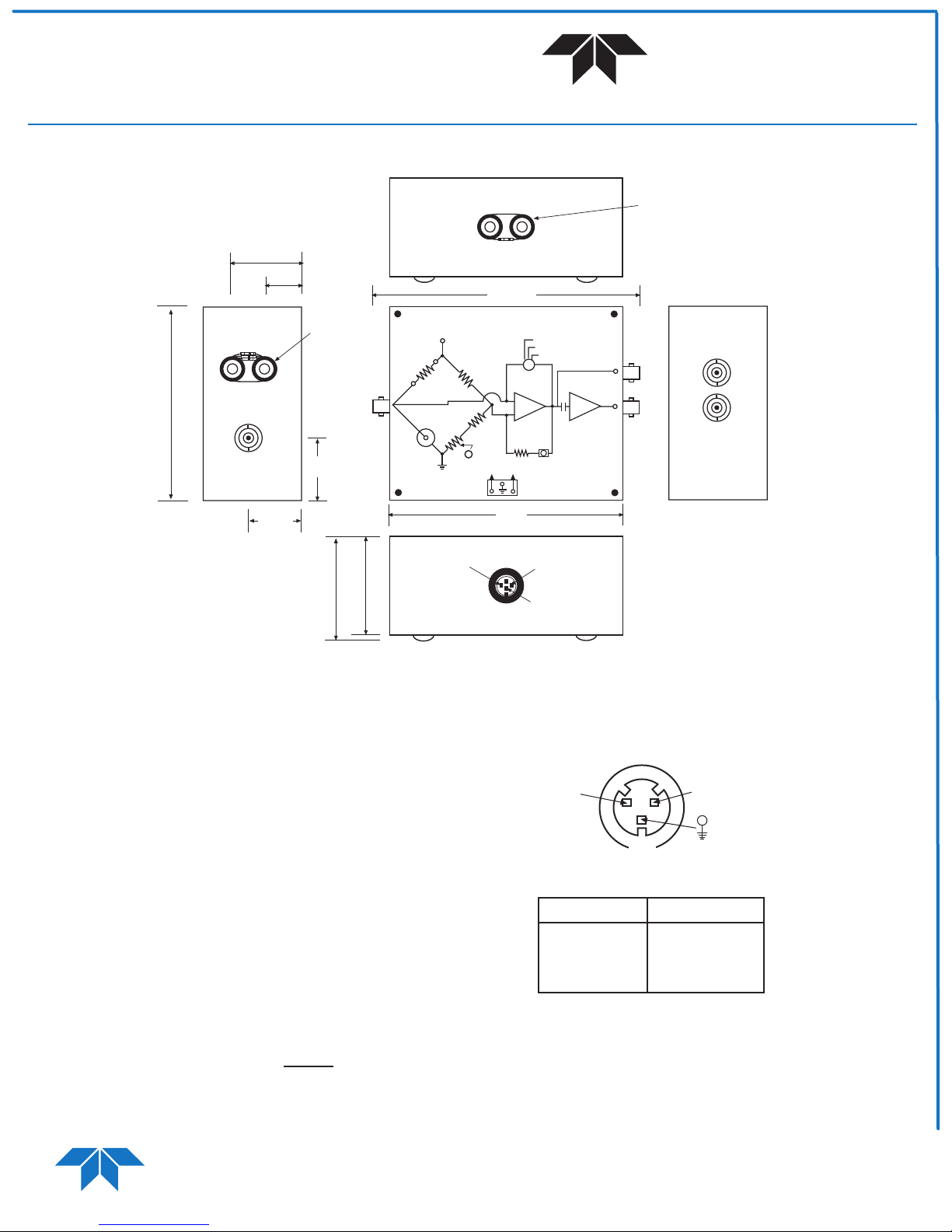
2 1/2"
7/8"
3/8"
R
BIAS
7/8"
R
(BIAS)
INPUT
TELEDYNE
JUDSON TECHNOLOGIES
A Teledyne Technologies Company
PB 3207
R
LIN
4 1/8"
PA-300
SET
R
+15V -15V
GAIN SELECT
HIGH
MED
LOW
-
+
R
LIN
ADJUST
FIRST
STAGE
OUT
SECOND
STAGE
OUT
X10
LIN
+15V
B
BIAS
ADJUST
December 2002
7/8"
nom.
1 3/4"
nom.
1 5/8"
Specifications
Bandwidth: First Stage - DC to 1.0MHz
Second Stage - 200Hz to 100KHz, AC coupled
Gain: First Stage(V/A) - 100(LO), 300(MED), 1000(HI)
Second Stage - x10
Noise Density (NV/� Hz): 1.5
Output Impedance: - 100�
Maximum Output Voltage: ± 10V P-P
Power Requirements: ± 15V DC @ 200mA
Bias Voltage (internally supplied): +15V
Size: 2 1/2" x 4 1/8" x 1 3/4"
Power Connector: 3 pin circular miniature DIN
Description
Teledyne Judson's PA-300 DC-coupled preamplifiers are
designed for operation with photoconductive HgCdTe
detectors. The preamps offer low noise, adjustable gain,
DC offset compensation and a linearizing network.
The PA-300 applies a constant bias voltage V across
B
the detectorto produce a current signal.
V
i
signal
=
� R
B
D
3"
+15
-15
AMP
GND
Power Requirements
The PA-300 comes with a miniature DIN connector and is
connected as follows.
+15V
-15V
Ground
The PA-300 is supplied with a cable where
Wire Power
red +15
black -15
green ground
Because the main power supply also provides the detector
bias, a low-noise power supply is critical. Any fluctuations
in the bias will appear as detector noise. Batteries are
strongly recommended. A well-filtered power supply may
also be used.
TELEDYNE
JUDSON TECHNOLOGIES
A Teledyne Technologies Company
221 COMMERCE DRIVE
MONTGOMERYVILLE, PA 18936-9641
PHONE: 215-368-6901
FAX: 215-362-6107
1/2
www.teledynejudson.com
PA-300
PREAMPLIFIERS
Operating Instructions
TELEDYNE
JUDSON TECHNOLOGIES
A Teledyne Technologies Company
Detector Biasing
When purchased with a J15 Series HgCdTe detector, the
preamplifier is supplied with a bias resistor to provide
optimum bias voltage to the detector.
If the amplifier was purchased without the detector, the
amplifier should be matched to the detector in the
following manner:
1. Remove the linearizing resistor if applicable.
2. The factory installed set resistor is 207 ohms
(nominal) for a 1mm square detector and bias of 1.2VDC.
The value of the set resistor can be determined by using
Table 1.0 or the following formula.
R
= 2210 V
set
When installing R
set
detectors, use the following table to select R
Bias
and R
/ (V
lin
- V
Bias
- 0.7)
Supply
on customer supplied
set
and R
.
lin
Use 1% resistors.
Det. Size Nominal
(PC MCT) V
Bias
R
set
.10 .125 19.0
.25 .30 47
.50 .60 97
1.0 1.2 200
2.0 2.4 450
3.0 3.6 750
4.0 4.3 1100
Table 1.0
The voltage bias set resistor R
should be installed in
set
the amplifier. This is done by removing the top cover
and de-soldering the R
resistor. This resistor is
set
mounted on solder clips for ease of replacement.
The detector bias voltage is set with the bias resistor R
and detector disconnected. Set detector bias voltage to
values indicated on detector data sheet by adjusting
bias pot while monitoring the voltage at the first stage
output BNC.
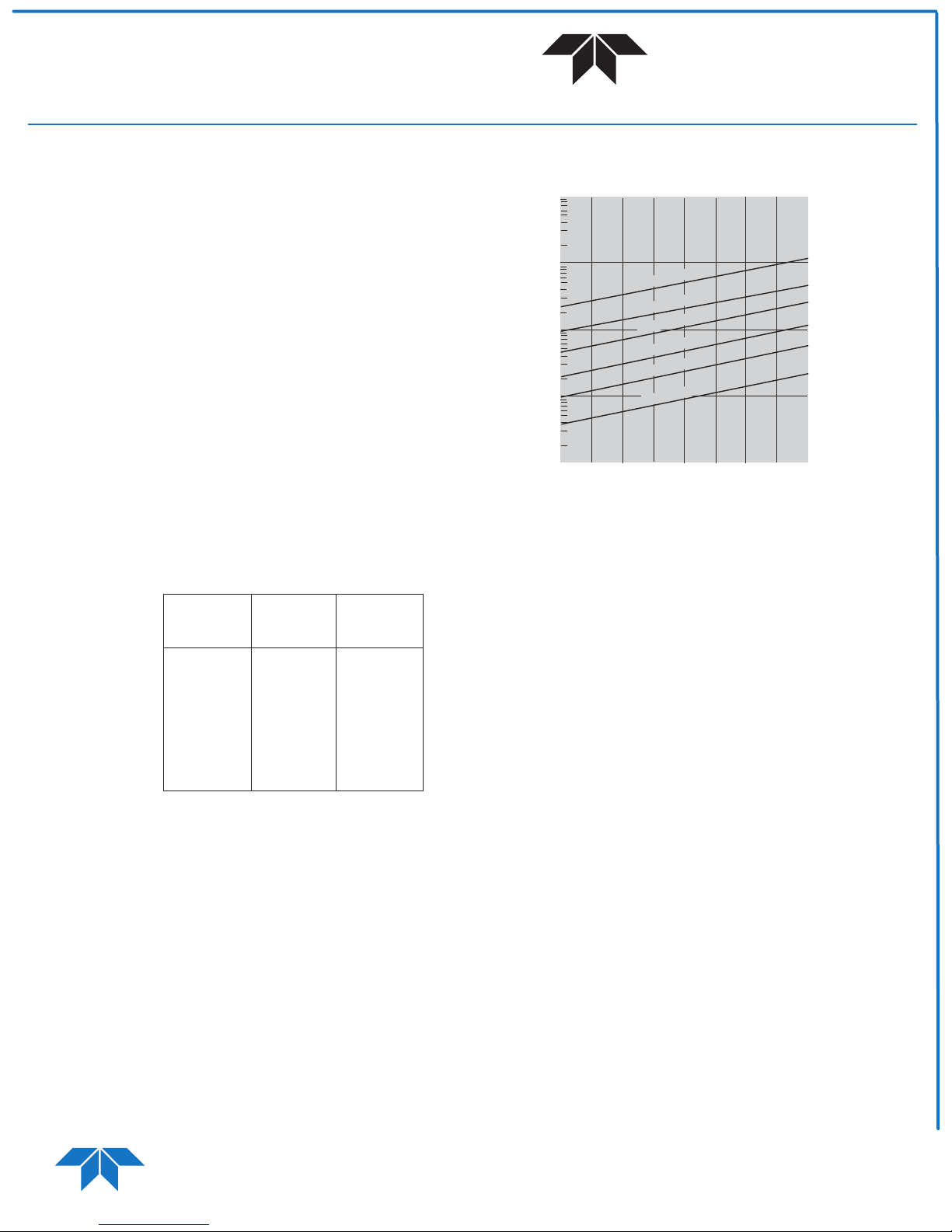
Bias Resistor Selection for HgCdTe Detectors
100K
10K
(� )
1K
Bias Resistor
100
10
20 30 40 50 60 70 80 90 100
Table 2.0
3. The bias resistor (R
.100mm square
.25mm square
.50mm square
1.0mm square
2.0mm square
4.0mm square
Detector Resistance
) is selected to balance the bridge
B
(� )
network and must be selected to provide all of the current
to the detector. The value of RB can be calculated using
the following formula or Table 2.0.
RB = (V
Supply
- V
- 0.7) R
Bias
Detector
/ V
Bias
Choose the closest 1% metal film resistor value for the bias
- V
resistor with a power rating > (V
supply
- 0.7)2/ RB. If
Bias
bias power is over 0.25 watts, use either higher power
resistors or parallel two resistors of double the value.
Connect the bias resistor to the external pin jacks on the
amp. Cool the detector to its operating temperature and
connect it to the amplifier input. Select high gain setting
and verify first stage output voltage < 1V. If greater than
1V, adjust RB closer to calculated values until first stage
output voltage < 1V. Final adjustments in first stage
output offset voltage to 0V can be made by adjusting bias
pot if necessary.
If the detector is used with high optical power levels such
as in an FTIR application, this adjustment should be made
with the unit in the system.
B
Installing the Linearizing Resistor
The optional linearizing resistor should be used as
necessary to bring the spectral response curve baseline
back to a zero level. The value of this resistor required
should be between 2Kohms and 20Kohms. The linearity
adjust potentiometer can be used for fine adjustments.
Information in this document is believed to be reliable. However, no responsibility is assumed for possible inaccuracies or
omission. Specifications are subject to change without notice.
TELEDYNE
JUDSON TECHNOLOGIES
A Teledyne Technologies Company
221 COMMERCE DRIVE
MONTGOMERYVILLE, PA 18936-9641
PHONE: 215-368-6901
FAX: 215-362-6107
2/2
www.teledynejudson.com
 Loading...