

Page 1
Model OT-2 System
OPERATING INSTRUCTIONS
FOR
Model OT-2
Oxygen
Transmitter System
DANGER
HIGHLY TOXIC AND OR FLAMMABLE LIQUIDS OR GASES MAY BE PRESENT IN THIS MONITORING
SYSTEM. PERSONAL PROTECTIVE EQUIPMENT MAY BE REQUIRED WHEN SERVICING THIS SYSTEM.
ONLY AUTHORIZED PERSONNEL SHOULD CONDUCT MAINTENANCE AND/OR SERVICING. BEFORE
CONDUCTING ANY MAINTENANCE OR SERVICING CONSULT WITH AUTHORIZED SUPERVISOR/
MANAGER.
Teledyne Analytical Instruments
P/N: M71265
ECO: #99-0000
10/21/1999
i
Page 2

Model OT-2 System
Copyright © 1999 Teledyne Analytical Instruments
All Rights Reserved. No part of this manual may be reproduced, transmitted,
transcribed, stored in a retrieval system, or translated into any other language or computer
language in whole or in part, in any form or by any means, whether it be electronic,
mechanical, magnetic, optical, manual, or otherwise, without the prior written consent of
Teledyne Analytical Instruments, 16830 Chestnut Street, City of Industry, CA 91749-
1580.
Warranty
This equipment is sold subject to the mutual agreement that it is warranted by us free
from defects of material and of construction, and that our liability shall be limited to
replacing or repairing at our factory (without charge, except for transportation), or at
customer plant at our option, any material or construction in which defects become
apparent within one year from the date of shipment, except in cases where quotations or
acknowledgements provide for a shorter period. Components manufactured by others bear
the warranty of their manufacturer. This warranty does not cover defects caused by wear,
accident, misuse, neglect or repairs other than those performed by Teledyne or an authorized service center. We assume no liability for direct or indirect damages of any kind and
the purchaser by the acceptance of the equipment will assume all liability for any damage
which may result from its use or misuse.
We reserve the right to employ any suitable material in the manufacture of our
apparatus, and to make any alterations in the dimensions, shape or weight of any parts, in
so far as such alterations do not adversely affect our warranty.
Important Notice
This instrument provides measurement readings to its user, and serves as a tool by
which valuable data can be gathered. The information provided by the instrument may
assist the user in eliminating potential hazards caused by his process; however, it is
essential that all personnel involved in the use of the instrument or its interface, with the
process being measured, be properly trained in the process itself, as well as all instrumentation related to it.
The safety of personnel is ultimately the responsibility of those who control process
conditions. While this instrument may be able to provide early warning of imminent
danger, it has no control over process conditions, and it can be misused. In particular, any
alarm or control systems installed must be tested and understood, both as to how they
operate and as to how they can be defeated. Any safeguards required such as locks, labels,
or redundancy, must be provided by the user or specifically requested of Teledyne at the
time the order is placed.
Therefore, the purchaser must be aware of the hazardous process conditions. The
purchaser is responsible for the training of personnel, for providing hazard warning
methods and instrumentation per the appropriate standards, and for ensuring that hazard
warning devices and instrumentation are maintained and operated properly.
Teledyne Analytical Instruments (TAI), the manufacturer of this instrument,
cannot accept responsibility for conditions beyond its knowledge and control. No statement expressed or implied by this document or any information disseminated by the
manufacturer or its agents, is to be construed as a warranty of adequate safety control
under the user’s process conditions.
ii
Teledyne Analytical Instruments
Page 3

Model OT-2 System
Table of Contents
1 Introduction
1.1 Overview........................................................................1-1
1.2 Features..........................................................................1-1
1.3 Typical Applications......................................................1-2
1.4 Operator Interface .......................................................1-3
2 Operational Theory
2.1 Introduction ................................................................... 2-1
2.2 Micro-Fuel Cell Sensor ..................................................2-2
2.2.1 Principles of Operation .......................................... 2-2
2.2.2 Anatomy of a Micro-Fuel Cell............................... 2-2
2.2.3 Electrochemical Reactions...................................2-4
2.2.4 The Effect of Pressure .............................................2-5
2.2.5 Calibration Characteristics ...................................2-6
2.3 Electronics and Signal Processing............................... 2-7
2.4 Oxygen Cell Block Heater............................................2-7
2.5 EMI/RFI Protection.........................................................2-7
2.5 Sample System .............................................................. 2-8
3 Operation
3.1 Installation......................................................................3-1
3.1.1 Unpacking the System .........................................3-1
3.1.2 Mounting the System ........................................... 3-2
3.1.3 System Connections.............................................3-3
3.1.3.1 Gas Connections...................................3-3
3.1.3.2 Electrical Connections.......................... 3-4
3.2 Installing the Micro-Fuel Cell........................................3-6
3.3 Calibration ..................................................................... 3-6
3.3.1 Calibration Gas Connections .............................3-6
3.3.2 Setting the Span....................................................3-8
3.3.3 H2S Scrubber .........................................................3-9
3.3.4 Exhaust/Vent Line.................................................. 3-9
3.4 Testing the System.........................................................3-9
4 Maintenance
4.1 Routine Maintenance ..................................................4-1
4.2 Cell Replacement.........................................................4-1
4.2.1 Cell Warranty.........................................................4-2
4.3 Scrubber Replacement ............................................... 4-3
4.4 Filter Servicing................................................................4-3
Teledyne Analytical Instruments
iii
Page 4

Model OT-2 System
Appendix
Specifications ........................................................................A-1
Recommended Spare Parts List ..........................................A-2
Drawing List ............................................................................ A-2
Material Safety Data Sheet .................................................A-3
The following International Symbols are used throughout the
Instruction Manual for your visual and immediate warnings
and when you have to attend CAUTION while operating the
instrument:
GROUND
Protective Earth
CAUTION, The operator needs to refer to the manual
for further information. Failure to do so may
compromise the safe operation of the equipment.
iv
Teledyne Analytical Instruments
Page 5

Model OT-2 System Introduction 1
Introduction
1.1 Overview
The Teledyne Analytical Instruments Model OT-2 System is
designed to accurately monitor the oxygen content in a wide
variety of gases at the ppm level. The Trace Oxygen Transmitter
is equipped with two oxygen analysis ranges, 0–10 ppm and 0–
100 ppm (0-100 ppm and 0-1000 ppm optional). The OT-2
System is acceptable for operation in Class 1, Division 2, Groups
B, C, and D hazardous environments, when used in conjunction
with a non-insendive power source, such as the Elsag Baily Total
Flow TM System.
The heart of the OT-2 System is Teledyne Analytical Instruments' Micro-Fuel Cell oxygen sensor. This cell is a sealed electrochemical device which translates the amount of oxygen
present in a sample into an electrical current. Since it is sealed,
there is no electrolyte to change or electrodes to clean and
therefore, virtually maintenance free.
The transmitter operates from a 12VDC (nominal) power
source and produces a 1-5VDC voltage output that is directly
and linearly proportional to the oxygen concentration. The
output voltage is used to interface with high input impedance
(>10 Kilo ohms) devices such as recorders, alarms, computers or
other voltage driven devices.
1.2 Features
The following features describe the basic model. The exact
configuration depends on the options selected at the time of
purchase.
• Two analysis ranges: 0–10 ppm and 0-100 ppm (0-100
ppm and 0-1000 ppm optional) user selectable
• High sensitivity (0.5% FS)
• Digital O2 concentration display
Teledyne Analytical Instruments
1-1
Page 6

1 Introduction Model OT-2 System
Accurate (±2% of full scale at constant temperature on
•
100 ppm, or 1000 ppm scale; ±1 ppm on 0–10 ppm scale
at constant temperature)
• Insensitive to flow variations
• Fast response and recovery
• Long life, maintenance-free Micro-Fuel Cell oxygen
sensor
• Unaffected by reducing agents (HC's, CO, SO
, etc.)
2
• Easy to calibrate, no zero gas required
• 12VDC Battery Powered w/ 1-5 VDC Output
• Rugged NEMA 4, bulkhead mounted enclosure
• Stainless Steel sample system (nylon cell holder)
• H
S scrubber
2
• Pressure regulation with gage
• Sample filter
• Flowmeter
• Heated cell holder assembly
1.3 Typical Applications
Although the OT-2 System is designed in conjunction with the
Elsag Baily Total Flow
capable of monitoring oxygen at the ppm level in a variety of
gases. A few typical applications include:
TM
System for natural gas production, it also is
1-2
• Gas gathering and transportation
• Monitoring inert gas blanketing
• Air separation and liquefaction
• Chemical feedstock analysis
• Petrochemical process control
• Heat treating and bright annealing processes
• Quality assurance
• Gas certification
• Welding applications
Teledyne Analytical Instruments
Page 7
Model OT-2 System Introduction 1
1.4 Operator Interface
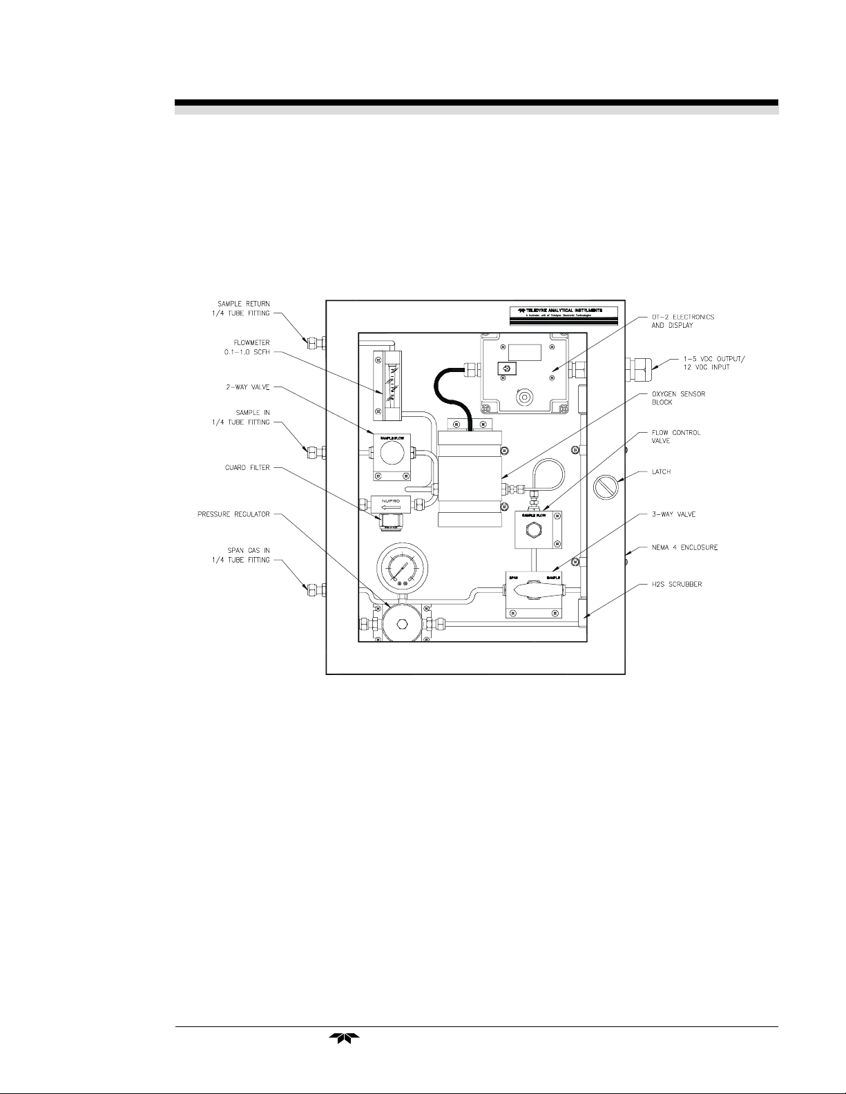
The OT-2 System is housed in a rugged metal NEMA-4 case
with the display visible from the front and the controls accessible
from inside the front door. See Figure 1-1. The front door has a
clear Lexan window for viewing the sample system components
and transmitter display.
Figure 1-1 Front View
Access Door: For access to the Micro-Fuel Cell and transmitter controls, the front door swings open when the slotted latch in
the middle right side of the door is turned counter-clockwise. The
replaceable Micro Fuel Cell is housed in a nylon cell block positioned for easy access.
OT-2 Electronics & Display: The OT-2 meter display is a LCD
device that produces 3.5 decimal, 7-segment numbers that are
legible in daylight. It produces a continuous readout of oxygen
cencentration. Accessing the transmitter electronics requires
unfastening the screws of the transparent front cover of the OT-2
and lifting the cover off.
Flowmeter: Monitors the flow of gas past the sensor. Readout
is 0.1-1 standard cubic feet per hour (scfh).
H
S Scrubber: The H2S scrubber prevents H2S gas from affect-
2
ing the oxygen sensor.
Teledyne Analytical Instruments
1-3
Page 8

1 Introduction Model OT-2 System
1-4
Teledyne Analytical Instruments
Page 9

Model OT-2 System Operational Theory 2
Operational Theory
2.1 Introduction
The OT-2 System is composed of three subsystems:
1. Micro-Fuel Cell Sensor
2. Electronic Signal Processing, Display and Control
3. Sample System
The Micro-Fuel Cell is an electrochemical galvanic device
that translates the amount of oxygen present in the sample into an
electrical output.
The electronic signal processing, display and control subsystem provides oxygen concentration information both visually
and electronically.
The sample system accepts the sample gas and removes the
S in the sample prior to introduction to the sensor.
H
2
Teledyne Analytical Instruments
2-1
Page 10
2 Operational Theory Model OT-2 System
2.2 Micro-Fuel Cell Sensor
2.2.1 Principles of Operation
The oxygen sensor used in the Model OT-2 System is a Microfuel Cell designed and manufactured by Analytical Instruments. It
is a sealed plastic disposable electrochemical transducer.
The key components of the Micro-Fuel Cell are a diffusion
barrier in the form of a thin membrane, a cathode, an anode, and
an electrolyte in which they are immersed.
Oxygen from the sample gas diffuses through the thin membrane and is reduced at the cathode. As a result, an electrical
current is produced that is proportional to the concentration of
oxygen in the sample gas.
The choice of electrolyte, and hence the sensor type, depends on the exact constituents of the sample gas. For sample
gases that contain a high concentration of CO
acid electrolyte will be the more optimal choice.
, for example, an
2
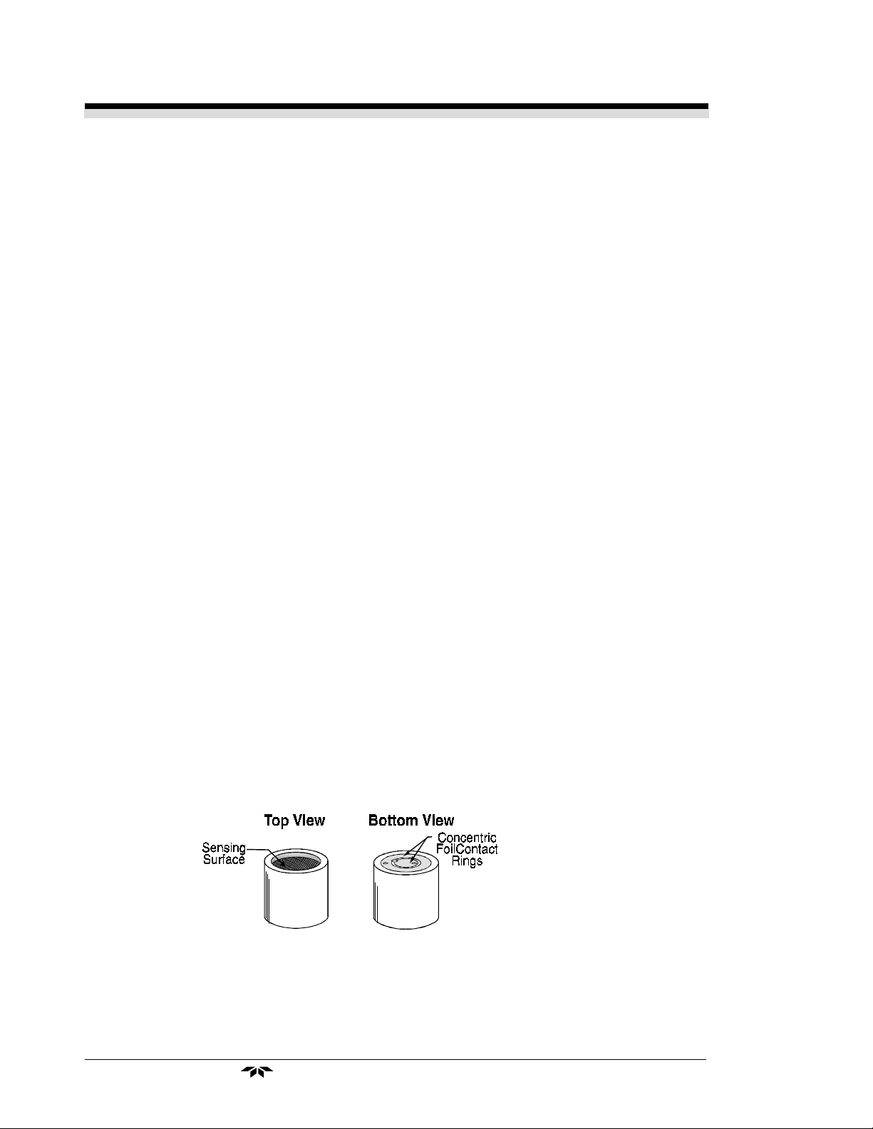
2.2.2 Anatomy of a Micro-Fuel Cell
The Micro-fuel Cell is approximately 1¼ inches in diameter.
The cell body is made of an inert plastic that is compatible with a
wide variety of sample streams. Oxygen from the sample gas
diffuses through a thin membrane located at one end of the
sensor. The other end of the cell is a contact plate consisting of
two concentric foil rings. The rings mate with spring-loaded contacts in the sensor block assembly and provide the electrical
connection to the rest of the analyzer. Figure 2-1 illustrates the
external features.
Figure 2-1: Micro-Fuel Cell
2-2
Teledyne Analytical Instruments
Page 11
Model OT-2 System Operational Theory 2
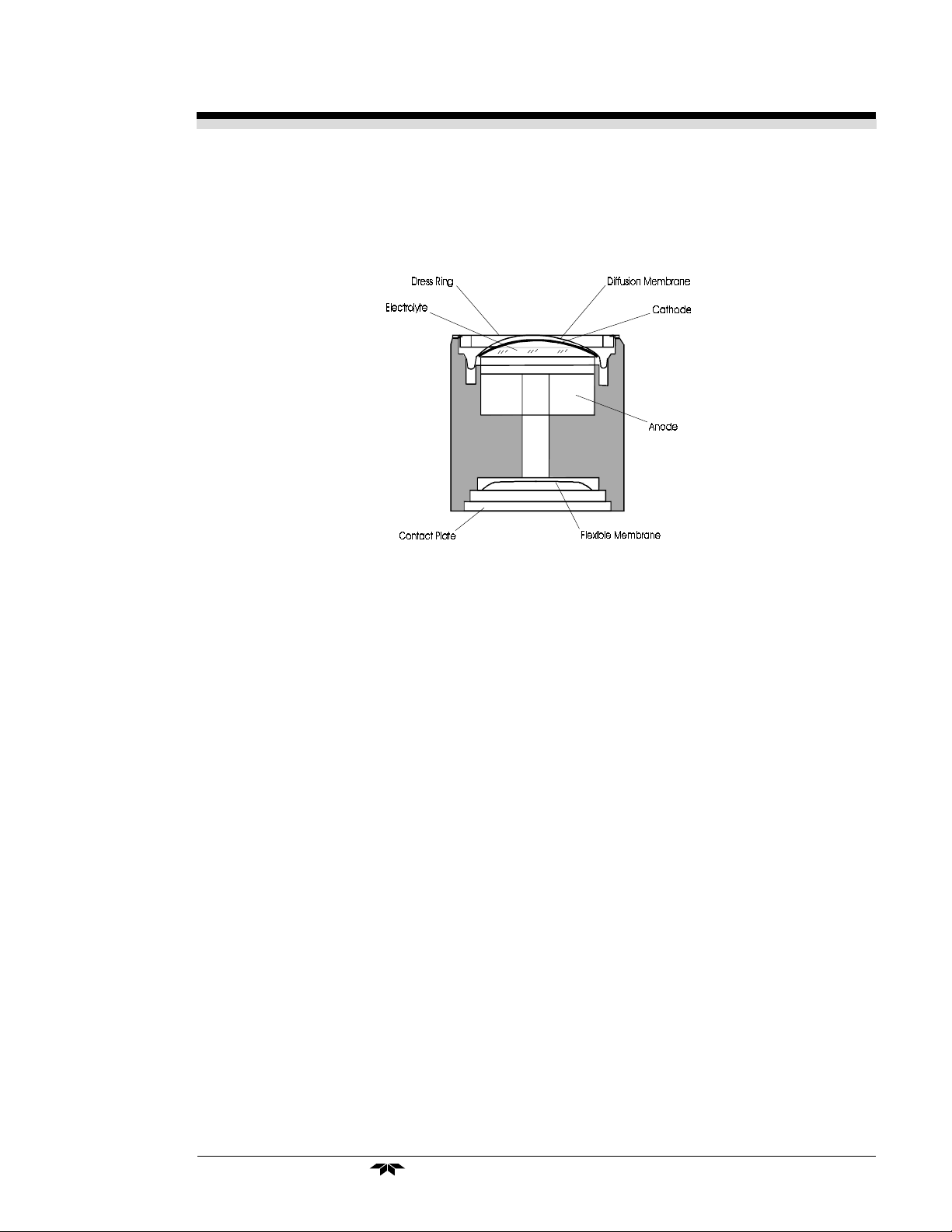
Refer to Figure 2-2,
illustrates the following internal description.
Cross Section of a Micro-Fuel Cell
Figure 2-2. Cross Section of a Micro-Fuel Cell (not to scale)
, which
At the top end of the cell is a diffusion membrane of Teflon.
Beneath the diffusion membrane lies the oxygen sensing element—the cathode.
The anode provides the electrical driving force for the reduction of oxygen at the cathode.
At the rear of the cell, just below the anode structure, is a
flexible membrane designed to accommodate the internal volume changes that occur throughout the life of the cell. This flexibility assures that the sensing membrane remains in its proper position, keeping the electrical output constant.
The entire space between the diffusion membrane, above the
cathode, and the flexible rear membrane, beneath the anode, is
filled with electrolyte. Cathode and anode are submerged in this
common pool. They each have a conductor connecting them to
one of the external contact rings on the contact plate, which is on
the bottom of the cell.
Teledyne Analytical Instruments
2-3
Page 12

2 Operational Theory Model OT-2 System
2.2.3 Electrochemical Reactions
The sample gas diffuses through the Teflon membrane. For a
sensor that employs KOH as electrolyte, oxygen in the sample gas
is reduced on the surface of the cathode according to the following HALF REACTION:
O
+ 2H2O + 4e– ® 4OH
2
(Four electrons combine with one oxygen molecule—in the
presence of water from the electrolyte—to produce four hydroxyl
ions.)
When the oxygen is reduced at the cathode, lead is simultaneously oxidized at the anode by the following HALF REACTION:
Pb + 2OH
–
® Pb+2 + H2O + 2e
(Two electrons are transferred for each atom of lead that is
oxidized. Therefore it takes two of the above anode reactions to
balance one cathode reaction and transfer four electrons.)
–
–
(cathode)
(anode)
The electrons released at the surface of the anode flow to the
cathode surface when an external electrical path is provided. The
current is proportional to the amount of oxygen reaching the
cathode. It is measured and used to determine the oxygen concentration in the gas mixture.
The overall reaction for the fuel cell is the SUM of the half
reactions above, or:
2Pb + O
® 2PbO
2
(These reactions will be the dominant sensor current component as long as no gaseous components capable of oxidizing
lead—such as iodine, bromine, chlorine and fluorine—are present
in the sample.)
In the absence of oxygen, the output of the sensor is approximately zero.
Warning:The sensor used in the Model OT-2 System uses electro-
lytes which contain substances that are harmful if
touched, swallowed, or inhaled. Avoid contact with
ANY fluid or powder in or around the unit. What may
appear to be plain water could contain one of these
harmful substances. In case of eye contact, immediately flush eyes with water for at least 15 minutes. Call
physician. (See Appendix - Material Safety Data Sheet
(MSDS)).
2-4
Teledyne Analytical Instruments
Page 13

Model OT-2 System Operational Theory 2
2.2.4 The Effect of Pressure
The Micro-Fuel Cell responds to the partial pressure of oxygen
present inside the cell holder.
By design, the total gas pressure inside the cell holder is kept
approximately the same as the atmospheric pressure. As the
atmospheric pressure changes, the partial pressure of oxygen in
the cell holder will change accordingly.
The impact due to changes in atmospheric pressure is usually
limited to less than 3% of reading.
Teledyne Analytical Instruments
2-5
Page 14

2 Operational Theory Model OT-2 System
2.2.5 Calibration Characteristics
Given that the total pressure of the sample gas on the surface
of the Micro-Fuel Cell input is constant, a convenient characteristic of the cell is that the current produced in an external circuit is
directly proportional to the rate at which oxygen molecules reach
the cathode, and this rate is directly proportional to the concentration of oxygen in the gaseous mixture. In other words it has a
linear characteristic curve, as shown in Figure 2-3. Measuring
circuits do not have to compensate for nonlinearities.
In addition, since the sensor output is approximately zero in the
absence of oxygen, the characteristic curve has close to an
absolute zero (within ± 1 ppm oxygen or better, depending on the
sensor type and model). In practical application, zeroing may still
be used to compensate for the combined zero offsets of the cell
and the electronics.
2-6
Figure 2-3. Characteristic Input/Output Curve for a Micro-Fuel Cell
Teledyne Analytical Instruments
Page 15

Model OT-2 System Operational Theory 2
2.3 Electronics and Signal Processing
The OT-2 circuitry consists of three stages: an input stage, a
temperature compensation/gain stage and an output stage.
The input stage consists of a current to voltage converter
producing a voltage signal that is proportional to the oxygen
concentration as detected by the sensor.
The temperature compensation stage contains circuitry that
compensates for the temperature effects on the output current of
the O
the sensor temperature.
ohms corresponding to 0-100% of full scale of the selected range.
range of 9-16 VDC. It is recommended that the output cable be
no longer than 10 feet. A shielded cable should be used whenever possible to minimize electrical noise pickup.
cell. A thermistor mounted in the sensor assembly monitors
2
The output stage provides a 1-5 volt signal into a load >10K
The transmitter circuitry operates with a power supply voltage
2.4 Oxygen Cell Block Heater
The OT-2 system is equipped with an insulated and electrically
heated cell block. The heater is switched on when the enclosure
temperature dips below 1oC. The 3 watt heater is controlled by the
electronic control unit.
Note: The cell block insulation must be in place for the
heater system to be effective.
2.5 EMI/RFI Protection
The OT-2 System is well shielded from EMI/RFI. The transmitter
electronics are mounted within a grounded metallic enclosure,
and the electronics is housed within the main system enclosure. For
optimal transmitter performance, the main system enclosure
should be well grounded.
Teledyne Analytical Instruments
2-7
Page 16

2 Operational Theory Model OT-2 System
2.6 Sample System
The system consists of a shut off valve, particulate filter, pressure regulator, scrubber, calibration selector valve, flow control
valve, O
inch tube fittings for sample inlet and outlet connections at the
side of the enclosure.
leading to the formation of lead sulphide with the anode material.
To eliminate the deleterious effect of H
ber is filled with Purafil
transmitter and a sample flow meter and incorporates ¼
2
S from the sample gas can diffuse into the Micro-Fuel Cell
H
2
S on the sensor, the scrub-
®
.
2
Sample Flow Description
: (See Figure 2-4)
1. The sample enters the transmitter system via the shut off valve
at 6-40 psig and passes through the filter where particulates, to
90 microns, are trapped.
2. A pressure regulator, which has been preset at the factory to
approximately 5 psig ensures a constant gas flow to the sensor.
3. After the pressure regulator, the sample gas passes through the
scrubber to the calibration selector valve.
4. When the sample has been selected, it flows through the flow
control valve to the O
sensor.
2
5. Finally, the sample flows through the flow meter and exits the
system through the vent line to a safe area at atmospheric
pressure.
Note: The flow control valve should be adjusted until the
flow meter indicates a flow rate of 0.4 scfh.
SAMPLE IN
6-40 PSIG
2-8
FILTER
SCRUBBER
Figure 2-4 Flow Diagram
Teledyne Analytical Instruments
H2S
SPAN GAS IN
O2 XMTR
0-10 PPM
FLOWMETER
.1-1.0 SCF H
VENT TO
ATMOSPHERE
PRESSU RE
(SAFE AREA)
Page 17

Model OT-2 System Operational Theory 2
Figure 2-5 Piping Layout
Figure 2-5 is the Piping Layout of the sampling system. In the
standard instrument, calibration gases (zero and span) are connected directly to the Span Gas In port by teeing to the port with
appropriate valves. The sample gas is connected to the Sample
Gas In port in the same manner as the Span Gas.
Teledyne Analytical Instruments
2-9
Page 18

2 Operational Theory Model OT-2 System
2-10
Teledyne Analytical Instruments
Page 19

Model OT-2 System Operation 3
Operation
Operation of the Model OT-2 System involves installing the unit,
making appropriate sample gas connections, and calibration.
3.1 Installation
WARNING: Safe operation of the system requires the user to
properly ground the system, install the wiring and
power the transmitter.
It is the user's responsibility to determine and install, should a safety barrier be required.
Installation of the Model OT-2 System includes:
1. Unpacking
2. Mounting
3. Gas connections
4. Electrical connections
5. Installing the Micro-Fuel Cell
6. Testing the system.
3.1.1 Unpacking the Analyzer
Carefully unpack the analyzer and inspect it for damage.
Immediately report any damage to the shipping agent.
Teledyne Analytical Instruments
3-1
Page 20

3 Operation Model OT-2 System
3.1.2 Mounting the Analyzer
The OT-2 System is designed for bulkhead mounting. Figure 3-1
is an illustration of the OT-2 System and mounting hole dimensions.
There are four mounting holes—one in each of the inside corners
of the rigid enclosure.
3-2
Figure 3-1 Mounting Details
Teledyne Analytical Instruments
Page 21

Model OT-2 System Operation 3
All operator controls are located inside the system enclosure,
which is hinged on the left edge and provides easy access to the
transmitter, sensor and cell block inside the instrument. The main
enclosure door will swing open when the slotted latch at the right
center of the door is turned counter-clockwise. Allow clearance
for the door to open in a 90-degree arc at a radius of 16 inches.
See Figure 3-1.
3.1.3 System Connections
Figure 3-2 shows the Model OT-2 System. There are ports for
gas inlet and outlet, power and analog concentration output.
Figure 3-2 Front View of OT-2 System
3.1.3.1 Gas Connections
The unit is manufactured with
installations.
Teledyne Analytical Instruments
1
/4 inch tube fittings for system
3-3
Page 22

3 Operation Model OT-2 System
To connect gas lines to the Model OT-2 System:
1. Insert the tube into the tube fitting, and finger-tighten the
nut until the tubing cannot be rotated freely, by hand, in
the fitting. (This may require an additional 1/8 turn
beyond finger-tight.)
2. Hold the fitting body steady with a wrench, and with
another wrench rotate the nut another 1-1/4 turns.
All gas connections, Sample In, Sample Return and Span Gas
In are made at the connectors located on the left side of the
system enclosure as shown in Figure 3-2.
SAMPLE IN: The gas connection for the sample is made at the
SAMPLE IN connector.
The internal gas pressure regulator is factory preset to approximately 3 psig which will keep the system flowmeter reading in an
acceptable range (0.1-1 scfh). The sample in pressure can be 6-40
psig.
SAMPLE RETURN: Exhaust connections must be consistent with
the hazard level of the constituent gases. Check Local, State, and
Federal laws, and ensure that the exhaust stream vents to an
appropriately controlled area if required.
SPAN GAS IN: This is the port for inputting span gas and zero
gas. The span gas source should be regulated at 3 psig.
3.1.3.2 Electrical Connections
All electrical connections for the OT-2 System are made on a
terminal blocks in the transmitter box located on the inside of the
system enclosure, see Figure 3-3.
1. To access the terminal block remove the four screws
securing the transmitter box cover and remove it.
2. Connect the 4 wires and shield to the terminal block as
shown in Figure 3-4.
3. Replace the cover and screws.
For safe connections, ensure that no uninsulated wire extends
outside of the connectors they are attached to. Stripped wire
ends must insert completely into terminal blocks. No uninsulated
wiring should be able to come in contact with fingers, tools or
clothing during normal operation.
3-4
Teledyne Analytical Instruments
Page 23

Model OT-2 System Operation 3
(4 p
)
Transmitter Cover
Screws
laces
Display
To Sensor
Span
Electrical
Connections
Figure 3-3 Front View of Transmitter
System Power Requirements:
The Model OT-2 System requires a 12 VDC (nominal), reverse
polarity protected power source.
Observe good wiring practices. For hazardous area
applications, the Model OT-2 System must be powered by a source that is consistent with intrinsically
safe operation.
Analog Outputs:
1-5 VDC: Voltage increases linearly with increasing oxygen,
from 1 VDC at 0 ppm to 5 VDC at full scale ppm.
Figure 3-4: Transmitter Electrical Connections
Teledyne Analytical Instruments
3-5
Page 24

3 Operation Model OT-2 System
3.2 Installing the Micro-Fuel Cell
The Micro-Fuel Cell is not installed in the cell block when the
instrument is shipped. Install it before the analyzer is placed in
service.
When the micro-Fuel Cell needs to be installed or replaced,
follow the procedures in chapter 5,
and installing cells.
Recommendation: During installation, minimize the time the
sensor is exposed to atmospheric oxygen, i.e. the time between
removal of the sensor from the sealed bag to installation into the
cell holder.
Maintenance,
for removing
3.3 Calibration
The calibration process consists of:
• Connecting span gas to Span In Port
• Setting the span
Setting the span of the transmitter requires adjustment of the
potentiometer located on the transmitter box.
The sensor will respond to changes in oxygen concentration
immediately after installation. For maximum performance (accuracy and sensitivity) TET/AI recommends that the sensor be purged
with a zero (0% oxygen) gas for about 24 hours after the sensor is
installed and then calibrate with span gas with a value of approx.
80-100% of the analytical range of interest. The following sections
describe the calibration procedure.
3.3.1 Calibration Gas Connections
Prior to installation of the O
taining less than 1 ppm O2, should be connected to the system
and be ready to purge the O2 cell. To facilitate spanning the zero
and span gas source can be connected to a common manifold
via a three way valve. This manifold then connects directly to the
"Span Gas In" port on the system (Fig. 3-5).
cell, a zero gas (purge gas) con-
2
It is important that the
operator bleeds any trapped air in the tubing prior to installation
of the sensor to minimize the amount of atmospheric oxygen
introduced into the system.
NOTE: In order to minimize the time required to purge the cell
after exposure to air, limit the time the cell is exposed to
air to 1 minute or less, if possible.
3-6
Teledyne Analytical Instruments
Page 25

Model OT-2 System Operation 3
The span gas cylinder must be equipped with a pressure
regulator with a metallic diaphragm. The regulator should be set to
approximately 3-5 psig. Rotate the selector valve (a) to the span
position and observe the flow meter (b) which should indicate a
flow of about 0.4 scfh. For calibration purposes the flow can be
increased to as much as 1 scfh in order to reduce the time required to stabilize.
Allow the span gas to pass through the O
reading has stabilized (approx. 10 min.). The O
then be adjusted (see instructions elsewhere in this section) to
match the analyzed content of the span gas. When the calibration
is complete, return the selector valve (a) to the sample position
and readjust the flow valve (c), (if necessary) so that flow meter
(b) reads 0.4 scfh.
sensor until the
2
transmitter can
2
Figure 3-5 Sample System Component Locations
Teledyne Analytical Instruments
3-7
Page 26

3 Operation Model OT-2 System
NOTE: This procedure is more critical on the 0-10 ppm range and
less critical on the 0-100 or 0-1000 ppm range.
3.3.2 Setting the Span Pot
1. Switch the system from zero gas to span gas and allow
time for stabilization.
Display
Span
Span Pot
Figure 3-6: Span Pot Location
NOTE: The span gas should have an O2 concentration of 80% -
100% of full scale. For example, if the range is set at 0-100
ppm, the span gas should be a certified grade gas of
about 90 ppm O2 in N2 or Argon.
2. If 90 ppm gas is used, adjust the span pot (Figure 3-6)
to read 90.0 ppm on the LCD display. The output to
the Elsag Baily Total Flow TM computer will have a
signal of 4.6VDC (into a >10K ohm load).
3-8
The formula for this is:
Span Gas % F.S. x 4
100
Teledyne Analytical Instruments
+=
Output in VDC
1
Page 27

Model OT-2 System Operation 3
3.3.3 H2S Scrubber
The life expectancy of the stainless steel H2S scrubber, included in this system, is determined by the amount of H2S passing
through it.
With the maximum concentration of 200 PPM H
rate of 0.2 scfh the expected scrubber life will be over 6 months
with Purifil® and over 11 months with Purifil® II.
This scrubber life expectancy increases with lower H2S concentration or gas sample flow rates. It is recommended that the
flow rate be set
should be increased only if a faster system response time is desired.
It is suggested that a spare scrubber be kept on hand and
replaced every 6 months. When the scrubber needs to be replaced, follow the procedure in section 4,
ber Replacement".
WARNING: IF SCRUBBER IS NOT PROPERLY MAINTAINED THE
no higher than 0.4 scfh initially. The flow rate
Maintenance
O
SENSOR LIFE WILL BE SHORTENED.
2
S and a flow
2
, "Scrub-
3.3.4 Exhaust/Vent Line (Sample Return)
It is recommended that a long vent line (approx. 4 ft.) be
installed to the "Sample Return" connector at the side of the system enclosure. The extended vent line will minimize back diffusion
from the atmosphere back to the sensor. The minimum recommended tubing diameter is 1/4" to minimize back pressure.
3.4 Testing the System
Before connecting the instrument into the power source:
• Check the integrity and accuracy of the gas
connections. Make sure there are no leaks.
• Check the integrity and accuracy of the electrical
connections. Make sure there are no exposed
conductors.
• Check that inlet sample pressure is within the
acceptable range (see section 3.3.1).
• Power up the system, and test it.
Teledyne Analytical Instruments
3-9
Page 28

3 Operation Model OT-2 System
3-10
Teledyne Analytical Instruments
Page 29

Model OT-2 System Maintenance 4
Maintenance
4.1 Routine Maintenance
Aside from normal cleaning and checking for leaks at the gas
connections, routine maintenance includes servicing the filter, the
scrubber, installing replacement Micro-Fuel cells and recalibration.
For recalibration, see section 3.3
Calibration
.
4.2 Cell Replacement
The Micro-Fuel Cell is a sealed electrochemical transducer
with no electrolyte to change or electrodes to clean. When the
cell reaches the end of its useful life, it is replaced. The spent fuel
cell should be discarded according to local regulations.
The characteristics of the Micro-Fuel Cell are similar to those
of a mercury battery in that both provide an almost constant
output (when the sensor is exposed to a constant level of oxygen)
throughout their useful life, and then fall off sharply towards zero at
the end. Cell failure, in the Model OT-2 System, will probably be
indicated by the inability to properly span calibrate the transmitter,
or excessively long response time to changes in oxygen concentration.
To ensure availability, TAI recommends that a spare cell be
purchased shortly after the instrument is placed in service, and
each time the cell is replaced.
The spare cell should be carefully stored in a cool, and near
constant temperature, area if possible.
NOTE: Do not disturb the integrity of the cell package until the
cell is to actually be used. If the cell package is punctured
and has been exposed to atmospheric air over an extended period, the sensor may not function properly.
Power must be removed from the OT-2 prior to removing or
installing the sensor.
Teledyne Analytical Instruments
4-1
Page 30

4 Maintenance4 Maintenance
4 Maintenance Model OT-2 System
4 Maintenance4 Maintenance
To replace the cell: Figure 4-1
1. Open the enclosure door.
2. Undo the velcro straps.
3. Remove the insulation.
4. The cell block is located in the center of the unit.
Unscrew the cap on the bottom of the cell block. The
B-2C sensor should drop down once the cap is
removed.
INSULATION
B-2C
SENSOR
CAP
Figure 4-1 Cell Block
NOTE: Before the cell is removed from its package, a zero gas
with low ppm oxygen flowing at a relative high rate
through the cell block can lessen the time it will take the
newly installed cell to drop to a zero reading.
3. Remove the new cell from its package, and carefully
remove the shorting clip.
WARNING: The sensor used in the Model OT-2 System uses
electrolytes which may contain substances that are
harmful if touched, swallowed, or inhaled. Avoid
contact with ANY fluid or powder in or around the
unit. What may appear to be plain water could
contain one of these toxic substances. In case of
eye contact, immediately flush eyes with water for
at least 15 minutes. Call physician. {See Appendix Material Safety Data Sheet (MSDS)}.
4-2
Teledyne Analytical Instruments
Page 31

Model OT-2 System Maintenance 4
4. Place the new cell on the cap with the sensing surface
face down and the gold contact rings up.
5. Position the cell and cap so that the cell is inside the cell
block. Press up on the cap and rotate. Tighten the cap
screws.
4.2.1 Cell Warranty
The cell warranty is sensor specific. Please contact Teledyne
Electronic Technologies/ Analytical Instruments on explicit warranty on sensors.
NOTE: Evidence of damage due to tampering or mishandling will
render the cell warranty null and void.
4.3 Scrubber Replacement
To ensure proper operation of the OT-2 System, it is recommended to replace the scrubber every 6 months or more frequently if the sensor is reaching end of life prematurely.
It is important that the replacement of the scrubber be completed within one hour of it's removal to prevent back diffusion of
oxygen from the atmosphere to the sensor.
During scrubber replacement, it is recommended that the 3way valve is switched to "Span Gas". This will minimize the system
recovery time.
NOTE: If the sensor is exposed to air through back diffusion, from
the atmosphere it may cause the sensor to re-stabilize
slowly.
4.4 Filter Servicing
To ensure the proper performance and sample flow, it is
recommended that the sample filter be inspected when the cell is
replaced. The filter requires both a 1" and a 11/16" open end
wrench to remove the filter bowl. Turn off the sample flow valve
prior to servicing filter. The filter should be cleaned or replaced as
required.
Teledyne Analytical Instruments
4-3
Page 32

4 Maintenance4 Maintenance
4 Maintenance Model OT-2 System
4 Maintenance4 Maintenance
4-4
Teledyne Analytical Instruments
Page 33

Model OT-2 System Appendix
Appendix
Specifications:
System Enclosure: NEMA 4 Rated, bulkhead mounted
Power Requirements: 9-16 VDC and 16-275mA.
Ranges: 0–10ppm and 0–100ppm Oxygen
or 0-100 ppm and 0-1000 ppm O2.
Accuracy: ± 2% of full scale at constant temperature and
pressure (temperature and pressure of calibration), except ± 1ppm on 0–10ppm range.
± 5% of full scale over operating temperature
range (once thermal equilibrium has been
reached), except ± 1ppm on 0–10ppm range.
Response Time (90%): Sensor Response Time = 61 seconds @ 77°F
(25°C).
Overall system response time is flow rate
dependent.
Operating Temperature: 5-113°F (-15–45°C)
Stability: ± 1% in 24 hours (at constant temperature)
Reproducibility: ± 1% of full scale at constant temperature
Sensor Type: Micro-Fuel Cell class B2C
Optional (application dependent): Micro-Fuel
Cell class A2C if CO2 concentration consistently exceeds 1000 ppm.
Signal Output: 1-5 VDC
Teledyne Analytical Instruments
A-1
Page 34

AppendixAppendix
Appendix Model OT-2 System
AppendixAppendix
Recommended Spare Parts List
Qty. Part Number Description
1 C71345A & C71345B Cell Block Insulation Set
1 C70976B PC Board — 1-5V Transmitter (0-100/0-1000 ppm)
1 C70976A PC Board — 1-5V Transmitter (0-10/0-100 ppm)
1 B71343 Scrubber Assembly (complete)
1 P396 Scrubber Material
1 C6689-B2C Micro-Fuel Cell B2C Class
1 C6689-A2C Micro-Fuel Cell A2C Class
1 F688 Filter
1 H517 Heater
1 C71272 Cell Holder Assembly
A minimum charge is applicable to spare parts orders.
NOTE: Orders for replacement parts should include the part number (if available ) and the
model and serial number of the instrument for which the parts are intended.
Orders should be sent to:
Teledyne Analytical Instruments
16830 Chestnut Street
City of Industry, CA 91749-1580
Phone (626) 934-1500, Fax (626) 961-2538
TWX (910) 584-1887 TDYANLY COID
Web: www.teledyne-ai.com
or your local representative
Drawing List
A-2
C71020 Outline Diagram
B71018 Interconnection Diagram
D70975 Schematic — 1-5V Transmitter
B71019 Piping Diagram
Teledyne Analytical Instruments
Page 35

Model OT-2 System Appendix
Material Safety Data SheetMaterial Safety Data Sheet
Material Safety Data Sheet
Material Safety Data SheetMaterial Safety Data Sheet
Section I – Product Identification
Product Name: Micro-Fuel Cells
Mini-Micro-Fuel Cells, all classes
Super Cells, all classes except T–5F
Electrochemical Oxygen Sensors, all classes.
Manufacturer: Teledyne Analytical Instruments
Address: 16830 Chestnut Street, City of Industry, CA
91749
Phone: (626) 934-1500
Date Prepared or Last Revised: 08/08/91
Emergency Phone Number: (626) 934-1500
Section II – Physical and Chemical Data
Chemical and Common Potassium Hydoxide (KOH), 15% (w/v)
Name s: Lead (Pb), pure
CAS Number: KOH 1310–58–3
Pb 7439–92–1
KOH (15%) Pb (pure)
Melting Point/Range: –10 to 0 °C 328 °C
Boiling Point/Range: 100 to 115 °C 1744 °C
Specific Gravity: 1.09 @ 20 °C 11.34
pH: >14 N/A
Solubility in Water: Completely soluble Insoluble
Percent Volatiles by Volume: None N/A
Appearance and Odor: Colorless, odorless solution Grey metal,
odorless
Teledyne Analytical Instruments
A-3
Page 36

AppendixAppendix
Appendix Model OT-2 System
AppendixAppendix
Section III – Physical Hazards
Potential for fire and explosion: The electrolyte in the Micro-Fuel Cells is
not flammable. There are no fire or explosion hazards associated with Micro-Fuel Cells.
Potential for reactivity: The sensors are stable under normal conditions of
use. Avoid contact between the sensor electrolyte and strong acids.
Section IV – Health Hazard Data
Primary route of entry: Ingestion, eye/skin contact
Exposure limits: OSHA PEL: .05 mg./cu.m. (Pb)
ACGIH TLV: 2 mg./cu.m. (KOH)
Effects of overexposure
Ingestion: The electrolyte could be harmful or fatal if
swallowed.
Oral LD50 (RAT) = 3650 mg./kg
Eye: The electrolyte is corrosive; eye contact could
result in permanent loss of vision.
Dermal: The electrolyte is corrosive; skin contact could
result in a chemical burn.
Inhalation: Liquid inhalation is unlikely.
Signs/symptoms of exposure: Contact with skin or eyes will cause a burning
sensation and/or feel soapy or slippery to
touch.
Medical conditions
aggravated by exposure: None
Carcinogenicity: NTP Annual Report on Carcinogens: Not listed
LARC Monographs: Not listed
OSHA: Not listed
Other health hazards: Lead is listed as a chemical known to the State
of California to cause birth defects or other reproductive harm.
A-4
Teledyne Analytical Instruments
Page 37

Model OT-2 System Appendix
Section V – Emergency and First Aid Procedures
Eye Contact: Flush eyes with water for at least 15 minutes and get immedi-
ate medical attention.
Skin Contact: Wash affected area with plenty of water and remove con-
taminated clothing. If burning persists, seek medical attention.
Ingestion: Give plenty of cold water. Do not induce vomiting. Seek
medical attention. Do not administer liquids to an unconscious person.
Inhalation: Liquid inhalation is unlikely.
Section VI – Handling Information
NOTE: The oxygen sensors are sealed, and under normal circumstances,
the contents of the sensors do not present a health hazard. The
following information is given as a guide in the event that a cell
leaks.
Protective clothing: Rubber gloves, chemical splash goggles.
Cleanup procedures: Wipe down the area several times with a wet paper
towel. Use a fresh towel each time.
Protective measures
during cell replacement: Before opening the bag containing the sensor
cell, check the sensor cell for leakage. If the sensor
cell leaks, do not open the bag. If there is liquid
around the cell while in the instrument, put on gloves
and eye protection before removing the cell.
Disposal: Should be in accordance with all applicable state,
local and federal regulations.
NOTE: The above information is derived from the MSDS provided by the
manufacturer. The information is believed to be correct but does not
purport to be all inclusive and shall be used only as a guide.
Teledyne Analytical Instruments shall not be held liable for any
damage resulting from handling or from contact with the above
product.
Teledyne Analytical Instruments
A-5
Page 38

AppendixAppendix
Appendix Model OT-2 System
AppendixAppendix
A-6
Teledyne Analytical Instruments
 Loading...