

Specifications
OE425/525
OE455/555
Wavelength Range
500–870 nm /
460–870 nm (0.1 V/mW)
950–1630 nm /
800–1630 nm (0.1 V/mW)
Conversion Gain
0.5 V/mW
1.1 V/mW
Bandwidth
4.5 GHz (6 GHz optical)
3.5 GHz (4.5 GHz optical)
Equivalent Noise
2.2 μW rms
1.0 μW rms
Maximum Optical Power
(at 5% saturation)
2.2 mW
1.0 mW
Rise Time (typical)
90 ps
108 ps
Maximum Safe Input
5.5 mW
2.5 mW
Temperature Drift
0.00275 dB/deg. C
Frequency Response Ripple
1.1 dB
Connector Type
FC/PC
Temperature (Operating)
5 °C to 40 °C
Temperature (Storage)
-20 °C to 60 °C
Humidity (Operating):
5% to 80% RH (non-condensing), 50% RH above 30 °C
Humidity (Storage)
5% to 95% RH* (non-condensing)
* 75% RH above 30 °C and 45% RH above 40 °C
Certifications
Conforms to EN61010-031/A1:2008 (Safety) and EN61326-1:2006 (EMC)
Cleaning
Operator’s
Manual
OE4x5 / OE5x5
Optical-to-Electrical Converters
Clean only the exterior of the converter with a soft cloth moistened with water or 75% isopropyl
alcohol solution. Under no circumstances should moisture be allowed to penetrate the converter.
The fiber connectors can be cleaned by blowing residue-free air into the connector to remove loose
particles.
CAUTION. The converter’s fiber connectors should be mated only to other well cleaned
connectors.
CAUTION. Use only within operational environment listed. Do not remove probe casing.
Observe all terminal ratings. Use product only as specified.
Calibration
The recommended calibration interval is one year. Calibration should be performed by qualified
personnel only.
922263-00 Rev A
© 2013 Teledyne LeCroy, Inc. All rights reserved.
Unauthorized duplication of Teledyne LeCroy documentation materials other than for internal sales and distribution
purposes is strictly prohibited. Teledyne LeCroy, WavePro, and WaveMaster are registered trademark of Teledyne
LeCroy, Inc Information in this publication supersedes all earlier versions. Specifications are subject to change
without notice.
Application
The OE4x5 and OE5x5 are optical-to-electrical converters with multimode fiber inputs. They are
specifically designed for the measurement of optical telecommunication signals. DC, AC, and
impulse light intensities can be measured (with the oscilloscope automatically converting units to
Watts) as cursor or parameter measurements are being made.
The OE4x5 and OE5x5 converters are compatible with Teledyne LeCroy WavePro® and
WaveMaster® series oscilloscopes:
OE4x5 models fit BNC (ProBus) connectors or ProLink connectors when using a BNC adapter
(TPA-BNC).
OE5x5 models fit ProLink connectors.
CAUTION. The fiber cable is fragile, handle with care.
Application as Optical Reference Receiver
With the OE4x5 and OE5x5, you can filter the optical signal in a precise way, in accordance with
ITU-T G.957 and other optical standards (such as IEEE802.3) so that the scope and probe chain will
constitute an Optical Reference Receiver, per Annex B of G.957.
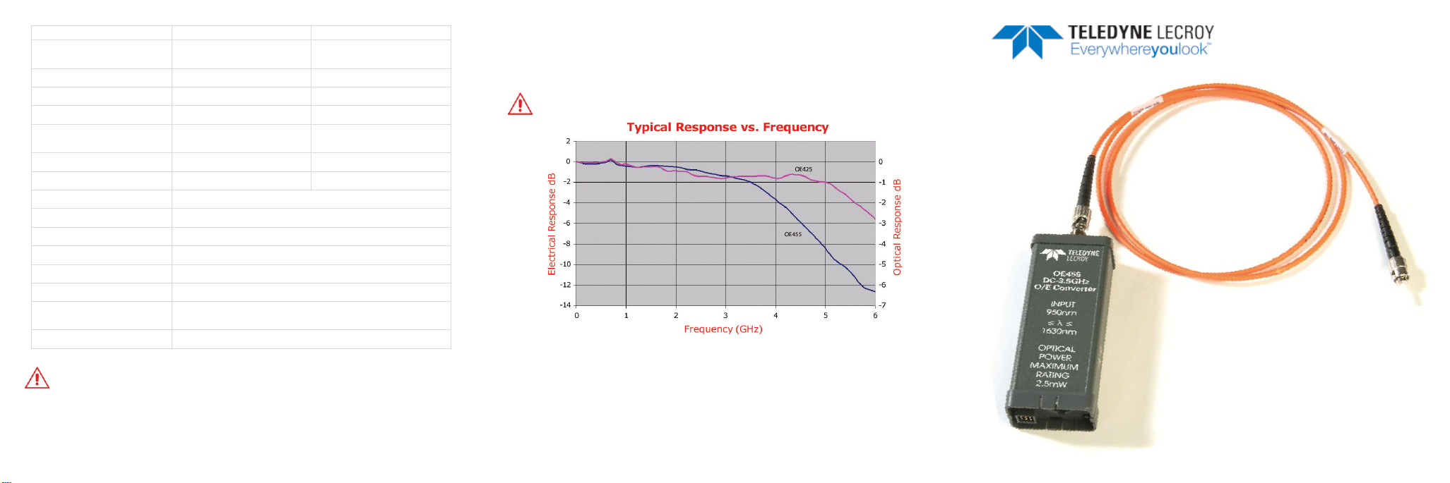
When used with a WaveMaster or WavePro series oscilloscope, the converters have a response vs.
frequency that follows a 4th order Bessel-Thompson lowpass filter whose -3 dB cutoff frequency is
set by the user-adjustable data rate. This filter adapts to the probe automatically, so it remains
calibrated regardless of the channel on which it is used.
Quantity of Light
What the scope displays is actually the voltage resulting from the conversion of the light signal by an
optical-to-electrical converter. The efficiency of this conversion (V/W) depends on the wavelength of
the incident light.
The OE4x5 and OE5x5 are designed to operate optimally over different wavelengths:
OE455 and OE555 operate over the 950 to 1630 nm range
OE425 and OE525 operate over the 500 to 870 nm range
The probes are calibrated at 1550 nm and 800 nm, respectively.
Therefore, when other wavelengths of light are measured, the power displayed by the scope will
differ slightly from the actual value.
The detectors are “multimode”; they will remain accurate when used with either single or multimode
optical fibers.
Another factor affecting the measurement of power is the insertion loss of cables chained between
the light source and the probe. Each optical connection will typically cost between 0.3 and 0.5 dB
(7% to 12%) of light output. Scope calibration is based on light at the probe FC connector.
Measurements of Small Amounts of Light
Through “Enhanced Resolution” and “Averaging” of mathematical functions, it is possible to
measure very small signals that represent minute amounts of light. However, the offsets generated
by temperature changes can become significant. If the absolute amount of light is to be measured,
you should plan for frequent scope re-calibrations, or minimize temperature variations. But if only the
amplitude of light modulation is to be measured, this is not critical.
Operation with Oscilloscope
The OE4x5 probes use ProBus style connectors. Therefore, a BNC-BMA adapter is required when
they are to be used with a WaveMaster oscilloscope.
The probe response can be read directly from the oscilloscope Probe dialog, which will have the
same name as the connected converter. From the Vertical drop-down menu, select the channel to
which the OE is connected, then click the <probe> tab. The probe information is listed at the right of
the dialog and the reference receiver filter selection is shown at the left. The reference receiver is set
to a given standard by selecting it from Receiver Standard.
You can also select a user-defined filter from Receiver Standard, then enter either the Receiver
Bandwidth or Data Rate in the appropriate field. These two values are related in that the receiver
bandwidth is 75% of the data rate. Only one of the two parameters need be entered; the other will be
computed automatically.
A selection is also available for disabling the reference receiver filter.
When the probes are used with the WaveMaster or WavePro series oscilloscope in combination with
the universal reference receiver, the probe response is automatically matched to the scope and
channel, and the bandwidth response is adjusted to the user-selected data rate.
Optical Reference Receiver Background Information
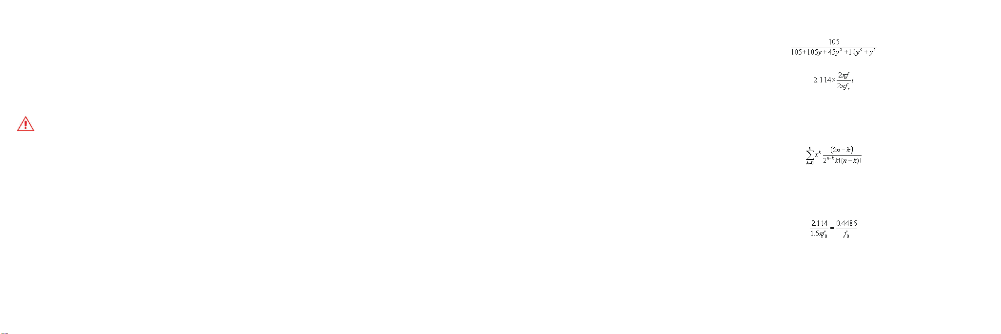
An Optical Reference Receiver has a filter that implements the transfer function:
Where y is defined as:
and ƒr is the reference frequency (chosen as 0.75ƒ0) and ƒ0 is the bit rate (for example, 2.4488 GHz
for OC48/STM4). The form of the transfer function is the inverse of a Bessel Polynomial (see Krall,
H. L. and Fink, O., “A New Class of Orthogonal Polynomials: The Bessel Polynomials,” Trans. Amer.
Math. Soc. 65, 100-115, 1948). Filters implementing Bessel polynomials as denominators of the
transfer function are called Thompson filters, hence the name “fourth order Thompson-Bessel” for
the transfer function. The order n Bessel polynomial is simply given by the formula:
The factor 2.114 in Equation 2 simply ensures that the norm squared of the transfer function reaches
(the “-3 dB point”) at the reference frequency. The main property of the Bessel- Thompson filter is a
minimal group delay distortion. The group delay is defined by the derivative of the phase delay with
respect to the frequency of an input sine wave. When quoted in “UI,” the group delay is normalized to
the bit rate’s period. The group delay of the fourth-order Bessel-Thompson filter at low frequencies
is:
The group delay diminishes monotonically, reaching 0.1512 UI at a frequency of two times the bit
rate. The difference between the group delay at zero frequency and the group delay at a given
frequency is called the group delay distortion. The conformity of the response to the specifications
for the combination of probe and scope channel is verified in detail on a clean optical impulse at the
factory.
922263-00 Rev A
 Loading...