

Page 1
OC1024-A Instrument Cart
Assembly Instructions and User’s Manual
PN LEC5450 REV A
1
Page 2
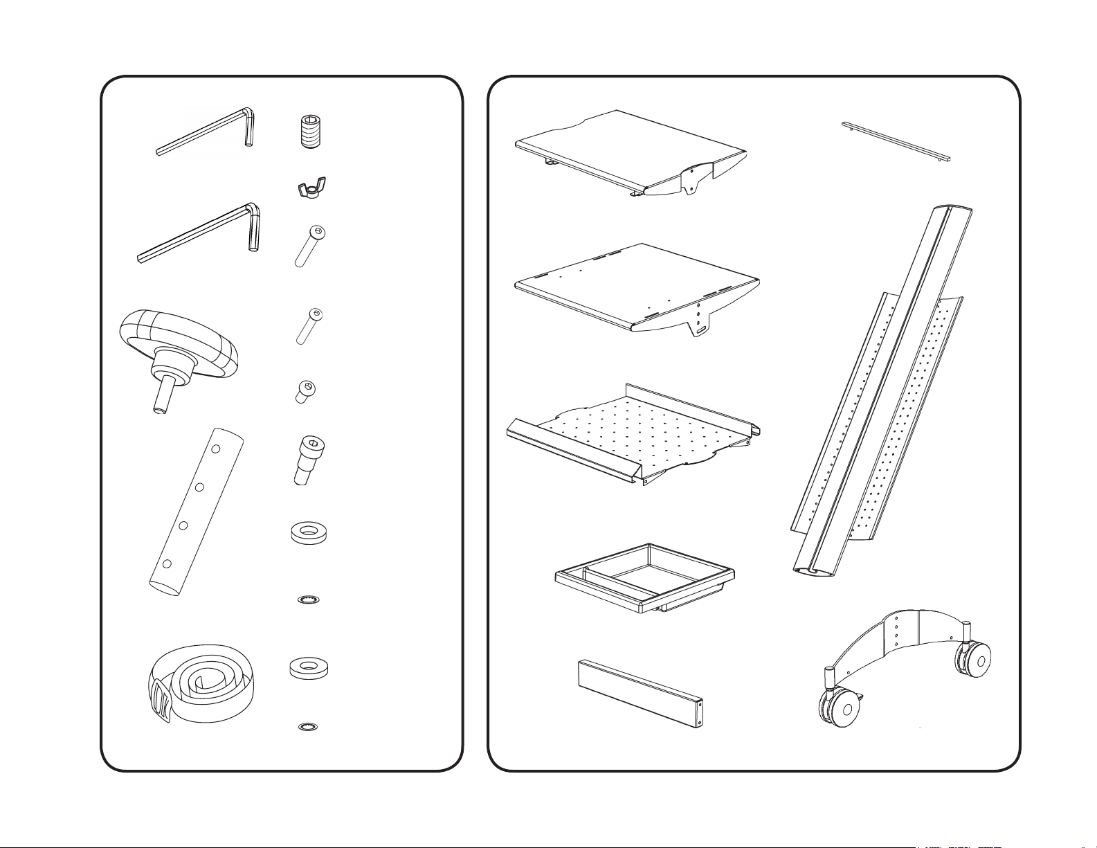
4 Set Screws
Small Hex Wrench (1/8)
Large Hex Wrench (5/32)
2 Knobs
1 Retaining Bar
2 Wing Nuts
1 Top Shelf
2 Long Screws
18 Short Screws
1 Middle Shelf
4 Small Screws
2 Shoulder Screws
1 Bottom Tray
6 Plastic Washers
8 Rods
2 Straps
20 Large Lock
Washers
2 Metal Washers
4 Small Lock
Washers
1 Drawer
1 Support Bar
2 Posts
2 Legs
2
Page 3
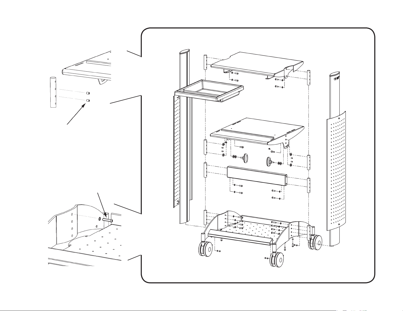
Note: Correct installation of Set Screw
and Long Screw necessary for proper
performance of cart.
3
Page 4

1
2
!
Large Wrench
4 Short
Screws
4 Large Lock
Washers
2 Rods
3
Illustration 1: The cart will be assembled laying down. First, loosely preassemble the Rods to the Top Shelf with the Short Screws
and Large Lock Washers using placement as shown. Note the placement of the tab on the Top Shelf, this tab will be used
to orient other parts during the assembly.
Illustration 2 and 3: Slide assembly to the end of the posts and lightly tighten the Short Screws.
4
Page 5

4
Small Wrench
2 Metal
Washers
!
5
Metal Washer
Plastic Washers
Plastic Washer
2 Knobs
2 Rods
6 Plastic
Washers
4 Set Screws
6
2 Shoulder
Screws
Illustration 4: Loosely preassemble 2 Rods and all Shoulder Screws, Knobs, Plastic Washers, and Metal Washers to the Middle
Shelf using the placement as shown. Use the Small Wrench to insert the Set Screws into the Rod through the Middle Shelf.
Illustration 5 and 6: Note the orientation of the slots in the Middle Shelf and the tab on the Top Shelf and slide the assembly to the
center of the Posts and tighten the Knobs.
5
Page 6

Large Wrench
4 Short
Screws
87
!
2 Rods
4 Large Lock
Washers
Illustration 7 and 8: Loosely preassemble the Support Bar, Short Screws, Rods and Large Lock Washers as shown.
Illustration 9: Orient the Support Bar to the tab in the Top Shelf and slide it a few inches below the Middle Shelf. Lightly tighten.
9
6
Page 7

10
11
Small Wrench
4 Small Lock
Washers
4 Small
Screws
Illustration 10 and 11: Firmly tighten the Leg to the Bottom Tray with the Small Screws and Small Lock Washers as shown.
7
Page 8

12
14
!
Large Wrench
2 Large Lock
Washers
13
!
!
2 Long
Screws
2 Rods
Illustration 12: Loosely preassemble the two Long Screws and two Rods with Large Lock Washers to the Legs.
Illustration 13: Orient the nonlocking caster with the tab in the Top Shelf and slide the Leg and Tray Assembly onto the Posts.
Illustration 14: Fit the Long Screws into the mating hole inside the Posts, lightly tighten the screw ensuring it has correctly
engaged the hole.
8
Page 9

15
17
!
Large Wrench
Small Wrench
26”
15.5”
!
16
Illustration 15: Firmly tighten the 4 Short Screws and Large Lock Washers into the Bottom Tray as shown.
Illustration 16: Firmly tighten the 6 Short Screws and Large Lock Washers into the Legs as shown.
Illustration 17: Carefully stand the cart upright as it will sway somewhat. Adjust the Support Bar to be 15.5” from the Tray.
Ensure that the cart is vertical, then rmly tighten the Support Bar screws. Adjust the Middle Shelf 26” from the Tray, and rmly tighten
the Middle Shelf’s 4 Set Screws, Shoulder Screws and Knobs. Adjust the Top shelf to the top of the Posts, and rmly tighten the 4
Short Screws and the 2 Long Screws in the Legs. Install the Drawer.
10 Large Lock
Washers
10 Short
Screws
9
Page 10

18
19
2 Wing Nuts
Slots
2 Straps
Illustration 18: The Retaining Bar attaches to the Top Shelf in one of two places. Measure the scope from the front to the front
most feet and Firmly tighten the bar in the appropriate position with the Wing Nuts. Strap the scope to the cart using
the front most slot and one of the two rear most slots on the Middle Shelf.
Illustration 19: Loosen the Knobs, tilt the Middle Shelf to the desired postition, and then tighten the Knobs to secure the shelf.
10
 Loading...