

Page 1
3385 Scott Blvd, Santa Clara, CA 95054 Tel: +1/408.727.6600 Fax: +1/408.727.6622
CATC Merlin II
™
Bluetooth™ Protocol Analyzer
User’s Manual
Manual Revision 2.50
For Software Version 2.50
18 July, 2004
Page 2

Merlin II Protocol Analyzer User’s ManualCATC SW Version 2.50
Document Disclaimer
The information contained in this document has been carefully checked and
is believed to be reliable. However, no responsibility can be assumed for
inaccuracies that may not have been detected.
CATC reserves the right to revise the information presented in this
document without notice or penalty.
Trademarks and Servicemarks
CATC, Merlin II, BTTracer, BTTrainer, Merlin, Merlin’s Wand, Merlin
Mobile, and BusEngine are trademarks of Computer Access Technology
Corporation.
Microsoft, Windows NT, Windows 2000, Windows 98SE, Windows ME, and
Windows XP are registered trademarks of Microsoft Inc.
All other trademarks are property of their respective companies.
Copyright
Copyright © 2004, Computer Access Technology Corporation (CATC); All
Rights Reserved.
Portions of this product are supplied courtesy of Richard Herveille.
Copyright (c) 2002, 2003 Richard Herveille, rherveille@opencores.org. All
rights reserved.
This document may be printed and reproduced without additional
permission, but all copies should contain this copyright notice.
FCC Conference Statement
This equipment has been tested and found to comply with the limits for a
Class A digital device and an intentional radiator, pursuant to Part 15 of the
FCC Rules. These limits are designed to provide reasonable protection
against harmful interference when the equipment is operated in a
commercial environment. This equipment generates, uses, and can radiate
radio frequency energy and, if not installed and used in accordance with the
instruction manual, may cause harmful interference to radio
communications. Operation of this equipment in a residential area is likely
to cause harmful interference in which case the user will be required to
correct the interference at their own expense. The end user of this product
should be aware that any changes or modifications made to this equipment
without the approval of CATC could result in the product not meeting the
Class A limits, in which case the FCC could void the user's authority to
operate the equipment.
ii
Page 3

Merlin II Protocol Analyzer User’s ManualCATC SW Version 2.50
Important Notice: To comply with FCC RF exposure requirements
(sections 1.1307 and 1.310 of the Rules) only the antenna supplied by
CATC must be used for this device. The anten na must be loca ted at least 20
cm away from all persons.
FCC Testing applies to FCC ID: KH7BT006UAA-X.
EU Conference Statement
This equipment complies with the R&TT Directive 1999/5/EC. It has been
tested and found to comply with EN55022:1994/A1:1995/A2:1997 Class A,
EN61000-4-2:1995, EN61000-4-3:1995, EN61000-4-4:1995,
EN61000-4-5:1995, EN61000-4-6:1995, EN61000-4-11:1994,
EN61010-1:1993, and ESTI EN 300 328-1 V1.2.2 (2000-07).
Manual Version 2.50 Part number: 730-0055-00
iii
Page 4

Merlin II Protocol Analyzer User’s ManualCATC SW Version 2.50
iv
Page 5

Merlin II Protocol Analyzer User’s ManualCATC SW Version 2.50
TABLE OF CONTENTS
Chapter 1 Overview . . . . . . . . . . . . . . . . . . . . . . . . . . . . . . . . . . . . . 1
Bluetooth™ Overview . . . . . . . . . . . . . . . . . . . . . . . . . . . . . . . . . . . . . . . . . . . . . .1
General Description . . . . . . . . . . . . . . . . . . . . . . . . . . . . . . . . . . . . . . . . . . . . . . .2
Automation. . . . . . . . . . . . . . . . . . . . . . . . . . . . . . . . . . . . . . . . . . . . . . . . . . . . . . .3
Features . . . . . . . . . . . . . . . . . . . . . . . . . . . . . . . . . . . . . . . . . . . . . . . . . . . . . . . . .3
General . . . . . . . . . . . . . . . . . . . . . . . . . . . . . . . . . . . . . . . . . . . . . . . . . . .3
Physical Components . . . . . . . . . . . . . . . . . . . . . . . . . . . . . . . . . . . . . . . .4
Display Options . . . . . . . . . . . . . . . . . . . . . . . . . . . . . . . . . . . . . . . . . . . .4
Recording Options . . . . . . . . . . . . . . . . . . . . . . . . . . . . . . . . . . . . . . . . . .4
Bluetooth BusEngine . . . . . . . . . . . . . . . . . . . . . . . . . . . . . . . . . . . . . . . .5
Specifications. . . . . . . . . . . . . . . . . . . . . . . . . . . . . . . . . . . . . . . . . . . . . . . . . . . . .6
Package . . . . . . . . . . . . . . . . . . . . . . . . . . . . . . . . . . . . . . . . . . . . . . . . . .6
Power Requirements. . . . . . . . . . . . . . . . . . . . . . . . . . . . . . . . . . . . . . . . .6
Radio. . . . . . . . . . . . . . . . . . . . . . . . . . . . . . . . . . . . . . . . . . . . . . . . . . . . .7
Environmental Conditions . . . . . . . . . . . . . . . . . . . . . . . . . . . . . . . . . . . .7
LEDs . . . . . . . . . . . . . . . . . . . . . . . . . . . . . . . . . . . . . . . . . . . . . . . . . . . .7
Recording Size . . . . . . . . . . . . . . . . . . . . . . . . . . . . . . . . . . . . . . . . . . . . .7
Host Compatibility . . . . . . . . . . . . . . . . . . . . . . . . . . . . . . . . . . . . . . . . . .7
Chapter 2 Installation . . . . . . . . . . . . . . . . . . . . . . . . . . . . . . . . . . . 9
System Components/Packing List . . . . . . . . . . . . . . . . . . . . . . . . . . . . . . . . . . . . .9
Analyzer LED Descriptions. . . . . . . . . . . . . . . . . . . . . . . . . . . . . . . . . . . . . . . . . .9
Rear Panel Description. . . . . . . . . . . . . . . . . . . . . . . . . . . . . . . . . . . . . . . . . . . . . .9
Setting Up the Analyzer. . . . . . . . . . . . . . . . . . . . . . . . . . . . . . . . . . . . . . . . . . . .10
Installing the Analyzer Software on the PC. . . . . . . . . . . . . . . . . . . . . . . . . . . . .10
Your First Bluetooth Recording. . . . . . . . . . . . . . . . . . . . . . . . . . . . . . . . . . . . . .13
Inquiry Recording. . . . . . . . . . . . . . . . . . . . . . . . . . . . . . . . . . . . . . . . . .13
External Interface Breakout Board . . . . . . . . . . . . . . . . . . . . . . . . . . . . . . . . . . .15
Connecting the Breakout Board . . . . . . . . . . . . . . . . . . . . . . . . . . . . . .16
Configuring the Analyzer for the Breakout Board . . . . . . . . . . . . . . . . .16
Chapter 3 Updates . . . . . . . . . . . . . . . . . . . . . . . . . . . . . . . . . . . . . 17
Update Files . . . . . . . . . . . . . . . . . . . . . . . . . . . . . . . . . . . . . . . . . . . . . . . . . . . . .17
Automatic Updates. . . . . . . . . . . . . . . . . . . . . . . . . . . . . . . . . . . . . . . . . . . . . . . .17
Software, Firmware, and BusEngine Versions . . . . . . . . . . . . . . . . . . . . . . . . . .19
Software Updates. . . . . . . . . . . . . . . . . . . . . . . . . . . . . . . . . . . . . . . . . . . . . . . . .19
License Information. . . . . . . . . . . . . . . . . . . . . . . . . . . . . . . . . . . . . . . . . . . . . . .20
Updating the Software License. . . . . . . . . . . . . . . . . . . . . . . . . . . . . . . .20
Chapter 4 Software Overview. . . . . . . . . . . . . . . . . . . . . . . . . . . . 23
The Main Display Windows . . . . . . . . . . . . . . . . . . . . . . . . . . . . . . . . . . . . . . . .23
Toolbar. . . . . . . . . . . . . . . . . . . . . . . . . . . . . . . . . . . . . . . . . . . . . . . . . . . . . . . . .26
Status Bar. . . . . . . . . . . . . . . . . . . . . . . . . . . . . . . . . . . . . . . . . . . . . . . . . . . . . . .32
Recording Progress. . . . . . . . . . . . . . . . . . . . . . . . . . . . . . . . . . . . . . . . .32
Status Bar Position Definitions: . . . . . . . . . . . . . . . . . . . . . . . . . . . . . . .32
v
Page 6

Merlin II Protocol Analyzer User’s ManualCATC SW Version 2.50
Recording Status. . . . . . . . . . . . . . . . . . . . . . . . . . . . . . . . . . . . . . . . . . .34
Analyzer Status. . . . . . . . . . . . . . . . . . . . . . . . . . . . . . . . . . . . . . . . . . . .34
Search Status. . . . . . . . . . . . . . . . . . . . . . . . . . . . . . . . . . . . . . . . . . . . . .35
Zooming In and Out. . . . . . . . . . . . . . . . . . . . . . . . . . . . . . . . . . . . . . . . . . . . . . .35
Zoom In. . . . . . . . . . . . . . . . . . . . . . . . . . . . . . . . . . . . . . . . . . . . . . . . . .35
Zoom Out . . . . . . . . . . . . . . . . . . . . . . . . . . . . . . . . . . . . . . . . . . . . . . . .35
Tool Tips . . . . . . . . . . . . . . . . . . . . . . . . . . . . . . . . . . . . . . . . . . . . . . . . . . . . . . .35
Merlin II Analyzer Keyboard Shortcuts. . . . . . . . . . . . . . . . . . . . . . . . . . . . . . . .36
Chapter 5 Recording Wizard . . . . . . . . . . . . . . . . . . . . . . . . . . . . 37
Starting Recording Wizard . . . . . . . . . . . . . . . . . . . . . . . . . . . . . . . . . . .37
Recording a Traffic on a New Piconet. . . . . . . . . . . . . . . . . . . . . . . . . . . . . . . . .38
Recording an Existing Piconet . . . . . . . . . . . . . . . . . . . . . . . . . . . . . . . . . . . . . .48
Recording in Test Mode . . . . . . . . . . . . . . . . . . . . . . . . . . . . . . . . . . . . . . . . . . . .57
Recording in Reduced Hopping Mode . . . . . . . . . . . . . . . . . . . . . . . . . .57
Recording in Single Frequency Mode . . . . . . . . . . . . . . . . . . . . . . . . . . . . . . . . .61
Chapter 6 Recording Options . . . . . . . . . . . . . . . . . . . . . . . . . . . . 65
Recording Modes. . . . . . . . . . . . . . . . . . . . . . . . . . . . . . . . . . . . . . . . . . . . . . . . .65
Piconet recording . . . . . . . . . . . . . . . . . . . . . . . . . . . . . . . . . . . . . . . . . .65
Inquiry recording . . . . . . . . . . . . . . . . . . . . . . . . . . . . . . . . . . . . . . . . . .65
UT:HCI mode . . . . . . . . . . . . . . . . . . . . . . . . . . . . . . . . . . . . . . . . . . . . .6 6
Opening the Recording Options Dialog Box. . . . . . . . . . . . . . . . . . . . . . . . . . . .66
Recording Options - General . . . . . . . . . . . . . . . . . . . . . . . . . . . . . . . . . . . . . . . .6 7
Recording type . . . . . . . . . . . . . . . . . . . . . . . . . . . . . . . . . . . . . . . . . . . .67
Options . . . . . . . . . . . . . . . . . . . . . . . . . . . . . . . . . . . . . . . . . . . . . . . . . .67
Buffer Size . . . . . . . . . . . . . . . . . . . . . . . . . . . . . . . . . . . . . . . . . . . . . . .68
Trigger Position . . . . . . . . . . . . . . . . . . . . . . . . . . . . . . . . . . . . . . . . . . . 68
Debug . . . . . . . . . . . . . . . . . . . . . . . . . . . . . . . . . . . . . . . . . . . . . . . . . . .69
Recording Options - Piconet . . . . . . . . . . . . . . . . . . . . . . . . . . . . . . . . . . . . . . . .69
Frequency Hopping. . . . . . . . . . . . . . . . . . . . . . . . . . . . . . . . . . . . . . . . .69
Sequence . . . . . . . . . . . . . . . . . . . . . . . . . . . . . . . . . . . . . . . . . . . . . . . . .71
Synchronization Method. . . . . . . . . . . . . . . . . . . . . . . . . . . . . . . . . . . . .71
Recording When Already Synchronized. . . . . . . . . . . . . . . . . . . . . . . . .73
When to Use the Different Piconet Recording Modes . . . . . . . . . . . . . .73
Loss of Sync Timeout (1-30 secs) . . . . . . . . . . . . . . . . . . . . . . . . . . . . .77
Force Re-synchronization. . . . . . . . . . . . . . . . . . . . . . . . . . . . . . . . . . . .77
Show Paging Traffic. . . . . . . . . . . . . . . . . . . . . . . . . . . . . . . . . . . . . . . .77
Follow Anonymity . . . . . . . . . . . . . . . . . . . . . . . . . . . . . . . . . . . . . . . . .77
Advanced ... . . . . . . . . . . . . . . . . . . . . . . . . . . . . . . . . . . . . . . . . . . . . . .78
Recording Options - HCI. . . . . . . . . . . . . . . . . . . . . . . . . . . . . . . . . . . . . . . . . . .80
Recording Options - Inquiry . . . . . . . . . . . . . . . . . . . . . . . . . . . . . . . . . . . . . . . .81
Recording Options - Events. . . . . . . . . . . . . . . . . . . . . . . . . . . . . . . . . . . . . . . . .82
Payload Length Error. . . . . . . . . . . . . . . . . . . . . . . . . . . . . . . . . . . . . . .88
Recording Options - Actions . . . . . . . . . . . . . . . . . . . . . . . . . . . . . . . . . . . . . . . .89
Action Buttons - Their Functions . . . . . . . . . . . . . . . . . . . . . . . . . . . . . .89
Blue Dot Menus . . . . . . . . . . . . . . . . . . . . . . . . . . . . . . . . . . . . . . . . . . . 9 2
vi
Page 7

Merlin II Protocol Analyzer User’s ManualCATC SW Version 2.50
Saving Recording Options . . . . . . . . . . . . . . . . . . . . . . . . . . . . . . . . . . . . . . . . . .96
Recording Bluetooth Traffic . . . . . . . . . . . . . . . . . . . . . . . . . . . . . . . . . . . . . . . .96
Taking "Snapshots" during a Long Recording. . . . . . . . . . . . . . . . . . . . . . . . . . .97
Chapter 7 Display Options . . . . . . . . . . . . . . . . . . . . . . . . . . . . . . 99
General Display Options . . . . . . . . . . . . . . . . . . . . . . . . . . . . . . . . . . . . . . . . . .100
Setting Color, Formatting, and Hiding Options. . . . . . . . . . . . . . . . . . . . . . . . .101
Setting Color Display Options . . . . . . . . . . . . . . . . . . . . . . . . . . . . . . .101
Changing Field Formats . . . . . . . . . . . . . . . . . . . . . . . . . . . . . . . . . . . .102
Hiding Display Options . . . . . . . . . . . . . . . . . . . . . . . . . . . . . . . . . . . .103
Level Hiding Options. . . . . . . . . . . . . . . . . . . . . . . . . . . . . . . . . . . . . . . . . . . . .103
Level Hiding Parameters. . . . . . . . . . . . . . . . . . . . . . . . . . . . . . . . . . . .103
Saving Display Options . . . . . . . . . . . . . . . . . . . . . . . . . . . . . . . . . . . . . . . . . . .105
Chapter 8 Reading a CATC Trace . . . . . . . . . . . . . . . . . . . . . . . 107
Trace View Features . . . . . . . . . . . . . . . . . . . . . . . . . . . . . . . . . . . . . . . . . . . . .107
Interpreting the Displayed Information . . . . . . . . . . . . . . . . . . . . . . . . . . . . . . .107
Timing Analysis. . . . . . . . . . . . . . . . . . . . . . . . . . . . . . . . . . . . . . . . . . . . . . . . .108
Tooltips . . . . . . . . . . . . . . . . . . . . . . . . . . . . . . . . . . . . . . . . . . . . . . . . . . . . . . .109
Set Marker . . . . . . . . . . . . . . . . . . . . . . . . . . . . . . . . . . . . . . . . . . . . . . . . . . . . .109
Edit or Clear Marker . . . . . . . . . . . . . . . . . . . . . . . . . . . . . . . . . . . . . . . . . . . . .110
Setting Markers While Recording . . . . . . . . . . . . . . . . . . . . . . . . . . . . . . . . . . .111
Adding Comments to a Trace File. . . . . . . . . . . . . . . . . . . . . . . . . . . . . . . . . . .111
Expanded and Collapsed Data Formats. . . . . . . . . . . . . . . . . . . . . . . . . . . . . . .112
Hide Frequency Hops. . . . . . . . . . . . . . . . . . . . . . . . . . . . . . . . . . . . . . . . . . . . .113
Hide Nulls and Polls. . . . . . . . . . . . . . . . . . . . . . . . . . . . . . . . . . . . . . . . . . . . . .113
Menus in Clicked Fields. . . . . . . . . . . . . . . . . . . . . . . . . . . . . . . . . . . . . . . . . . .114
Hide Unassociated Traffic . . . . . . . . . . . . . . . . . . . . . . . . . . . . . . . . . . . . . . . . .114
Hide Channel . . . . . . . . . . . . . . . . . . . . . . . . . . . . . . . . . . . . . . . . . . . . . . . . . . .114
Hide Duplicated Traffic . . . . . . . . . . . . . . . . . . . . . . . . . . . . . . . . . . . . . . . . . . .114
Chapter 9 Searching Traces . . . . . . . . . . . . . . . . . . . . . . . . . . . . 115
Search Menu. . . . . . . . . . . . . . . . . . . . . . . . . . . . . . . . . . . . . . . . . . . . . . . . . . . .115
Go to Trigger. . . . . . . . . . . . . . . . . . . . . . . . . . . . . . . . . . . . . . . . . . . . .115
Go to Packet/Message/Protocol . . . . . . . . . . . . . . . . . . . . . . . . . . . . . .115
Go to Marker. . . . . . . . . . . . . . . . . . . . . . . . . . . . . . . . . . . . . . . . . . . . .116
Go to . . . . . . . . . . . . . . . . . . . . . . . . . . . . . . . . . . . . . . . . . . . . . . . . . . .116
Error . . . . . . . . . . . . . . . . . . . . . . . . . . . . . . . . . . . . . . . . . . . . . . . . . . .120
Soft Bit Error. . . . . . . . . . . . . . . . . . . . . . . . . . . . . . . . . . . . . . . . . . . . .120
Loss of Sync . . . . . . . . . . . . . . . . . . . . . . . . . . . . . . . . . . . . . . . . . . . . .120
Find . . . . . . . . . . . . . . . . . . . . . . . . . . . . . . . . . . . . . . . . . . . . . . . . . . . .120
Event Groups . . . . . . . . . . . . . . . . . . . . . . . . . . . . . . . . . . . . . . . . . . . .122
Union, Intersection, and Exclusion. . . . . . . . . . . . . . . . . . . . . . . . . . . .125
Using Find. . . . . . . . . . . . . . . . . . . . . . . . . . . . . . . . . . . . . . . . . . . . . . .126
Find Next . . . . . . . . . . . . . . . . . . . . . . . . . . . . . . . . . . . . . . . . . . . . . . .128
Chapter 10 Decoding Protocols. . . . . . . . . . . . . . . . . . . . . . . . . . 129
Introduction . . . . . . . . . . . . . . . . . . . . . . . . . . . . . . . . . . . . . . . . . . . . . . . . . . . .129
vii
Page 8

Merlin II Protocol Analyzer User’s ManualCATC SW Version 2.50
LMP and L2CAP Messages. . . . . . . . . . . . . . . . . . . . . . . . . . . . . . . . . . . . . . . .129
Decoding and Viewing Higher Protocol Data . . . . . . . . . . . . . . . . . . . . . . . . . .130
Decoding Via the Decoding Toolbar . . . . . . . . . . . . . . . . . . . . . . . . . .130
Decoding Via the Display Options Dialog Box . . . . . . . . . . . . . . . . . .131
Tooltips . . . . . . . . . . . . . . . . . . . . . . . . . . . . . . . . . . . . . . . . . . . . . . . . . . . . . . .131
Viewing Packets in LMP and L2CAP Messages. . . . . . . . . . . . . . . . . . . . . . . .132
Types of LMP and L2CAP Messages . . . . . . . . . . . . . . . . . . . . . . . . . . . . . . . .132
Viewing L2CAP Channel Connections . . . . . . . . . . . . . . . . . . . . . . . . . . . . . . .133
Viewing Protocol Messages and Transactions. . . . . . . . . . . . . . . . . . . . . . . . . .134
Viewing L2CAP Messages in Protocol Messages . . . . . . . . . . . . . . . .134
How to Decode . . . . . . . . . . . . . . . . . . . . . . . . . . . . . . . . . . . . . . . . . . .134
Expanding Protocol Messages . . . . . . . . . . . . . . . . . . . . . . . . . . . . . . .134
Decoding via the Profiles Toolbar. . . . . . . . . . . . . . . . . . . . . . . . . . . . . . . . . . .135
Changing Protocol Assignments . . . . . . . . . . . . . . . . . . . . . . . . . . . . . . . . . . . .135
Using the Decoding Assignments Dialog Box . . . . . . . . . . . . . . . . . . .136
Removing User-Assigned Protocol Assignments. . . . . . . . . . . . . . . . .137
Manually Assigning Protocols . . . . . . . . . . . . . . . . . . . . . . . . . . . . . . .138
Other Assignments: OBEX Client/Server Status . . . . . . . . . . . . . . . . .138
Changing an OBEX Client or Server Status. . . . . . . . . . . . . . . . . . . . .139
Decoding BNEP . . . . . . . . . . . . . . . . . . . . . . . . . . . . . . . . . . . . . . . . . .139
Decoding HID. . . . . . . . . . . . . . . . . . . . . . . . . . . . . . . . . . . . . . . . . . . .139
Other Decoding Options. . . . . . . . . . . . . . . . . . . . . . . . . . . . . . . . . . . .139
Encryption . . . . . . . . . . . . . . . . . . . . . . . . . . . . . . . . . . . . . . . . . . . . . . . . . . . . .140
Configuring Merlin II for Encryption. . . . . . . . . . . . . . . . . . . . . . . . . .140
Re-applying Encryption Settings. . . . . . . . . . . . . . . . . . . . . . . . . . . . . . . . . . . .142
Chapter 11 Reports & Exporting Data . . . . . . . . . . . . . . . . . . . 145
Combining Report Windows . . . . . . . . . . . . . . . . . . . . . . . . . . . . . . . . . . . . . . .145
Device List. . . . . . . . . . . . . . . . . . . . . . . . . . . . . . . . . . . . . . . . . . . . . . . . . . . . .146
Traffic Summary . . . . . . . . . . . . . . . . . . . . . . . . . . . . . . . . . . . . . . . . . . . . . . . .148
Error Summary. . . . . . . . . . . . . . . . . . . . . . . . . . . . . . . . . . . . . . . . . . . . . . . . . .148
Bus Utilization . . . . . . . . . . . . . . . . . . . . . . . . . . . . . . . . . . . . . . . . . . . . . . . . . .149
Real-Time Log. . . . . . . . . . . . . . . . . . . . . . . . . . . . . . . . . . . . . . . . . . . . . . . . . .152
Real-Time Statistics. . . . . . . . . . . . . . . . . . . . . . . . . . . . . . . . . . . . . . . . . . . . . .153
File Information . . . . . . . . . . . . . . . . . . . . . . . . . . . . . . . . . . . . . . . . . . . . . . . . .157
Timing Calculations. . . . . . . . . . . . . . . . . . . . . . . . . . . . . . . . . . . . . . . . . . . . . .158
Exporting Trace Data. . . . . . . . . . . . . . . . . . . . . . . . . . . . . . . . . . . . . . . . . . . . .159
Exporting To Text Format . . . . . . . . . . . . . . . . . . . . . . . . . . . . . . . . . . . . . . . . .160
Exporting Trace Data to a .CSV Format . . . . . . . . . . . . . . . . . . . . . . . . . . . . . .160
Exporting Audio Data . . . . . . . . . . . . . . . . . . . . . . . . . . . . . . . . . . . . . . . . . . . .161
Appendix A: Merlin II Clock Calibration . . . . . . . . . . . . . . . . . 163
Procedure: . . . . . . . . . . . . . . . . . . . . . . . . . . . . . . . . . . . . . . . . . . . . . . . . . . . . .163
Appendix B: HCI Probe Description . . . . . . . . . . . . . . . . . . . . . 167
Connecting the HCI Probe. . . . . . . . . . . . . . . . . . . . . . . . . . . . . . . . . . . . . . . . .168
2-port RS232 to USB converter . . . . . . . . . . . . . . . . . . . . . . . . . . . . . .170
viii
Page 9

Merlin II Protocol Analyzer User’s ManualCATC SW Version 2.50
Appendix C: Export Audio Streams . . . . . . . . . . . . . . . . . . . . . . 173
File Structure . . . . . . . . . . . . . . . . . . . . . . . . . . . . . . . . . . . . . . . . . . . . . . . . . . .173
RIFF Chunk Type. . . . . . . . . . . . . . . . . . . . . . . . . . . . . . . . . . . . . . . . .173
Format Chunk - "fmt " . . . . . . . . . . . . . . . . . . . . . . . . . . . . . . . . . . . . .173
Data Chunk - "data" . . . . . . . . . . . . . . . . . . . . . . . . . . . . . . . . . . . . . . .173
Compatibility . . . . . . . . . . . . . . . . . . . . . . . . . . . . . . . . . . . . . . . . . . . . . . . . . . .176
How to Contact CATC . . . . . . . . . . . . . . . . . . . . . . . . . . . . . . . . . 179
Limited Hardware Warranty . . . . . . . . . . . . . . . . . . . . . . . . . . . 179
ix
Page 10

Merlin II Protocol Analyzer User’s ManualCATC SW Version 2.50
x
Page 11

Merlin II Protocol Analyzer User’s ManualCATC SW Version 2.50
1. Overview
The CATC Merlin II™ Protocol Analyzer is the newest member of CATC's
industry-leading line of high performance, Bluetooth protocol analyzers.
Preceded by CATC’s BTTracer™, Merlin™ and Merlin Mobile™
Analyzers, Merlin II has been designed using the same modular architecture
that made its predecessors highly successful in the serial bus protocol
analyzer market worldwide.
1.1 Bluetooth™ Overview
The Bluetooth wireless technology is set to revolutionize the personal
connectivity market by providing freedom from wired connections. It is a
specification for a small-form factor, low-cost radio solution providing links
between mobile computers, mobile phones and other portable handheld
devices, and connectivity to the internet.
The Bluetooth Special Interest Group (SIG), comprised of leaders in the
telecommunications, computing, and network industries, is driving
development of the technology and bringing it to market. The Bluetooth
SIG includes promoter companies 3Com, Ericsson, IBM, Intel, Lucent,
Microsoft, Motorola, Nokia and Toshiba, and more than 2500 SIG
members.
Bluetooth is a radio technology specification designed to transmit both
voice and data wirelessly, providing an easier way for a variety of mobile
computing, communications and other devices to communicate with one
another without the need for cables. Bluetooth could make possible what is
being called the personal-area network by allowing users to transmit small
amounts of data at 1M bit/sec with a range of 10 to 100 meters, depending
the power of the radio, over the 2.4-GHz radio frequency. The key benefits
of the Bluetooth technology are robustness, low complexity, low power and
low cost. Bluetooth employs a rapid frequency hopping mechanism to
minimize the effects of ‘collisions’ with other protocols and devices
operating in the same frequency band. Mechanisms exist for a Bluetooth
device to determine all devices in range as well as to request connection to
a piconet as either a master or a slave.
Please refer to the Bluetooth Specification, version 1.2 for details on the
protocol. The Bluetooth specification is available from the Bluetooth SIG at
its web site http://www.bluetooth.org/
1
Page 12

Merlin II Protocol Analyzer User’s ManualCATC SW Version 2.50
1.2 General Description
The Merlin II Protocol Analyzer is designed as a stand-alone unit that can
be easily configured and controlled by a portable or desktop PC connected
via its USB port. Merlin II provides users with the familiar ‘CATC Trace’
user interface that is the de facto industry standard for documenting the
performance of high-speed serial protocols.
Merlin II supports the functionality required to analyze all levels, including
the baseband, of the Bluetooth wireless protocol. The featured Radio
Interface allows users to probe and analyze transactions at the lowest level
within the Bluetooth architecture. By creating this "Point of Observation" or
probing point within the radio level packet view, the user can analyze all
levels of the protocol stack.
Merlin II is a non-intrusive testing tool for Bluetooth piconets providing
network traffic capture and analysis. Hardware triggering allows real-time
events to be captured from a piconet. Hardware filtering allows the filtering
out of fields, packets, and errors from the recording. Filtering allows users
to focus recordings on events of interest and to preserve recording memory
so that the recording time can be extended.
Recorded data is presented in colored graphics in a trace viewer application.
This application has advanced search and viewing capabilities that allow the
user to quickly locate specific data, errors and other conditions, thereby
focussing the user’s attention on events of interest.
Merlin II functions with any personal computer using the Windows 98SE,
Windows 2000, Windows ME, or Windows XP operating systems and
equipped with a functional USB interface. For an updated set of system
requirements for the host machine, please refer to the readme file.
The Analyzer is configured and controlled through a personal computer
USB port. It can be used with portable computers for field service and
maintenance as well as with desktop units in a development environment.
The Analyzer is easily installed by connecting a cable between the
computer’s USB port and the Analyzer’s USB port.
Merlin II provides on-the-fly detection of and triggering on such events as
Packet Headers and Errors. Whether recording manually or with a specified
trigger condition, Merlin II continuously records the bus data in a
wrap-around fashion until manually stopped or until the Trigger Event is
detected and a specified post-Trigger amount of bus data is recorded.
Upon detection of a triggering event, the analyzer continues to record data
up to a point specified by the user. Real-time detection of events can be
individually enabled or disabled to allow triggering on events as they
2
Page 13

Merlin II Protocol Analyzer User’s ManualCATC SW Version 2.50
happen. This includes predefined exception or error conditions and a
user-defined set of trigger events. The unit can also be triggered by an
externally supplied signal. The breakout board provides a path for externally
supplied trigger or timing data to be recorded along with bus traffic.
The breakout board also provides a path for Merlin II to transmit a trigger
signal.
The Merlin II software provides powerful search functions that enable
investigation of particular events and allow the software to identify and
highlight specific events. In addition to immediate analysis, you can print
any part of the data. Use the Save As feature to save the data on disk for later
viewing. The program also provides a variety of timing information and
data analysis reports.
1.3 Automation
The Merlin II software includes an Application Program Interface (API) for
developing testing programs and scripts in C++ and Visual Basic. The API
reproduces most of the commands embodied in the Merlin II trace viewer
software. This API allows users to automate procedures that otherwise have
to be run manually via the trace viewer software. The Automation API can
be run locally on the PC attached to Merlin II or remotely over a network
connection.
For further details, refer to the Automation API for CATC Bluetooth
Analyzers reference manual included in the installation CD-ROM. You can
also download the document from the CATC website.
1.4 Features
General
• Small form factor for mobility and easy placement.
• Flexible design - reconfigurable hardware for future enhancements.
• User friendly - the Graphical User Interface software of Merlin II
Analyzer is designed to be consistent with the ‘CATC Trace’ using color
and graphics to display Bluetooth traffic.
• Radio Level Point of Observation and Capture - traffic capture at the
Radio Level for comprehensive analysis.
• Complies with Bluetooth v1.2 specification.
• Supports point-to-point and point-to-multipoint Bluetooth piconets.
• Spool data to hard drive allowing for long recording sessions.
3
Page 14

Merlin II Protocol Analyzer User’s ManualCATC SW Version 2.50
• Automatic tracking of ESCO and Anonymity Modes.
• Supports 79 frequency hop standards, reduced frequency, fixed
frequency, and AFH.
• Automatic tracking of changes in the hopping scheme.
• Automatic tracking of whitened and non-whitened packets and traffic.
• Real time viewing of events and statistics.
• Free non-recording, view-only software available.
• Power-on self-diagnostics.
• Compliant with FCC class A requirements / meets all CE mark
requirements.
• Three year warranty and hot-line customer support.
Physical Components
Note For an updated description of requirements for the host machine, please refer to
the readme file.
• External small "power brick." Can also be powered by PS/2 power cable.
• Trace viewer software support for Microsoft Windows versions 98SE
and later.
Display Options
• Analyzes and displays a transaction-level view of piconet traffic with
accurate time-stamps and frequency hop information.
• Software analysis and data presentation at several protocol levels:
Baseband, LMP, HCI, L2CAP, SDP, RFCOMM, TCS, OBEX, HDLC,
BNEP, PPP, AT, HCRP, IP, TCP, UDP, HID, AVCTP, and AVDTP.
• Supports the following profiles: GAP, CIP, CTP, HCRP, HID, Intercom
Profile, LPP, PAN, SDAP, SPP, UDI, DUN, FAX, GEOP, HF, HP,
LAN, PAP, SAP, VCP, BPP, BIP, FTP, OPP, Synchronization Profile,
GAVDP, A2DP, AVRCP, VDP
Recording Options
• Flexible advanced triggering capabilities including - multiple triggering
modes, selective views, timing analysis, search functions, protocol
packet errors, transaction errors, packet type and destination device, data
patterns, or any of these trigger types in combination.
• User defined trigger position.
• Support for various piconet characteristics by enabling the user to
configure the synchronization method and recording parameters.
4
Page 15

Merlin II Protocol Analyzer User’s ManualCATC SW Version 2.50
• Real-time hardware filtering of captured traffic for optimizing analyzer
memory usage.
Bluetooth BusEngine
CATC’s BusEngine™ Technology is at the heart of the new Merlin II
Analyzer. The revolutionary BusEngine core uses state-of-the-art FPGA
technology and incorporates both the real-time recording engine and the
configurable building blocks that implement data/state/error detection,
triggering, capture filtering, external signal monitoring and event counting
& sequencing. And like the flash-memory-based firmware that controls its
operation, all BusEngine logic is fully field upgradeable, using
configuration files that can be downloaded from the CATC Website.
5
Page 16

Merlin II Protocol Analyzer User’s ManualCATC SW Version 2.50
1.5 Specifications
Package
Width: 6.05 inches (15.5 cm)
Depth: 3.0 inches (7.6 cm)
Height: 1.07 inches (2.7 cm)
Weight: 8.8 oz (246 grams)
Power Requirements
5V, 800mA
The provided external power supply operates on 100V-240V AC 50Hz - 60A
Connectors: DC power connection (for connecting the external power
supply or the PS/2 power cable)
Mini DIN
Host connection (USB, type ’B’)
Antenna (reverse polarity SMA)
6
Page 17

Merlin II Protocol Analyzer User’s ManualCATC SW Version 2.50
Radio
Bluetooth v1.1 qualified
Class 2
FCC and CE compliant
Environmental Conditions
Operating Range: 0 to 55 °C (32 to 131 °F)
Storage Range: -20 to 80 °C (-4 to 176 °F)
Humidity: 10 to 90%, non-condensing
LEDs
Status (STATUS) Illuminates blue when the analyzer is functioning properly
Synchronized (SYNC):
Flashes yellow during acquisition of the traffic hop
sequence, illuminates when analyzer is locked to the hop
sequence.
Recording (REC): Illuminates green when analyzer is actively recording data.
Recording Size
Internal 32 MB and Disk spooling capabilities provide large virtual memory for
long for recording sessions
Host Compatibility
Requires a PC with a USB port
Supports Windows 98/ME/NT/2000
7
Page 18

Merlin II Protocol Analyzer User’s ManualCATC SW Version 2.50
8
Page 19

Merlin II Protocol Analyzer User’s ManualCATC SW Version 2.50
2. Installation
The Merlin II Protocol Analyzer components and software are easily
installed and quickly ready to run on most Windows-based personal
computer systems. You can begin making Bluetooth recordings after
following these initial steps.
2.1 System Components/Packing List
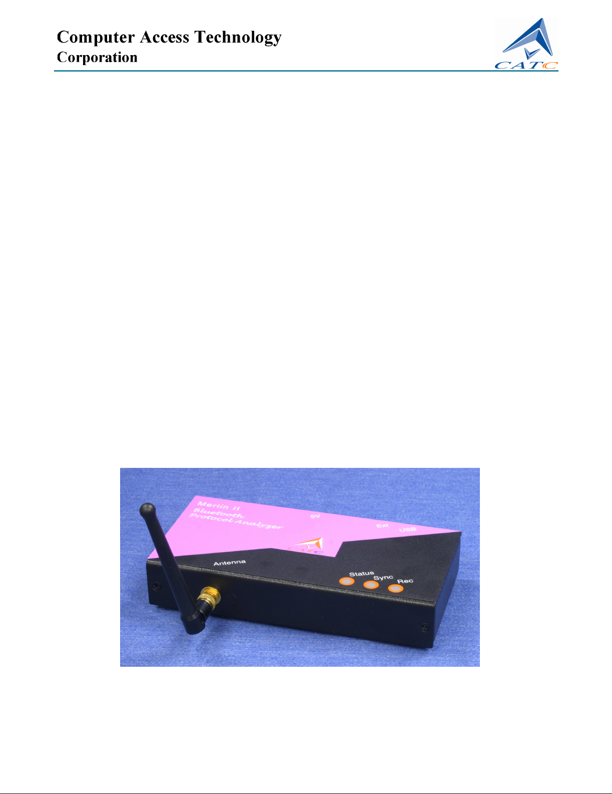
• One stand-alone Merlin II Analyzer
• One Antenna
• One External Interface Breakout Board with a Mini DIN cable
• One External Power Supply
• One PS/2 Power Cable
• One USB cable
• Merlin II software program installation CD
• User’s Manual
2.2 Analyzer LED Descriptions
The Merlin II analyzer has three LEDs. From left to right, these LEDs are:
A Blue Status indicator LED Blinks fast during initialization/power up.
Stead on if unit is functioning properly. Blinks slowly if a self-test fails..
B Yellow Sync (Synchronize) LED (Flashing indicates that the analyzer is
tracking the defined slave or master device. Illuminated indicates that
the analyzer is tracking an active piconet.)
C Green Rec (recording) LED (lights when the unit is recording).
2.3 Rear Panel Description
USB type "B" host computer connector
This connector links the analyzer to the PC that will be administering it.
Mini DIN Connector
This connector allows the analzyer to transmit and receive external signals
via a mini DIN cable to a Break Out Board for the purpose of triggering on
external input signals and for clock calibration.
9
Page 20

Merlin II Protocol Analyzer User’s ManualCATC SW Version 2.50
Power connector for external power supply
This connectors is used to attach the external power supply or for
connecting the analyzer with the provided PS/2 cable from a mouse or
keyboard serial port on the PC or laptop. The PS/2 cable is a pass-through
type that allows you to connect the cable to the PC and then plug the mouse
or keyboard into the back of the PS/2 cable.
2.4 Setting Up the Analyzer
To set up a Merlin II system,
Step 1 Attach the Antenna to the ANT connection point on the analyzer.
The antenna should point up.
Step 2 Connect the provided external power supply to the analyzer and then
to a 100-volt to 240-volt, 50 Hz to 60 Hz, 100 W power outlet.
Alternatively, you can connect the PS/2 cable into the analyzer and
one of your PS/2 ports (i.e. keyboard or mouse ports). The keyboard
or mouse would then plug into the back of the PS/2 cable.
Note At power-on, the analyzer initializes itself in approximately ten seconds and
performs an exhaustive self-diagnostic that lasts about five seconds. The status
LED flashes during the power-on testing and turns on steadily if the unit is
functioning properly when testing is finished. If the diagnostics fail, the status
LED blinks slowly, indicating a hardware failure. If this occurs, call CATC
Customer Support for assistance.
Step 3 Connect the USB cable between the USB port on the back of the
analyzer and a USB port on the analyzing PC.
The host operating system detects the analyzer and begins to install the USB
driver.
2.5 Installing the Analyzer Software on the PC
Once Merlin II has been recognized as a USB device, install the Merlin II
software on the PC administering the analyzer.
Step 1 Insert the Merlin II Suit e C D into the CD ROM dr ive of th e
PC that will be administering the Analyzer.
Step 2 Follow Windows on-screen Plug-and-Play instructions for the
automatic installation of the Merlin I I Analyzer as a USB device on
your analyzing PC (the required USB files are included on the
Merlin II CD.
10
Page 21
Merlin II Protocol Analyzer User’s ManualCATC SW Version 2.50
Step 3 Select Install Software from the installation CD and follow the
on-screen installation instructions.
The Merlin II application will install on the PC hard disk.
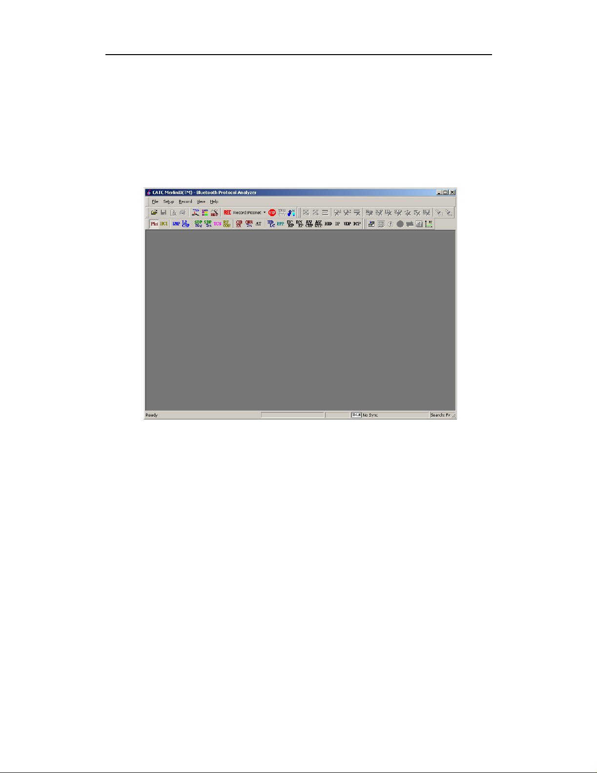
Step 4 To start the application, launch the CATC Merlin II program from
the Start Menu: Start>Programs>CATC>Merlin II.
The Merlin II program opens.
The window shows a menu bar and toolbar at the top, a grey trace viewing
area covering most of the window, and a status bar at the bottom.
Opening a sample trace will cause most of the buttons on the toolbar to
become active.
11
Page 22
Merlin II Protocol Analyzer User’s ManualCATC SW Version 2.50
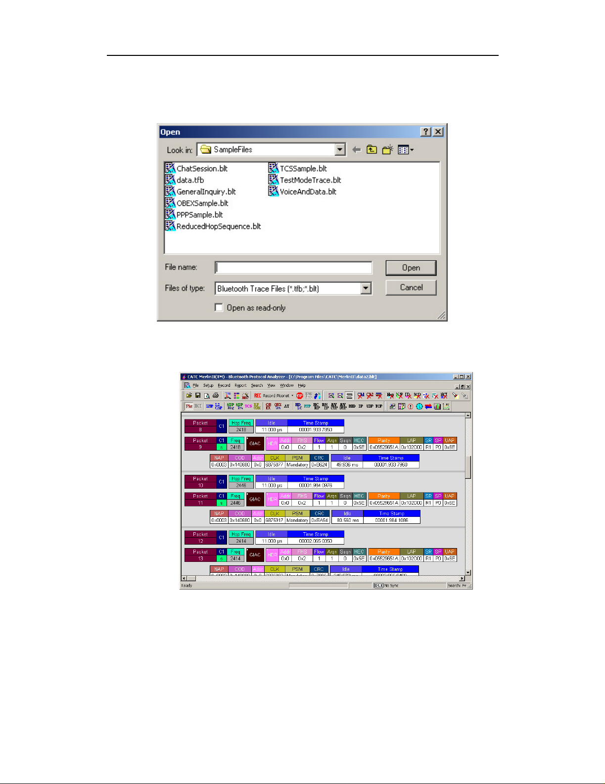
To open a trace,
Step 1 Select File > Open from the menu. A dialog box opens.
Step 2 Select a file from the dialog box and click Open. A trace opens in
the main viewing area. When traffic has been recorded, it will
display here.
Note The software may be used with or without the analyzer box. When used without
an analyzer box attached to the computer, the program functions as a Trace
Viewer to view, analyze, and print captured protocol traffic.
12
Page 23
Merlin II Protocol Analyzer User’s ManualCATC SW Version 2.50
2.6 Your First Bluetooth Recording
After installing and launching the software, you can test Merlin II by
creating an inquiry recording. In this test, Merlin II will issue a General
Inquiry that asks local devices to identify themselves. Merl in II then records
the responses.
Inquiry Recording
To create an inquiry recording, perform the following steps:
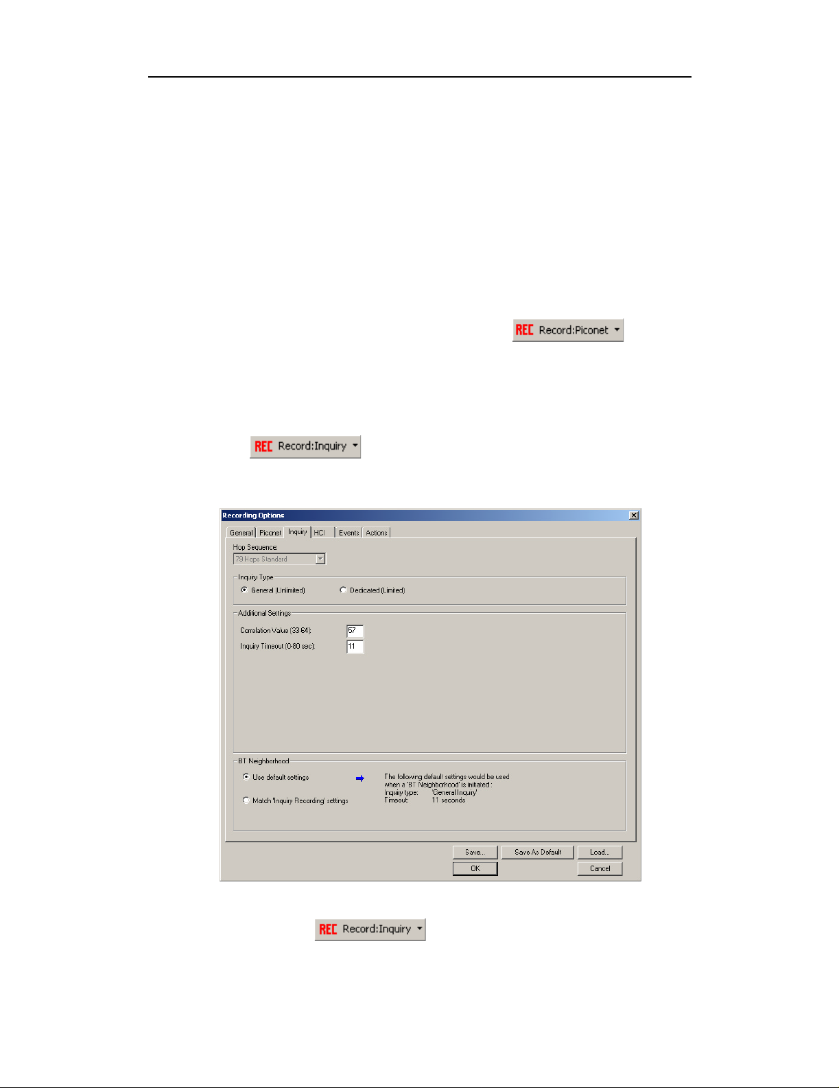
Step 1 Click the down-arrow on the right side of the
Record:Piconet button on the toolbar .
A sub-menu appears with options for Piconet Recording Mode, and Inquiry
Recording Mode.
Step 2 Select Inquiry Recording Mode.
The button changes appearance and shows the label Record: Inquiry
Step 3 From the menu, select Setup > Recording Options.
The Recording Options dialog opens with the Inquiry page displaying.
Step 4 If desired, make any changes to the options, then click OK.
Step 5 Click the button (i.e. not the down-arrow.)
13
Page 24
Merlin II Protocol Analyzer User’s ManualCATC SW Version 2.50
Merlin II starts to record the Bluetooth traffic immediately using the settings from
the Piconet page in the Recording Options dialog . The Bluetoo th Inquiry p rocess
will proceed for whatever amount of time is set for creating an Inquiry action (the
default is 11 seconds). After the inquiry time has elapsed, the analyzer will upload
the data and display the packets. In addition, the Device List window will open
and display the updated statuses of the devices.
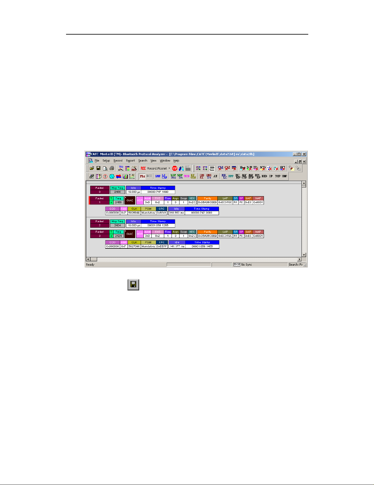
The screen should look like the sample recording below which shows the FHS
packets generated during the Inquiry process.
When the recording session is finished, the bus traffic is saved to the hard driv e as
a file named data.tfb or whatever name you assign as the default filename. While
the file is bei ng saved, you should see a brown progre ss bar at the bottom of the
screen. When the bar turns white, it indicates that the data has been saved to dis k.
Step 6 To save a current recording for future use, select File > Save As or
click on the tool bar.
You see the standard Save As screen.
Step 7 Give the recording a name and save it to the appropriate directory.
14
Page 25
Merlin II Protocol Analyzer User’s ManualCATC SW Version 2.50
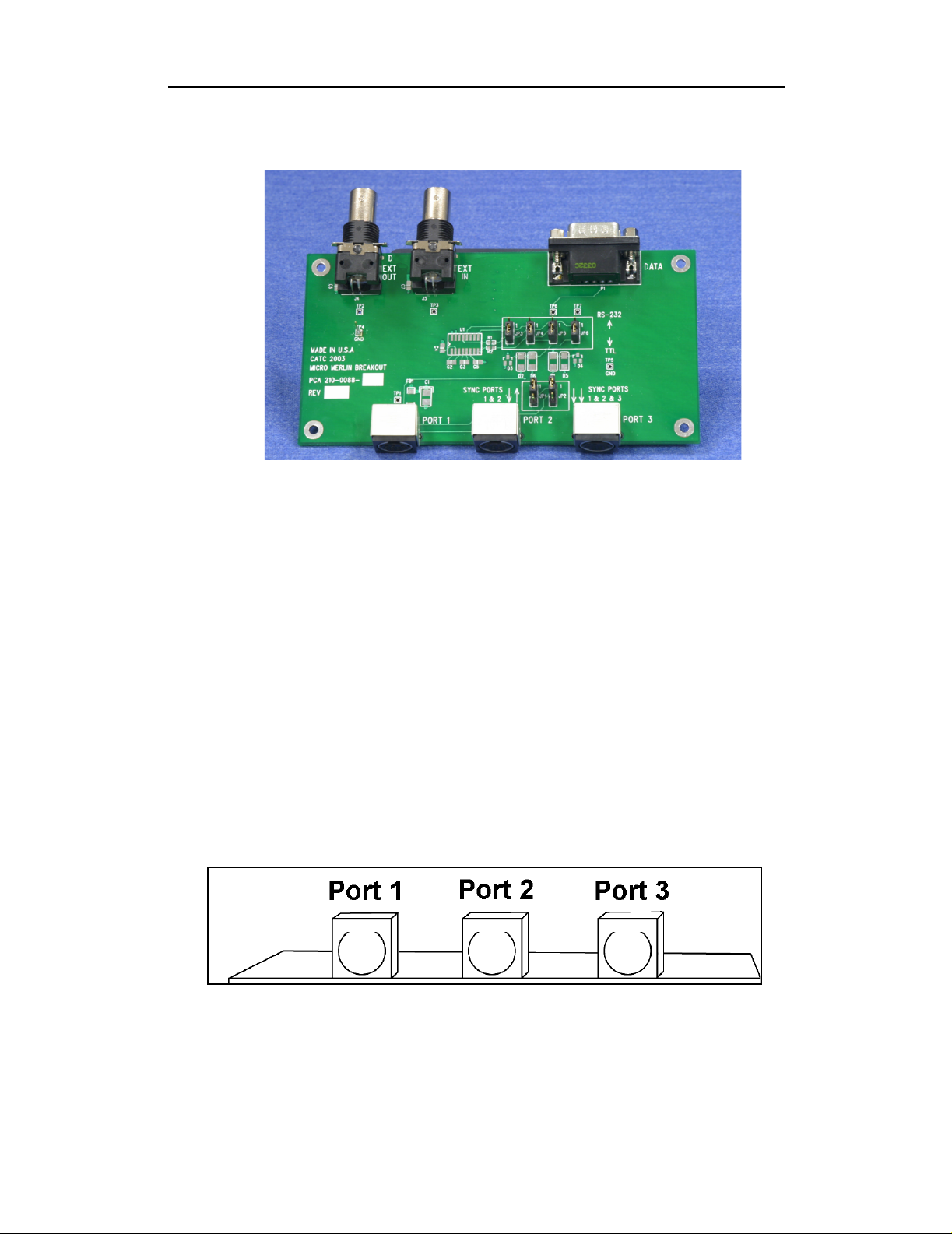
2.7 External Interface Breakout Board
The External Interface Breakout Board is an accessory that allows standard,
LV TTL signals to be connected to the analyzer for triggering. The breakout
board consists of two BNC connectors for "EXT IN" and "EXT OUT"
signals. The EXT IN connector can be used to import trigger signals from
other devices. the EXT OUT connector can be used to export trigger signals
to trigger other devices such as oscilloscopes or logic analyzers or to export
the external clock for clock calibration using a frequency counter (see
Appendix A).
Drive strength for all outputs is about 30mA high (@2V) and 60 mA low
(@0.5V). Inputs can handle 0 to 5.5V. Inputs above 2V are detected as logic
high; inputs below 0.8V are detected as logic low.
The analyzer connects to the first of three mini DIN ports ("Port 1") on the
Breakout Board. Each signaling pin is isolated by a 100Ω series resistor and
a buffer inside the Analyzer unit.
Please make sure that the jumpers JP1 and JP2 on the breakout board are set
to Position 1.
Mini DIN connectors on the back of the Break-out board.
15
Page 26
Merlin II Protocol Analyzer User’s ManualCATC SW Version 2.50
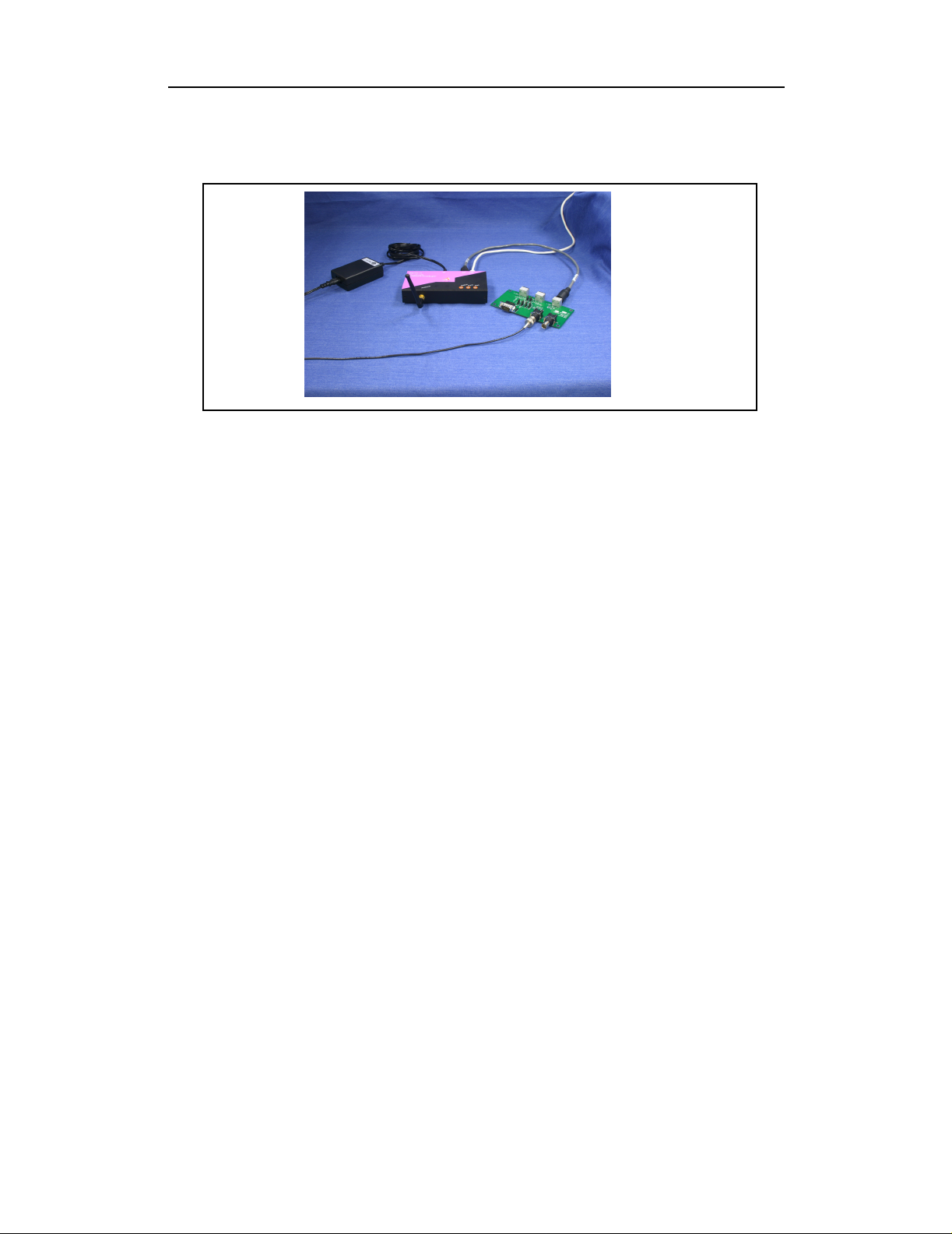
Connecting the Breakout Board
Merlin II with power supply (left) and Breakout board (right).
The photograph above shows a fully connected Merlin II.
The following connections can be seen: Left: Power supply connected to
the power port on the analyzer. Center: Mini DIN cable leading to Port 1
of the breakout board. USB cable leading to an offscreen PC. Right: BNC
cable leading from the Breakout board to an offscreen device on the left.
Configuring the Analyzer for the Breakout Board
To configure the analyzer for the breakout board, see section "Save External
Interface Signals" on page 68, and section "External Input Signals" on page
88.
16
Page 27
Merlin II Protocol Analyzer User’s ManualCATC SW Version 2.50
3. Updates
BusEngine and Firmware updates often need to be performed when you
update the Merlin II software. These updates can be performed
automatically or manually. Both processes are described.
3.1 Update Files
Update files are installed with the Merlin II software during the installation
procedure and reside in the local directory of the analyzer application.
During the update process, the files are taken from this location.
The following update files are provided with each release:
BusEngine - For updating the hardware logic (has an *.bin extension).
Firmware- For updating the platform firmware (has an *.hex extension).
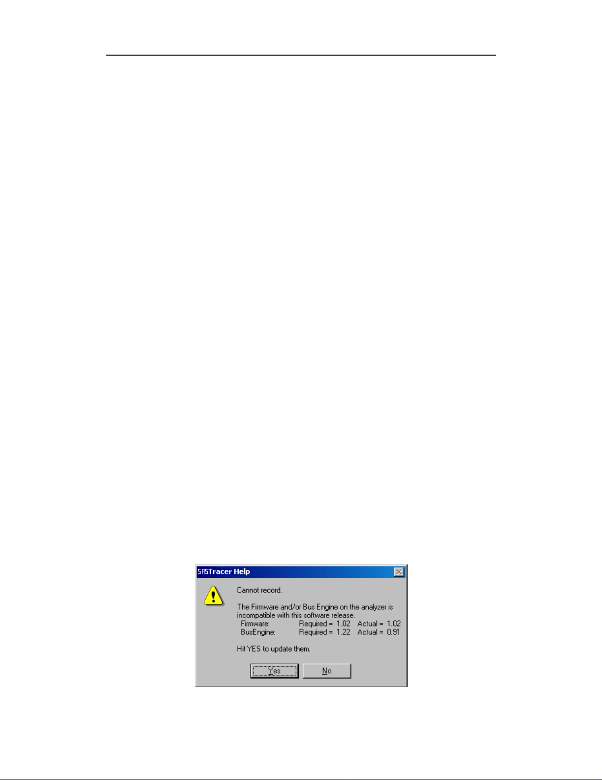
3.2 Automatic Updates
When you update the analyzer software, the software may become
incompatible with the BusEngine and Firmware. After the analyzer is
powered on, the analyzer will display an error message telling you that it
needs to update the Firmware and/or BusEngine. When you click OK, the
update process takes place automatically.
To update the BusEngine and/or Firmware, follow these steps:
Step 1 If needed, update the analyzer software, following the steps outlined
in "Software Updates."
Step 2 Turn on the analyzer.
Because the BusEngine and/or the Firmware ar e in compatib le with
the current analyzer software version, an error message appears
showing your current versions and indicating what versions you
need to install.
17
Page 28
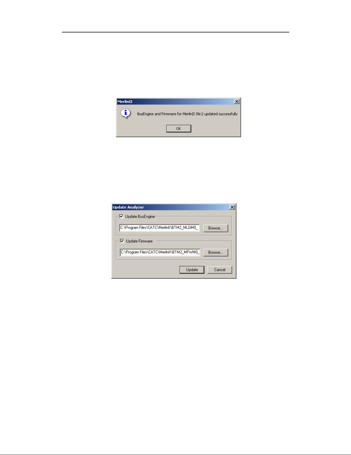
Step 3 Click Yes.
The update process begins.
When the update has finished, a message such as the following
appears and tells you that the update is complete. The example
below follows a BusEngine update.
Step 4 Click OK.
Manual Updates
If you prefer, you can manually update the Firmware, and/or BusEngine
through the 'Analyzer Setup' dialog. To do this follow these steps:
Step 1 Select from the menu: Setup > Update BE/FW ....
Merlin II Protocol Analyzer User’s ManualCATC SW Version 2.50
The Update Analyzer dialog box opens.
Step 2 Select the one of the entity that you want to update from the list.
Step 3 If needed, browse to the application directory to locate the Update
files.
Step 4 Click the Update button.
At this time, the application would start the update process. A
progress bar in the dialog would show the progress of the update
process.
Please note that in some cases this process can take several minutes
to complete.
Step 5 When a the application notifies that the update process is done, you
may need to cycle the analyzer's power to cause the program to take
effect, or you may need to unplug and then reconnect the USB cable
18
Page 29
Merlin II Protocol Analyzer User’s ManualCATC SW Version 2.50
between the analyzer and the computer to cause the new firmware
upgrade to take effect.
3.3 Software, Firmware, and BusEngine Versions
The Readme.html file on the installation CD and on the installed directory
on your hard drive. This file gives last-minute updates about the current
release. Included with each release are the most recent downloadable
images of the Firmware and the BusEngine.
Once the Merlin II has completed the self diagnostics and is connected to
the PC, you can check the latest version of the software and BusEngine.
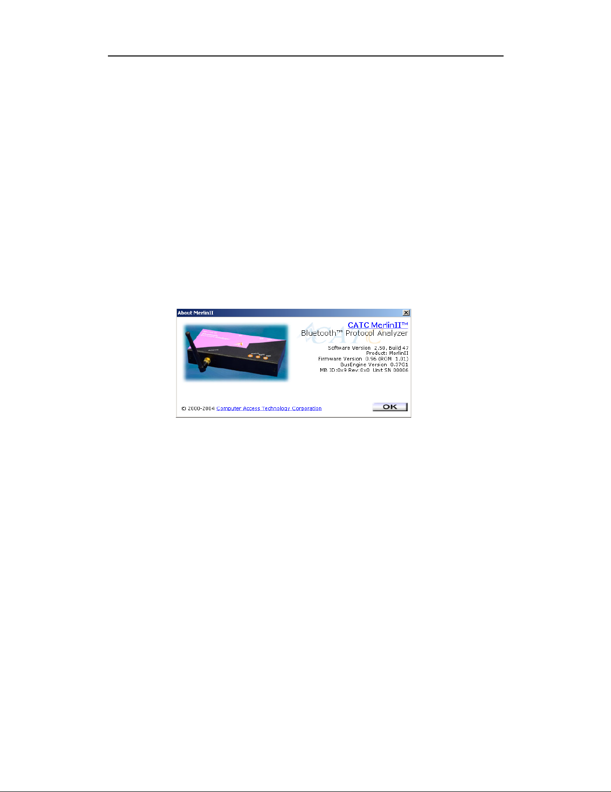
To check information about the current software, select
About Merlin II … from the Help menu.
The About Merlin II window appears.
About Merlin II details revisions of the following software and hardware:
• Software Version and Build Number
• Product Name
• Firmware Version
• BusEngine Version
• Unit Serial Number
Note When contacting CATC for technical support, please have available
all the revisions reported in the About Merlin II window.
3.4 Software Updates
When a new software release is available, it is posted on the Support page
of the CATC website at
www.catc.com/support.html.
The software is also available on CD from CATC.
19
Page 30

Merlin II Protocol Analyzer User’s ManualCATC SW Version 2.50
Updating from CD-ROM
To update the software from CD-ROM, follow these steps:
Step 1 Load the CD-ROM into the CD-ROM drive
Step 2 An install screen opens.
Step 3 Click Install Software and follow the onscreen instructions.
Updating from the CATC Website
Step 1 Open a web browser and navigate to www.catc.com.
Step 2 Find the latest released software version on the CATC website under
Support at the link shown at the top of the page.
If you are running the latest version of the software, no further
action is needed.
If you are not running the latest version.
Step 3 Download the software from the CATC website.
Step 4 If downloading from the web, unzip the files into your choice of
directory.
Step 5 Click Start, then Run, and browse to where you unzipped the files.
Step 6 Select the program named Setup and click Open.
Step 7 Click OK to run the Setup and begin the installation.
Step 8 Follow the on-screen instructions to complete the installation.
Step 9 Read the Readme file for important information on changes in the
release.
3.5 License Information
Licensing information for Merlin II can be viewed by selecting Display
Information from the Help menu. The License window provides
maintenance expiration and features data for Merlin II.
Updating the Software License
A License key is necessary to enable software maintenance.
A license is granted with the purchase of an analyzer. Thereafter, you must
renew your license if you wish to continue receiving support. You obtain a
new License Key from CATC. Once the License Key is obtained, follow
these steps to install it:
20
Page 31

Merlin II Protocol Analyzer User’s ManualCATC SW Version 2.50
Step 1 From the Help menu, select Update License. The Update License
dialog displays.
Step 2 Enter the path and filename for the License key or use the Browse
button to navigate to the directory that contains the License Key.
Step 3 Select the *.lic file, and then click Update Device.
21
Page 32

Merlin II Protocol Analyzer User’s ManualCATC SW Version 2.50
22
Page 33

Merlin II Protocol Analyzer User’s ManualCATC SW Version 2.50
4. Software Overview
4.1 The Main Display Windows
While some of the analyzer’s Main Display window options are familiar,
many contain options specific to the analyzer program.
Table 1: Main Display Pull-Down Windows
Menu Function
File
Open… Opens a file
Close Closes the current file
Save As… Saves all or a specified range of packets from the current file with a
specified name
Re-apply Encry pt i on
Settings ...
Print… Prints part or all of the current traffic data file
Print Prev
Print Setup… Sets up your current or new printer
Edit Comment… Creates or edits the Trace file comment fie ld
mport » Device List... Imports Device List file of previously identified devices & addresses.
I
Export » Packets to
Text (Packet View
Format)
Export » Packets to
CSV Text
Export
Streams
Last File Lists the last files that were opened
Ex
iew Produces an on-screen preview before printing
>>Audio
it Exits the Merlin II program
If a trace has been recorded with the wrong encryption settings, you
can enter the correct ones via the Devi ce L ist, then run File>
Re-apply Encryption Settings ... This command will open a Save As
dialog box for creating a new trace file usin g t he new settings.
Saves all or part of a trace to a text file
Saves all or part of a trace to a Comma Separated Values (CSV) file
suitable for viewing in a spreadsheet application
Saves audio data into a file. Presents options for setting the Audio
Source format, Output File format, Stream Direction, and Output
Sampling
Setup
Display Options Provides the control of various display options such as color, formats,
and filters.
R
ecording Options Opens a dialog box with checkboxes and drop-down menus for
setting up a recording.
Recording W
Update BE/FW Allows the operator to update the BusEngine and Firmware.
izard Starts a sequence of interactive dialog boxes that config ures Merlin II
for a recording. This utility provides an alternative to the Recording
Options dialog box.
23
Page 34

Merlin II Protocol Analyzer User’s ManualCATC SW Version 2.50
Menu Function
Connectors ... Opens a dialog box fo r the output connect or on the back of the
analyzer. There are two options:
Default Configuration - Causes the analyzer to output a low voltage
output signal for use by another device such as an oscilloscope. See
“External Input Signals” on page 88 for further explanation.
Output Radio Data - Causes the analyzer to output radio signal s
through External Output connectors. If you place your mouse pointer
over the Output Radio Data option, a tool tip will provide a detailed
explanation of this option’s function.
Record
Start Causes the Analyzer to begin recording Bluetooth activi t y.
Stop
Recording Mode Presents a drop-down menu with options for setting the analyzer's
T Neighborhood
B
Inquiry
Causes the Analyzer to stop recording.
recording mode :
Piconet Recording Mode -- Causes Merlin II to monitor and record
piconet traffic.
Recording Options, then uploads the data as a Trace file when the
recording is complete.
Inquiry Recording Mode -- Causes Merlin II to perform an inquiry to
detect and record Bluetooth devices within range. After comple ting
the recording, Merlin II uploads the trace to the PC and saves it as a
Trace file.
Displays Bluetooth Address & clock frequency for devices in range.
The expected Bluetooth clock frequency i s 3200 Hz +/- 250 ppm.
Merlin II records the traffic data as specified in the
Report
File Information Details such information about the recording as number of packets
and triggering setup.
E
rror Summary Displays an error summary of the current trace file & allows you to go
to a specific packet, and sav e th e error file to a uniquely named file.
Timing C
T
alculation Starts the calculator dialog for calculating various timing and
bandwidth parameters in the recording file.
raffic Summary Details the number an d type of packets were transf erred during the
recording, as well as message-level statistics.
Search
Go to trigger Positions the display to show the first packet that follows the trigger
event.
Go to
Packet/Message/
Protocol ...
Go to M
Go to » Enables quick searching for specific events using a cascade of pop-up
Find Allows complex searches.
Find N
Search Direction Allows you to specify a forward or backward search of a trace file.
arker » Positio ns the display to a previously marked packet.
ext Repeats the prev ious Find operatio n. Can also use F3 to find next.
Positions the display to the indicated packet, LMP/L2CAP message,
or Protocol Message (RFCOMM, TCS, or SDP protocols).
windows.
24
Page 35

Merlin II Protocol Analyzer User’s ManualCATC SW Version 2.50
Menu Function
View
Toolbars Presents a sub-menu with options for displaying/hiding the toolbars
and an option called Customize which allows the menus and toolbars
to be customized or reset to factory default.
tatus Bar Switches display of the Status Bar on or off.
S
Unhide Cells > Presents a menu of currently hidden cells. Allows you to unhides any
cells that were hidden through the Display Options dialog bo x (View
> Display Options > Color/Format/Hiding)
Zoom In
Zoom Out
rap Allows the display to wrap.
W
Device List
Real-time Statistics
Decoding
Assignments
L2CAP Connections Lists current L2CAP connections.
RFCOMM Channel
Assignments
L
evels Presents a menu of display levels. This menu replicates the
Profiles Presents a menu of profiles. Selecting a profile will cause the
Increases the size of the displayed ele ments.
Decreases the size of the display ed elements.
Displays a list of disc ov e r ed B lu et oo t h de vice s an d a llo w s yo u to ad d
and delete devices and security settings by selecting the device,
pressing the security button, and modifying the settings.
Opens a dialog box wi th a gr a p hic a l su mm a ry of the tr af fic currently
being recorded by the Analyzer. Real-time monitoring allows
continuous monitoring and displaying of traffic and related statistical
dada in a piconet. This proc es s e d da ta is disp layed in a set of
configurabl e graphs.
Lists current L2CAP decoding assignments.
Lists current RFCOMM assignments.
Decode/Display butto ns i n t he toolbar such as Packets, L2CAP, TCS
etc.)
analyzer to decode the protoco ls appropriate for the selected profile.
Window
New Window Switches display of the Tool Bar on or off.
ascade Displays all open windows in an overlapping arrangement.
C
ile Arranges multiple trace windows as a series of strips across the main
T
display area or as a series of side-by-side tiles.
Arrange Icons Arranges minimized windows at the bottom of the di splay.
W
indows Displays a list of op en windows.
25
Page 36

Help
Online Help Displays Help topic associated with current Merlin II window.
Help Topics... Displays online help.
Update License... Opens a dialog box for entering lice n s e ke y information for the
D
isplay License
Information...
A
bout Merlin II... Displays version information about Merlin II.
4.2 Toolbar
There are five toolbars in the Merlin II user interface toolbar. The Toolbar
buttons provide access to frequently-used program functions. Tool tips
describe icon functionality as the mouse arrow is moved over an item.
You display or hide toolbars by selecting View > Toolbars from the menu.
The sub-menu lists four toolbar names: Standard, Frequently Used,
Analysis, View Level, and Profiles.
Merlin II Protocol Analyzer User’s ManualCATC SW Version 2.50
analyzer.
Displays current license informat ion for the analyzer.
Standard Toolbar
Open file
Save As
Print Preview
Print…
Setup Record Options - presents options for setting up a recording.
Setup Display Options - presents options for formatting the display.
Setup Display Options - presents options for formatting the display.
Start Recording - starts a recording. The down arrow
gives you options for starting different types of
recordings: recording piconet, inquiry recording,
BTTrainer recording, or IUT:HCI recording.
26
Page 37

Merlin II Protocol Analyzer User’s ManualCATC SW Version 2.50
Stop Recording
Manually trigger the analyzer. Causes t he analyzer to stop recording
after the post-trigger buffer is filled.
Snapshot. Causes the analyzer to extract and display a portion of the
current recording into a new temporary window.
Insert marker. Inserts a marker into the trace.
Bluetooth Neighborhood. Performs an inquiry and then lists the local
devices that it discovered.
27
Page 38

Merlin II Protocol Analyzer User’s ManualCATC SW Version 2.50
"Frequently Used" Toolbar
Zoom In
Zoom Out
Wrap
Show/Hide Channel 1 Traffic
Show/Hide Channel 2 Traffic
Show/Hide Duplicated Traffic
Show/Hide Frequency Hops
Show/Hide Nulls & Polls
Show/Hide ID Packets
Show/Hide Voice (SCO) Packets
Show/Hide devices. Click the down arrow to open a menu with d evic e
addresses. Selecting a device address hides the device in the trace. This
button duplicates the functionality of the Hide Device options in the
Display Options dialog box.
Show/Hide Unassociated Tra f fic
Show/Hide HCI Traffic
Complex Find
Find Next
28
Page 39

Analysis Toolbar
Display Real time log
Display device list
File Information Report
Error Summary
Timing Calculations
Traffic Summary
Merlin II Protocol Analyzer User’s ManualCATC SW Version 2.50
Display Bus Utilization graph
Display Real-Time Statistics
View Level Toolbar
View Packet Level (Baseband)
View HCI Traffic
View/Hide LMP Message Level
View/Hide L2CAP Message Level
View/Hide SDP Message Protocol Level
View/Hide SDP Transaction Protocol Level
View/Hide TCS Protocol Level
29
Page 40

Merlin II Protocol Analyzer User’s ManualCATC SW Version 2.50
View/Hide RFCOMM Protocol Level
View/Hide OBEX Protocol Level
View/Hide OBEX Protocol Transaction Communications Level
View AT Commands Protocol Level
View/Hide HDLC Protocol
View/Hide PPP
View/Hide HCRP
View/Hide AVCTP
View/Hide AVDTP
View/Hide BNEP Protocol
View HID Protocol Layer
View IP Protocol Layer
View TCP Protocol Layer
View UDP Protocol Layer
View Profiles Toolbar
Profile buttons decode the protocols associated with a particular profile.
When you press a profile button, the Merlin II software will automatically
select for you the protocol buttons associated with that profile such as
RFCOMM and OBEX.
30
Page 41

Merlin II Protocol Analyzer User’s ManualCATC SW Version 2.50
Note: This toolbar is hidden on initial activation of the application. To
display this toolbar, select View > Toolbars > Profiles from the menu.
Decodes protocols for the GAP profile.
Decodes protocols for the S DAP profile.
Decodes protocols for the CI P profile.
Decodes protocols for the GAVDP profile.
Decodes protocols for the CTP profile.
Decodes protocols for the IN T profile.
Decodes protocols for the SPP profile.
Decodes protocols for the HP profile.
Decodes protocols for the DUP profile.
Decodes protocols for the FAX profile.
Decodes protocols for the LAN profile.
Decodes protocols for the SIM profile.
Decodes protocols for the OB EX profile.
Decodes protocols for the OP P profile.
Decodes protocols for t he FTP profile.
Decodes protocols for the SYNC profile.
Decodes protocols for the BI P profile.
31
Page 42

Decodes protocols for the A2DP profile.
Decodes protocols for the BI P profile.
Decodes protocols for the BI P profile.
4.3 Status Bar
The Status Bar is located at the bottom of the main display window.
Depending on the current activity, the bar can be divided into as many as
four segments. The figure below demonstrates the various displays in the
status bar.
Recording Progress
When you begin recording, the left-most segment of the Status Bar displays
a Recording Progress Indicator. The following figure displays the various
indications of the status bar:
Merlin II Protocol Analyzer User’s ManualCATC SW Version 2.50
Status Bar Position Definitions:
The following numbered definitions correspond to the number labels on the
above status bars.
1 Analyzer is connecting to the host machine.
2 Analyzer was disconnected from the host machine.
3 Analyzer is connected to the host machine.
32
Page 43

Merlin II Protocol Analyzer User’s ManualCATC SW Version 2.50
4 Analyzer is connected to the host machine and is an idle mode.
5 Analyzer is sy nchronized to a piconet with master device t hat has BD_Address
008037322FD9.
6 Analyzer is performing an inquiry (BT Neighborhood).
7 Analyzer is in the process of synchronizing to a piconet with slave dev ice that
has BD_Address 0080373 22F D8. The an al yzer is s et to us e the 'Page Sync &
Record' synchronization method, with master address set to 'any.
8 Analyzer is in the process of synchronizing to a piconet with master device
that has BD_Address 008037322FD9. No trigger connection received yet.
9 Analyzer is in the process of syn chronizing to a piconet with master device that
has BD_Address 0080371637B7. The analyzer is set to use either of the
synchronization methods (if the 'Page Sync & Reco rd' synchronization method
is used the master address is set to 0080371637B7).
10 Analyzer is recording the traffic of the piconet with master device that has
BD_Address 008037322FD9. The trigger condition was received.
11 Analyzer has finished uploading the recorded traffic.
As recording progresses, the Progress Indicator changes to reflect the
recording progress graphically:
• In the Progress Indicator, a black vertical line illustrates the location of the
Trigger Position you selected in Recording Options.
— Pre-Trigger progress is displayed in the field to the left of the Trigger
Position in the before-Trigger color specified in the Display Options.
— When the Trigger Position is reached, the pro gress indicator wiggles as it
waits for the trigger.
— After the trigger occurs, the field to the right of the Trigger Position fills
in the post-Trigger color specified in the Display Options.
— When recording is complete, the upper half of the progress indicator fills
in white, indicating the progress of the data upload to the host computer.
You should be aware of two exceptional conditions:
• If a Trigger Event occurs during the before-Trigger recording, the
before-Trigger color changes to the after-Trigger color to indicate that not all
the expected data was recorded pre-Trigger.
• When you click Stop before or after a Trigger Event, the Prog ress Bar ad justs
accordingly to begin uploading the most recently recorded data.
The Progress Bar fills with color in proportion to the specified size and
actual rate at which the hardware is writing and reading the recording
memory. However, the Progress Indicator is normalized to fill the space
within the Status Bar.
33
Page 44

Recording Status
During recording activity, the current Recording Status is temporarily
displayed in the next segment. When you activate the Record function, this
segment flashes one of the following messages (depending on the selected
Recording Options):
After recording stops,
To abort the upload process,
Merlin II Protocol Analyzer User’s ManualCATC SW Version 2.50
— Trigger?
— Triggered!
— Recording & Spooling
— Uploading
— The flashing message changes to Uploading data–x% done (x%
indicates the percentage completion of the data uploading process).
— The traffic data is copied to disk (over writing any prev ious version of this
file) using the default file name data.tfb or a new name specified in the
Recording options.
• Press Esc on your keyboard
When the data is saved, the Recorded Data file appe ars in the ma in displa y
window and the Recording Status window is cleared.
• If the recording resulted from a Trigger Event, the first packet following the
• If the recording did not result from a Trigger Event, the display begins with the
Analyzer Status
The third segment in the status bar displays ana lyzer status. The status will
display one of the following:
No Sync - the system is not synced to any piconet
Inquiring... - The system is performing an Bluetooth Inquiry
Inquiring (infinite) ...- The timeout is set to 0.
OR
Again click
You are prompted to choose whether to keep the partially u ploade d data o r to
throw it away.
Trigger (or the packet that caused the Trigger) is initially positioned second
from the top of the display.
first packet in the traffic file.
in the Tool Bar.
Sync [XXX]... - The system is attempting to synchronize to a piconet where
the device with BD_Address XXX is the master.
34
Page 45

Sync [XXX] - The system is synchronized to a piconet where the device
with BD_Address XXX is the master.
Rec [XXX] - System is recording the Bluetooth traffic of the piconet where
the device with BD_Address XXX is the master.
Received Signal Strength Indication (RSSI) - After the analyzer has
synchronized to the Bluetooth piconet under observation, an RSSI
measurement of the master’s transmission will appear in the status bar along
side of the Master’s address and the Sync/Rec status. The signal strength
readings will display as a value in the ra nge of -85 dBm t o -17 dBm. When
performing an inquiry, the status bar displays the RSSI measurement of the
responding devices.
The average RSSI measurement per device can be viewed in the Real Time
Statistics window. The RSSI measurement per packet can be seen in the
trace itself by expanding the Freq cells.
Search Status
The rightmost segment displays the current search direction: Fwd (forward)
or Bwd (backward).
Merlin II Protocol Analyzer User’s ManualCATC SW Version 2.50
4.4 Zooming In and Out
The Zoom In and Zoom Out buttons allow the trace to be displayed in a
larger or smaller format.
Zoom In
Zoom In increases the size of the displayed elements, allowing fewer (but
larger) packet fields per screen.
Click on the Tool Bar.
•
Zoom Out
Zoom Out decreases the size of the displayed elements, allowing more (but
smaller) packet fields per screen.
•
Click on the Tool Bar.
4.5 Tool Tips
Throughout the application, tool tips provide useful information.
To display a tool tip, position the mouse pointer over an item. The tool tip
displays in a short moment if present. Tool tips can also be found over the
Tool Bar and in areas of the packet view screen.
35
Page 46

Merlin II Protocol Analyzer User’s ManualCATC SW Version 2.50
4.6 Merlin II Analyzer Keyboard Shortcuts
Several frequently-used operations are bound to keyboard shortcuts.
Table 2: Keyboard Shortcuts
Key Combination Operation Key Combination Operation
Ctrl+O Open file Ctrl+P Print...
Ctrl+Home Jump to First packet Ctrl+End Jump to Last packet
Ctrl+F Search Forward Ctrl+B Search Backward
F3 Find Next Ctrl+L Search for Loss of Sync
Shift+I Goto ID packet Shift+R Goto Freq Hop packet
Shift+P Goto Poll packet Shift+N Goto Null packet
Shift+M Goto DM1 packet Shif t+F Goto FHS pac ket
Shift+1 Goto HV1 packet Shift+H Goto DH1 packet
Shift+3 Goto HV3 packet Shift+2 Goto HV2 packet
Shift+A Goto AUX1 packet Shift+V Goto DV packet
Shift+5 Goto DH3 packet Shift+4 Goto DM3 packet
Shift+7 Goto DH3 packet Shift+6 Goto DM5 packet
Shift+S Search for Soft Error Shift+E Search Error
36
Page 47

Merlin II Protocol Analyzer User’s ManualCATC SW Version 2.50
5. Recording Wizard
Recording Wizard is an interactive utility that presents a series of
user-friendly dialog boxes for setting up a recording session. Recording
Wizard serves as an alternative method of configuring the Recording
Options dialog box. When you are finished using the Wizard, you can view
your settings in the Recording Options window. By providing data to the
prompts in the Wizard’s dialog boxes, you configure Merlin II for a
recording session.
Starting Recording Wizard
To start the Recording Wizard,
• Click on the Tool Bar or select Recording Wizard under Setup on the
Menu Bar.
You see the Recording Options window:
The Recording Options window has three buttons marked Next, Back, and
Cancel that allow you to move forward or backward through the wizard or
to cancel the wizard.
To begin advancing through the wizard,
Click Next to see the options for the three types of recordings that the
•
Recording Wizard can make.
37
Page 48

Merlin II Protocol Analyzer User’s ManualCATC SW Version 2.50
The Wizard advances to the next screen which presents three options:
• I want to establish a new piconet and have Merlin II record traffic on that
piconet.
This option causes Merlin II to perform an Inquiry so it can discover
local devices and then establish a new piconet and record the piconet
traffic.
• I want Merlin II to record traffic on a piconet that has already been
established.
This option lets Merlin II record traffic from an already established
piconet.
• I am using Bluetooth Test Mode and want Merlin II to record traffic on
my test piconet.
This option lets Merlin II create either a single frequency ran ge recording
of a range that you specify or create a recording of a limited hop
frequency range consisting of 5 frequency hops.
5.1 Recording a Traffic on a New Piconet
The New Piconet option shown in the previous screen presents users with
the means of recording the traffic from a new piconet. This option will
cause a sequence of screens to prompt you for information such as the
piconet Master address.
38
Page 49

Merlin II Protocol Analyzer User’s ManualCATC SW Version 2.50
The following steps shows you how to configure Merlin II to record a new
piconet.
Step 1 From the screen shown in the previous screenshot, select the
first option: I want to establish a new piconet and have
Merlin II record traffic on that piconet, then press Next.
The following screen displays.
Step 2 Select Perform Inquiry Now, then press Next.
Selecting Perform Inquiry Now will cause Merlin II to perform a
General Inquiry and collect addresses and other details about local
Bluetooth devices. If you already have address information for your
Bluetooth devices you can choose Skip Inquiry. Choosing Skip
Inquiry will cause the Recording Wizard to advance to Step 6. If you
are not sure what option to select, choose Perform Inquiry Now.
39
Page 50

Merlin II Protocol Analyzer User’s ManualCATC SW Version 2.50
The following screen will display.
You will see two options:
• I want to search for all Bluetooth devices within range
This option will cause Merlin II to search for all Bluetooth devices that
are in range and ready to transmit and receive data (i.e., in Inquiry Scan
Mode)
• I want to search only for devices corresponding to the following
(hexadecimal) DIAC:
This option will cause Merlin II to search for the class of devices tha t you
specify in the DIAC text box. DIAC stands for Device Inquiry Access
Code. Values are entered in hexadecimal format. You can get DIAC
values from the Bluetooth Specification.
Step 3 Select the first option: I want to search for all Bluetooth devices
40
Page 51

Merlin II Protocol Analyzer User’s ManualCATC SW Version 2.50
within range, then press Next. The following screen will display.
You will see two options:
Step 4 In the text box, enter the length of time you want Merlin II to search
for nearby devices.
The default value is 11. If you do not sure what time value to enter, use
the default value.
Step 5 Press Next.
Before the Inquiry, Merlin II tests the hardware connection. In the case
of failure, the following screen will display.
Clicking OK will close the message box.
41
Page 52

Merlin II Protocol Analyzer User’s ManualCATC SW Version 2.50
If Merlin II passes the hardware test, it will search for devices. The
Recording Wizard will display a progress bar and a message telling you
that a search is under way:
If no device is found, the Recording Wizard will display the following
screen:
42
Page 53

Merlin II Protocol Analyzer User’s ManualCATC SW Version 2.50
If devices found, the Recording Wizard will display the following
screen:
Step 6 Press Next.
The following window will display:
Step 7 Select from the drop-down menu the hexadecimal address for your
Master device. If you do not see your device’s address, you may
type it into the text box yourself.
43
Page 54

Merlin II Protocol Analyzer User’s ManualCATC SW Version 2.50
The following window will display:
Step 8 Select from the drop-down menu the hexadecimal address for your
slave device into the box labeled Piconet Slave Address. If you do
not see your slave’s address, you can type it into the box.
Step 9 Press Next.
The following screen will display.
This screen displays the settings you selected.
44
Page 55

Merlin II Protocol Analyzer User’s ManualCATC SW Version 2.50
The Advanced button on the right will open the Recording Options
dialog box shown below. Thi s screen will show the set tings you selected
through the Recording Wizard have been applied to the Recording
Options dialog.
Step 10 Press Next to advance the Recording Wizard to the next screen.
The following screen displays:
Merlin II pages the Master and if specified in Step 8, the Slave devices.
45
Page 56

Merlin II Protocol Analyzer User’s ManualCATC SW Version 2.50
If Merlin II is unable to complete its pages, the following screen will
display:
If Merlin II is able to complete its pages, it will enter into a synchronizing
state and then wait for you to create the piconet. During this waiting
period, Merlin II will display the following screen:
46
Page 57

Merlin II Protocol Analyzer User’s ManualCATC SW Version 2.50
Once you have created the piconet, Merlin II will synchronize to the
piconet and begin recording. During the recording, Merlin II will display
the following screen:
At the completion of the recording, Merlin II will display the following
screen:
You can repeat the recording by pressing the Repeat button.
Step 11 To close the wizard, press the Close button.
47
Page 58

Merlin II Protocol Analyzer User’s ManualCATC SW Version 2.50
The wizard will close and your trace will display.
5.2 Recording an Existing Piconet
Using Recording Wizard to record an existing piconet i s similar to recording
a new piconet. The main difference is that you will be asked if your Master
device can support multiple slave devices and whether it can respond to
pages once it has created a piconet with another device.
Step 1 To start the Recording Wizard, press or select Setup >
Recording Wizard from the menu.
48
Page 59

Merlin II Protocol Analyzer User’s ManualCATC SW Version 2.50
The Recording Wizard introductory page will open:
Step 2 Press Next to advance to the next screen.
You will see three choices:
Step 3 Select the second option: I want Merlin II to record traffic
on a piconet that has already been established.
Step 4 Press Next.
49
Page 60

Merlin II Protocol Analyzer User’s ManualCATC SW Version 2.50
You will see two choices:
Step 5 Select Perform Inquiry Now.
You will see two choices:
Step 6 Select the first option: I want Merlin II to search for all
Bluetooth devices within range.
If you want to limit the inquiry to a class of devices, select the second
option and enter the hexadecimal value for the device class in the text
box.
50
Page 61

Merlin II Protocol Analyzer User’s ManualCATC SW Version 2.50
Step 7 Press Next.
The following screen will appear:
Step 8 If you want to change the search duration, type in a new
value into the text box. Otherwise, use the default value (20
seconds), then press Next.
If Merlin II cannot detect other devices, the following message will
display:
51
Page 62

Merlin II Protocol Analyzer User’s ManualCATC SW Version 2.50
If Merlin II passes the hardware test, it will then goes onto conduct a
General Inquiry to locate local Bluetooth devices.
If Merlin II finds Bluetooth devices, it will display the following
message:
Check the Device List to see if Merlin II foun d all of the devices in y our
piconet. If you feel that the list is incomplete, you can close this window
and press the button marked Repeat. This will cause Merlin II to repeat
the General Inquiry and recollect information on local Bluetooth devices .
52
Page 63

Merlin II Protocol Analyzer User’s ManualCATC SW Version 2.50
Step 9 Press Next to advance to the next screen.
The following screen will prompt you for the Master device’s address.
The address can be selected from the menu or typed into the box:
Step 10 Select or type in the Master device’s address into the box
next to the label Piconet Master Address.
Step 11 Press Next.
The following screen will display. This screen asks you which of the
following two options apply to your Master device. For some devices,
both options will apply.
You can select either or both options. They are not mutually exclusive:
53
Page 64

Merlin II Protocol Analyzer User’s ManualCATC SW Version 2.50
If the Master supports inquiries while in a connected state, s elect the first
option. This will set Merlin II to use the 'Sync & Record' mode in its
attempts to synchronize to the Master. This will also cause the wizard to
skip to step 8.
If the Master can support piconets with multiple slaves, select the second
option. If you select this box alone (i.e., you leave the first box
unchecked), Merlin II will use the 'Passive Sync & Record' mode to
synchronize to the Master. The wizard will then advance to Screen 8*.
If the first checkbox was selected, Merlin II will use 'Sync & Record' no
matter what was set in the second box.
Step 12 If you want to skip the Master verification, put a check in the
box. If you are in doubt, leave the box unchecked.
If you selected only the second option in Step 12 (=’Passive Sync &
Record’), the following screen will display.
This screen asks you for the address of the Page Target device -- which
in this case is Merlin II. Since the devices in your piconet are not able to
respond to inquiries, Merlin II will not be able to page the devices and
join the piconet. Instead, you will assign Merlin II an address here in
this screen, then direct your piconet Master device to connect to Merlin
II. The Master will attempt to connect to Merlin II and therein give
Merlin II the information it needs to record the Master and slav e devices.
Step 13 Type in an address of your choosing for Merlin II (= Page Target).
You are making up an address for Merlin II that the Master will use to try
to connect to Merlin II.
54
Page 65

Merlin II Protocol Analyzer User’s ManualCATC SW Version 2.50
Step 14 Press Next
Merlin II will then display your current settings.
The Advanced button will open the Recording Options dialog box
shown on page 45 and described in detail in Chapter 7.
Step 15 Press Next to begin the recording.
If the Merlin II hardware is not ready or connected or is in the pr ocess of
booting up, the following information message box will display:
Step 16 If the above information box opened, press OK to close it.
55
Page 66

Merlin II Protocol Analyzer User’s ManualCATC SW Version 2.50
The following dialog box will display:
Step 17 Press Retry or Back to re-attempt the process.
If the hardware failure described above do not occur, Merlin II will
conduct an inquiry. The screen will show that Merlin II is going to
attempt a recording in either ’Passive Sync & Record’ mode as shown
below or in ’Sync & Record’ mode depending on the options you
selected in Step 15.
Step 18 If you are recording in ’Passive Sync & Record’ mode, you will
need to direct your Master device to attempt a connection to Merlin
II. This will provide Merlin II with the information it needs to
56
Page 67

Merlin II Protocol Analyzer User’s ManualCATC SW Version 2.50
record the piconet.
Once Merlin II has the information it needs, it will begin recording. The
following screen will display:
The recording will end following a trigger event or when y ou press Stop
Recording button on the screen shown above or when you press the
button on the toolbar.
Step 19 When finished, press Close to close the Recording Wizard.
5.3 Recording in Test Mode
A Test Mode recording allows you to limit the frequency hopping range that
Merlin II will record. Two Test Modes are available: Reduced Hopping
Mode and Single Frequency Mode. Reduced Hopping Mode limits Merlin
II’s recording to the five frequency hops that are described in the Bluetooth
Specification. Single Frequency Mode limits Merlin II’s recording to a
single frequency range that you specify in the Recording Wizard.
Recording in Reduced Hopping Mode
To record in Reduced Hopping Mode, perform the following steps:
Step 1 Start the Recording Wizard by either pressing the button
or selecting Setup > Recording Wizard from the menu.
The Recording Wizard greeting screen will open.
57
Page 68

Merlin II Protocol Analyzer User’s ManualCATC SW Version 2.50
Step 2 Press Next to advance to the Recording Type screen.
The following screen will display:
Step 3 Select the third option: I am using Bluetooth Test Mode
and want Merlin II to record traffic on my test piconet.
Step 4 Press Next.
The following screen will display:
58
Page 69

Merlin II Protocol Analyzer User’s ManualCATC SW Version 2.50
Step 5 Select the option Reduced-hopping mode, then press Next.
The following screen will display:
Step 6 Select the address for your piconet’s Master device from the
drop-down menu. If you prefer, you can type in the address
into the box.
Step 7 Press Next.
The following screen will display. This screen will show the current
settings for the recording:
59
Page 70

Merlin II Protocol Analyzer User’s ManualCATC SW Version 2.50
The Advanced button will open the Reco rdi n g Opti ons dial og box . See
Chapter 7 for details on the Recording Options dialog box.
Step 8 Press Next to begin the recording.
The following screen will display:
Step 9 When the recording finishes, the following screen will display.
You can repeat the recording by pressing the Repeat button.
Step 10 To close the wizard, press Finish.
60
Page 71

Merlin II Protocol Analyzer User’s ManualCATC SW Version 2.50
5.4 Recording in Single Frequency Mode
Step 1 In the Recording Type window, select the third radio button
and click Next.
Step 2 In the Frequency Hopping Mode, window select the
Fixed-Frequency Mode radio button, enter the appropriate
values in the text boxes, and click Next.
Step 3 In the Master Device address box, enter the BD Address for
61
Page 72

Merlin II Protocol Analyzer User’s ManualCATC SW Version 2.50
your Master Device.
Step 4 Press Next.
Step 5 Press Next. Merlin II then synchronizes with the Master
62
Page 73

Merlin II Protocol Analyzer User’s ManualCATC SW Version 2.50
device and begins recording.
63
Page 74

Merlin II Protocol Analyzer User’s ManualCATC SW Version 2.50
64
Page 75

Merlin II Protocol Analyzer User’s ManualCATC SW Version 2.50
6. Recording Options
While the Recording Wizard provides a "walk through" process for setting
the recording options, you can get a more detailed view and set more
parameters through the "Recording Options" dialog box. The Recording
Options dialog box presents all of the settings needed to make a recording.
Once you have selected your recording options, you then select the
recording mode by clicking the down-arrow on the Record button and
selecting from the two mode options: Piconet and Inquiry. Merlin II will
then use the relevant Recording Options for the selected mode. For
example, if you select Piconet recording mode, Merlin II will use the
options from the Piconet page in the Recording Options dialog box.
6.1 Recording Modes
Pressing the down-arrow on the Record button displays a menu with two
Recording Modes:
Selecting one of these modes tells the analyzer what sets of Recording
Options it should use when you begin a recording.
Note: Selecting a Recording Mode from the menu does not cause the
analyzer to begin recording. To begin recording, you must press the
Recording button itself.
Piconet recording
Selecting Piconet, configures Merlin II to record piconet traffic using the
parameters set in the Piconet page in the Recording Options dialog box.
When you begin recording in this mode, Merlin II will to try to synchronize
to a piconet that matches the Piconet parameters set in the Recording
Options. The recorded traffic is captured off-the-air.
Inquiry recording
This mode configures Merlin II to record Inquiry traffic. When setting the
Merlin II to Inquiry recording, the system is ready to perform a Bluetooth
'General' or 'Dedicated' inquiry, according to the parameters specified in the
'inquiry' page of the Recording Options. The recorded traffic would consist
the transmitted packets as well as the responses received from Bluetooth
devices in the area.
65
Page 76

Merlin II Protocol Analyzer User’s ManualCATC SW Version 2.50
UT:HCI mode
Configures the system to exclusively record HCI traffic from IUTs. This
recording mode bypasses the analyzer: HCI traffic from the IUT is recorded
directly by the analyzer software without going through the analyzer. This
means that you can record HCI traffic even if the analyzer is not turned on.
To record HCI traffic, first enable the recording of HCI traffic from IUTs.
You do this in the HCI page of the Recording Options dialog. Then set the
recording mode to something other than IUT:HCI. If you want to prevent
the recording of HCI traffic from IUTs, disable it in the HCI page of the
Recording Options dialog.
6.2 Opening the Recording Options Dialog Box
To open the Recording Options menu, click on the Tool Bar or select
Recording Options under Setup on the Menu Bar.
You see the Recording Options window. By default, the Piconet options
page displays:
66
Page 77

Merlin II Protocol Analyzer User’s ManualCATC SW Version 2.50
You will need to set options for each of the Recording Options pages.
Generally, it is best to begin with the General and Piconet pages where you
can set the type of recording, and then move on to the Events and Actions
pages where you can set triggering events.
6.3 Recording Options - General
The General page controls the length of a recording and how it begins and
ends. It is shown in the previous illustration. The General page display four
boxes marked Recording Type, Buffer Size, Trigger Position, and Options.
Recording type
The Recording Type box presents options that control how
Merlin II begins and ends a recording. The options are:
Snapshot, Manual Trigger, and Event Trigger.
Snapshot
A Snapshot is a fixed-length recording whose size is determined by the
"Buffer Size" box in the Recording Options dialog or by a manual click of
the Stop button. Recording begins by clicking on the
Tool Bar and ends when either the selected buffer size is filled or you press
the Stop button.
Manual Trigger
A Manual Trigger recording is a one that is manually begun and ended.
Recording is begun by pressing on the Tool Bar.
Recording continues in a circular manner within the limits set by the buffer
size. Recording ends when is clicked on the Tool Bar or the Trigger
button is pressed on the analyzer's front panel. If you press the Trigger
button, recording will continue until the post-trigger memory has been
filled.
Event Trigger
An Event Trigger recording is one that uses an event trigger to end the
recording. Before recording begins, you define the event trigger in the
Trigger Options dialog box. You begin the recording by clicking
manner within the limits set by the buffer size. Once the trigger event
occurs, some post-trigger recording occurs, then the recording ends.
Note In this mode, the recording can be stopped manually in the same way as for
Options
The Options box contains two options:
on the Tool Bar. Recording continues in a circular
"manual trigger" mode.
67
Page 78

Merlin II Protocol Analyzer User’s ManualCATC SW Version 2.50
Beep When Trigger Occurs
Will cause the PC to be ep when a tri gger even t
has occurred.
Save External Interface Signals
Will enable Merlin II to record input signals from a breakout board as fields
in a trace.
Buffer Size
The Buffer Size box has a slide bar for adjusting the
recording buffer size from 0.4 megabytes to 512
megabytes.
The Recording Type option determines how this buffer is used. Although
there are 512 megabytes of physical memory in the analyzer, the efficiency
of the recording ranges from 2:1 to 4:1 ratios of physical memory to actual
Bluetooth traffic. Shorter Bluetooth packets yield a less efficient recording.
The non-traffic portion of physical memory is utilized for control and timing
information.
Note The scale is not linear and affords more granularity in the smaller buffer sizes.
Trigger Position
The Trigger Position slide bar sets the amount of
post-trigger recording that Merlin II will perform. It
also allows adjustment of the location of the trigger
within the defined buffer. You can adjust the
Triggering Position between 1 and 99% post-Trigger.
Trigger Position is available only when Manual Trigger or Event
Trigger is selected as Recording type.
As an example, if the buffer size is set to 16MB, then for the following
Trigger Position settings, the amount of pre- and post-Trigger data is
• 95% post-triggering: 0.8MB pre-trigger, 15.2MB post-trigger
• 75% post-triggering: 4MB pre-trigger, 12MB post-trigger
• 50% post-triggering: 8MB pre-trigger, 8MB post-trigger
• 25% post-triggering: 12MB pre-trigger, 4MB post-trigger
• 5% post-triggering: 15.2MB pre-trigger, 0.8MB post-trigger
Note When a Trigger occurs, recording continues until the post-Trigger amount of the
buffer is filled.
68
Page 79

Merlin II Protocol Analyzer User’s ManualCATC SW Version 2.50
Debug
Enable CATC debug file
Checking this box enables the creation of a file that can be used by CATC
Support to aid in debugging. This option should always be disabled unless
you are requested to enable it by CATC personnel.
6.4 Recording Options - Piconet
The Recording Options dialog box has two pages for configuring how
Bluetooth traffic is recorded: Piconet, which configures piconet recording
sessions, and Inquiry which configures inquiry recording sessions.
For recording in Piconet mode, the Piconet page lets you specify the type of
piconet you will be recording and how Merlin II should synchronize and
record the piconet.
Frequency Hopping
Stay with Basic Hopping - Configures the probe to use the Basic Hopping
sequence as defined by the Bluetooth 1.1 specification.
Follow AFH - Configures the probe to use the Adaptive Frequency Hopping
sequence as defined by the Bluetooth 1.2 specification.
69
Page 80

Merlin II Protocol Analyzer User’s ManualCATC SW Version 2.50
Set... - Opens a dialog box for selecting the channels you would like Merlin
II to use.
LT_ADDr to Follow: Select devices to be followed.
Start with Pr ed ef in ed C h ann el M a p: Tel ls Merlin II whether
to use the selected channel map from the table. Select an AFH
sequence from the list, check Start with Predefined Channel
Map, then click OK.
Add ...: Opens a dialog box for selecting multiple channels. You
can shift-click or control-click to select or deselect multiple
channels. Add a name to the box marked Name and then click OK
to close the dialog box and keep your selection.
Edit ...: Opens the dialog box shown above and lets you change the
current settings.
Delete: Deletes the selected AFH sequence.
70
Page 81

Sequence
The Sequence field presents a drop-down menu with choices for the
Hopping Sequence Standard:
Merlin II Protocol Analyzer User’s ManualCATC SW Version 2.50
• 79 Hops Standard - Sets the analyzer to track
regular piconet traffic with 79 channels
hopping scheme.
• Reduced Hop - Used for test-mode recording.
Restricts Merlin II to five hop frequencies defined in the test
mode specification of the Bluetooth Specification. When
Reduced Hop or Single Frequency is selected, the Sync method
is set to Test Mode and cannot be modified by the user.
A typical test-mode setup consists of a device under test (DUT)
and a tester. In this hop sequence the devices are set to hop on a
limited set of five frequencies. When recor ding in this mode, the
analyzer does not use any of the Synchronization methods and
the options under Synchronization become grayed out.
• Fixed Frequency - Allows the transmit and receive frequency
ranges to be specified. This mode is used for test mode recording
where the tester and DUT are tr ansmitting and rec eiving on fixed
frequencies.
Enter values into the two text boxes to the set the transmit and
receive frequency ranges:
• DUT Xmit Freq, MHz (+2402) – Allows the setting of the
transmit signal for the Device Under Test
• DUT Recv Freq, MHz (+2404) – Allows the setting of the
receive signal for the Device Under Test
When Fixed Frequency is selected, the Sync method is set to
Test Mode and cannot be modified by the user.
Synchronization Method
Configures how the analyzer synchronizes to
the piconet under observation. There are three
methods of synchronization:
Sync and Record - Causes the analyzer to
perform a general inquiry, acquire the Master’s address and clock
information, and then begin recording.
71
Page 82

Merlin II Protocol Analyzer User’s ManualCATC SW Version 2.50
In this method, only the master address has to be specified. The analyzer
performs a general Inquiry operation to learn the Master’s hop frequency
and clock information through FHS packets. Once the FHS packet of the
specified piconet master is found, the analyzer begins recording using the
frequency hop sequence derived from the FHS information of the piconet
master.
Passive Sync & Record - In this method, both the master and paged target
addresses have to be specified. When the analyzer attempts to synchronize
to a piconet, it enters Inquiry Scan and awaits an inquiry from the device
specified in the 'Master Address' field. When the master performs an inquiry
the analyzer responds. Once the analyzer receives an FHS packet from the
specified piconet master (through paging), the analyzer begins recording
using the frequency hop sequence derived from the FHS information of the
piconet master.
Passive Sync and Record is used with established piconets or private device
networks.
Used in situations where the Master device and slave devices do not support
Inquiry Scan mode.
Page Sync & Record - This is the recommended method of recording. In
this synchronization method, the page target address has to be specified
while the master address is optional. Page Sync and Record should be
implemented before a piconet is established.
When the analyzer attempts to synchronize to a piconet using this method,
it first performs a General Inquiry operation, searches for incoming FHS
packets for the access code for the specified 'Page Target/Slave'. After the
FHS packet of the specified slave is found, the analyzer waits for the master
to begin paging the slave device. Once the paging process completes, the
analyzer begins recording using the frequency hop sequence derived from
the FHS information of the piconet master (captured during the paging
process). In this Method, the master device can be a specific one (in which
case its address should be explicitly selected in the 'Master Address' field)
or can be any device (in which case the 'any' entry should be set in 'Master
Address' field).
Test - This mode is automatically selected when one of the 'Fixed' or
'Reduced' hopping sequences has been selected. In this mode only
Test-mode Bluetooth traffic of a setup with the master device specified in
the 'Master Address' can be recorded.
72
Page 83

Merlin II Protocol Analyzer User’s ManualCATC SW Version 2.50
Recording When Already Synchronized
If the analyzer were already synchronized to a piconet, it will not try to
re-synchronize to the piconet that is defined in the Recording Options.
Instead, it will immediately start the recording using the frequency hop
sequence from the last recording operation. This results in shorter response
time until the actual recording is started.
The analyzer will attempt to synchronize only in the following:
• The hopping sequence setting was modified from the last
recording.
• The 'Force Re-Synchronization' flag is checked.
Master and Page Target Menus
To the right of the Sync Method menu are two menus which let you select
or enter address for the devices in the piconet:
• Master Address - Presents a drop-down list of Master devices
found previously. It also displays an option called Any which is
used in Page Sync and Record to tell the analyzer to synchronize
with any Master responding to the specified Page Target/Slave
address.
• Page Target -- Presents a drop-down list of Page Target devices
found previously. You can also enter address values in this box.
Between the two text boxes is the following button:
• - Swaps the Master and Page Target addresses.
When to Use the Different Piconet Recording Modes
Page Sync & Record is the preferred option and should be used whenever
possible. If Page Sync & Record can not be used, then Sync & Record
should be used. Passive Sync and Record should be used only if the first
two options can not be used.
Sync & Record
Sync and Record works just like "Page Sync and Record" except that Merlin
II takes its sync data directly from the Master instead of the Slave devices.
With Sync and Record, Merlin II conducts a General Inquiry to get hop
frequency and clock information from the Master. Merlin II then waits to
detect piconet traffic from the Master device’s piconet. When the piconet is
established, Merlin II is able to synchronize to the Master and begin
recording. In contrast to "Page Sync and Record", "Sync and Record" can
be run with or without an established piconet.
73
Page 84

Merlin II Protocol Analyzer User’s ManualCATC SW Version 2.50
Note This mode can only be used to find master devices that support Inquiry Scan.
To perform a "Sync and Record", follow the steps below:
Step 1 Turn on the Bluetooth devices under observation, and set up the
master device so it is ready to respond to Inquiry scan. For a typical
recording, ensure that the Master and Slave device(s) are not yet
connected.
Step 2 In the Modes tab under Recording Options, enter the Master
Device’s address.
Step 3 Start Merlin II recording by pressing the
Record button on the toolbar.
Step 4 When the analyzer is able to Sync up to the Piconet Master Clock,
the Green Sync LED in the Merlin II front panel will start
blinking.
Step 5 Establish connection between the Bluetooth devices under analysis.
Step 6 When Merlin II senses Pic onet traffic, the Green Sync light goes ON
solid, recording starts and the status bar in the bottom of the analyzer
screen shows activity.
Recording may be stopped manually or when the recording buffer is filled.
Note After the Sync light starts blinking, a connection between the Bluetooth
devices should be established within one (1) minute.
Passive Sync & Record
Passive Sync and Record is used in situations where the Master device and
slave devices do not support Inquiry Scan mode. When selected, Merlin II
enters Inquiry Scan and Page Scan mode and waits for a page from the
Master device. When the piconet Master pages Merlin II, Merlin II obtains
the information necessary for synchronization and then attempts to
synchronize to the piconet controlled by that Master.
"Passive Sync and Record" is designed to be used with established piconets
or private device networks.
Running "Passive Sync and Record" with Established Piconets
For most situations, "Passive Sync and Record" will be run after a piconet
has been established. The steps are as follows:
Step 1 Establish a connection between two or more Bluetooth devices.
74
Page 85

Merlin II Protocol Analyzer User’s ManualCATC SW Version 2.50
Step 2 Under General Recording Options, select "Passive Sync & Record."
Step 3 Under the Modes tab in Recording Options, enter the address for the
piconet’s master device.
Step 4 Make up an address for Merlin II and enter it into the Page Target
address in the Modes tab in Recording Options. Make sure you do
not select an address for any other local device.
Step 5 Press the record button on the toolbar in Merlin
II to start a recording session.
Step 6 If necessary, have Master "discover" Merlin II through a General
Inquiry.
Step 7 From the Master device, initiate a page to Merlin II address. This
action will enable Merlin II to synchronize to the piconet. However,
the analyzer will not complete the page sequence from the Master.
This will cause the Master to time out in this request.
Step 8 At the end of this sequence, the green Sync light will go on solid,
recording will begin and activity will be di spla yed on the sta tus bar
in the bottom of the analyzer screen.
Running "Passive Sync and Record" with Private Device Piconets
Because private device networks do not allow other devices to join the
network, Merlin II needs to temporarily assume the identity of a slave in the
network in order to join that network. To do this requires disabling the slave
and beginning the operation without an established piconet. The following
steps show the process.
Step 1 Turn the Master device on and the slave device off. You need the
slave device turned off so that Merlin II can take its place in the
piconet.
Step 2 Enter the slave’s address into Merlin II’s "Page Target" field in the
Modes tab in the Recording Options dialog box.
Step 3 Run "Passive Sync and Record." The Master will then page the
slave’s address and Merlin II will be able to sync.
Step 4 When Merlin II synchronizes to the Master, turn the slave back on.
When the Master re-pages the address the slave is admitted into the
private network. Since Merlin II is passive in this mode, the slave
and Merlin II do not conflict over the shared address. Merlin II is
75
Page 86

then able to record the traffic between the Master and slave.
Page Sync & Record
"Page Sync and Record" is the recommended method of recording. "Page
Sync and Record" should be implemented before a piconet is established.
This mode causes Merlin II to perform a General Inquiry and collect sync
information from the specified slave device when it responds. Merlin II
then waits for the Master to begin paging the Slave devices. When paging
begins, Merlin II synchronizes to the Master and begins recording.
Note In order for this mode to work, the intended Slave must support "inquiry scan".
The following steps describe the simplest way to use this mode:
Step 1 Place both the "intended master" as well as its first "intended slave"
into inquiry scan mode.
Step 2 Have Merlin II perform a General Inquiry. You do this by pressing
the BT Neighborhood button
Merlin II Protocol Analyzer User’s ManualCATC SW Version 2.50
Step 3 After the General Inquiry completes, the addresses will populate the
menus marked Master Device and Page Target . Select or enter the
addresses for both your Master Device and Page Target.
Step 4 Click OK at the bottom of the window to close the Recording
Options dialog box.
Step 5 Press the button found on Merlin II’s
toolbar. After approximately 11 seconds, the "SYNC" light
on the front of Merlin II will begin to flash, meaning that
Merlin II has acquired all the information it needs to fully
synchronize with the piconet about to be established. At this
point, you should establish the piconet using the devices
previously defined as master and slave.
Note Inquiry Timeout is configurable (0 to 80 seconds) in the Recording Options
General page.
Step 6 When the piconet is established, the "Sync" light on the front of
Merlin II will change from flashing to solid, indicating that Merlin
II is fully synchronized to the piconet and is currently recording all
traffic within that piconet.
76
Page 87

Merlin II Protocol Analyzer User’s ManualCATC SW Version 2.50
Note If the "sync" light on the front of Merlin II does not change from
flashing to solid it means that Merlin II did not synchronize with the
piconet when it was established.
Loss of Sync Timeout (1-30 secs)
This value specifies the amount of time that Merlin II will wait for piconet
traffic before determining that synchronization has been lost.
Force Re-synchronization
"Force Re-Synchronization" forces Merlin II to re-synchronize at the
beginning of each "Sync & Record," "Passive Sync & Record," or "Sync &
Record" operation. By default, "Force Re-Synchronization" is disabled
(i.e., unchecked).
Unchecking the "Force Re-Synchronization" checkbox tells Merlin II to use
its existing data on Bluetooth devices, thereby bypassing the
synchronization process and saving a few seconds from the beginning of the
trace. If you know that Merlin II’s data is correct, you can uncheck this
checkbox and cause Merlin II to try to use the existing data. If the data is
incomplete or incorrect, however, Merlin II will automatically perform a
refresh.
To examine Merlin II’s Bluetooth data, open the Device List (View >
Device List).
Show Paging Traffic
Show Paging Traffic causes Merlin II to capture paging traffic between the
Master and Page Target devices. This option is used only with Page Sync
and Record Mode.
Follow Anonymity
Allows Merlin II to follow devices that are using anonymity mode.
Anonymity mode is an addressing mode in which devices are assigned
Bluetooth addresses based on a pseudo-random value. Anonymity mode is
defined in the Bluetooth 1.2 specification.
77
Page 88

Advanced ...
The Advanced button opens a dialog box with additional
piconet settings:
Merlin II Protocol Analyzer User’s ManualCATC SW Version 2.50
Follow Master/Slave Switch
If enabled, this option allows Merlin II to follow a role switch between a
Master and Slave. This capability allows Me rlin II to ke ep track of cha nges
in a device’s role when it changes from one role to another.
Merlin II is able to follow a role change by listening to the Slave device’s
Bluetooth clock and hop frequency as soon as it becomes a Master.
Match Clock Rate
Match Clock Rate is a useful option if the Master device’s clock is
inaccurate. Match Clock Rate causes Merlin II to do a General Inquiry to
determine the Page Target's clock rate prior to synchronizing to the piconet.
If unchecked, Merlin II will begin piconet synchronization without first
doing a General Inquiry.
This option only works with Page Sync and Record mode.
Timeout (0-80 secs)
Default value for Inquiry Timeout is 20 seconds.
Correlation Value (33-64)
This value tells Merlin II how many bits in the sync word of each received
packet must be matched in order for Merlin II to consider the packet valid
and start recording.
78
Page 89

Merlin II Protocol Analyzer User’s ManualCATC SW Version 2.50
This value specifies how long Merlin II should perform the Inquiry process
for the General (unlimite d) and Dedicated (limi ted) recording modes. After
the specified time has elapsed, Me rlin II will illum inat e the t ri gger ligh t on
the front of the analyzer.
Initial De-whitening State
De-Whiten On -- Turns on De-Whitening
De-Whiten Off -- Turns off De-Whitening
This setting controls the initial de-whitening state.
If " De-Whitening Off" is selected, Merlin II will try to synchronize without
de-whitening the received packets, and assume that they were transmitted
un-whitened.
If " De-Whitening On" is selected, Merlin II will use received packets to try
to synchronize while it is performing a de-whitening process that complies
with Bluetooth specifications.
This setting controls the initial state for the synchronization. After Merlin
II has synchronized to the piconet, it will try to follow changes in the
whitening scheme and dynamically track whitened and non-whitened
traffic.
In case a recording was stopped and you want to restart a recording session
of the same piconet, you should remember that Merlin II might still be
synchronized to the same piconet. As Merlin II dynamically follows
whitening scheme changes, it will not use the initial de-whitening state.
However, if you want to force an initial de-whitening state, check the "Force
Re-Synchronization" flag.
Sync Window
The Sync Window slide bar controls the amount of time that Merlin II
should wait between receiving an Inquiry Response (which will cause the
Sync LED to blink) and detecting Master-Slave piconet traffic (which will
cause the Sync LED to turn solid.)
A "Narrow" setting means that the wait time will be minimal, a "Wide"
setting means it will be "maximal." The default is "Narrow" and this is
suitable for most recordings. However, if significant drift occurs between
Merlin II’s clock and that of the Master, Merlin II may not be able to sync
properly to the piconet. Under these conditions, you should move the slide
bar towards the "Wide" Setting. The slide bar has five discrete settings.
79
Page 90

Merlin II Protocol Analyzer User’s ManualCATC SW Version 2.50
After sync is established, Merlin II will remain in sync as long as there is
piconet traffic.
6.5 Recording Options - HCI
The HCI property page lets you configure the analyzer to record HCI traffic.
HCI traffic consists of commands, events and data exchanged between a
Bluetooth controller and a Bluetooth host.
HCI traffic is captured by a CATC-provided HCI probe that connects the
Merlin II host PC and the IUT hardware. In this setup, the probe taps the
signal in the IUT and transfers it to the Merlin II application.
In a typical setup, the HCI commands and data are passed from the
Bluetooth application to the Bluetooth baseband (Host to Controller), while
the received events and data are passed from the Bluetooth application
(Controller to Host). It is also possible to forgo the probe and connect an
IUT to several ports on the host PC.
See Appendix B for details about connecting a IUT to the PC and for
information about configuring this page for an HCI recording.
80
Page 91

Merlin II Protocol Analyzer User’s ManualCATC SW Version 2.50
6.6 Recording Options - Inquiry
The Inquiry page configures how Merlin II records Inquiry traffic. Two
main options are presente d in the Sync Me thod drop-down menu: General
(Unlimited) Inquiry and Dedicated (Limited) Inquiry. These options tell
Merlin II what kind of Inquiry traffic it should expect to record.
This page includes settings only for Inquiry recording and BT
Neighborhood.
General (Unlimited)
Analyzer performs an Inquiry operation using the General/Unlimited
Inquiry Access Code, or GIAC (0x9E8B33). During the Inquiry period that
analyzer is recording all the FHS packets received in response until the
specified timeout is reached.
Dedicated (Limited)
Analyzer performs an Inquiry operation using the Limited Dedicated
Inquiry Access Code, or LIAC as set in the DIAC LAP field (the default is
0x9E8B00). During the inquiry period the analyzer is recording all the FHS
packets received in response until the specified timeout is reached.
Timeout (0-80 secs)
Default value for Inquiry Timeout is 11 seconds. A value of 0 sets the
Inquiry Timeout to "infinite inquiry."
Correlation Value (33-64)
This value tells Merlin II how many bits in the sync word of each received
packet must be matched in order for Merlin II to consider the packet valid
and start recording.
This value specifies how long Merlin II should perform the Inquiry process
for the General (unlimite d) and Dedicated (limi ted) recording modes. After
the specified time has elapsed, Me rlin II will illum inat e the t ri gger ligh t on
the front of the analyzer.
BT Neighborhood
These options configure how the BT Neighborhood command behaves. BT
Neighborhood is a utility that performs an Inquiry and then lists the local
devices that it discovered.
• Use Default settings -- Sets the analyzer to record a General
Inquiry with an Inquiry Timeout of 11 seconds.
• Match 'Inquiry ' Re cor di ng Set tings -- Sets the analyzer to use
the settings you chose above under Hop Sequence, Inquiry Type,
81
Page 92

Merlin II Protocol Analyzer User’s ManualCATC SW Version 2.50
and Additional Settings.
6.7 Recording Options - Events
If you have selected Event Trigger mode under the General tab in the
Recording Options screen, you may now select specific Bluetooth events
using the Events tab on the Recording Option Screen. You can also use the
Actions tab to define specific eve nt seque nce s t hat will trigger M erlin II to
record a Bluetooth session.
In addition, the Events and Actions screens allow you to specify which
packets you want to include or exclude from the recording.
• Click the Events tab on the Recording Options screen.
You see the Event Groups window:
The Event triggering and filtering options allow you to set event conditions
for errors and/or a variety of packet characteristics.
Clicking a check box causes further options to display in the right side of the
window.
82
Page 93

Merlin II Protocol Analyzer User’s ManualCATC SW Version 2.50
Additional Timeslot Filtering
By default, Merlin II records frequency hop and timestamp information for
all time slots in the Piconet under analysis, regardless of whether the time
slot contained a Bluetooth packet. This means that in instances where there
is little piconet traf fic, Merlin II will dis play row after row of e mpty packets
-- each representing an empty time slot. Through the use of timeslot
filtering, these empty packets can be filtered out. Filtering out this
information has the benefit of freeing memory so that more traffic can be
recorded.
Filter Empty Slots
If "Filter Empty Slots" is checked, Merlin II will exclude all empty time
slots from a recording except for those that lie immediately in front of
Bluetooth communications packets. These remaining empty packets are
preserved to give timestamp and frequency hop reference data to the packets
that follow.
Filter Slots on Packet Filter
If filters are used to exclude FHS, DM1 or other packets, Merlin II will
exclude these packets from a trace and mark their locations with empty
packets. The result can be rows and rows of empty packets. The option
"Filter Empty Slots" will not exclude these empty slots because they lie
immediately in front of Bluetooth communications packets - even though
those packets were not recorded. To eliminate these empty packets, select
"Filter Slots on Packet Filter."
Packet Headers
Clicking "Packet Headers" opens three sets of check boxes and menus on
the right that represent fields within packet headers: Packet Type, Active
Member Address, Flow Control, Acknowledgment, and Sequence Number.
83
Page 94

Merlin II Protocol Analyzer User’s ManualCATC SW Version 2.50
• Select Packet Headers under Event Groups.
You see the Packet Headers window:
Packet Type
The Packet Type drop down menu lets you select the following packet types
for filtering or triggering: NULL, POLL, FHS, DM1, DH1, HV1, HV2,
HV3/EV3, DV, AUX1/PS, DM3, DH3, EV4, EV5, DM5, or DH5.
Select “Don’t Care” if you want Merlin II to ignore this field.
LT_ADDR
(Logical Transport Address) The LT_ADDR is a three bit slave address. To
select packets from a particular slave device for filtering or triggering, enter
an address into the LT_ADDR text box. You can target up to three devices
using the three text boxes.
SEQN, ARQN, and Flow Control Bits
To set event conditions on SEQN, ARQN, and Flow control, uncheck
"Don't Care." Unchecking "Don't Care" sets the event condition to
SEQN=0 AND ARQN=0 AND Flow=0. This action also puts a checkmark
in the box marked "Packet Headers." A checkmark next to SEQN, ARQN,
or Flow changes the value of this field from zero to one. For example, if
SEQN is checked, the event condition becomes "SEQN=1 AND ARQN=0
AND Flow=0.
84
Page 95

Merlin II Protocol Analyzer User’s ManualCATC SW Version 2.50
To cause Merlin II to ignore this set of check boxes, choose "don't care."
Payload Headers
Clicking "Payload Headers" causes a series of options to display on the right
for setting conditions on payload headers. You will see two sets of options
- one for single slot packets such as DM1 packets and a second for multi-slot
packets such as DM3 packets. Within each set is a menu for the Logical
Channel and sub-options for Flow Control, and Payload length. These latter
two options allow you to modify searches based on the Logical Channel.
An example would be "Trigger on a start L2CAP message whose flow
control bit is 1 and whose data field length is less than 20."
• Select Payload Headers under Event Groups.
You see the Payload Headers window
L_CH (Logical Channel)
The "L_CH" drop down menu presents five options for
setting conditions on the Logical Channel:
• Don’t care
• 00 Undefined
• 01 L2CAP continue
85
Page 96

Merlin II Protocol Analyzer User’s ManualCATC SW Version 2.50
• 10 L2CAP start
• 11 LMP message
Select "Don’t care" if you do not want to set conditions on Logical Channel.
Flow
Three "radio buttons" are presented for
setting conditions based on Flow control:
•0
•1
• Don’t care
Flow works in conjunction with the Logical Channel (L_CH) menu - you
select an option from the L_CH menu and then select an option under Flow.
Select "Don’t care" if you do not want to set conditions on Flow control.
Length (in bytes)
Using both the drop down menu and the text box, you
can set conditions based on data field length. The
maximum length for a single slot packet is 29 bytes. The
maximum length for multi-slot packets is 339 bytes.
The drop-down menu gives you options for selecting
operators such as "greater than" and "equal to." The text box to the right of
the drop-down menu lets you enter values.
The Length option works in conjunction with the Logical Channel (L_CH)
menu - you first select an option from the L_CH menu and then select an
option under Length.
Data Patterns
Clicking "Data Patterns" causes a text box to
appear for entering patterns to be matched in the
raw payload data. Patterns of up to eight
hexidecimal bytes can be entered.
Errors
Clicking "Errors" causes check boxes to appear for setting conditions for
triggering or filtering based on packet/signaling/protocol errors. You can
select one or a combination of errors.
• Select Errors under Event Groups.
86
Page 97

Merlin II Protocol Analyzer User’s ManualCATC SW Version 2.50
You see the Errors window:
Use any combination of the listed packet/signaling/protocol errors as a Trigger.
CRC Error
A CRC error in the packet data payload of the previous data packet.
HEC Error
An HEC (header error check) error in the packet header for the previous
Bluetooth data packet.
FEC Error
An uncorrectable FEC (Forward Error Correction) error in the packet
header for the previous Bluetooth data packet.
Threshold Exceeded
Indicates that the number of single-bit FEC errors detected since the current
recording started has exceeded the specified value.
Invalid Packet Type
An invalid value was detected in the 'packet type' field of the packet header
for the previous Bluetooth data packet.
Header Length Error
Indicates that a received Bluetooth data packet was terminated before all
bits of the packet header were received.
87
Page 98

Merlin II Protocol Analyzer User’s ManualCATC SW Version 2.50
Payload Length Error
Indicates that the payload of a received Bluetooth data packet was either
longer than expected, or that a Bluetooth data packet terminated before the
expected end of the payload data.
Sync Loss
When set, indicates that a loss of piconet synchronization occurred during
the frequency slot prior to this slot.
External Input Signals
Selecting "External Input Signals" causes the analyzer to trigger on an
external signal received from the breakout board.
Breakout Board (Edge Triggered)
The following names are derived from pins on the CATC-provided breakout
board.
• TRIG IN - Selectable Edge triggered inputs. Will trigger on any
edge it detects.
88
Page 99

Merlin II Protocol Analyzer User’s ManualCATC SW Version 2.50
6.8 Recording Options - Actions
The Actions screen allows you to specify the type of action that Merlin II
should perform when it encounters the events specified in the Events
window.
Action Buttons - Their Functions
The Action buttons in the right side of the window provide the means of
setting triggers, filters, and restarts. To set an action, you simply drag your
mouse from an Event to an Action. As described further on, this movement
will link the two via an arrow.
Trigger
The Trigger button enables event triggering.
Filter In/Out
The Filter In/Out button allows events to be filtered in or out of the
recording. Filtering provides a useful method of excluding data from the
trace so you can conserve recording memory.
89
Page 100

Restart
The Restart button causes the two counters Count1 and Count2 to be reset
to zero. It also causes the search for event sequences to restart. Event
sequences are sequences of events that trigger the end of the recording.
Restart buttons provide you with a way of saying "If you see a sequence of
A, B, C, and D, then trigger. However, if you see X anywhere during the
sequence, restart your search."
Count1, Count2
Count1 and Count2 are counters for specifying how many events must occur
before an event can cause a trigger. Counters allow conditions to be made
such as "Trigger after the 21st Poll packet" (see screenshot below).
Merlin II Protocol Analyzer User’s ManualCATC SW Version 2.50
The Actions window showing a condition based on a Poll packet and a
counter. This condition reads "Trigger after the 21st Poll packet."
Connecting Events to Counters
To connect an event to a counter, click an Event button, then click one of the
two counter buttons. The Counter will reposition itself immediately below
the event. A line will the connect the counter to the Trigger button.
This latter connection between the Counter button and the Trigger button
occurs because counters always work in association with triggers. Counters
act as assistants to triggers.
Setting Multiple Conditions with Counters
You can create multiple event conditions by linking a counter to multiple
events or by linking two counters to two or more events.
90
 Loading...