

Page 1
2403 Walsh Avenue, Santa Clara, CA 95051-1302 Tel: +1/408.727.6600 Fax: +1/408.727.6622
CATC Merlin
™
Bluetooth™Protocol Analyzer
User’s Manual
For Software Version 2.00
Manual Version 2.00
15 May, 2003
Page 2

Merlin Protocol Analyzer User’s ManualCATC SW Version 2.0
Document Disclaimer
The information contained in this document has been carefully checked and
is believed to be reliable. However, no responsibility can be assumed for
inaccuracies that may not have been detected.
CATC reserves the right to revise the information presented in this
document without notice or penalty.
Trademarks and Servicemarks
CATC, Merlin, Merlin’s Wand, Merlin Mobile, BTTracer, BTTrainer,
Advisor, Chief, FireInspector, Inspector, Detective, Traffic Generator,
BusEngine,USB4DOS,UPT,HPT,UHT,IBTracer,andSATracer are
trademarks of Computer Access Technology Corporation.
Microsoft, Windows NT, Windows 2000, Windows 98SE, Windows Me,and
Windows XP are registered trademarks of Microsoft Inc.
All other trademarks are property of their respective companies.
Copyright
Copyright © 2003, Computer Access Technology Corporation (CATC); All
Rights Reserved.
Portions of this product are supplied courtesy of Richard Herveille.
Copyright (c) 2002, 2003 Richard Herveille, rherveille@opencores.org. All
rights reserved.
This document may be printed and reproduced without additional
permission, but all copies should contain this copyright notice.
FCC Conference Statement
This equipment has been tested and found to comply with the limits for a
Class A digital device and an intentional radiator, pursuant to Part 15 of the
FCC Rules. These limits are designed to provide reasonable protection
against harmful interference when the equipment is operated in a
commercial environment. This equipment generates, uses, and can radiate
radio frequency energy and, if not installed and used in accordance with the
instruction manual, may cause harmful interference to radio
communications. Operation of this equipment in a residential area is likely
to cause harmful interference in which case the user will be required to
correct the interference at their own expense. The end user of this product
should be aware that any changes or modifications made to this equipment
2
Page 3

Merlin Protocol Analyzer User’s ManualCATC SW Version 2.0
without the approval of CATC could result in the product not meeting the
Class A limits, in which case the FCC could void the user's authority to
operate the equipment.
Important Notice: To comply with FCC RF exposure requirements
(sections 1.1307 and 1.310 of the Rules) only the antenna supplied by
CATC must be used for this device. The antenna must be located at least 20
cm away from all persons.
FCC Testing applies to FCC ID: KH7BT004APA-X.
EU Conference Statement
This equipment complies with the R&TT Directive 1999/5/EC. It has been
tested and found to comply with EN55022:1994/A1:1995/A2:1997 Class A,
EN61000-4-2:1995, EN61000-4-3:1995, EN61000-4-4:1995,
EN61000-4-5:1995, EN61000-4-6:1995, EN61000-4-11:1994,
EN61010-1:1993, and ESTI EN 300 328-1 V1.2.2 (2000-07).
Manual Version 2.0 Part number: 730-0017-00
3
Page 4

Merlin Protocol Analyzer User’s ManualCATC SW Version 2.0
4
Page 5

Merlin Protocol Analyzer User’s ManualCATC SW Version 2.0
TABLE OF CONTENTS
Chapter1 Overview.....................................1
Bluetooth™Overview..............................................1
GeneralDescription ...............................................2
Automation.......................................................4
HCITrace........................................................4
Features .........................................................5
General ...................................................5
Physical Components ........................................5
DisplayOptions ............................................6
RecordingOptions ..........................................6
TrafficGeneration ..........................................6
Bluetooth™BusEngine ......................................6
Specifications.....................................................7
Package...................................................7
PowerRequirements.........................................7
Environmental Conditions . ...................................7
Switches ..................................................7
LEDs ....................................................7
RecordingMemorySize .....................................7
Certification ...............................................7
Chapter2 Installation ...................................9
System Components/Packing List . . ...................................9
AnalyzerLEDandControlDescriptions................................9
MerlinRearPanelDescription.......................................10
SettingUptheAnalyzer............................................11
InstallingtheAnalyzerSoftwareonthePC.............................11
InstallingtheProbe ...............................................14
HCIProbeconfigurations....................................15
2-portRS232toUSBconverter...............................17
YourFirstBluetoothRecording......................................18
InquiryRecording..........................................20
ExternalInterfaceBreakoutBoard....................................21
Pin-OutsfortheDataIn/OutConnector.........................22
PrototypeReworkArea......................................23
Configuring the Analyzer for the Breakout Board . ................24
Chapter3 Updates.....................................25
Software,Firmware,andBusEngineRevisions..........................25
SoftwareUpdates.................................................26
SoftwareLicenseUpdates ..........................................26
Viewinglicensinginformation................................27
AutomaticBusEngineandFirmwareUpdates...........................27
ManualBusEngineUpdates.........................................29
ManualFirmwareUpdates..........................................30
1
Page 6

Merlin Protocol Analyzer User’s ManualCATC SW Version 2.0
Chapter4 SoftwareOverview............................31
TheMainDisplayWindows.........................................31
Toolbar ........................................................34
StatusBar.......................................................35
RecordingProgress.........................................36
StatusBarPositionDefinitions: ...............................36
RecordingStatus...........................................37
AnalyzerStatus............................................38
SearchStatus..............................................38
ZoomIn..................................................38
ZoomOut ................................................39
ToolTips........................................................39
MerlinAnalyzerKeyboardShortcuts .................................39
Chapter5 RecordingWizard ............................41
StartingRecordingWizard...................................41
RecordingaTrafficonaNewPiconet.................................42
RecordinganExistingPiconet ......................................52
RecordinginTestMode............................................62
RecordinginReducedHoppingMode..........................62
RecordinginSingleFrequencyMode.................................66
Chapter6 RecordingOptions............................69
RecordingModes.................................................69
Piconetrecording ..........................................69
Inquiryrecording ..........................................69
IUT:HCImode ............................................70
OpeningtheRecordingOptionsDialogBox............................70
RecordingOptions-General........................................71
Recordingtype ............................................71
Options ..................................................72
BufferSize ...............................................72
TriggerPosition............................................73
RecordingOptions-Piconet ........................................73
HopSequence.............................................74
SyncMethod..............................................75
AdditionalSettings.........................................79
Debug ...................................................80
RecordingOptions-Inquiry ........................................80
RecordingOptions-HCI...........................................82
HCIWindowLayout........................................82
RecordingHCITraffic.............................................85
RecordingOptions-Events.........................................86
PayloadLengthError.......................................93
RecordingOptions-Actions........................................94
ActionButtons-TheirFunctions..............................95
BlueDotMenus ...........................................98
2
Page 7

Merlin Protocol Analyzer User’s ManualCATC SW Version 2.0
SavingRecordingOptions.........................................102
RecordingBluetoothTraffic .......................................103
Chapter7 DisplayOptions .............................105
GeneralDisplayOptions ..........................................106
SettingColor,Formatting,andHidingOptions.........................107
SettingColorDisplayOptions ...............................107
ChangingFieldFormats....................................108
HidingDisplayOptions ....................................109
LevelHidingOptions.............................................109
LevelHidingParameters....................................109
SavingDisplayOptions...........................................111
Chapter8 ReadingaCATCTrace ....................... 113
TraceViewFeatures..............................................113
InterpretingtheDisplayedInformation...............................113
Tooltips........................................................114
SetMarker .....................................................114
EditorClearMarker .............................................115
ExpandedandCollapsedDataFormats...............................116
HideFrequencyHops.............................................118
HideNullsandPolls..............................................118
MenusinClickedFields...........................................119
HideUnassociatedTraffic.........................................119
Chapter9 DecodingProtocols...........................121
Introduction ....................................................121
LMPandL2CAPMessages........................................121
DecodingandViewingProtocolData................................122
DecodingViatheDecodingToolbar...........................122
DecodingViatheDisplayOptionsDialogBox ..................123
Tooltips........................................................124
ViewingPacketsinLMPandL2CAPMessages........................124
TypesofLMPandL2CAPMessages ................................124
Viewing L2CAP Channel Connections . . .............................125
ViewingProtocolMessagesandTransactions..........................126
ViewingL2CAPMessagesinProtocolMessages ................127
HowtoDecode...........................................127
ExpandingProtocolMessages ...............................127
ChangingProtocolAssignments ....................................128
UsingtheDecodingAssignmentsDialogBox...................128
RemovingUser-AssignedProtocolAssignments.................129
ManuallyAssigningProtocols...............................130
OtherAssignments:OBEXClient/ServerStatus.................130
ChanginganOBEXClientorServerStatus.....................131
DecodingBNEP ..........................................131
DecodingHID............................................131
3
Page 8

Merlin Protocol Analyzer User’s ManualCATC SW Version 2.0
OtherDecodingOptions....................................131
Chapter10 OtherFeatures.............................133
Search.........................................................133
GotoTrigger.............................................133
GotoPacket/Message/Protocol ..............................133
GotoMarker.............................................134
Goto...................................................134
Error ...................................................138
SoftBitError.............................................138
LossofSync.............................................138
Find....................................................138
Event Groups . . ..........................................140
Union,Intersection,andExclusion............................144
UsingFind...............................................144
FindNext ...............................................146
DeviceList.....................................................147
EditComment ..................................................148
ExportingData..................................................148
FileInformation.................................................149
ErrorSummary..................................................150
TimingCalculations..............................................150
BusUtilization..................................................151
TrafficSummary ................................................155
Encryption .....................................................155
ConfiguringMerlinforEncryption............................156
Chapter11 HowtoContactCATC.......................159
Chapter12 WarrantyandLicense.......................159
Index . . . . . . . . ........................................161
4
Page 9

Merlin Protocol Analyzer User’s ManualCATC SW Version 2.0
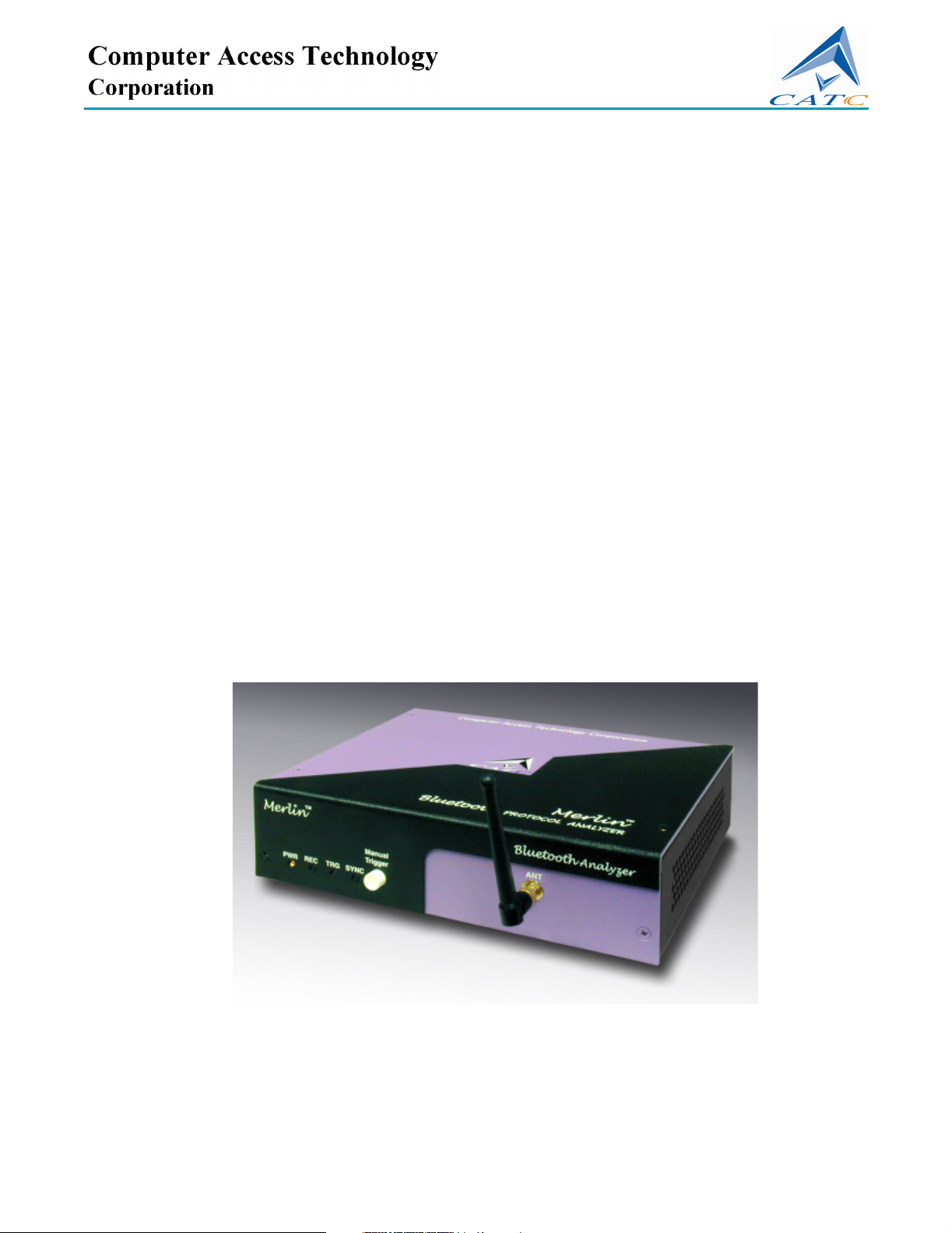
1. Overview
The CATC Merlin™ Protocol Analyzer is a member in CATC's
industry-leading line of high performance, Bluetooth protocol analyzers.
Merlin has been designed using the same modular software and hardware
architecture that made its predecessors highly successful in the serial bus
protocol analyzer market worldwide.
1.1 Bluetooth™ Overview
The Bluetooth™ wireless technology is set to revolutionize the personal
connectivity market by providing freedom from wired connections. It is a
specification for a small-form factor, low-cost radio solution providing links
between mobile computers, mobile phones and other portable handheld
devices, and connectivity to the internet.
The Bluetooth™ Special Interest Group (SIG), comprised of leaders in the
telecommunications, computing, and network industries, is driving
development of the technology and bringing it to market. The Bluetooth™
SIG includes promoter companies 3Com, Ericsson, IBM, Intel, Lucent,
Microsoft, Motorola, Nokia and Toshiba, and more than 2500 SIG
members.
Bluetooth™ is a radio technology specification designed to transmit both
voice and data wirelessly, providing an easier way for a variety of mobile
computing, communications and other devices to communicate with one
another without the need for cables. Bluetooth™ could make possible what
is being called the personal-area network by allowing users to transmit small
amounts of data at 1M bit/sec with a range of 10 to 100 meters, depending
the power of the radio, over the 2.4-GHz radio frequency. The key benefits
of the Bluetooth™ technology are robustness, low complexity, low power
and low cost. Bluetooth™ employs a rapid frequency hopping mechanism
to minimize the effects of ‘collisions’ with other protocols and devices
operating in the same frequency band. Mechanisms exist for a Bluetooth™
device to determine all devices in range as well as to request connection to
a piconet as either a master or a slave.
Please refer to the Bluetooth™ Specification, version 1.1 for details on the
protocol. The Bluetooth™ specification is available from the Bluetooth™
SIG at its web site http://www.bluetooth.org/
1
Page 10

Merlin Protocol Analyzer User’s ManualCATC SW Version 2.0
1.2 General Description
The Merlin Protocol Analyzer is designed as a stand-alone unit that can be
easily configured and controlled by a portable or desktop PC connected via
its USB port. Merlin provides customers with the familiar ‘CATC Trace’
user interface that is the de facto industry standard for documenting the
performance of high-speed serial protocols.
Merlin supports the functionality required to analyze all levels, including
the baseband, of the Bluetooth™ wireless protocol. The featured Radio
Interface allows users to probe and analyze transactions at the lowest level
within the Bluetooth™ architecture. By creating this "Point of Observation"
or probing point within the radio level packet view, the user can analyze all
levels of the protocol stack.
Merlin is a non-intrusive testing tool for Bluetooth™ piconets providing
network traffic capture and analysis. Hardware triggering allows real-time
events to be captured from a piconet. Hardware filtering allows the filtering
out of fields, packets, and errors from the recording. Filtering allows users
to focus recordings on events of interest and to preserve recording memory
so that the recording time can be extended.
Recorded data is presented in colored graphics in a trace viewer application.
This application has advanced search and viewing capabilities that allow the
user to quickly locate specific data, errors and other conditions, thereby
focussing the user’s attention on events of interest.
The Merlin Protocol Analyzer functions with any personal computer using
the Windows 98SE, Windows 2000, Windows NT 4.0, Windows Me, or
Windows XP operating systems and equipped with a functional USB
interface. For an updated set of system requirements for the host machine,
please refer to the readme file.
The Analyzer is configured and controlled through a personal computer
USB port. It can be used with portable computers for field service and
maintenance as well as with desktop units in a development environment.
The Analyzer is easily installed by connecting a cable between the
computer’s USB port and the Analyzer’s USB port.
2
Page 11
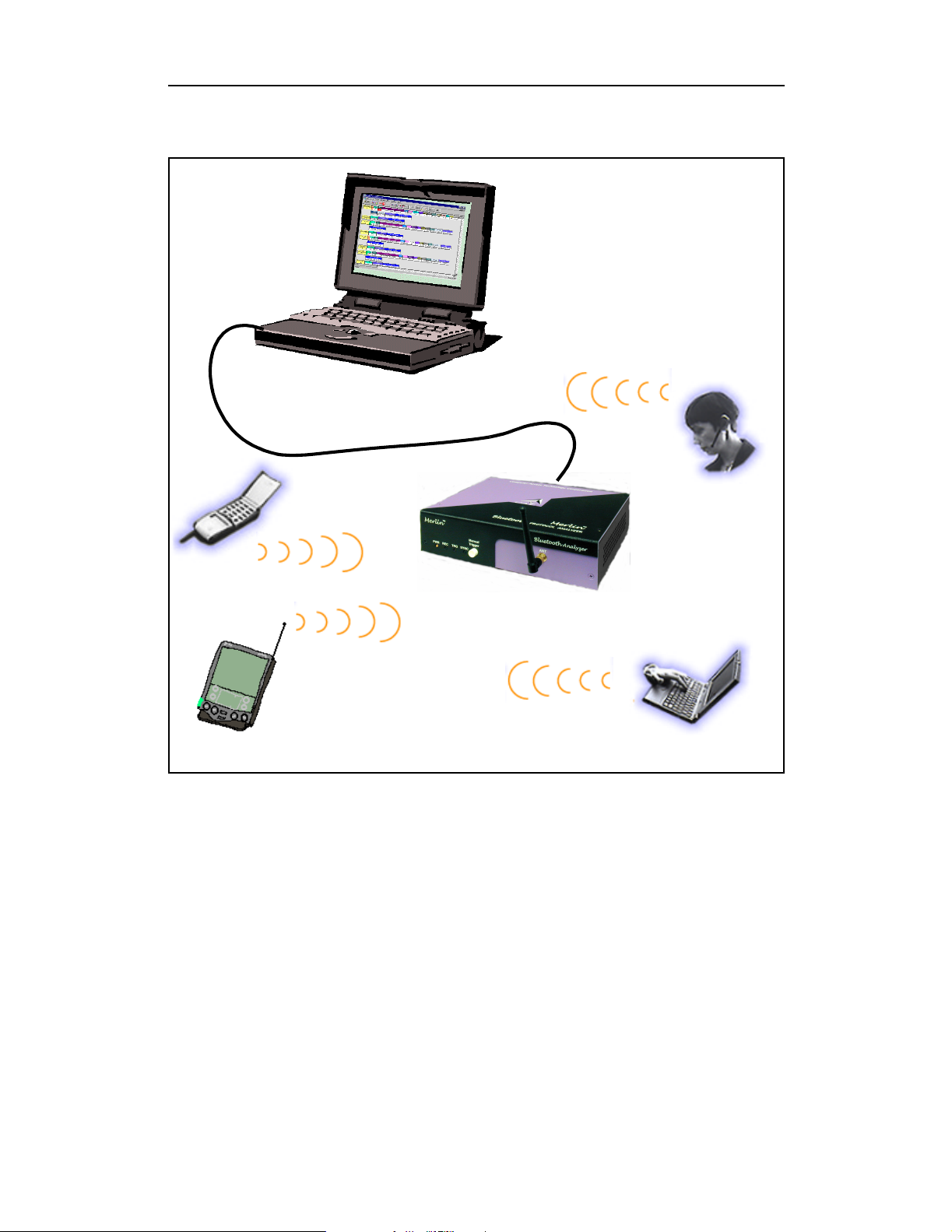
Merlin Protocol Analyzer User’s ManualCATC SW Version 2.0
Sample Bluetooth™ Piconet with Merlin Protocol Analyzer
Merlin provides on-the-fly detection of and triggering on such events as
Packet Headers and Errors. Whether recording manually or with a specified
trigger condition, Merlin continuously records the bus data in a wrap-around
fashion until manually stopped or until the Trigger Event is detected and a
specified post-Trigger amount of bus data is recorded.
Upon detection of a triggering event, the analyzer continues to record data
up to a point specified by the user. Real-time detection of events can be
individually enabled or disabled to allow triggering on events as they
happen. This includes predefined exception or error conditions and a
3
Page 12

Merlin Protocol Analyzer User’s ManualCATC SW Version 2.0
user-defined set of trigger events. The unit can also be triggered by an
externally supplied signal. An external DB-9 connector provides a path for
externally supplied data or timing data to be recorded along with bus traffic.
This DB-9 connector also provides a path for Merlin to transmit externally
two control, timing, or recovered signals for purposes of probing and use by
other circuitry.
The Merlin software provides powerful search functions that enable
investigation of particular events and allow the software to identify and
highlight specific events. In addition to immediate analysis, you can print
any part of the data. Use the Save As feature to save the data on disk for later
viewing. The program also provides a variety of timing information and
data analysis reports.
1.3 Automation
The Merlin software includes an Application Program Interface (API) for
developing testing programs and scripts in C++ and Visual Basic. The API
reproduces most of the commands embodied in the Merlin trace viewer
software. This API allows users to automate procedures that otherwise have
to be run manually via the trace viewer software. The Automation API can
be run locally on the PC attached to Merlin or remotely over a network
connection.
For further details, refer to the Automation API for CATC Bluetooth
Analyzers reference manual included in the installation CD-ROM. You can
also download the document from the CATC website.
1.4 HCI Trace
In addition to the ability to record Bluetooth traffic off-the-air, using the
analyzer's hardware and radio module, the Merlin can record serial
Bluetooth HCI traffic from Bluetooth devices, or 'IUT's (Implementations
Under Test).
While the off-the-air traffic is captured by the analyzers hardware, the HCI
Traffic from the IUTs is captured by the analyzer application using an HCI
probe (provided by CATC) that is connected directly to the IUT hardware.
In a typical setup, the HCI commands and data to transmit are passed from
the Bluetooth application to the Bluetooth baseband (Host to Controller),
while events and data that was received are passed from the Bluetooth
baseband to the Bluetooth application (Controller to Host).
4
Page 13

Merlin Protocol Analyzer User’s ManualCATC SW Version 2.0
To capture the data, the HCI Probe should be connected to the respective
'Host to Controller' and 'Controller to Host' lines. When the recording of the
IUT's HCI is enabled and the application starts a recording, the serial data is
captured as incoming serial data. For this, up to two COM ports should be
configured for each IUT.
1.5 Features
General
• Flexible design - reconfigurable hardware for future enhancements.
• User friendly - the Graphical User Interface software of Merlin Analyzer
is designed to be consistent with the ‘CATC Trace’ using color and
graphics to display Bluetooth™ traffic.
• Radio Level Point of Observation and Capture - traffic capture at the
Radio Level for comprehensive analysis.
• Complies with Bluetooth™ v1.1 specification.
• Supports point-to-point and point-to-multipoint Bluetooth™ piconets.
• Supports 79 frequency hop, reduced and fixed frequency.
• Automatic tracking of changes in the hopping scheme.
• Automatic tracking of whitened and non-whitened packets and traffic.
• Supports recording of serial HCI traffic from implementation under test
(IUT)
• Free non-recording, view-only software available.
• Power-on self-diagnostics.
• Internal 100V to 240 V AC power supply.
• Compliant with FCC class A requirements / meets all CE mark
requirements.
• One year warranty and hot-line customer support.
Physical Components
Note For an updated description of requirements for the host machine, please refer to
the readme file.
• Trace viewer software support for Microsoft Windows versions 98SE
and above.
• Recording memory of 128MB - enough to record 25 minutes of high
volume traffic.
5
Page 14

Merlin Protocol Analyzer User’s ManualCATC SW Version 2.0
Display Options
• Analyzes and displays a transaction-level view of piconet traffic with
accurate time-stamps and frequency hop information.
• Software analysis and data presentation at several protocol levels:
Baseband, LMP, HCI, L2CAP, SDP, RFCOMM, TCS, OBEX, HDLC,
BNEP, PPP, AT, HCRP, IP, TCP, UDP, HID, AVCTP, and AVDTP.
Recording Options
• Flexible advanced triggering capabilities including - multiple triggering
modes, selective views, timing analysis, search functions, protocol
packet errors, transaction errors, packet type and destination device, data
patterns, or any of these trigger types in combination.
• User defined trigger position.
• Support for various piconet characteristics by enabling the user to
configure the synchronization method and recording parameters.
• Real-time hardware filtering of captured traffic for optimizing analyzer
memory usage.
Traffic Generation
Traffic generation capability is provided by Merlin’s Wand.
Bluetooth™ BusEngine
CATC’s BusEngine™ Technology is at the heart of the new Merlin
Analyzer. The revolutionary BusEngine core uses state-of-the-art EPLD
technology and incorporates both the real-time recording engine and the
configureable building blocks that implement data/state/error detection,
triggering, capture filtering, external signal monitoring and event counting
& sequencing. And like the flash-memory-based firmware that controls its
operation, all BusEngine logic is fully field upgradeable, using
configuration files that can be downloaded from the CATC Website.
6
Page 15

Merlin Protocol Analyzer User’s ManualCATC SW Version 2.0
1.6 Specifications
Package
Dimensions: 9.2 x 8.4 x 2.5 inches
(23.4 x 21.3 x 6.4 cm)
Connectors: AC power connection
external clock input (EXT CLK, BNC)
host connection (USB, type ‘B’)
data connector (Data In/Out, 9-pin DB)
Weight: 2.8 lbs. (1.2 kg)
Power Requirements
90-264VAC, 47-63Hz (universal input), 100W maximum
Environmental Conditions
Operating Range: 0 to 55 °C (32 to 131 °F)
Storage Range: -20 to 80 °C (-4 to 176 °F)
Humidity: 10 to 90%, non-condensing
Switches
Power: on/off
Manual Trigger: when pressed forces a trigger event
LEDs
Power (PWR): illuminated when the analyzer is powered on.
Recording (REC): illuminated when the analyzer is actively recording traffic
data.
Triggered (TRG): illuminated during power-on testing, and when the analyzer
has detected a valid trigger condition.
Synchronized
(SYNC):
Recording Memory Size
128M x 8-bit DRAM for traffic data capture, timing, state and other data.
Certification
FCC (Class A), CE Mark
flashes during acquisition of the traffic hop sequence, illuminated when the analyzer is locked to the hop sequence.
7
Page 16

Merlin Protocol Analyzer User’s ManualCATC SW Version 2.0
8
Page 17

Merlin Protocol Analyzer User’s ManualCATC SW Version 2.0
2. Installation
The Merlin Protocol Analyzer components and software are easily installed
and quickly ready to run on most Windows-based personal computer
systems. You can begin making Bluetooth recordings after following these
initial steps.
2.1 System Components/Packing List
• One stand-alone Merlin Analyzer
• One Antenna
• One External Interface Breakout Board with a 9-pin ribbon cable
• One USB cable
• One RF wired Piconet cable
• One SMA Adapter cable (for changing the polarity from reversed to
standard. This cable is used for creating wired piconets.)
• Merlin software program installation CD
• Product documentation
2.2 Analyzer LED and Control Descriptions
The Merlin Analyzer has several user-accessible controls and LEDs.
Figure 1: Front Panel
•RedPWR (power) indicator LED (lights when the unit power is
switched on).
•GreenREC (recording) LED (lights when the unit is recording).
• Yellow TRG (triggered) LED (lights when the unit triggers an event).
Note TRG also lights during power-on testing and will be turned off at the end of the
power on cycle. If the LED blinks at the end of this cycle, the hardware is faulty.
9
Page 18
Merlin Protocol Analyzer User’s ManualCATC SW Version 2.0
•GreenSYNC (synchronized) LED (lights when the unit is locked onto a
specific piconet, based on the Master Address).
• Manual Trigger push-button (allows a manual Trace capture)
— After beginning a recording session, press the Manual Trigger switch to
force a Trigger condition. The session completes when a specified
post-Trigger amount of bus data is recorded or when you manually stop a
recording session.
• ANT Bluetooth™ Antenna connector
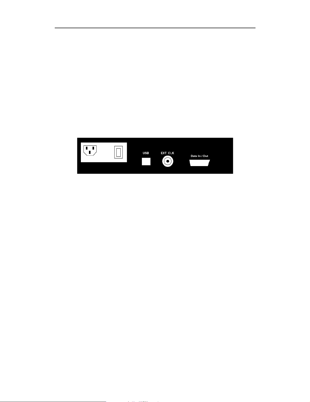
2.3 Merlin Rear Panel Description
Figure 2: Rear Panel
From left to right, the rear panel has the following connectors and switches:
Wide Range AC Connector Module
The power module is composed of:
— Power on/off switch
— Power socket
— Enclosed 5x20 mm 2.0A 250 V fast acting glass fuse
Warning For continued protection against fire, replace fuse only with the type
and rating specified above.
USB type "B" host computer connector
This is the connector that is used to link the analyzer to the PC that will be
administering it.
BNC Connectors "Ext. In" and "Ext. Out"
These connectors allow BNC cables to be attached to the analyzer for the
purpose of triggering on external input signals.
RS-232 25 pin "Data Output" Connector
This connector attaches to a 25 pin RS-232 cable that in turn attaches to an
External Breakout board. The breakout board allows signals to be sent from
the analyzer to an external device such as an oscilloscope.
10
Page 19

Merlin Protocol Analyzer User’s ManualCATC SW Version 2.0
2.4 Setting Up the Analyzer
Step 1 Attach the Antenna to the ANT connection point. The antenna
should point up.
Step 2 Connect the provided AC power cord to the rear of the analyzer and
to a 100-volt to 240-volt, 50 Hz to 60 Hz, 100 W power outlet.
Note The analyzer is capable of supporting supply voltages between 100-volt and
240-volt, 50 Hz or 60 Hz, thus supporting all known supply voltages around the
world.
Step 3 Turn on the power switch on the rear of the analyzer.
Note At power-on, the analyzer initializes itself in approximately ten seconds and
performs an exhaustive self-diagnostic that lasts about five seconds. The Trigger
LED illuminates during the power-on testing and turns off when testing is
finished. If the diagnostics fail, the trigger LED blinks continuously, indicating a
hardware failure. If this occurs, call CATC Customer Support for assistance.
Step 4 Insert the Merlin CD into the CD ROM drive of the PC that will be
administering the analyzer.
Step 5 Connect the USB cable between the USB port on the back of the
analyzer and a USB port on the analyzing PC.
The host operating system detects the analyzer and begins to install the USB
driver.
Step 6 Follow Windows on-screen Plug-and-Play instructions for the
automatic installation of the Merlin Analyzer as a USB device on
your analyzing PC (the required USB files are included on the
Merlin CD.
2.5 Installing the Analyzer Software on the PC
Once Merlin has been recognized as a USB device, install the Merlin
software on the PC administering the analyzer.
Step 1 On the PC, run setup.exe on the installation CD and follow the
on-screen installation instructions.
The Merlin application will install on the PC hard disk.
Step 2 To start the application, launch the CATC Merlin program from the
Start Menu: Start>Programs>CATC>Merlin.
11
Page 20
Merlin Protocol Analyzer User’s ManualCATC SW Version 2.0
The Merlin program opens.
The window shows a menu bar and toolbar at the top, a grey trace viewing
area covering most of the window, and a status bar at the bottom.
Opening a sample trace will cause most of the buttons on the toolbar to
become active.
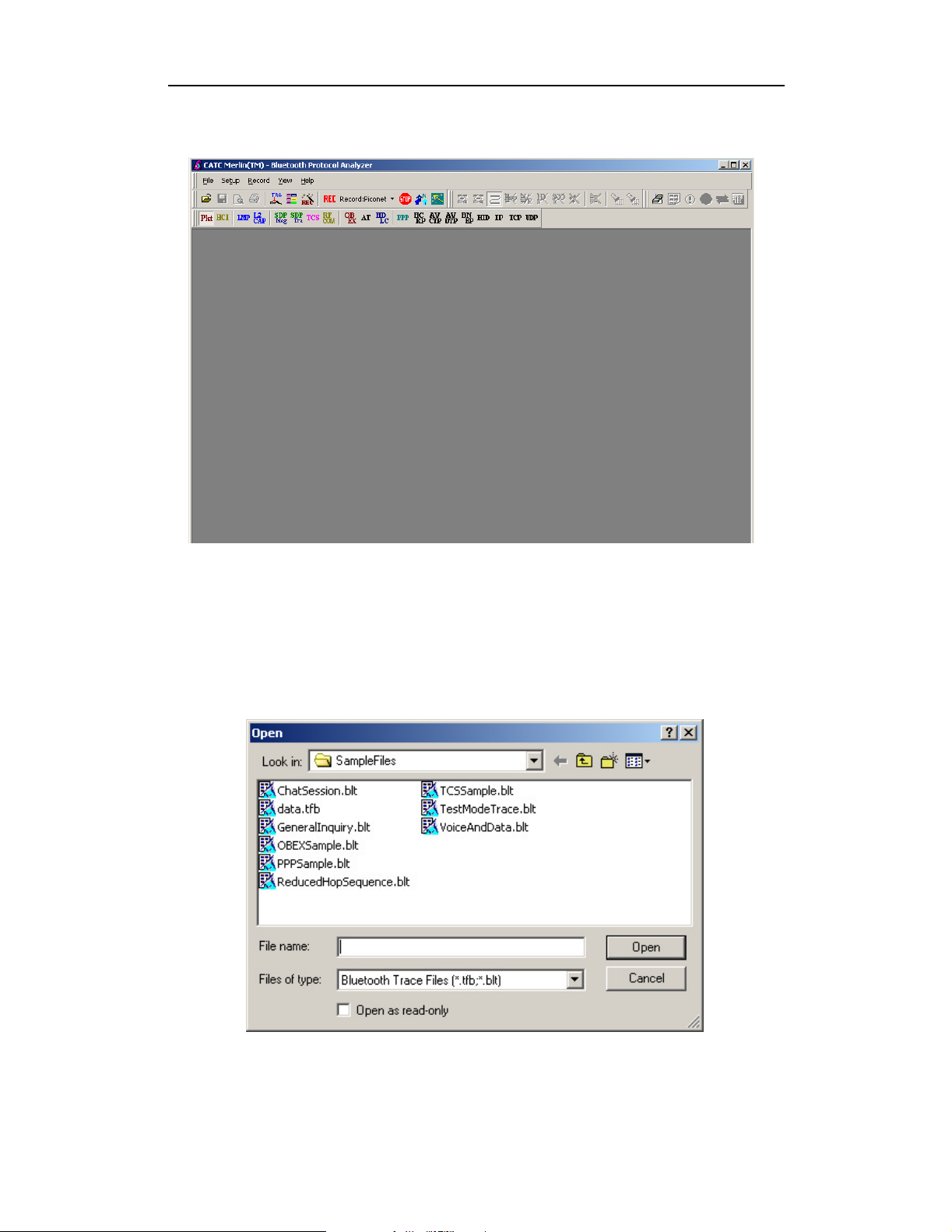
To open a trace,
Step 1 Select File > Open from the menu. A dialog box opens.
Step 2 Select a file from the dialog box and click Open. Atrace
opens in the main viewing area. When traffic has been
12
Page 21
Merlin Protocol Analyzer User’s ManualCATC SW Version 2.0
recorded, it will display here.
Note The software may be used with or without the analyzer box. When used without
an analyzer box attached to the computer, the program functions as a Trace
Viewer to view, analyze, and print captured protocol traffic.
13
Page 22
Merlin Protocol Analyzer User’s ManualCATC SW Version 2.0
2.6 Installing the Probe
If you are planning to record HCI traffic from an Implementation Under
Test (IUT), you will need to connect the provided HCI probe to the IUT.
The HCI Probe is used for connecting the analyzer application running on
the host machine to a single IUT. If more IUTs are to be monitored (up to
three) additional HCI Probes should be used.
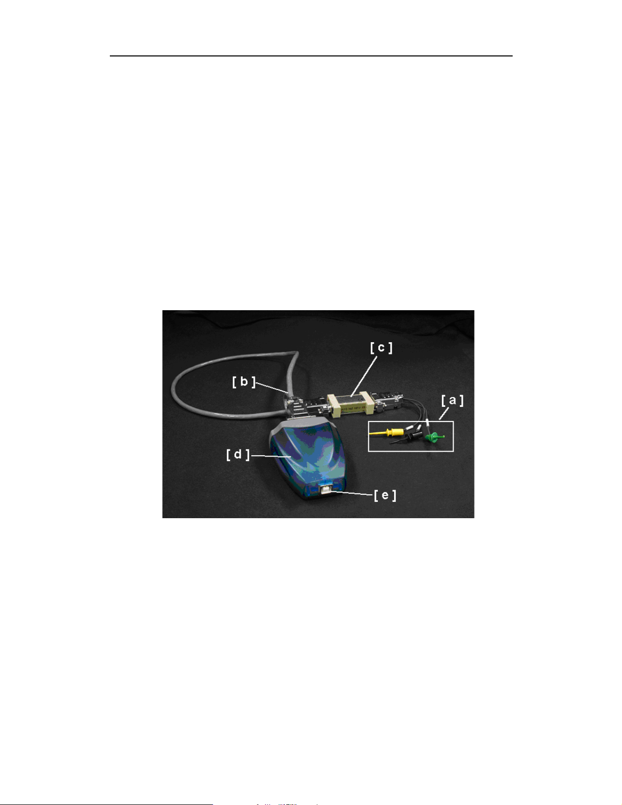
The probe is composed of the following components:
[a] HCITrace Probe Cable
[b] HCITrace RS232 Cable
[c] TTL to RS232 converter
[d] 2-port RS232 to USB converter
[e] USB cable
HCITrace Probe Cable
The HCITrace Probe Cable has three probes:
• ‘Gnd’ – Should be connected to the reference/ground wire
• ‘Host’ – Should be connected to the wire that carries the down-link traffic from
the host to the controller.
• ‘BTC’– Should be connected to the wire that carries the up-link traffic from
the controller to the host.
HCITrace RS232 Cable
Has three DB-9 connectors:
14
Page 23

Merlin Protocol Analyzer User’s ManualCATC SW Version 2.0
• RS-232/Probe - Should be connected to the HCITrace Probe Cable or to the
TTL to RS232 converter (depending whether the signal voltage in the IUT is
TTL or RS-232).
• COM A - Should be connected to one of the serial inputs of the 2-port RS232
to USB converter.
• COM B - Should be connected to one of the other serial input of the 2-port
RS232 to USB converter.
TTL to RS232 converter
Should be used only when the signal voltage in the IUT is TTL and not
RS-232.
The DB-9 connector marked with ‘TTL’ should be connected to the
HCITrace Probe Cable.
The DB-9 connector marked with ‘RS-232’ should be connected to the
'RS-232'/Probe connector of the HCITrace RS232 Cable.
2-port RS232 to USB converter -
This converter is used so the serial signals can be delivered to the host
machine through a USB input.
USB cable –
Connects the 2-port RS232 to USB converter to the Host machine USB
port.
HCI Probe configurations
The HCI Probe can be used in two configurations:
For monitoring UART level signals
•
• For monitoring RS232 level signals
Monitoring UART Level Signals
For monitoring RS232 level signals, the TTL to RS-232 converter should be
used. To assemble the HCI probe for this configuration, perform the
following steps. Refer to the photo and component list shown previously
for references to components [a] through [e].
Step 1 Connect the DB-9 connector of the HCITrace Probe Cable
[a] to the connector marked with ‘TTL’ in the TTL to
RS-232 converter [c].
Step 2 Connect the DB-9 connector marked with ‘RS-232’ in the
TTL to RS-232 converter [c] to the connector marked with
‘'RS-232/Probe’’ in the HCITrace RS-232 Cable [b].
Step 3 Connect the connector marked with ‘COM A’ in the
15
Page 24
Merlin Protocol Analyzer User’s ManualCATC SW Version 2.0
HCITrace RS-232 Cable [b] to ‘Connector A’ in the 2-port
RS232 to USB converter [d].
Step 4 Connect the connector marked with ‘COM B’ in the
HCITrace RS-232 Cable [b] to ‘Connector B’ in the 2-port
RS232 to USB converter [d].
Step 5 Connect the USB cable to the USB connector of the 2-port
RS232 to USB converter [e].
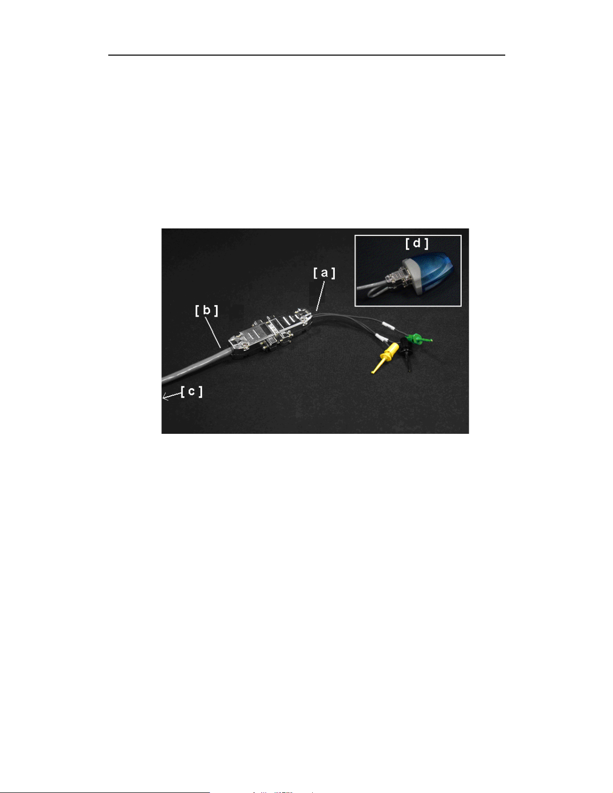
Monitoring RS232 level Signals
Legend for photo:
[a] HCI Probe Cable
[b] HCI Trace RS-232 Cable
[c] Connectors A and B on the other end of the HCI Trace RS-232
Cable
[d] Two-Port RS-232 to USB Converter
For monitoring RS232 level signals do not use the converter. To assemble
the HCI probe for this configuration, perform the following steps:
Step 1 Connect the DB-9 connector of the HCITrace Probe Cable
[a] to the connector marked with ‘'RS-232/Probe’’ in the
HCITrace RS-232 Cable [b].
Step 2 Connect the connector marked with ‘COM A’ in the
HCITrace RS-232 Cable [c] to ‘Connector A’ in the 2-port
16
Page 25
Merlin Protocol Analyzer User’s ManualCATC SW Version 2.0
RS232 to USB converter [d].
Step 3 Connect the connector marked with ‘COM B’ in the
HCITrace RS-232 Cable [c] to ‘Connector B’ in the 2-port
RS232 to USB converter [d].
Step 4 Connect the USB cable [not shown] to the USB connector of
the 2-port RS232 to USB converter [d].
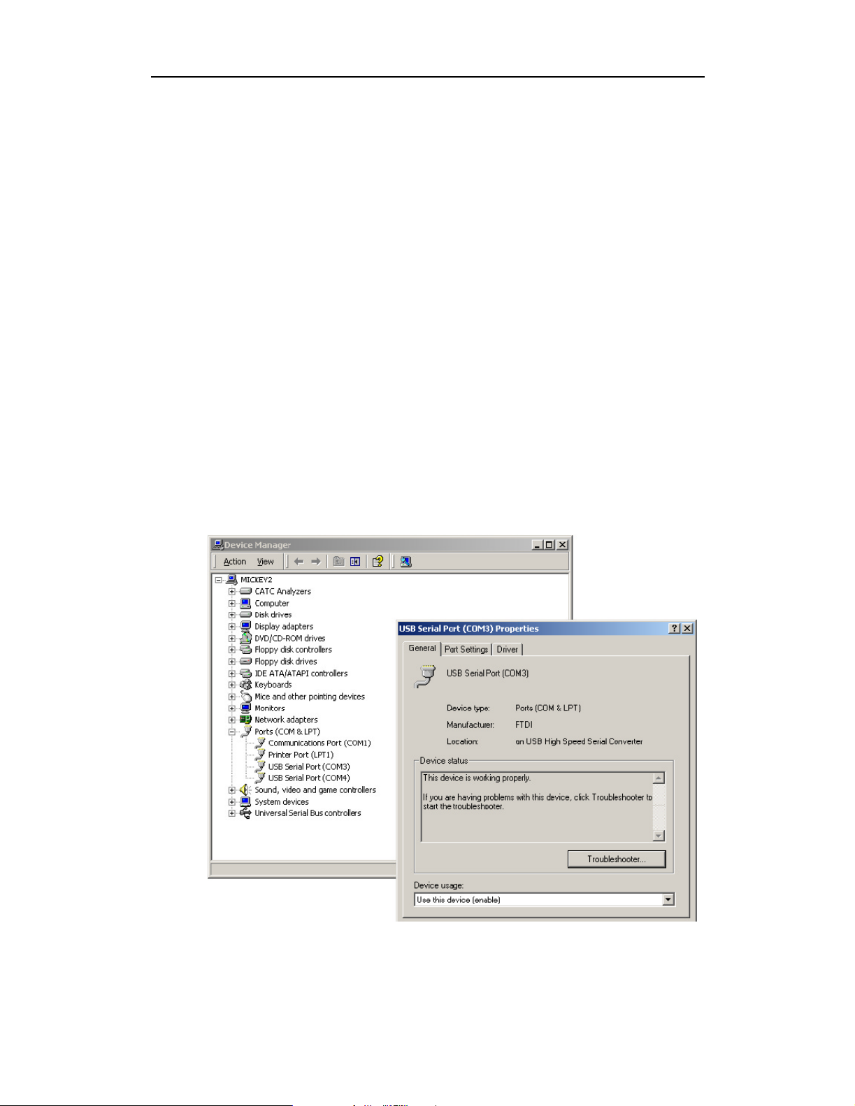
2-port RS232 to USB converter
The 2-port RS232 to USB converter [d] allows the user to connect two serial
connectors to the host machine via a single USB connection. When
connected to the host machine the converter emulates two separate virtual
COM ports that can be used as other real COM ports. Prior of using this
converter as part of the HCI probe several drivers need to be installed. The
drivers are provided on the installation CD-ROM in the HCI Probe\Drivers
sub directory.
Once the converter is connected to a host machine the user is prompted to
provide the place where the system can install the drivers from.
After installing the drivers two new COM ports are going to be available, as
seen in the following snapshot of the Device Manager.
17
Page 26
Merlin Protocol Analyzer User’s ManualCATC SW Version 2.0
2.7 Your First Bluetooth Recording
After installing and launching the software, you can test Merlin by
synchronizing to a piconet and then recording the inquiry traffic. In this
inquiry test, Merlin will issue a General Inquiry that asks local devices to
identify themselves. Merlin then records the responses.
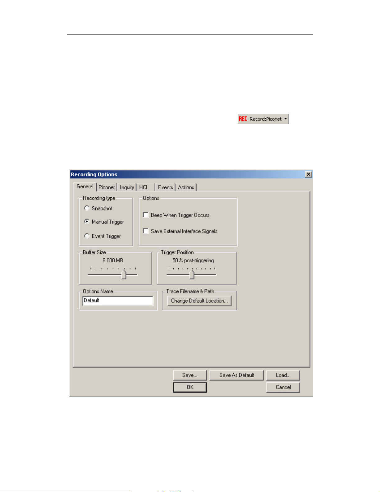
Step 1 Click the down-arrow on the Record
button and select Piconet.
Step 2 From the menu, select Record > Recording Options.
The Recording Options dialog box opens showing factory default settings such as
“manual trigger” and 16 MB buffer size. For the General Inquiry recording you
are about to create, leave these settings unchanged.
18
Page 27

Merlin Protocol Analyzer User’s ManualCATC SW Version 2.0
Step 3 Select the Piconet tab.
The following dialog box will open showing factory default settings. Merlin
defaults to “Page Sync & Record." This setting tells Merlin to
Inquiry and then collect sync information from the specified slave device when the slave
responds. Merlin then waits forthe Master to beginpaging the Slave devices. When paging
begins, Merlin synchronizes to the Master and begins recording.
For this recording, leave most of these settings unchanged. If you are recording a
Hop Frequency that is not 79 Hops Standard, you will need to select the
appropriate standard from the Hop Frequency menu below.
perform a General
Step 4 Click OK to close the Recording Options window and
activate the recording options you selected.
At this point, Merlin will be ready to record.
19
Page 28
Inquiry Recording
Merlin can also record an inquiry process where the Merlin performs a
general inquiry and asks local devices to identify themselves.
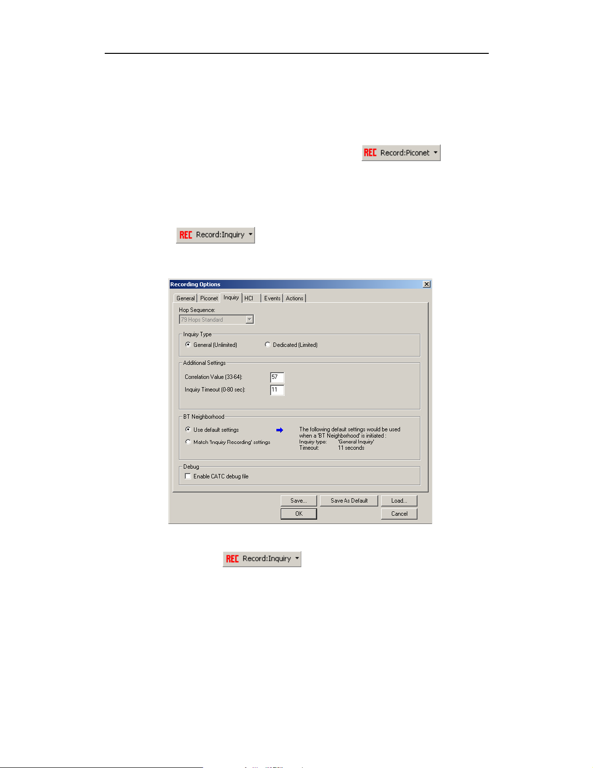
Step 1 Click the down-arrow on the right side of the
Record:Piconet button on the toolbar .
A sub-menu appears with options for Piconet Recording Mode,andInquiry
Recording Mode.
Step 2 Select Inquiry Recording Mode.
The button changes appearance and shows the label Record: Inquiry
Step 3 From the menu, select Setup > Recording Options.
The Recording Options dialog opens with the Inquiry page displaying.
Merlin Protocol Analyzer User’s ManualCATC SW Version 2.0
Step 4 If desired, make any changes to the options, then click OK.
Step 5 Click the button (i.e. the button itself, and
not the down-arrow.)
Merlin starts to record the Bluetooth traffic immediately using the settings from
the Piconet page in the Recording Options dialog. The Bluetooth Inquiry process
will proceed for whatever amount of time is set for creating an Inquiry action (0
to 80 seconds). After the inquiry time has elapsed, the analyzer will uploads the
data and displays the packets.
20
Page 29
Merlin Protocol Analyzer User’s ManualCATC SW Version 2.0
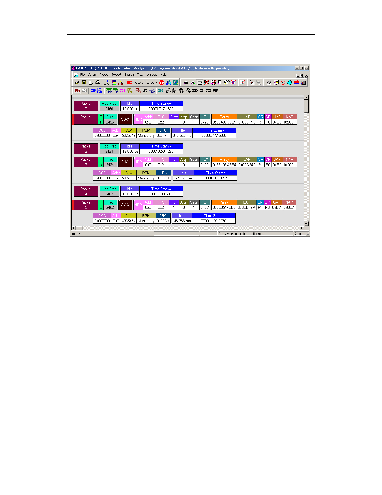
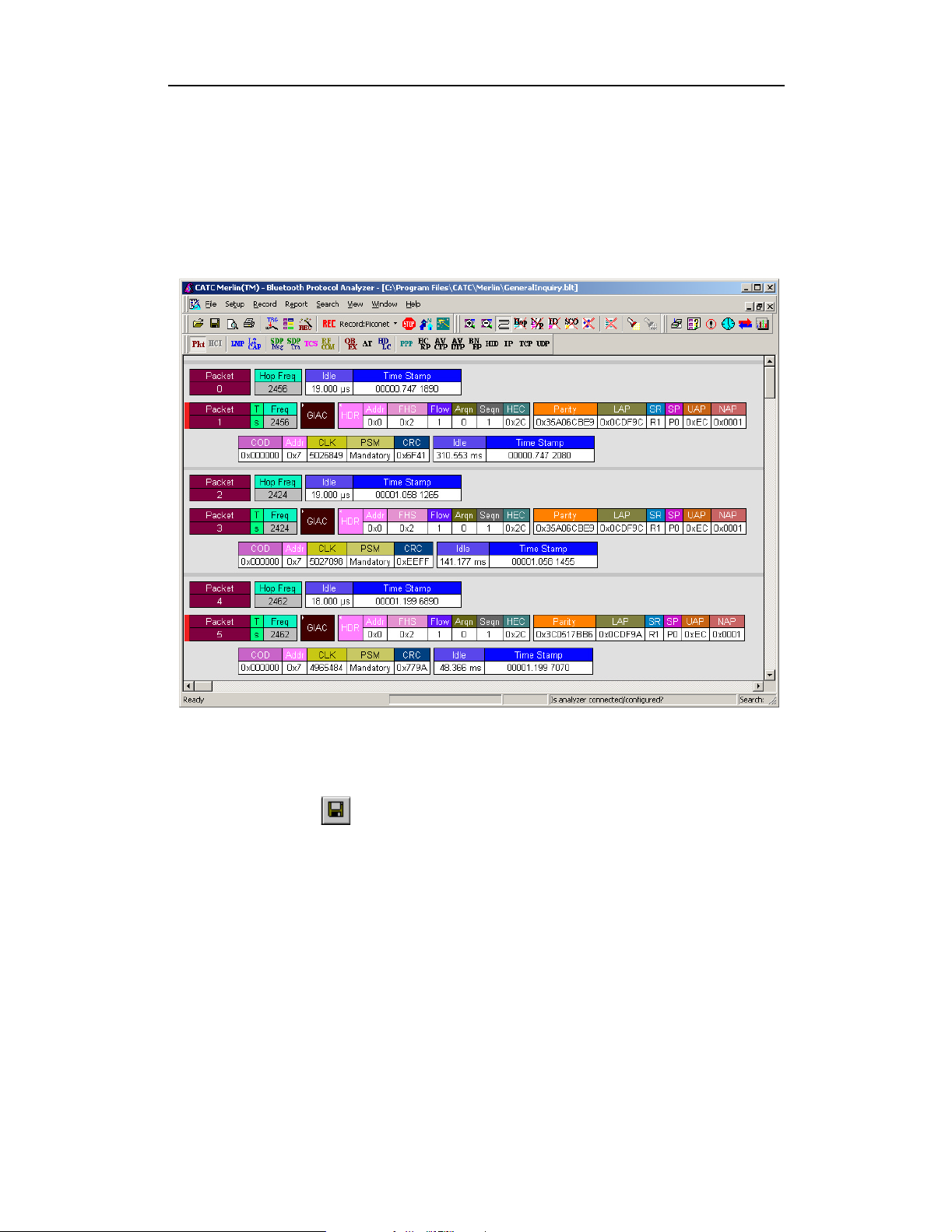
After a few moments, the recording will terminate and the results will display. The
screen should look like the sample recording below which shows the FHS packets
generated during the Inquiry process.
When the recording session is finished, the bus traffic is saved to the hard drive as
a file named data.tfb or whatever name you assign as the default filename. While
the file is being saved, you should see a brown progress bar at the bottom of the
screen. When the bar turns white, it indicates that the data has been saved to disk.
Step 6 To save a current recording for future reference, Select Save As
under File on the Menu Bar.
OR
Click on the Tool Bar.
You see the standard Save As screen.
Step 7 Give the recording a unique name and save it to the
appropriate directory.
2.8 External Interface Breakout Board
The External Interface Breakout Board is an accessory that allows standard,
LV TTL signals to be channeled into the analyzer for triggering or out of the
analyzer for use by an oscilloscope, logic analyzer or other device. Six
ground pins and one 5-volt pin are provided.
21
Page 30
Merlin Protocol Analyzer User’s ManualCATC SW Version 2.0
Drive strength for all outputs is about 30mA high (@2V) and 60 mA low
(@0.5V). Inputs can handle 0 to 5.5V. Inputs above 2V are detected as logic
high; inputs below 0.8V are detected as logic low.
The Breakout Board connects via a cable to the Data In/Out connector
located on the rear of the analyzer unit. Each signaling pin is isolated by a
100Ω series resistor and a buffer inside the Analyzer unit.
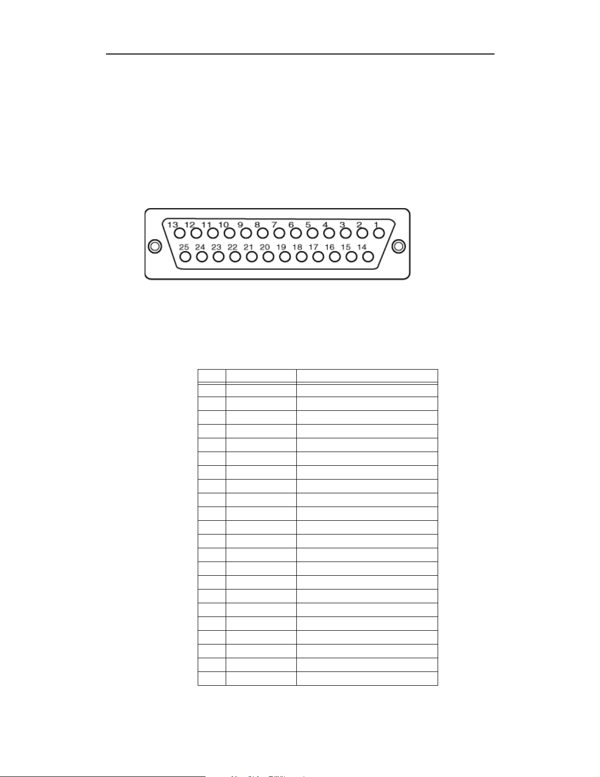
Data In/Out Connector (on cable)
Pin-Outs for the Data In/Out Connector
The following table lists the pin-out and signal descriptions for the Data
In/Out connector on a cable that connects to the Breakout board.
Data In/Out Connector – Pin-Out
Pin Signal Name Signal Description
1RSV Reserved
2 GND Ground
3 GP OUT General Purpose Output
4 TRG IN 1 Trigger In 1
5 GND Ground
6DATA6 Data6
7DATA4 Data4
8DATA3 Data3
9DATA1 Data1
10 GND Ground
11 RSV Reserved
12 RSV Reserved
13 +5V +5 Volts, 250 mA DC Source
14 RSV Reserved
15 GND Ground
16 TRG OUT Trigger Out
17 TRGIN0 TriggerIn0
18 DATA 7 Data 7
19 DATA 5 Data 5
20 GND Ground
21 DATA 2 Data 2
22 DATA 0 Data 0
22
Page 31

Merlin Protocol Analyzer User’s ManualCATC SW Version 2.0
Pin Signal Name Signal Description
23 GND Ground
24 RSV Reserved
25 RSV Reserved
Note (*) Pins 4 and 17 have the same function: they allow external
signals to be used to cause triggering or recording. Pins 3 and 16
are used to transmit output signals. Pins 6, 7, 8, 9, 18, 19, 21, and
22 (data pins) are used to define data patterns for external input
signals. See External Input Signals in Chapter 6.
External Interface Breakout Board
Prototype Rework Area
The Breakout Board contains a prototype rework area for making custom
circuits for rapid development. The area consists of plated-through holes, 20
columns wide by 27 rows long. The top row of holes is connected to GND
and the bottom row is connected to +5V. The remaining holes are not
connected. Use the rework area to insert custom components and wire-wrap
their respective signal, power, and ground pins.
External Recordable Signals
Breakout Board Data 0-1: These pins let you define an 2 bit Data Pattern
that can be recorded in a trace file.
23
Page 32

External Input Triggers
You can use either an external input signal or the Trigger button on the front
of the UPAS to cause triggering. The following descriptions show what
pins or buttons to use:
Breakout Board Data 7 - Data 0: Trigger on an 8-bit input pattern (only
Data1 - Data0 can be recorded into the trace)
Breakout Board Trigger In 0: Selectable Edge triggered inputs. Will
trigger on any edge it detects.
Breakout Board Trigger In 1: Selectable Edge triggered inputs. Will
trigger on any edge it detects.
BNC Trigger (EXT IN): Selectable Edge triggered inputs. Will trigger on
any edge it detects. Located on the back of the chassis.
Push Button Trigger. The Trigger button on the front of the UPAS can be
pressed to manually cause a trigger.
External Outputs
The analyzer can be configured to send an external signal anytime a trigger
and/or event occurs. The following descriptions show the behavior of these
output signals:
Merlin Protocol Analyzer User’s ManualCATC SW Version 2.0
Breakout Board Trigger Out: Changes from low to high when analyzer
triggers (one time per recording only)
Breakout Board G.P. Output: Programmable waveform (low or high
pulse, toggle). Each event can be programmed to enable this external signal.
BNC Output (EXT OUT): Same as Breakout Board G.P. Output. Located
on the back of the chassis.
Configuring the Analyzer for the Breakout Board
To configure the analyzer for the breakout board, see See Section "External
Input Signals" on page 49, See Section "Setting External Output Options"
on page 68, andSee Section "Specifying Pulse Signal Outputs" on page 69.
24
Page 33

Merlin Protocol Analyzer User’s ManualCATC SW Version 2.0
3. Updates
Whenever new software is installed, it is possible that the Firmware and/or
BusEngine will also need updating. Updates can be performed two ways:
either automatically or manually. This chapter describes both procedures.
This chapter also describes how to update Merlin software.
3.1 Software, Firmware, and BusEngine Revisions
The Readme.htm or Readme.txt file on the installation CD and in the
installed directory gives last-minute updates about the current release.
Included with each release are the most recent downloadable images of the
Firmware and the BusEngine. The Readme file lists the latest versions and
informs you if the Firmware or BusEngine needs to be updated.
You can check the current version of the analyzer software, Firmware, and
BusEngine by selecting:
Help > About Merlin… from the menu.
•
You see this screen:
Note The Firmware and BusEngine information will not display if the analyzer is not
connected to its PC or if the analyzer has just booted up and is still in the process
of completing its self diagnostics.
The About Merlin box shown above details revisions of the following
software and hardware:
• Merlin Software Version
• Merlin Firmware Version
• BusEngine Version
• Unit Serial Number
Note When contacting CATC for technical support, please have available all the
revisions reported in the About Merlin window.
25
Page 34

Merlin Bluetooth Analyzer User’s ManualCATC SW Version 2.0
3.2 Software Updates
When a new software release is available, it is posted on the Support page
of the CATC website at www.catc.com/support.html.
To update the software,
Step 1 In the About Merlin screen,verifywhichversionofMerlin
Software you are currently running.
Step 2 Find the latest released software version on the CATC website under
Support.
If you are running the latest version of the software, no further action is needed.
If you are not running the latest version, continue to Step 3.
Step 3 Click on the first link to download the zipped Disk 1 files for your
operating system.
Step 4 Click on the second link to download the zipped Disk 2 files.
Step 5 Unzip the files into your choice of directory.
Step 6 Click Start, then Run, and browse to where you unzipped the files.
Step 7 Select the program named Setup and click Open.
Step 8 Click OK to run the Setup and begin the installation.
Step 9 Follow the on-screen instructions to complete the installation.
Step 10 Read the Readme file for important information on changes in the
release.
3.3 Software License Updates
A license key is a file that CATC provides to you when you enter a
maintenance agreement. You use this file when you make updates to your
CATC software.
Step 1 From the Help menu, select Update License.
26
Page 35

Merlin Protocol Analyzer User’s ManualCATC SW Version 2.0
Step 2 Type the path and filename to the license key or click the Browse
button to map to the directory containing the license key.
Step 3 Click Update Device.
Viewing licensing information
You can also view licensing information to see what version of the license
you are running.
From the Help menu, select Display License Information.
The following window appears containing information about the current
status of your analyzer’s license:
3.4 Automatic BusEngine and Firmware Updates
When Merlin’s software is updated, the software may become incompatible
with the BusEngine and Firmware. When you attempt to record, an error
message will appear asking you to update the BusEngine and Firmware.
The following steps describe the update process.
Step 1 If needed, update the Merlin software using the steps outlined in
"Software Updates" described above.
Step 2 Turn on the Analyzer.
Step 3 On the toolbar, click the button.
Step 4 Since the BusEngine and/or the Firmware are incompatible with the current
Merlin software version, an error message will appear displaying your current
27
Page 36

Merlin Bluetooth Analyzer User’s ManualCATC SW Version 2.0
versions and indicating what versions you need to install.
Step 5 Click Ye s .
The above window closes and the Analyzer Setup window opens.
Step 6 Click Update BusEngine or Update Firmware on the Analyzer
Setup screen.
You can select only one item at this point. If both the BusEngine and the
Firmware need to be updated, the update will complete for the first item and then
return to the above screen so the second update can be performed.
When the second update has finished, you will see the following message telling
you that the update is complete.
Step 7 Power cycle Merlin to complete the update.
28
Page 37

Merlin Protocol Analyzer User’s ManualCATC SW Version 2.0
3.5 Manual BusEngine Updates
You can manually update Merlin’s BusEngine by performing the following
steps:
Step 1 Select Setup > Analyzer from the menu.
Yo u s ee t h e Analyzer Setup screen:
Step 2 Click Update BusEngine
The BusEngine core is the heart of the Merlin Analyzer. Using
state-of-the-art PLD technology, it incorporates both the high speed
recording engine and the configurable building blocks that implement
data/state/error detections, triggering, capture filtering, external signal
monitoring, and event counting and sequencing. Both the BusEngine
program and the Firmware that manages the internal microcontroller are
fully field updateable.
Yo u s ee t h e Select engine file window:
The program has already automatically searched for the correct file and displays
it in the File name field.
29
Page 38

Merlin Bluetooth Analyzer User’s ManualCATC SW Version 2.0
Note The most current Primary BusEngine file (Merlin.rbf) was copied to your
\CATC\Merlin directory when you installed the program.
Step 3 Click Open.
It is not necessary to restart the Analyzer. Once updated, the Analyzer takes
approximately 15 seconds to reinitialize, with Time Remaining displayed
on the screen. During this time the Trigger LED is on, indicating that
power-on diagnostics are being run. If there is a hardware failure, the
Trigger LED continues to blink after initialization is complete. If this
occurs, contact CATC for customer support.
3.6 Manual Firmware Updates
To manually update the firmware,
Step 1 Click Update Firmware on the Analyzer Setup screen.
Yo u s ee t h e Select firmware file window:
The program has already automatically searched for the correct file and displays
it in the File name field.
Step 2 Click Open.
The Analyzer updates the Firmware.
Step 3 Unplug the USB cable from the back of the Analyzer box and then
reinsert it so the new Firmware update can take effect.
30
Page 39

BTTra cer Protocol Analyzer User’s ManualCATC SW Version 2.0
4. Software Overview
4.1 The Main Display Windows
While some of the analyzer’s Main Display window options are familiar,
many contain options specific to the analyzer program.
Table 1: Main Display Pull-Down Windows
Menu Function
File
Open… Opens a file
C
lose Closes the current file
Save A
s… Saves all or a specified range of packets from the current file with a
specified name
P
rint… Prints part or all of the current traffic data file
Print Prev
Pr
E
dit Comment… Creates or edits the Trace file comment field
Export
Text (Packet View
Format)
Export
CSV Text
Export
Streams
Last File Lists the last files that were opened
Ex
iew Produces an on-screen preview before printing
int Setup… Sets up your current or new printer
»Packets to
»Packets to
>>Audio
it Exits the Merlin program
Saves all or part of a trace to a text file
Saves all or part of a trace to a Comma Separated Values (CSV) file
suitable for viewing in a spreadsheet application
Saves audio data into a file. Presents options for setting the Audio
Source format, Output File format, Stream Direction, and Output
Sampling
Setup
Display Options Provides the control of various display options such as color, formats,
and filters.
ecording Options Opens a dialog box with checkboxes and drop-down menus for setting
R
up a recording.
Recording W
A
nalyzer Allows the operator to reset the Analyzer or update the BusEngine and
izard Starts a sequence of interactive dialog boxes that configures Merlin for
a recording. This utility provides an alternative to the Recording
Options dialog box.
Firmware.
Record
Start Causes the Analyzer to begin recording Bluetooth activity.
Stop
Causes the Analyzer to stop recording.
31
Page 40

BTTra cer Protocol Analyzer User’s ManualCATC SW Version 2.0
Menu Function
Recording Mode Presents a drop-down menu with options for setting the analyzer's
recording mode:
Piconet Recording Mode -- Causes Merlin to monitor and record
piconet traffic. Merlin records the traffic data as specified in the
Recording Options, then uploads the data as a Trace file when the
recording is complete.
Inquiry Recording Mode -- Causes Merlin to perform an inquiry to
detects and records Bluetooth devices within range. After completing
the recording, Merlin uploads the trace to the PC and saves it as a Trace
file.
IUT: HCI Recording Mode -- Causes the Merlin software to record
HCI traffic from the IUT. In this mode, the Merlin software on the host
PC directly records IUT traffic without first going through the analyzer.
T Neighborhood
B
Inquiry
Displays Bluetooth Address and clock frequency for devices in range.
The expected Bluetooth clock frequency is 3200 Hz +/- 250 ppm.
Report
File Information Details such information about the recording as number of packets and
triggering setup.
rror Summary Displays an error summary of the current trace file and allows you to
E
go to a specific packet, and save the error file to a uniquely named file.
Timing C
T
alculation Starts the calculator dialog for calculating various timing and
bandwidth parameters in the recording file.
raffic Summary Details the number and type of packets were transferred during the
recording, as well as message-level statistics.
Search
Go to trigger Positions the display to show the first packet that follows the trigger
event.
Go to
P
acket/Message/
Protocol ...
Go to M
Go to » Enables quick searching for specific events using a cascade of pop-up
Find Allows complex searches.
Find N
Search Direction Allows you to specify a forward or backward search of a trace file.
arker » Positions the display to a previously marked packet.
ext Repeats the previous Find operation. Can also use F3 to find next.
Positions the display to the indicated packet, LMP/L2CAP message, or
Protocol Message (RFCOMM, TCS, or SDP protocols).
windows.
32
Page 41

BTTra cer Protocol Analyzer User’s ManualCATC SW Version 2.0
Menu Function
View
Toolbars Presents a sub-menu with options for displaying/hiding the toolbars
and an option called Customize which allows the menus and toolbars to
be customized or reset to factory default.
tatus Bar Switches display of the Status Bar on or off.
S
Unhide Cells > Presents a menu of currently hidden cells. Allows you to unhides any
cells that were hidden through the Display Options dialog box (View >
Display Options > Color/Format/Hiding)
Zoom In
Zoom Out
rap Allows the display to wrap.
W
Device List
Real-time
Statistics
Decoding
Assignments
L2CAP Connections Lists current L2CAP connections.
Increases the size of the displayed elements.
Decreases the size of the displayed elements.
Displays a list of discovered Bluetooth devices and allows you to add
and delete devices and security settings by selecting the device,
pressing the security button, and modifying the settings.
Opens a dialog box with a graphical summary of the traffic currently
being recorded by the Analyzer. Real-time monitoring allows
continuous monitoring and displaying of traffic and related statistical
dada in a piconet. This processed data is displayed in a set of
configurable graphs.
Lists current L2CAP decoding assignments.
RFCOMM Channel
Assignments
L
evels Presents a menu of display levels. This menu replicates the
Lists current RFCOMM assignments.
Decode/Display buttons in the toolbar such as Packets, L2CAP, TCS
etc.)
Window
New Window Switches display of the Tool Bar on or off.
ascade Displays all open windows in an overlapping arrangement.
C
ile Arranges multiple trace windows as a series of strips across the main
T
display area or as a series of side-by-side tiles.
Arrange Icons Arranges minimized windows at the bottom of the display.
W
indows Displays a list of open windows.
33
Page 42

BTTra cer Protocol Analyzer User’s ManualCATC SW Version 2.0
Help
Online Help Displays Help topic associated with current Merlin window.
H
elp Topics... Displays online help.
U
pdate License... Opens a dialog box for entering license key information for the
analyzer.
D
isplay License
Information...
A
bout Merlin... Displays version information about Merlin.
Displays current license information for the analyzer.
4.2 Toolbar
The Tool Bar provides access to the most popular program functions. Tool tips
describe icon functionality as the mouse arrow is moved over the icon/item.
Open file View/Hide L2CAP Message Level
Save As View/Hide SDP Message Protocol Level
Preview View/Hide SDP Transaction Protocol Level
Print… View/Hide TCS Protocol Level
SetupRecordOptions
Start
Recording - presents options
for recording piconet,
inquiry, or IUT:HCI traffic
Stop Recording View AT Commands Protocol Level
Start Recording Wizard View/Hide HDLC Protocol
Bluetooth Neighborhood.
Performs an inquiry and then
lists the local devices that it
discovered
View/Hide RFCOMM Protocol Level
View/Hide OBEX Protocol Level
View/ Hi de P PP
Start Merlin’s Wand View/Hide HCRP
34
Page 43

BTTra cer Protocol Analyzer User’s ManualCATC SW Version 2.0
Setup Display Options View/Hide AVCTP
Zoom In View/Hide AVDTP
Zoom Out View/Hide BNEP Protocol
Wrap View HID Protocol Layer
Hide Frequency Hops View IP Protocol Layer
Hide Nulls & Polls
Hide ID Packets View UDP Protocol Layer
Hide Voice (SCO) Packets Display device list
Hide devices that were
specified in the Display
Options dialog box
Hide Unassociated Traffic Error Summary
Complex Find Timing Calculations
Find Next Traffic Summary
View Packet Level
(Baseband)
View/Hide LMP Message
Level
View TCP Protocol Layer
File Information Report
Display Bus Utilization graph
Display Real-Time Statistics
4.3 Status Bar
The Status Bar is located at the bottom of the main display window.
Depending on the current activity, the bar can be divided into as many as
four segments. The figure below demonstrates the various displays in the
status bar.
View HCI Protocol layer.
35
Page 44

Recording Progress
When you begin recording, the left-most segment of the Status Bar displays
a Recording Progress Indicator. The following figure displays the various
indications of the status bar:
BTTra cer Protocol Analyzer User’s ManualCATC SW Version 2.0
Status Bar Position Definitions:
The following numbered definitions correspond to the number labels on the
above status bars.
1 Analyzer is not connected or not configured.
2 Idle mode: Analyzer is connected to the host machine, but is not doing any
attempts to synchronize to a piconet nor record Bluetooth traffic.
3 Analyzer is trying to synchronize to the piconet with the master device that has
BD_Address 00837163787.
4 Analyzer is synchronized to the piconet with the master device that has
BD_Address 00837163787.
5 Analyzer is recording the traffic of the piconet with the master device that has
BD_Address 00837163787. However, no triggering occurred.
6 A trigger event occurred, and the analyzer is recording the traffic of the piconet
with the master device that has BD_Address 00837163787. However, no
triggering occurred.
7 Analyzer is performing a BT Neighborhood action, where it makes inquiries
for Bluetooth devices.
8 Merlin application uploads recorded data from the analyzer at the end of a
recording session.
As recording progresses, the Progress Indicator changes to reflect the
recording progress graphically:
36
Page 45

BTTra cer Protocol Analyzer User’s ManualCATC SW Version 2.0
• In the Progress Indicator, a black vertical line illustrates the location of the
Trigger Position you selected in Recording Options.
— Pre-Trigger progress is displayed in the field to the left of the Trigger
Position in the before-Trigger color specified in the Display Options.
— When the Trigger Position is reached, the progress indicator wiggles as it
waits for the trigger.
— After the trigger occurs, the field to the right of the Trigger Position fills
in the post-Trigger color specified in the Display Options.
— When recording is complete, the upper half of the progress indicator fills
in white, indicating the progress of the data upload to the host computer.
You should be aware of two exceptional conditions:
If a Trigger Event occurs during the before-Trigger recording, the
•
before-Trigger color changes to the after-Trigger color to indicate that not all
the expected data was recorded pre-Trigger.
• When you click Stop before or after a Trigger Event, the Progress Bar adjusts
accordingly to begin uploading the most recently recorded data.
The Progress Bar fills with color in proportion to the specified size and
actual rate at which the hardware is writing and reading the recording
memory. However, the Progress Indicator is normalized to fill the space
within the Status Bar.
Recording Status
During recording activity, the current Recording Status is temporarily
displayed in the next segment. When you activate the Record function, this
segment flashes one of the following messages (depending on the selected
Recording Options):
After recording stops,
To abort the upload process,
— Trigger?
— Triggered!
— Uploading
— The flashing message changes to Uploading data–x%done(x%
indicates the percentage completion of the data uploading process).
— The traffic data is copied to disk (overwriting any previous version of this
file) using the default file name data.tfb or a new name specified in the
Recording options.
Click in the Tool Bar.
You are prompted to choose whether to keep the partially uploaded data or to
throw it away.
37
Page 46

When the data is saved, the Recorded Data file appears in the main display
window and the Recording Status window is cleared.
• If the recording resulted from a Trigger Event, the first packet following the
• If the recording did not result from a Trigger Event, the display begins with the
Analyzer Status
The third segment in the status bar displays analyzer status. The status will
display one of the following:
No Sync - the system is not synced to any piconet
Inquiring... - The system is performing an Bluetooth Inquiry
Syncingto[XXX]...-- The system is attempting to synchronize to a piconet
where the device with BD_Address XXX is the master.
Synced to [XXX] - The system is synchronized to a piconet where the
device with BD_Address XXX is the master.
BTTra cer Protocol Analyzer User’s ManualCATC SW Version 2.0
Trigger (or the packet that caused the Trigger) is initially positioned second
from the top of the display.
first packet in the traffic file.
Recording [XXX] - system is recording the Bluetooth traffic of the piconet
where the device with BD_Address XXX is the master.
After the analyzer has synchronized to the Bluetooth piconet under
observation, the Status Bar will display activity bars and the strength (in
dBm) of the radio signal that Merlin is receiving. The activity bars will
increase or decrease with activity. The signal strength readings will display
as five possible values:
•below-60dBm
• - 60 dBm
• - 50 dBm
• - 40 dBm
• above - 40 dBm
The valid range for a signal is between -60 and - 40 dBm
Search Status
The rightmost segment displays the current search direction: Fwd (forward)
or Bwd (backward).
Zoom In
Zoom In increases the size of the displayed elements, allowing fewer (but
larger) packet fields per screen.
38
Page 47

BTTra cer Protocol Analyzer User’s ManualCATC SW Version 2.0
• Click on the Tool Bar.
Zoom Out
Zoom Out decreases the size of the displayed elements, allowing more (but
smaller) packet fields per screen.
Click on the Tool Bar.
•
4.4 Tool Tips
Throughout the application, tool tips provide useful information.
To display a tool tip, position the mouse pointer over an item. The tool tip
displays in a short moment if present. Tool tips can also be found over the
Tool Bar and in areas of the packet view screen.
4.5 Merlin Analyzer Keyboard Shortcuts
Several frequently-used operations are bound to keyboard shortcuts.
Table 2: Keyboard Shortcuts
Key Combination Operation Key Combination Operation
Ctrl+O Open file Ctrl+P Print...
Ctrl+Home Jump to First packet Ctrl+End Jump to Last packet
Ctrl+F Search Forward Ctrl+B Search Backward
F3 Find Next Ctrl+L Search for Loss of Sync
Shift+I Goto ID packet Shift+R Goto Freq Hop packet
Shift+P Goto Poll packet Shift+N Goto Null packet
Shift+M Goto DM1 packet Shift+F Goto FHS packet
Shift+1 Goto HV1 packet Shift+H Goto DH1 packet
Shift+3 Goto HV3 packet Shift+2 Goto HV2 packet
Shift+A Goto AUX1 packet Shift+V Goto DV packet
Shift+5 Goto DH3 packet Shift+4 Goto DM3 packet
Shift+7 Goto DH3 packet Shift+6 Goto DM5 packet
Shift+S Search for Soft Error Shift+E Search Error
39
Page 48

BTTra cer Protocol Analyzer User’s ManualCATC SW Version 2.0
40
Page 49

BTTra cer Protocol Analyzer User’s ManualCATC SW Version 2.0
5. Recording Wizard
Recording Wizard is an interactive utility that presents a series of
user-friendly dialog boxes for setting up a recording session. Recording
Wizard serves as an alternative method of configuring the Recording
Options dialog box. When you are finished using the Wizard, you can view
your settings in the Recording Options window. By providing data to the
prompts in the Wizard’s dialog boxes, you configure Merlin for a recording
session.
Starting Recording Wizard
To start the Recording Wizard,
• Click on the Tool Bar or select Recording Wizard under Setup on the
Menu Bar.
Yo u s ee t h e Recording Options window:
The Recording Options window has three buttons marked Next, Back,and
Cancel that allow you to move forward or backward through the wizard or
to cancel the wizard.
To begin advancing through the wizard,
• Click Next to see the options for the three types of recordings that the
Recording Wizard can make.
41
Page 50

BTTra cer Protocol Analyzer User’s ManualCATC SW Version 2.0
The Wizard advances to the next screen which presents three options:
• I want to establish a new piconet and have Merlin record traffic on that
piconet.
This option causes Merlin to perform an Inquiry so it can discover local
devices and then establish a new piconet and record the piconet traffic.
• I want Merlin to record traffic on a piconet that has already been
established.
This option lets Merlin record traffic from an already established piconet.
• I am using Bluetooth Test Mode and want Merlin to record traffic on my
test piconet.
This option lets Merlin create either a single frequency range recording
of a range that you specify or create a recording of a limited hop
frequency range consisting of 5 frequency hops.
5.1 Recording a Traffic on a New Piconet
The New Piconet option shown in the previous screen presents users with
the means of recording the traffic from a new piconet. This option will
cause a sequence of screens to prompt you for information such as the
piconet Master address.
42
Page 51

BTTra cer Protocol Analyzer User’s ManualCATC SW Version 2.0
The following steps shows you how to configure Merlin to record a new
piconet.
Step 1 From the screen shown in the previous screenshot, select the
first option: I want to establish a new piconet and have
Merlin record traffic on that piconet,thenpressNext.
The following screen displays.
Step 2 Select Perform Inquiry Now,thenpressNext.
Selecting Perform Inquiry Now will cause Merlin to perform a General
Inquiry and collect addresses and other details about local Bluetooth
devices. If you already have address information for your Bluetooth
devices you can choose Skip Inquiry. Choosing Skip Inquiry will
cause the Recording Wizard to advance to Step 6. If you are not sure
what option to select, choose Perform Inquiry Now.
43
Page 52

BTTra cer Protocol Analyzer User’s ManualCATC SW Version 2.0
The following screen will display.
You will see two options:
• I want to search for all Bluetooth devices within range
This option will cause Merlin to search for all Bluetooth devices that are
in range and ready to transmit and receive data (i.e., in Inquiry Scan
Mode)
• I want to search only for devices corresponding to the following
(hexadecimal) DIAC:
This option will cause Merlin to search for the class of devices that you
specify in the DIAC text box. DIAC stands for Device Inquiry Access
Code. Values are entered in hexadecimal format. You can get DIAC
values from the Bluetooth Specification.
Step 3 Select the first option: I want to search for all Bluetooth devices
44
Page 53

BTTra cer Protocol Analyzer User’s ManualCATC SW Version 2.0
within range,thenpressNext. The following screen will display.
You will see two options:
Step 4 In the text box, enter the length of time you want Merlin to search
for nearby devices.
The default value is 11. If you do not sure what time value to enter, use
the default value.
Step 5 Press Next.
Before the Inquiry, Merlin tests the hardware connection. In the case of
failure, the following screen will display.
Clicking OK will close the message box.
45
Page 54

BTTra cer Protocol Analyzer User’s ManualCATC SW Version 2.0
If Merlin passes the hardware test, it will search for devices. The
Recording Wizard will display a progress bar and a message telling you
that a search is under way:
If no device is found, the Recording Wizard will display the following
screen:
46
Page 55

BTTra cer Protocol Analyzer User’s ManualCATC SW Version 2.0
If devices found, the Recording Wizard will display the following screen:
Step 6 Press Next.
The following window will display:
Step 7 Select from the drop-down menu the hexadecimal address for your
Master device. If you do not see your device’s address, you may
type it into the text box yourself.
47
Page 56

BTTra cer Protocol Analyzer User’s ManualCATC SW Version 2.0
The following window will display:
Step 8 Select from the drop-down menu the hexadecimal address for your
slave device into the box labeled Piconet Slave Address. If you do
not see your slave’s address, you can type it into the box.
Step 9 Press Next.
The following screen will display.
This screen displays the settings you selected.
48
Page 57

BTTra cer Protocol Analyzer User’s ManualCATC SW Version 2.0
The Advanced button on the right will open the Recording Options
dialog box shown below. This screen will show the settings you selected
through the Recording Wizard have been applied to the Recording
Options dialog.
Step 10 Press Next to advance the Recording Wizard to the next screen.
The following screen displays:
Merlin pages the Master and if specified in Step 8, the Slave devices.
49
Page 58

BTTra cer Protocol Analyzer User’s ManualCATC SW Version 2.0
If Merlin is unable to complete its pages, the following screen will
display:
If Merlin is able to complete its pages, it will enter into a synchronizing
state and then wait for you to create the piconet. During this waiting
period, Merlin will display the following screen:
50
Page 59

BTTra cer Protocol Analyzer User’s ManualCATC SW Version 2.0
Once you have created the piconet, Merlin will synchronize to the
piconet and begin recording. During the recording, Merlin will display
the following screen:
At the completion of the recording, Merlin will display the following
screen:
You can repeat the recording by pressing the Repeat button.
Step 11 To close the wizard, press the Close button.
51
Page 60

BTTra cer Protocol Analyzer User’s ManualCATC SW Version 2.0
The wizard will close and your trace will display.
5.2 Recording an Existing Piconet
Using Recording Wizard to record an existing piconet is similar to recording
a new piconet. The main difference is that you will be asked if your Master
device can support multiple slave devices and whether it can respond to
pages once it has created a piconet with another device.
Step 1 To start the Recording Wizard, press or select Setup >
Recording Wizard from the menu.
52
Page 61

BTTra cer Protocol Analyzer User’s ManualCATC SW Version 2.0
The Recording Wizard introductory page will open:
Step 2 Press Next to advance to the next screen.
You will see three choices:
Step 3 Select the second option: I want Merlin to record traffic
on a piconet that has already been established.
Step 4 Press Next.
53
Page 62

BTTra cer Protocol Analyzer User’s ManualCATC SW Version 2.0
You will see two choices:
Step 5 Select Perform Inquiry Now.
You will see two choices:
Step 6 Select the first option: I want Merlin to search for all
Bluetooth devices within range.
54
Page 63

BTTra cer Protocol Analyzer User’s ManualCATC SW Version 2.0
If you want to limit the inquiry to a class of devices, select the second
option and enter the hexadecimal value for the device class in the text
box.
Step 7 Press Next.
The following screen will appear:
Step 8 If you want to change the search duration, type in a new
value into the text box. Otherwise, use the default value (20
seconds), then press Next.
55
Page 64

BTTra cer Protocol Analyzer User’s ManualCATC SW Version 2.0
If Merlin cannot detect other devices, the following message will
display:
If Merlin passes the hardware test, it will then goes onto conduct a
General Inquiry to locate local Bluetooth devices.
56
Page 65

BTTra cer Protocol Analyzer User’s ManualCATC SW Version 2.0
If Merlin finds Bluetooth devices, it will display the following message:
Check the Device List to see if Merlin found all of the devices in your
piconet. If you feel that the list is incomplete, you can close this window
andpressthebuttonmarkedRepeat. This will cause Merlin to repeat the
General Inquiry and recollect information on local Bluetooth devices.
Step 9 Press Next to advance to the next screen.
The following screen will prompt you for the Master device’s address.
The address can be selected from the menu or typed into the box:
57
Page 66

BTTra cer Protocol Analyzer User’s ManualCATC SW Version 2.0
Step 10 Select or type in the Master device’s address into the box
next to the label Piconet Master Address.
Step 11 Press Next.
The following screen will display. This screen asks you which of the
following two options apply to your Master device. For some devices,
both options will apply.
You can select either or both options. They are not mutually exclusive:
If the Master supports inquiries while in a connected state, select the first
option. This will set Merlin to use the 'Sync & Record' mode in its
attempts to synchronize to the Master. This will also cause the wizard to
skip to step 8.
If the Master can support piconets with multiple slaves, select the second
option. If you select this box alone (i.e., you leave the first box
unchecked), Merlin will use the 'Passive Sync & Record' mode to
synchronize to the Master. The wizard will then advance to Screen 8*.
If the first checkbox was selected, Merlin will use 'Sync & Record' no
matter what was set in the second box.
Step 12 If you want to skip the Master verification, put a check in the
box. If you are in doubt, leave the box unchecked.
58
Page 67

BTTra cer Protocol Analyzer User’s ManualCATC SW Version 2.0
If you selected only the second option in Step 12 (=’Passive Sync &
Record’), the following screen will display.
This screen asks you for the address of the Page Target device -- which
in this case is Merlin. Since the devices in your piconet are not able to
respond to inquiries, Merlin will not be able to page the devices and join
the piconet. Instead, you will assign Merlin an address here in this
screen, then direct your piconet Master device to connect to Merlin. The
Master will attempt to connect to Merlin and therein give Merlin the
information it needs to record the Master and slave devices.
Step 13 Type in an address of your choosing for Merlin (= Page Target).
You are making up an address for Merlin that the Master will use to try
to connect to Merlin.
59
Page 68

BTTra cer Protocol Analyzer User’s ManualCATC SW Version 2.0
Step 14 Press Next
Merlin will then display your current settings.
The Advanced button will open the Recording Options dialog box
shown on page 49 and described in detail in Chapter 7.
Step 15 Press Next to begin the recording.
If the Merlin hardware is not ready or connected or is in the process of
booting up, the following information message box will display:
Step 16 If the above information box opened, press OK to close it.
60
Page 69

BTTra cer Protocol Analyzer User’s ManualCATC SW Version 2.0
The following dialog box will display:
Step 17 Press Retry or Back to re-attempt the process.
If the hardware failure described above do not occur, Merlin will conduct
an inquiry. The screen will show that Merlin is going to attempt a
recording in either ’Passive Sync & Record’ mode as shown below or in
’Sync & Record’ mode depending on the options you selected in Step 15.
Step 18 If you are recording in ’Passive Sync & Record’ mode, you will
61
Page 70

BTTra cer Protocol Analyzer User’s ManualCATC SW Version 2.0
need to direct your Master device to attempt a connection to Merlin.
This will provide Merlin with the information it needs to record the
piconet.
Once Merlin has the information it needs, it will begin recording. The
following screen will display:
The recording will end following a trigger event or when you press Stop
Recording button on the screen shown above or when you press the
button on the toolbar.
Step 19 When finished, press Close to close the Recording Wizard.
5.3 Recording in Test Mode
A Test Mode recording allows you to limit the frequency hopping range that
Merlin will record. Two Test Modes are available: Reduced Hopping
Mode and Single Frequency Mode. Reduced Hopping Mode limits
Merlin’s recording to the five frequency hops that are described in the
Bluetooth Specification. Single Frequency Mode limits Merlin’s recording
to a single frequency range that you specify in the Recording Wizard.
Recording in Reduced Hopping Mode
To record in Reduced Hopping Mode, perform the following steps:
Step 1 Start the Recording Wizard by either pressing the button
or selecting Setup > Recording Wizard from the menu.
The Recording Wizard greeting screen will open.
62
Page 71

BTTra cer Protocol Analyzer User’s ManualCATC SW Version 2.0
Step 2 Press Next to advance to the Recording Type screen.
The following screen will display:
Step 3 Select the third option: I am using Bluetooth Test Mode
and want Merlin to record traffic on my test piconet.
Step 4 Press Next.
The following screen will display:
63
Page 72

BTTra cer Protocol Analyzer User’s ManualCATC SW Version 2.0
Step 5 Select the option Reduced-hopping mode,thenpressNext.
The following screen will display:
Step 6 Select the address for your piconet’s Master device from the
drop-down menu. If you prefer, you can type in the address
into the box.
Step 7 Press Next.
The following screen will display. This screen will show the current
settings for the recording:
64
Page 73

BTTra cer Protocol Analyzer User’s ManualCATC SW Version 2.0
The Advanced button will open the Recording Options dialog box. See
Chapter 7 for details on the Recording Options dialog box.
Step 8 Press Next to begin the recording.
The following screen will display:
Step 9 When the recording finishes, the following screen will display.
You can repeat the recording by pressing the Repeat button.
Step 10 To close the wizard, press Finish.
65
Page 74

BTTra cer Protocol Analyzer User’s ManualCATC SW Version 2.0
5.4 Recording in Single Frequency Mode
Step 1 In the Recording Type window, select the third radio button
and click Next.
Step 2 In the Frequency Hopping Mode, window select the
Fixed-Frequency Mode radio button, enter the appropriate
values in the text boxes, and click Next.
Step 3 In the Master Device address box, enter the BD Address for
66
Page 75

BTTra cer Protocol Analyzer User’s ManualCATC SW Version 2.0
your Master Device.
Step 4 Press Next.
Step 5 Press Next. Merlin then synchronizes with the Master
67
Page 76

BTTra cer Protocol Analyzer User’s ManualCATC SW Version 2.0
device and begins recording.
68
Page 77

Merlin Protocol Analyzer User’s ManualCATC SW Version 2.0
6. Recording Options
The Recording Options dialog box provides an alternative method of
setting up a recording to the Recording Wizard, described in the previous
chapter. In this dialog box are all of the settings needed to make a recording.
Once you have selected your recording options, you then select the
recording mode by clicking the down-arrow on the Record button and
selecting from the two mode options: Piconet and Inquiry. Merlin will then
use the relevant Recording Options for the selected mode. For example, if
you select Piconet recording mode, Merlin will use the options from the
Piconet page in the Recording Options dialog box.
6.1 Recording Modes
Pressing the down-arrow on the Record button displays a menu with four
Recording Modes:
Selecting one of these modes tells the analyzer what sets of Recording
Options it should use when you begin a recording.
Note: Selecting a Recording Mode from the menu does not cause the
analyzer to begin recording. To begin recording, you must press the
Recording button itself.
Piconet recording
Selecting Piconet, configures Merlin to record piconet traffic using the
parameters set in the Piconet page in the Recording Options dialog box.
When you begin recording in this mode, Merlin will to try to synchronize to
a piconet that matches the Piconet parameters set in the Recording Options.
The recorded traffic is captured off-the-air.
Inquiry recording
This mode configures Merlin to record Inquiry traffic. When setting the
Merlin to Inquiry recording, the system is ready to perform a Bluetooth
'General' or 'Dedicated' inquiry, according to the parameters specified in the
69
Page 78

Merlin Protocol Analyzer User’s ManualCATC SW Version 2.0
'inquiry' page of the Recording Options. The recorded traffic would consist
the transmitted packets as well as the responses received from Bluetooth
devices in the area.
IUT:HCI mode
Configures the system to exclusively record HCI traffic from IUTs. This
recording mode bypasses the analyzer: HCI traffic from the IUT is recorded
directly by the analyzer software without going through the analyzer. This
means that you can record HCI traffic even if the analyzer is not turned on.
To record HCI traffic, first enable the recording of HCI traffic from IUTs.
You do this in the HCI page of the Recording Options dialog. Then set the
recording mode to something other than IUT:HCI. If you want to prevent
the recording of HCI traffic from IUTs, disable it in the HCI page of the
Recording Options dialog.
6.2 Opening the Recording Options Dialog Box
To open the Recording Options menu, click on the Tool Bar or select
Recording Options under Setup on the Menu Bar.
70
Page 79

Merlin Protocol Analyzer User’s ManualCATC SW Version 2.0
Yo u s ee t h e Recording Options window. By default, the Piconet options
page displays:
You will need to set options for each of the Recording Options pages.
Generally, it is best to begin with the General and Piconet pages where you
can set the type of recording, and then move on to the Events and Actions
pages where you can set triggering events.
6.3 Recording Options - General
The General page controls the length of a recording and how it begins and
ends. It is shown in the previous illustration. The General page display four
boxes marked Recording Type, Buffer Size, Trigger Position, and Options.
Recording type
The Recording Type box presents options that control
how Merlin begins and ends a recording. The options
are: Snapshot, Manual Trigger, and Event Trigger.
71
Page 80

Snapshot
A Snapshot is a fixed-length recording whose size is determined by the
"Buffer Size" box in the Recording Options dialog or by a manual click of
the Stop button. Recording begins by clicking on the
Tool Bar and ends when either the selected buffer size is filled or you press
the Stop button.
Manual Trigger
A Manual Trigger recording is a one that is manually begun and ended.
Recording is begun by pressing on the Tool Bar.
Recording continues in a circular manner within the limits set by the buffer
size. Recording ends when is clicked on the Tool Bar or the Trigger
button is pressed on the analyzer's front panel. If you press the Trigger
button, recording will continue until the post-trigger memory has been
filled.
Event Trigger
An Event Trigger recording is one that uses an event trigger to end the
recording. Before recording begins, you define the event trigger in the
Trigger Options dialog box. You begin the recording by clicking
manner within the limits set by the buffer size. Once the trigger event
occurs, some post-trigger recording occurs, then the recording ends.
Merlin Protocol Analyzer User’s ManualCATC SW Version 2.0
on the Tool Bar. Recording continues in a circular
Note In this mode, the recording can be stopped manually in the same way as for
"manual trigger" mode.
Options
The Options box contains two options:
Beep When Trigger Occurs
Will cause the PC to beep when a trigger event
has occurred.
Save External Interface Signals
Will enable Merlin to record input signals from a breakout board as fields in
a trace.
Buffer Size
The Buffer Size box has a slide bar for adjusting the
recording buffer size from 0.4 megabytes to 512
megabytes.
The Recording Type option determines how this buffer is used. Although
there are 512 megabytes of physical memory in the analyzer, the efficiency
of the recording ranges from 2:1 to 4:1 ratios of physical memory to actual
72
Page 81

Bluetooth traffic. Shorter Bluetooth packets yield a less efficient recording.
The non-traffic portion of physical memory is utilized for control and timing
information.
Note The scale is not linear and affords more granularity in the smaller buffer sizes.
Trigger Position
The Trigger Position slide bar sets the amount of
post-trigger recording that Merlin will perform. It also
allows adjustment of the location of the trigger within
the defined buffer. You can adjust the Triggering
Position between 1 and 99% post-Trigger. Trigger
Position is available only when Manual Trigger or Event Trigger is
selected as Recording type.
As an example, if the buffer size is set to 16MB, then for the following
Trigger Position settings, the amount of pre- and post-Trigger data is
• 95% post-triggering: 0.8MB pre-trigger, 15.2MB post-trigger
Merlin Protocol Analyzer User’s ManualCATC SW Version 2.0
• 75% post-triggering: 4MB pre-trigger, 12MB post-trigger
• 50% post-triggering: 8MB pre-trigger, 8MB post-trigger
• 25% post-triggering: 12MB pre-trigger, 4MB post-trigger
• 5% post-triggering: 15.2MB pre-trigger, 0.8MB post-trigger
Note When a Trigger occurs, recording continues until the post-Trigger amount of the
buffer is filled.
6.4 Recording Options - Piconet
The Recording Options dialog box has two pages for configuring how
Merlin records Bluetooth traffic: Piconet, which configures piconet
recording sessions, and Inquiry which configures inquiry recording
sessions.
73
Page 82

Merlin Protocol Analyzer User’s ManualCATC SW Version 2.0
For recording in Piconet mode, the Piconet page lets you specify the type of
piconet you will be recording and how Merlin should synchronize and
record the piconet. This window is divided into four boxes marked Hop
Sequence, Sync Method, Additional Settings, and Debug.
Hop Sequence
The Hop Sequence menu presents the following three options:
• 79 Hops Standard - This is the option used for most recordings.
• Reduced Hop - Restricts Merlin to five hop frequencies defined
in the test mode specification of the Bluetooth Specification.
When Reduced Hop or Single Frequency is selected, the Sync
method is set to Test Mode and cannot be modified by the user.
• Fixed Frequency - Allows the transmit and receive frequency
ranges to be specified. Selecting this option highlights the "DUT
Xmit" and "DUT Recv" text boxes. When Reduced Hop or
Single Frequency is selected, the Sync method is set to Test Mode
74
Page 83

Sync Method
To record Bluetooth traffic, Merlin needs to synchronize to the piconet
under observation. Merlin does not participate in the piconet and behaves as
a passive listener. It needs, however, to communicate briefly with the
devices in the piconet to learn the Master clock and frequency hopping
sequence.
Sync Method options let you configure how Merlin synchronizes to the
piconet under observation. There are three options:
Merlin Protocol Analyzer User’s ManualCATC SW Version 2.0
and cannot be modified by the user.
Enter values into the two text boxes to the set the transmit and
receive frequency ranges:
• DUT Xmit Freq, MHz (+2402) – Allows the setting of the
transmit signal for the Device Under Test
• DUT Recv Freq, MHz (+2402) – Allows the setting of the
receive signal for the Device Under Test
• Sync and Record
• Passive Sync & Record
• Page Sync & Record
Note If the selected Hop Sequence is "Reduced Hop" or "Single Frequency," the Sync
Method is set to "Test Mode" and cannot be modified by the user.
To the right of the Sync Method menu are two menus which let you select
or enter address for the devices in the piconet:
Master Address - Presents a drop-down list of Master devices found
previously. You can also enter address values in this box.
Page Target -- Presents a drop-down list of Page Target devices found
previously. You can also enter address values in this box.
Between the two text boxes is the following button:
- Swaps the Master and Page Target addresses.
When to Use the Different Piconet Recording Modes
Page Sync & Record is the preferred option and should be used whenever
possible. If Page Sync & Record can not be used, then Sync & Record
should be used. Passive Sync and Record should be used only if the first
two options can not be used.
75
Page 84

Sync & Record
Sync and Record works just like "Page Sync and Record" except that Merlin
takes its sync data directly from the Master instead of the Slave devices.
With Sync and Record, Merlin conducts a General Inquiry to get hop
frequency and clock information from the Master. Merlin then waits to
detect piconet traffic from the Master device’s piconet. When the piconet is
established, Merlin is able to synchronize to the Master and begin recording.
In contrast to "Page Sync and Record", "Sync and Record" can be run with
or without an established piconet.
Note This mode can only be used with master devices that support Inquiry Scan.
To perform a "Sync and Record", follow the steps below:
Step 1 Turn on the Bluetooth devices under observation, and set up the
Merlin Protocol Analyzer User’s ManualCATC SW Version 2.0
master device so it is ready to respond to Inquiry scan. For a typical
recording, ensure that the Master and Slave device(s) are not yet
connected.
Step 2 In the Modes tab under Recording Options, enter the Master
Device’s address.
Step 3 Start Merlin recording by pressing the
Record button on the toolbar.
Step 4 When the analyzer is able to Sync up to the Piconet Master Clock,
the Green Sync LED in the Merlin front panel will start blinking.
Step 5 Establish connection between the Bluetooth devices under analysis.
Step 6 When Merlin senses Piconet traffic, the Green Sync light goes ON
solid, recording starts and the status bar in the bottom of the analyzer
screen shows activity.
Recording may be stopped manually or when the recording buffer is filled.
Note After the Sync light starts blinking, a connection between the Bluetooth
devices should be established within one (1) minute.
Passive Sync & Record
Passive Sync and Record is used in situations where the Master device and
slave devices do not support Inquiry Scan mode. When selected, Merlin
enters Inquiry Scan and Page Scan mode and waits for a page from the
Master device. When the piconet Master pages Merlin, Merlin obtains the
information necessary for synchronization and then attempts to synchronize
to the piconet controlled by that Master.
76
Page 85

Merlin Protocol Analyzer User’s ManualCATC SW Version 2.0
"Passive Sync and Record" is designed to be used with established piconets
or private device networks.
Running "Passive Sync and Record" with Established Piconets
For most situations, "Passive Sync and Record" will be run after a piconet
has been established. The steps are as follows:
Step 1 Establish a connection between two or more Bluetooth devices.
Step 2 Under General Recording Options, select "Passive Sync & Record."
Step 3 Under the Modes tab in Recording Options, enter the address for the
piconet’s master device.
Step 4 Make up an address for Merlin and enter it into the Page Target
address in the Modes tab in Recording Options. Make sure you do
not select an address for any other local device.
Step 5 Press the record button on the toolbar in Merlin
to start a recording session.
Step 6 If necessary, have Master "discover" Merlin through a General
Inquiry.
Step 7 From the Master device, initiate a page to Merlin’s address. This
action will enable Merlin to synchronize to the piconet. However,
the analyzer will not complete the page sequence from the Master.
This will cause the Master to time out in this request.
Step 8 At the end of this sequence, the green Sync light will go on solid,
recording will begin and activity will be displayed on the status bar
in the bottom of the analyzer screen.
Running "Passive Sync and Record" with Private Device Piconets
Because private device networks do not allow other devices to join the
network, Merlin needs to temporarily assume the identity of a slave in the
network in order to join that network. To do this requires disabling the slave
and beginning the operation without an established piconet. The following
steps show the process.
Step 1 Turn the Master device on and the slave device off. You need the
slave device turned off so that Merlin can take its place in the
piconet.
Step 2 Enter the slave’s address into Merlin’s "Page Target" field in the
Modes tab in the Recording Options dialog box.
Step 3 Run "Passive Sync and Record." The Master will then page the
slave’s address and Merlin will be able to sync.
77
Page 86

Step 4 When Merlin synchronizes to the Master, turn the slave back on.
When the Master re-pages the address the slave is admitted into the
private network. Since Merlin is passive in this mode, the slave and
Merlin do not conflict over the shared address. Merlin is then able
to record the traffic between the Master and slave.
Page Sync & Record
"Page Sync and Record" is the recommended method of recording. "Page
Sync and Record" should be implemented before a piconet is established.
This mode causes Merlin to perform a General Inquiry and collect sync
information from the specified slave device when it responds. Merlin then
waits for the Master to begin paging the Slave devices. When paging
begins, Merlin synchronizes to the Master and begins recording.
Note In order for this mode to work, the intended Slave must support "inquiry scan".
The following steps describe the simplest way to use this mode:
Step 1 Place both the "intended master" as well as its first "intended slave"
into inquiry scan mode.
Merlin Protocol Analyzer User’s ManualCATC SW Version 2.0
Step 2 Have Merlin perform a General Inquiry. You do this by pressing the
BT Neighborhood button
Step 3 After the General Inquiry completes, the addresses will populate the
menus marked Master Device and Page Target. Select or enter the
addresses for both your Master Device and Page Target.
Step 4 Click OK at the bottom of the window to close the Recording
Options dialog box.
Step 5 Press the button found on Merlin's
toolbar. After approximately 20 seconds, the "SYNC" light
on the front of Merlin will begin to flash, meaning that
Merlin has acquired all the information it needs to fully
synchronize with the piconet about to be established. At this
point, you should establish the piconet using the devices
previously defined as master and slave.
Note Inquiry Timeout is configurable (0 to 80 seconds) in the Recording Options
General page.
Step 6 When the piconet is established, the "Sync" light on the front of
Merlin will change from flashing to solid, indicating that Merlin is
fully synchronized to the piconet and is currently recording all
traffic within that piconet.
78
Page 87

Merlin Protocol Analyzer User’s ManualCATC SW Version 2.0
Note If the "sync" light on the front of Merlin does not change from flashing
to solid it means that Merlin did not synchronize with the piconet when
it was established.
Additional Settings
Force Re-synchronization
"Force Re-Synchronization" forces Merlin to re-synchronize at the
beginning of each "Sync & Record," "Passive Sync & Record," or "Sync &
Record" operation. By default, "Force Re-Synchronization" is disabled
(i.e., unchecked).
Unchecking the "Force Re-Synchronization" checkbox tells Merlin to use
its existing data on Bluetooth devices, thereby bypassing the
synchronization process and saving a few seconds from the beginning of the
trace. If you know that Merlin’s data is correct, you can uncheck this
checkbox and cause Merlin to use the existing data. If the data is incomplete
or incorrect, however, Merlin will automatically perform a refresh.
To examine Merlin’s Bluetooth data, open Device List: View >Device List.
Follow Master/Slave Switch
If enabled, this option allows Merlin to follow a role switch between a
Master and Slave. This capability allows Merlin to keep track of changes in
a device’s role when it changes from one role to another.
Match Clock Rate
Match Clock Rate is a useful option if the Master device’s clock is
inaccurate. Match Clock Rate causes Merlin to do a General Inquiry to
determine the Page Target's clock rate prior to synchronizing to the piconet.
If unchecked, Merlin will begin piconet synchronization without first doing
a General Inquiry.
This option only works with Page Sync and Record mode.
Show Paging Traffic
Show Paging Traffic causes Merlin to capture paging traffic between the
Master and Page Target devices. This option is used only with Page Sync
and Record Mode.
Correlation Value (33-64)
This value tells Merlin how many bits in the sync word of each received
packet must be matched in order for Merlin to consider the packet valid and
start recording.
Recommended value: 57.
79
Page 88

Merlin Protocol Analyzer User’s ManualCATC SW Version 2.0
Inquiry Timeout (0-80 secs)
Default value is 20 seconds.
This value specifies how long Merlin should perform the Inquiry process for
the General (unlimited) and Dedicated (limited) recording modes. After the
specified time has elapsed, Merlin will illuminate the trigger light on the
front of the analyzer.
Loss of Sync Timeout (1-30 secs)
This value specifies the amount of time that Merlin will wait for piconet
traffic before determining that synchronization has been lost.
Sync Window
The Sync Window slide bar controls the amount
of time that Merlin should wait between
receiving an Inquiry Response (which will cause
the Sync LED to blink) and detecting Master-Slave piconet traffic (which
will cause the Sync LED to turn solid.)
A "Narrow" setting means that the wait time will be minimal, a "Wide"
setting means it will be "maximal." The default is "Narrow" and this is
suitable for most recordings. However, if significant drift occurs between
Merlin’s clock and that of the Master, Merlin may not be able to sync
properly to the piconet. Under these conditions, you should move the slide
bar towards the "Wide" Setting. The slide bar has five discrete settings.
After sync is established, Merlin will remain in sync as long as there is
piconet traffic.
Debug
Enable CATC debug file
Checking this box enables the creation of a file that can be used by CATC
Support to aid in debugging. This option should always be disabled unless
you are requested to enable it by CATC personnel.
6.5 Recording Options - Inquiry
The Inquiry page configures how Merlin should perform an inquiry. Two
main options are presented in the radio buttons: General (Unlimited) Inquiry
and Dedicated (Limited) Inquiry. These options tell Merlin what kind of
Inquiry it should do. This mode records the inquiry responses from devices.
This page includes settings only for Inquiry recording and BT
Neighborhood.
80
Page 89

General (Unlimited)
"General" means "General Inquiry" and is used to search for ALL Bluetooth
devices that are within range, for the amount of time specified in the Inquiry
Timeout field. Completion of the inquiry process is indicated by
illumination of the "trigger" light on the front of the analyzer. All
responding packets will be displayed when data upload from the analyzer
completes.
Dedicated (Limited)
"Dedicated" means a specific class or group of Bluetooth devices
(designated by the DIAC field of the Recording Options dialog). Selecting
"Dedicated" causes Merlin to search for all devices from a specific class or
group that are within range, for the amount of time specified in the Inquiry
Timeout field. Completion of the inquiry process is indicated by
illumination of the "trigger" light on the front of the analyzer. All
responding packets will be displayed when stop is selected.
BT Neighborhood
These options configure how the BT Neighborhood command behaves. BT
Neighborhood is a utility that performs an Inquiry and then lists the local
devices that it discovered.
Merlin Protocol Analyzer User’s ManualCATC SW Version 2.0
Debug
• Use Default settings -- Sets the analyzer to record a General
Inquiry with an Inquiry Timeout of 11 seconds.
• Match 'Inquiry' Recording Settings -- Sets the analyzer to use
the settings you chose above under Hop Sequence, Inquiry Type,
and Additional Settings.
Enables the creation of a file that can be used by CATC Support to aid in
debugging.
81
Page 90

Merlin Protocol Analyzer User’s ManualCATC SW Version 2.0
6.6 Recording Options - HCI
The HCI property page lets you include HCI traffic from IUTs into the trace.
HCI traffic consists of commands and other traffic that are sent by the IUT
to generate Bluetooth traffic. By default, this option is disabled - meaning
that HCI traffic is not shown in the trace.
HCI Traffic from the IUTs is captured by the analyzer application using an
HCI probe (provided by CATC) that is connected directly to the IUT
hardware. In a typical setup, the HCI commands and data to transmit are
passed from the Bluetooth application to the Bluetooth baseband (Host to
Controller), while events and data that was received are passed from the
Bluetooth baseband to the Bluetooth application (Controller to Host).
To capture the data, the HCI Probe should be connected to the respective
'Host to Controller' and 'Controller to Host' lines. When the recording of the
IUT's HCI is enabled and the application starts a recording, the serial data is
captured as incoming serial data. For this, up to two COM ports should be
configured for each IUT.
HCI Window Layout
The HCI page displays a Debug checkbox, a Configurations List that is
made up of IUTs that were added via the Add button, and buttons labeled
Add, Edit,andDelete.
82
Page 91

Debug
Enables the creation of a file that can be used by CATC Support to aid in
debugging.
Configurations List
The Configurations List displays the COM settings for the ports used to
connect the IUT to the host PC.
The Configurations List allows you to manage as list of up to three IUTs to
be recorded and set the parameters for each one. It also allows you to enable
or disable a specific IUT from being recorded. The settings are stored in the
recording options file, like the rest of the recording options.
Merlin Protocol Analyzer User’s ManualCATC SW Version 2.0
The Configurations List is made up of the following fields:
• Name - Symbolic name of the IUT given by the user, for easy
identification.
• Controller => Host COM port - The port that is used for the
capturing of the up- link traffic.
• Host => Controller COM port - The port that is used for the
capturing of the down-link traffic.
• Rate - the bits per second rate the COM ports are configured for.
The list displays three possible states for each one of the entries:
• Enabled - The HCI traffic from the IUT is going to be recorded.
• Disabled - The HCI traffic from the IUT is not going to be
recorded.
• Invalid - The analyzer failed in opening the COM port for
accessing the IUT, with the listed parameters. In this case, you
should refer to Windows configuration of the COM ports or check
whether the same COM port(s) is (are) used by other applications in
the host machine or that the parameters are set correctly.
83
Page 92

Add ...
Merlin Protocol Analyzer User’s ManualCATC SW Version 2.0
The Add button lets you add devices to the Configurations List. Clicking
Add causes the following dialog box to open:
Name - Symbolic name for easy identification of the device and connector.
Controller -> Host - COM port used for monitoring the HCI traffic from
the application to the bluetooth baseband.
Host -> Controller - COM port used for monitoring the HCI traffic from
the Bluetooth baseband (Controller) to the application (Host).
Rate - Sets the maximum rate in bits per second (bps) that you want data to
be transmitted through this port.
Data Bits - Changes the number of data bits you want to use for each
character that is transmitted and received. The computer or device you are
communicating with must have the same setting that you choose here. Most
characters are transmitted in seven or eight data bits.
Parity - Changes the type of error checking you want to use for the selected
port. The computer or device you are communicating with must have the
same setting that you choose here. You must choose one of the following:
• None - No parity bit will be added to the data bits sent from this
port. This will disable error checking.
• Even - Parity bit is set to 1 if it is needed to make the number of
ones in the data bits even. This will enable error checking.
• Odd - Parity bit is added if it is needed to make the number of ones
in the data bits odd. This will enable error checking.
• Mark - Parity bit is added but is always set to 1.
Stop Bits - Changes the time between each character being transmitted
(where time is measured in bits).
84
Page 93

Merlin Protocol Analyzer User’s ManualCATC SW Version 2.0
Protocol - Sets the protocol for the ports used to connect the IUT to the host
PC. There are three choices:
UART
RS232
Bluecore - a special HCI transport
Edit
The Edit button reopens the Add HCI Configurations dialog box so you
can edit your settings. Be sure to select an entry in the HCI Configurations
list before clicking Edit.
Delete
The Delete button allows entries to be deleted from the Configurations List.
6.7 Recording HCI Traffic
To record HCI traffic from an IUT, enter data in the HCI window.
Step 1 InRecordingOptions,gototheHCIpage,andclickAdd.
The Add HCI Trace Configuration dialog appears.
Step 2 Enter the pertinent data in the data fields, and click OK. The
HCI configuration is shown in the HCI page of Recording
85
Page 94

options.
Merlin Protocol Analyzer User’s ManualCATC SW Version 2.0
To edit an entry in the Configurations List,
Step 1 In the HCI page of Recording Options, click Edit.The Edit
HCI Trace Configuration dialog appears.
Step 2 Change the data in the data fields according to your desired
changes, and click OK. The changes are reflected in the
Extern page of Recording Options.
6.8 Recording Options - Events
If you have selected Event Trigger mode under the General tabinthe
Recording Options screen, you may now select specific Bluetooth events
using the Events tab on the Recording Option Screen. You can also use the
Actions tab to define specific event sequences that will trigger Merlin to
record a Bluetooth session.
In addition, the Events and Actions screens allow you to specify which
packets you want to include or exclude from the recording.
86
Page 95

Merlin Protocol Analyzer User’s ManualCATC SW Version 2.0
• Click the Events tabontheRecording Options screen.
Yo u s ee t h e Event Groups window:
The Event triggering and filtering options allow you to set event conditions
for errors and/or a variety of packet characteristics.
Clicking a check box causes further options to display in the right side of the
window.
Additional Timeslot Filtering
By default, Merlin records frequency hop and timestamp information for all
time slots in the Piconet under analysis, regardless of whether the time slot
contained a Bluetooth packet. This means that in instances where there is
little piconet traffic, Merlin will display row after row of empty packets -each representing an empty time slot. Through the use of timeslot filtering,
these empty packets can be filtered out. Filtering out this information has
the benefit of freeing memory so that more traffic can be recorded.
Filter Empty Slots
If "Filter Empty Slots" is checked, Merlin will exclude all empty time slots
from a recording except for those that lie immediately in front of Bluetooth
communications packets. These remaining empty packets are preserved to
give timestamp and frequency hop reference data to the packets that follow.
87
Page 96

Merlin Protocol Analyzer User’s ManualCATC SW Version 2.0
Filter Slots on Packet Filter
If filters are used to exclude FHS, DM1 or other packets, Merlin will
exclude these packets from a trace and mark their locations with empty
packets. The result can be rows and rows of empty packets. The option
"Filter Empty Slots" will not exclude these empty slots because they lie
immediately in front of Bluetooth communications packets - even though
those packets were not recorded. To eliminate these empty packets, select
"Filter Slots on Packet Filter."
Packet Headers
Clicking "Packet Headers" opens three sets of check boxes and menus on
the right that represent fields within packet headers: Packet Type, Active
Member Address, Flow Control, Acknowledgment, and Sequence Number.
• Select Packet Headers under Event Groups.
Yo u s ee t h e Packet Headers window:
Packet Type
The Packet Type drop down menu lets you select the following packet types
for filtering or triggering: NULL, POLL, FHS, DM1, DH1, HV1, HV2,
HV3, DV, AUX1, DM3, DH3, 1100, 1101, DM5, or DH5.
Select “Don’t Care” if you want Merlin to ignore this field.
88
Page 97

Merlin Protocol Analyzer User’s ManualCATC SW Version 2.0
AM_ADDR
(Active Member Address) The AM_ADDR is a three bit slave address. To
select packets from a particular slave device for filtering or triggering, enter
an address into the AM_ADDR text box. You can target up to three devices
using the three text boxes.
SEQN, ARQN, and Flow Control Bits
To set event conditions on SEQN, ARQN, and Flow control, uncheck
"Don't Care." Unchecking "Don't Care" sets the event condition to
SEQN=0 AND ARQN=0 AND Flow=0. This action also puts a checkmark
in the box marked "Packet Headers." A checkmark next to SEQN, ARQN,
or Flow changes the value of this field from zero to one. For example, if
SEQN is checked, the event condition becomes "SEQN=1 AND ARQN=0
AND Flow=0.
To cause Merlin to ignore this set of check boxes, choose "don't care."
Payload Headers
Clicking "Payload Headers" causes a series of options to display on the right
for setting conditions on payload headers. You will see two sets of options
- one for single slot packets such as DM1 packets and a second for multi-slot
packets such as DM3 packets. Within each set is a menu for the Logical
Channel and sub-options for Flow Control, and Payload length. These latter
two options allow you to modify searches based on the Logical Channel.
An example would be "Trigger on a start L2CAP message whose flow
control bit is 1 and whose data field length is less than 20."
89
Page 98

Merlin Protocol Analyzer User’s ManualCATC SW Version 2.0
• Select Payload Headers under Event Groups.
Yo u s ee t h e Payload Headers window
L_CH (Logical Channel)
The "L_CH" drop down menu presents five options for
setting conditions on the Logical Channel:
• Don’t care
• 00 Undefined
• 01 L2CAP continue
• 10 L2CAP start
• 11 LMP message
Select "Don’t care" if you do not want to set conditions on Logical Channel.
Flow
Three "radio buttons" are presented for setting
conditions based on L2CAP Flow control:
•0
•1
• Don’t care
90
Page 99

Merlin Protocol Analyzer User’s ManualCATC SW Version 2.0
Flow works in conjunction with the Logical Channel (L_CH) menu - you
select an option from the L_CH menu and then select an option under Flow.
Select "Don’t care" if you do not want to set conditions on Flow control.
Length (in bytes)
Using both the drop down menu and the text box, you
can set conditions based on data field length. The
maximum length for a single slot packet is 29 bytes. The
maximum length for multi-slot packets is 339 bytes.
The drop-down menu gives you options for selecting
operators such as "greater than" and "equal to." The text box to the right of
the drop-down menu lets you enter values.
The Length option works in conjunction with the Logical Channel (L_CH)
menu - you first select an option from the L_CH menu and then select an
option under Length.
Data Patterns
Clicking "Data Patterns" causes a text box to
appear for entering patterns to be matched in the
raw payload data. Patterns of up to eight
hexidecimal bytes can be entered.
Errors
Clicking "Errors" causes check boxes to appear for setting conditions for
triggering or filtering based on packet/signaling/protocol errors. You can
select one or a combination of errors.
91
Page 100

Merlin Protocol Analyzer User’s ManualCATC SW Version 2.0
• Select Errors under Event Groups.
Yo u s ee t h e Errors window:
Use any combination of the listed packet/signaling/protocol errors as a Trigger.
CRC Error
A CRC error in the packet data payload of the previous Bluetooth data
packet.
HEC Error
An HEC (header error check) error in the packet header for the previous
Bluetooth data packet.
FEC Error
An uncorrectable FEC (Forward Error Correction) error in the packet
header for the previous Bluetooth data packet.
Threshold Exceeded
Indicates that the number of single-bit FEC errors detected since the current
recording started has exceeded the specified value.
Invalid Packet Type
An invalid value was detected in the 'packet type' field of the packet header
for the previous Bluetooth data packet.
92
 Loading...