

Page 1
OPERATING INSTRUCTIONS FOR
4/09/12
MAX 5
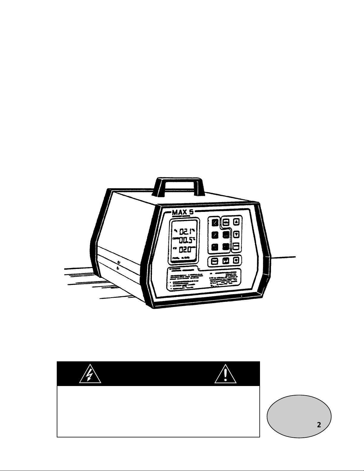
Portable Combustion Efficiency Monitor
D ANGER
HIGHLY TOXIC AND OR FLAMMABLE LIQUIDS OR GASES MAY BE PRESENT IN THIS MONITORING
SYSTEM.
PERSONAL PROTECTIVE EQUIPMENT MAY BE REQUIRED WHEN SERVICING THIS SYSTEM.
HAZARDOUS V OL TAGES EXIST ON CER T AIN COMPONENTS INTERNALLY WHICH MAY PERSIST FOR
A TIME EVEN AFTER THE POWER IS TURNED OFF AND DISCONNECTED.
ONL Y A UTHORIZED PERSONNEL SHOULD CONDUCT MAINTENANCE AND/OR SER VICING. BEFORE
CONDUCTING ANY MAINTENANCE OR SERVICING CONSULT WITH AUTHORIZED SUPERVISOR/
MANAGER.
P/N M39218
08/06/99
ECO # 99-032
Page 2
INSTRUCTION MANUAL
MAX 5
PORTABLE COMBUSTION EFFICIENCY MONITOR
SALES ORDER:
SERIAL NUMBER:
Teledyne Analytical Instruments
16830 Chestnut Street
City of Industry, CA 91748
Phone: (626) 9341500
Fax: (626) 9612538
Web: www.teledyneai.com
Page 3

TABLE OF CONTENTS
MAX 5 PORTABLE COMBUSTIBLE EFFICIENCY MONITOR
GENERAL DESCRIPTION
Introduction 1
Main Features 1
OPERATION OF CONTROLS, DISPLAYS, & INDICATIONS
Front Panel Controls 3
Back Panel Controls 4
PRINCIPLE OF OPERATION
Sensor Description 4
Temperature & Calculated Values 5
Sampling System Description 6
INSTALLATION AND START UP PROCEDURES
Precautions 9
Electronic Zeroing of Oxygen Section 10
Sensor Installation and Replacement 11
INSTRUMENT OPERATING PROCEDURE
Installation of Thermocouple 12
Initiating & Adjusting Air & Sample Flow 13
Temperature, Efficiency, & Carbon Dioxide Sections 13
Initial Calibration/Automatic Calibration 13
Manual Span (CO
& CO) 14
2
Manual Calibration (Optional) 15
Special Functions 16
Temperature Simulation 16
Cost Savings 16
To Store Readings 17
To Display Readings 17
To Print Readings (Optional) 18
To Test Keyboard 18
Automatic Data Output 18
To Print Instruction Manual 18
To Check the Version of Software 19
Electronic Zeroing of Oxygen
19
Page 4

TABLE OF CONTENTS (continued)
ROUTINE MAINTENANCE
Scrubber 19
Battery Recharging 20
Battery Replacement 20
Sensor Replacement 21
OPERATOR’S CHECKS & ADJUSTMENTS
Messages 22
Failure Warning Signs
APPENDIX
To Print Stored Readings 24a
Material Safety Data Sheets (MSDS) 24b-g
LIST OF SPARE PARTS
DRAWINGS
LIST OF FIGURES
Figure
1 Display Panel 2
2 Membrane Keyboard 2
3 Back Panel 3
4 Location of Sensors (Top View) 11
5 Sample Probe With Built-In Thermocouple 12
LIST OF TABLES
Tables
1 Detector Response To Gases 8
23
Page 5

MAX5 PORTABLE COMBUSTION EFFICIENCY MONITOR
GENERAL DESCRIPTION
INTRODUCTION
The MAX 5 Portable Combustion Efficiency Analyzer provides several special features and
applications. It directly measures oxygen, carbon monoxide, combustibles, and temperature
levels in a subject sample stream. The MAX 5 also includes microprocessor-based special
functions enabling the computer to calculate levels of carbon dioxide and combustion efficiency.
As an added bonus, the computer can calculate and display actual fuel cost savings (CompuCentsTM), by using the efficiency level prior to an adjustment, the level after an adjustment, and
an average fuel cost as reference points.
The MAX 5 incorporates an internal microcomputer. The computer program resides in ROM
(read only memory) and is not affected by shutdown periods, loss of power, or battery failure.
However, the calibration parameters and stored measurement readings are retained in RAM
(random access memory) which requires operating power to protect it; thus, the information
stored in RAM will be lost if battery power is interrupted (during battery replacement, for
example).
The computer controls the display and reads the keyboard. A 12-bit analog-to-digital (A-D)
converter converts the output signals from the various measurement sensors and the
thermocouple into digital data that goes to the computer. The computer interprets this and
compares the data to calibration data you have entered. The computer displays the corrected
values on the LCD.
Also, the computer performs error checking and reporting, as well as the other special functions
available for selection via the special function keys.
The actual program that runs the computer is compiled into machine language for faster
execution and more efficient use of memory. It is not accessible by high-level interpreters, such
as Basic, and it is not available to the user for modification in any way.
Page 6

MAIN FEATURES
1. Auto Zero. MAX 5 offers automatic zero calibration for carbon monoxide and
combustibles and automatic span calibration for oxygen. Also, you can adjust
them manually. You have to adjust the span calibration manually for carbon
monoxide and combustibles.
2. Stored Readings. The computer stores up to 20 sets of readings and reports them
to the LCD (Liquid Crystal Display) or to an optional serial printer.
3. Computer Memory. A 16-bit microprocessor and 40 kilobytes of memory are
standard.
4. ROM Instruction Manual. The MAX 5 stores an abbreviated but complete
instruction manual in ROM and prints the manual upon request.
5. Rechargeable Batteries. Nickel-cadmium batteries provide power to the unit for up
to 8 hours of continuous operation. You recharge the batteries by plugging a standard
power cord into a 115V receptacle. TBE/AI also offers 220V and 100V versions.
6. Proven Sensors. The MAX 5 uses Teledyne’s standard line of sensors, already proven
to be among the best in the instrumentation industry.
7. CO Analysis. Four ranges of CO analysis are available for the MAX 5; one standard
0-1000 ppm CO and three optional ranges - 0-500 ppm CO, 0-1% CO and 0-25% CO.
OPERATION OF CONTROLS, DISPLAYS & INDICATORS
Initial Display. Shortly after it is first switched on, the computer will test all its internal
functions and then automatically enter its normal operating mode. During this time, it will
display random segments on the LCD.
Temperature Display. Readings below 1000 degrees (Fahrenheit or centigrade) are read
directly (for example, 100 means 100 degrees). If a reading is over 1000 degrees, it will be
displayed as a number with two decimal places, and you must multiply by 1000 to get the actual
temperature. For example, 1.50 means 1.50 x 1000, or 1500 degrees.
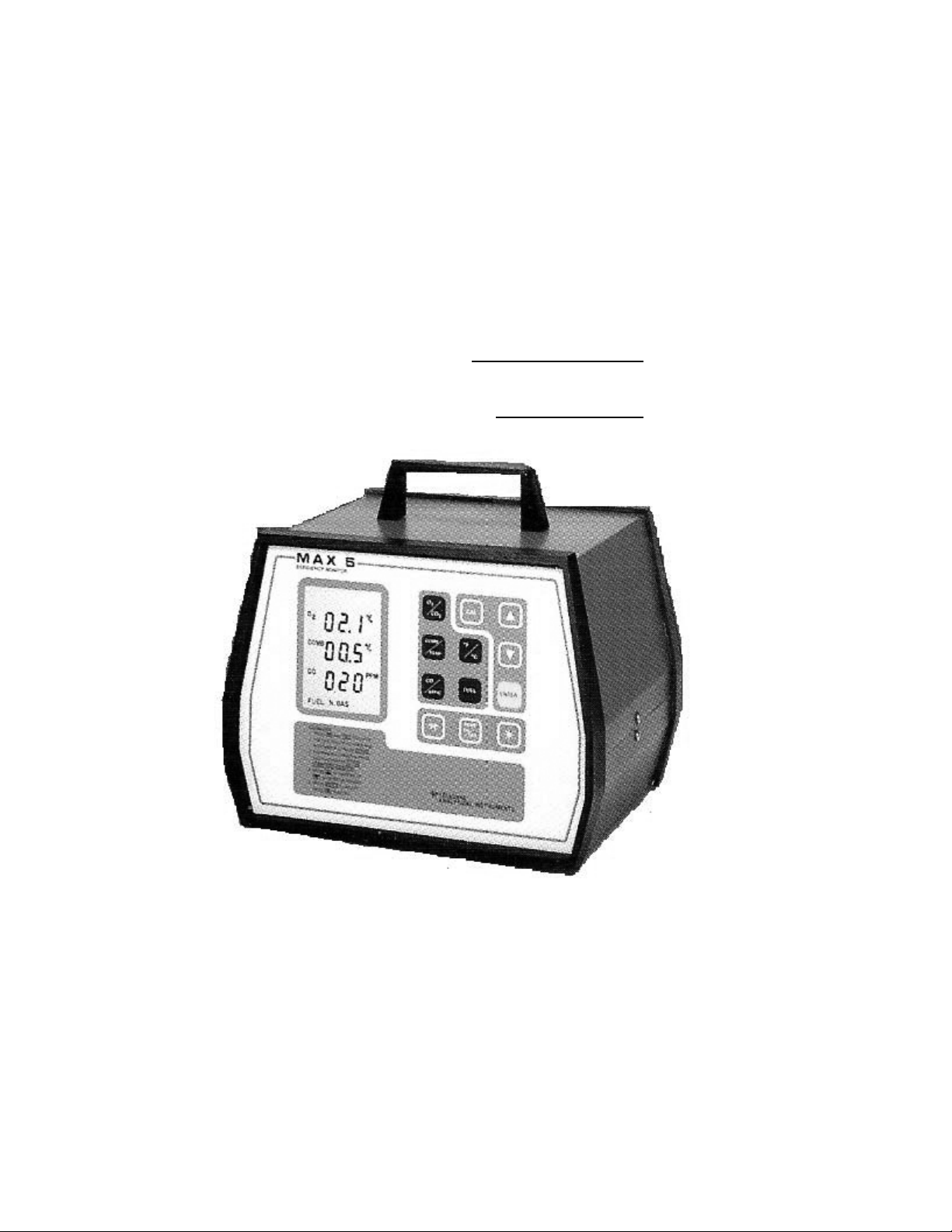
Display Panel. A continuous updated LCD monitors O
, CO, CO2, Combustibles, Temperature,
2
& Net Combustion Efficiency. The membrane keyboard includes all needed controls to select
functions; display three parameters at once, control the sampling pump, and choose degrees
Centigrade or Fahrenheit as shown in Figures 1 & 2.
(INSERT FIGURES 1 & 2)
FRONT PANEL CONTROLS
Page 7

Temp Key (°F or °C). This key, when pressed, determines which of the two available
temperature scales (toggles between degrees Fahrenheit or degrees Centigrade) will be used to
display temperature readings. See “Initial Calibration/Automatic Calibration” - “Temperature”.
O2 / CO2. Because both the oxygen and carbon dioxide readings occupy the top row of the
LCD, you press this key to display one or the other. To get a valid CO2 reading, you must select
the proper fuel (see “FUEL” below).
COMB/TEMP. You select either the combustibles or the temperature readings for display by
pressing this key. The readings appear in the center row of the display.
CO/EFFIC. You press this key to toggle between the carbon monoxide and calculated
efficiency readings. The readings appear in the bottom row of the display.
FUEL. This key is primarily used for CO2 calculation and efficiency readings. You must
choose one of the four pre-selected fuels (#2 fuel oil, #6 fuel oil, natural gas, or solid fuels such
as coal) so that the computer calculations will be valid. Pressing the FUEL key causes the fuel
selection (across the bottom of the display) to toggle through the four selections. When you see
the fuel that you are using, simply leave it that way, and the calculations will be valid for that
fuel.
CAL. Calibration is automatic for O2. MAX 5 also includes auto-zeroing for Carbon Monoxide
(CO) and combustibles, so the user need only set the spans. Calibration settings remain in
memory even when the power is off.
TELEDYNE LOGO. Used to exit from calibration procedures and used in conjunction with
calibration functions.
(INSERT FIGURE 3)
BACK PANEL CONTROLS
A. Thermocouple Connections for type “K” thermocouple supplied in probe (type “J”
optional).
B. Vent.
C. AC Power connection for recharging NiCad batteries, which provide up to eight hours
of operation.
D. Battery Power ON-OFF switch.
E. RS-232-C Serial output to provide:
* short-form Operations Manual
* up to 20 sets of stored data
Page 8

* continuous flow of all six readings
F. Air Flowmeter with flow set valve to regulate air flow.
G. Sample Flowmeter with flow set valve to regulate sample flow.
H. Chemical Scrubber for removal of corrosive compounds, such as SO2,, H2S, and NOx.
I. Sample-in Port.
J. Coalescing Filter (to remove particulates and water) and filter-drop out pot.
PRINCIPLE OF OPERATION
SENSOR DESCRIPTION
Oxygen. The oxygen section uses Teledyne’s Micro-Fuel Cell, Class B-3 oxygen sensor (U.S.
Patent No. 3,429,796). The B-3 Micro-Fuel Cell measures the concentration of oxygen in a gas
stream. The analysis is specific for oxygen; i.e., the measuring cell will not generate an output
current unless oxygen is present in the sample gas. Therefore, the oxygen channel has absolute
zero, and no zero gas is required to standardize the analyzer. The standard range is 0-25%
oxygen, and you perform span calibration with atmospheric air as the span gas, where feasible.
Carbon Monoxide. The class F-1R* solid-state electrochemical sensor measures CO. The
solid- state design eliminates leakage. You zero the CO section against air and span with a span
gas that contains the measured component in a concentration equivalent to 80-90% of the
instrument’s maximum fullscale value. TBE/AI sets the standard measurement range at 0-1000
PPM.
Combustibles. The combustibles sensor is a low-temperature, catalytic bead type transducer in
a constant current-excited Wheatstone Bridge circuit. Two legs of the bridge are exposed to the
sample gas. The other two legs are passive elements.
Gas diffuses into the sensing element and oxidizes at the catalytic surface of the active or
measuring bead, causing its temperature to rise. The reference head is not catalytically coated,
so it is not heated by the combustibles. The difference in temperature and therefore resistance of
the otherwise matched pair of catalytic beads creates a signal in the bridge circuit.
Use of the uncoated reference bead compensates for the effects of temperature variations,
humidity changes, ambient pressure changes, and variations in line resistance. The beads are
installed in a housing that has a flashback arrestor screen at the sensing aperture to prevent flame
propagation into the process.
The combustibles readout is expressed in percentage LEL (methane equivalents). Air is the zero
gas, and the span gas follows the 80-90% fullscale rule. By far the most common range is 0-5%
methane equivalence (0-100% LEL), and the span gas for that range would be 3% to 4%
Page 9

methane in nitrogen. In other cases, a hydrogen and carbon monoxide mixture might be used. In
the presence of catalyst poisons, the combustibles sensor will hold its sensitivity to a
hydrogen/CO mixture far longer than to methane; therefore, it is important to calibrate it with the
right mixture.
TEMPERATURE AND CALCULATED VALUES
Temperature. The MAX 5 uses a type “K” thermocouple. The temperature section includes
circuitry and software to linearize the thermocouple signal and provide a zero-point reference.
The temperature display reads in degrees Centigrade or degrees Fahrenheit depending on which
temperature you select.
Carbon Dioxide. Because carbon dioxide is a combustion product, and its concentration level at
any given time depends on how completely a given fuel is burned and its by-product of carbon
monoxide is oxidized, the computer is able to calculate the carbon dioxide level. The oxygen
and combustibles section readings and the fuel type you selected at the front panel are factors in
the calculation resulting in the carbon dioxide concentration on a dry basis.
*U.S. Patent No. 4,477,403; U.K. Patent No. GB21405S6B; France Patent No. 2546626.
Efficiency. The computer calculates the efficiency level. The reading, calculated from the
temperature and oxygen readings and the type of fuel selected, is not absolute; rather, it is a
relative indication of the degree of improvement achieved by adjusting the burner. The
efficiency is based on British Standards recommendations and is calculated from this formula:
Efficiency = 100--K3 -- _____K1 x T_____
K2 x (1 - O2)
21
Where: T = net temperature °C
O
= oxygen concentration %
2
K1 = fuel factor on hydrocarbon composition
K2 = theoretical maximum CO
concentration of flue gas
2
K3 = correction factor for latent heat (“wet” losses)
The values of K1, 2 and K3 for the four fuels covered by the MAX 5 are:
K1
K2 K3
Natural Gas 0.38 11.8 11.0
#2 oil 0.56 15.6 6.0
#6 oil 0.6 15.9 5.0
Coal 0.63 18.6 3.0
SAMPLING SYSTEM DESCRIPTION
Page 10

The analyzer should be inspected and calibrated each time it is used. This includes inspecting
the filter/water trap and scrubber, checking the condition of the batteries, and calibrating the
instrument.
The sample gas and the ambient temperature must be between 32° and 122°F (0° to 50°C) for the
temperature compensation to operate properly. For maximum accuracy, the analyzer should be
calibrated at the same pressure, flow rate, and temperature anticipated in the sample gas. To
minimize water condensation in the instrument, the sample gas temperature should be
approximately the same as the ambient temperature of the analyzer. The sample gas temperature
should never be more than 10°F (5°C) above the analyzer temperature.
Measurement accuracy can be affected by abrupt changes in the ambient temperature. If
possible, place the analyzer in the environment where it will be used for at least one hour before
operation. This permits temperature stabilization of the thermistor and oxygen cell. Or, if
desired, recalibrate the oxygen analyzer section in the environment where it will be used.
All sample line tubing and fittings must be leak-free. Air entering the sample line under pump
suction can dilute the sample gas to a point where errors in readings will result. The sample line
can be connected to the analyzer with a short section of tubing.
Note: Certain types of plastic tubing (e.g. silicone tubing) contain plasticizers which can leach
from the tubing and cause readings on the combustibles section of the analyzer, and in extreme
cases damage the combustible sensor.
If too short a sample line is used, the sample gas may not have sufficient time to cool, resulting
in water being condensed into the analyzer sampling system. The introduction of liquid water
into the system can damage the pumps and/or temporarily affect performance of the oxygen
sensor (cause erroneous readings, etc.) and certain other components.
If the flue gas sample contains more water than the condensate trap can reasonably handle, it
may be necessary to install a larger trap upstream of the sample intake into the analyzer.
If span gas is connected to the analyzer sample intake without the pumps operating, “coking” (or
carbonizing) of the combustible sensor will occur. In most cases, the concentration of any
particular compound you expose the combustibles sensor should not exceed the LEL (Lower
Explosive Limits) of that compound.
Response factors have been determined to relate the sensor output of a specific compound to the
output obtained using methane. Table 1 shows a list of some typical compounds and their LEL
(Lower Explosive Limits) values. To determine the output of the sensor to any of the gases
listed, compared to the same concentration of methane, multiply the MAX 5 reading obtained by
the factor listed. For example, if the output is calibrated with methane at 2%, the output for
ethylene at 2% would be 2.0% X 1.26 = 2.52% methane equivalent.
If you want to establish a reading for a particular gas, you can calibrate with that gas.
Alternately, you can calculate what the Methane equivalency is for that particular gas and
Page 11

calibrate the instrument with Methane, but make it read as if it were exposed to the gas of
interest. For example, if you calibrate with Methane and the MAX 5 reads 3%, but Propane
would read 4%, you calibrate with Methane and adjust the MAX 5 to read 4%.
TABLE 1
DETECTOR RESPONSE TO GASES
COMPOUND LEL* RESPONSE FACTOR
Methane 5.0 1.00
Hydrogen 4.0 0.86
Carbon Monoxide 12.5 0.32
Ethane 3.0 1.20
Ethylene 2.7 1.26
Acetylene 2.5 1.39
Propane 2.2 1.42
Propylene 2.0 1.33
Butane 1.9 1.54
Hexane 1.1 1.50
Cyclohexane 1.3 1.44
Heptane 1.05 1.59
Benzene 1.3 1.50
Pentane 1.5 1.45
Toluene 1.2 1.48
Ethylene Oxide 3.8 0.76
Methyl Ethyl Ketone 1.8 0.96
Methyl Acrylate 2.8 0.59
*Taken from Fire Hazard Properties of Flammable Liquids, Gases and Volatile Solids, National
Fire Protection Agency.
To determine the concentration of a compound present at the sensor from the MAX 5 reading,
when calibrated with Methane, divide the MAX 5 reading (in percent Methane) by the factor.
For example, if Ethylene is flowing by the sensor, and a MAX 5 reading of 2.0% is obtained, the
concentration of Ethylene would be:
MAX 5 Reading = 2.0% = 1.59%
Factor 1.26
For Hydrogen:
2.0
.86
For Carbon Monoxide:
2.0
= 2.32%
= 6.25%
Page 12

.32
For a mixture of 70% Hydrogen and 30% Carbon Monoxide:
0.7(2.0) + 0.3(2.0) = 3.5%
.86 .32
CAUTION
In most cases, the concentration of any particular compound that the sensor is exposed to should
not exceed the LEL of that compound or sensor damage could occur.
The concentration of combustibles should never exceed that which will react completely with the
available oxygen present in the sample (stoichiometric burning), otherwise “coking” (the
deposition of carbon from incomplete combustion) will occur at the sensor, and drift and a loss
of sensitivity will result.
Note: For compounds not listed in Table 1, consult Teledyne Brown Engineering/Analytical
Instruments.
Because of the electrochemical properties of the B-3 oxygen cell, the MAX 5 is designed for
spot checking, not continuous on-line application. The maximum continuous sampling period
should not exceed 30 minutes, followed by a 30-minute purge with atmospheric air.
INSTALLATION AND START-UP PROCEDURES
Upon receipt, of the MAX 5, inspect the entire unit for damage. If damage is found, notify the
shipper. Check unit, and included accessories, for broken or loose parts. DO NOT CONNECT
THE INSTRUMENT UNTIL ALL INSTRUCTIONS HAVE BEEN READ! If damage is
not found, check for the following parts:
* Probe
* Power Cord
* Sensor - F-1R - blue label, B-3 - orange label. (The Combustible sensor is factory installed).
* Instruction Manual
* Calibration Kit - Optional, however, required for calibration purposes.
* Printer (optional)
* Printer interface (with printer option)
* RS-232 Module (with printer option)
PRECAUTIONS
1. Do not press on the sensing surface (membrane) of the Micro-Fuel Cell sensor.
Puncturing or other damage will require replacement of the sensor.
2. The F-1R and Micro-Fuel cell sensors contain a caustic mixture, which is harmful if
touched, inhaled, or swallowed. In case of eye contact, immediately flush eyes with
Page 13

water for at least 15 minutes. Call a physician. See Material Safety Data Sheets
(MSDS).
3. The PURAFIL Media Scrubber contains Potassium Permanganate. PURAFIL Media
is non-toxic upon oral, dermal, and inhalation exposure. Breathing of the dust may cause
sneezing. Skin may feel dry after contact. PURAFIL Media is an eye irritant. In case
of eye contact, immediately flush eyes with cold water for at least 15 minutes. Call a
physician immediately. See Material Safety Data Sheet (MSDS).
4. This equipment generates, uses, and can radiate radio frequency energy and, if not
installed and used in accordance with the instruction manual, may cause interference
to radio communications. It has been tested and found to comply with the limits for
a Class A computing device pursuant to Subpart J of Part 15 of FCC Rules, which are
designed to provide reasonable protection against such interference when operated in
a commercial environment. Operation of this equipment in a residential area is likely
to cause interference, in which case, the user, at his own expense, will be required to
take whatever measures may be required to correct the interference.
5. DO NOT RUN UNIT OFF AC POWER. UNIT IS MADE FOR PORTABLE
APPLICATION - NOT CONTINUOUS LINE APPLICATION.
ELECTRONIC ZEROING OF OXYGEN SECTION
1. Turn power switch on. If a negative O2 reading is displayed proceed to step 2. If a
negative reading is not displayed, turn off unit and proceed to “Sensor Installation/
Replacement” section.
2. Press the CAL and LOGO keys simultaneously. CAL will display on the screen.
4. Press the CAL, UP and DOWN keys simultaneously. A double beep will occur
followed by a short internal and a second double beep. Electronic zeroing is now
completed.
SENSOR INSTALLATION AND REPLACEMENT
To install (or replace) the sensors in the MAX 5, proceed as follows:
1. Unplug the charging cord from the analyzer and turn power switch off. Then loosen
the two screws (no more than 3/4”) indicated on the back panel of the MAX 5.
2. Remove the upper screws on each of the MAX 5 case and lift the cover off the unit.
3. Remove the finger nuts and bracket holding the sensors in place.
NOTE: As you face the unit (keyboard toward you) the combustibles sensor is on the
far left, the CO sensor is in the center and the oxygen sensor is on the right as
Page 14

shown in Figure 4.
Figure 4. Location of Sensors (Top View)
CO SENSOR: (Refer to Interconnection Diagram)
a. Installation:
To install the F-1R sensor, remove the sensor from its protective bag
and plug it into the center receptacle in the bottom of the MAX 5. Next, take the
the connector from J6 on the analog board and plug it into the top of the F-1R
sensor.
b. Replacement
: To replace the F-1R sensor, unplug the connector from J6 at the
top of the sensor, remove the sensor by pulling up on it, and throw away the old
sensor. Take a new F-1R sensor from its protective bag, insert it into the recep tacle (center bottom of the MAX 5), and attach the connector from J6 to the top
of the sensor.
OXYGEN SENSOR: (See Interconnection Diagram)
CAUTION:
Do not scratch, puncture, or otherwise damage the Micro-Fuel Cell membrane (screen
surface). Damage to the membrane will require sensor replacement. NEVER PRESS ON
THE SENSING SURFACE (screen); you might damage the sensor.
Page 15

a. Remove the sensor from its protective bag. Carefully remove the shorting clip.
b. Pull up on the oxygen sensor holder (on the right), place the Micro-Fuel Cell
(membrane side down) onto the surface under the sensor holder, and place the
sensor holder over the cell. Be sure that the sensor is connected to J5 on the
analog board.
COMBUSTIBLES SENSOR: (Replacement Only): (See Interconnection Diagram)
a. The combustibles sensor is connected to J4 on the analog board. If the sensor
is not connected to J4 or is not present, connect it to J4 to find it in the shipping
carton. Then, remove the protective bag, connect it to J4, and plug it into the
receptacle in the bottom left side of the MAX 5.
b. To replace the combustibles sensor, remove the existing sensor from the recep tacle, detach the connector from the sensor, and throw away the old sensor.
Remove the protective bag from a new sensor, connect the sensor to J4, and
then plug the sensor into the receptacle.
6. Replace the bracket over the sensors, insert the finger nuts, and tighten them to secure
the bracket.
7. Replace the cover, insert and tighten the side screws, and tighten the screws on the back
panel.
8. Allow the unit to charge overnight to stabilize the sensors and to obtain a full charge.
CAUTION: POWER SWITCH MUST BE IN THE OFF POSITION.
INSTRUMENT OPERATING PROCEDURE
1. Plug the thermocouple connector into the back panel jack (for initial calibration) as
shown in Figures 3 & 5.
2. Turn the power switch on and allow the readings to stabilize for approximately 30
seconds.
(INSERT FIGURE 5)
INITIATING AND ADJUSTING AIR AND SAMPLE FLOW
CAUTION;
The analyzer is intended to operate at atmospheric (14.7 psi) or near-atmospheric pressure.
Page 16

If the analyzer is subject to high positive pressures, damage may occur to the pumps or
other flow systems. A regulator may be necessary upstream to maintain sample pressure
at or below atmospheric level, if you want to use this analyzer to measure a high pressure
sample.
1. Connect the probe sample line to the inlet port of the analyzer, being sure that the exhaust
port is vented to a safe area.
2. Press the PUMP ON/OFF key.
3. Adjust both flowmeters (on back panel) at 2 scfh for standard range (0-1000 ppm CO).
NOTE: For 0-2.5% CO range: Adjust the sample flowmeter to .75 scfh; set air flowmeter
2 scfh.
4. After measuring a sample gas (not more than 30 minutes), expose the inlet port to clean
dry air (be sure the pumps are still on).
5. Purge with atmospheric air for an amount of time equal to the operating time. If water
appears at the vent, purge until water no longer appears.
CAUTION:
To avoid sucking in water, turn off the pump before opening the filter drain.
6. Empty the water condensate trap, as required. If necessary, replace the filter element.
TEMPERATURE, EFFICIENCY AND CARBON DIOXIDE SECTIONS
Carbon dioxide and efficiency levels are calculated; no calibration or adjustments are necessary
here. The thermocouple section may be calibrated if desired.
INITIAL CALIBRATION and AUTOMATIC CALIBRATION (carbon monoxide and
combustibles zero, oxygen span)
1. Press the LOGO and CAL keys simultaneously. “CAL” will appear on the LCD.
2. Press ENTER for autocal; “AUTO CAL” will appear on the LCD. When all readings
are stable, a beep will sound. Press the LOGO key to exit autocal, if desired.
NOTE: If any negative readings appear, press the LOGO key to exit autocal. Proceed to the
“Manual Calibration” section.
MANUAL SPAN (carbon monoxide and combustibles span calibration)
Page 17

CAUTION: ADJUST SPAN GAS PRESSURE REGULATOR TO MINIMUM FLOW
RATE (2-3 scfh) BEFORE CONNECTING TO ANALYZER.
NOTE: To perform manual spanning of the MAX 5, the Calibration Kit is required. The
calibration kit consists of 3 gases; 2 calibration (CO & Combustible) and a background
(nitrogen).
1. For Carbon Monoxide (CO) Span:
a. Run span gas through the analyzer; adjust the span gas pressure regulator until the
analyzer’s flowmeter indicates 2.0 SCFH. NOTE: This is for standard range only
(0-1000 ppm). Set as required for optional ranges (0-1% and 0-2.5%).
b. Press the LOGO and CAL keys simultaneously, followed by CO/EFFIC, and ENTER.
A number will appear in the CO section of the LCD.
c. When the number stabilizes, use the arrow keys to change the reading, as necessary,
to agree with the span gas concentration marked on the tank. When the reading is
correct, press ENTER to store the value.
d. If the reading is very unstable, the LCD will display “bAd”.
2. For Combustibles Span: (Standard) (0-5% Comb. - % CH4).
a. Run span gas through the analyzer; adjust the span gas pressure regulator until the
analyzer’s flowmeter indicates 2.0 SCFH. Make sure the air flowmeter also reads
2.0 SCFH.
b. Press the LOGO and CAL keys simultaneously, followed by COMB/TEMP and
ENTER. A number will appear in the COMB section of the LCD.
c. When the number stabilizes, use the arrow keys to change reading as necessary, to
agree with the span gas concentration (marked on tank % CH
). When the reading
4
is correct, press the ENTER key once again to store the value.
d. If the reading is very unstable, refer to “Operator’s Checks and Adjustment” section.
3. Temperature: (Optional). If calibration of the temperature probe is desired then press
CAL and LOGO keys simultaneously, followed by the F/C key. The current temperature
reading is displayed with the word ZERO in the upper left corner. The reading may now
be changed using the arrow keys to a known temperature. Calibration is now completed!
NOTE: In the ZERO mode upward adjustment of reading may be limited to a few degrees.
Page 18

To store reading press ENTER. The word SPAN will light up on top of the LCD. For span
calibration a known higher temperature input would be required or changes to the low
temperature. So if span calibration is not desired, press ENTER to return to normal operation.
NOTE: Centigrade readings are automatically stored in memory. To store Fahrenheit readings,
press COMB/TEMP key, then press °F/°C key.
MANUAL CALIBRATION (OPTIONAL) (For Oxygen Span, CO and Combustibles Zero)
NOTE: If automatic calibration is not desired, the following manual calibration procedure
applies.
NOTE: All references to zero gas during calibration means clean ambient air.
1. Oxygen Span:
Press LOGO and CAL at the same time, then the “O2 key. A number will appear in the
“O2” section of the LCD; use the arrow keys to increase or decrease the reading as
necessary to agree with the span gas concentration (usually air at 20.9% oxygen). Press
ENTER to store the value and return to normal operation.
2. Combustibles:
Press LOGO and CAL simultaneously, then COMB. The LCD will display the current
combustibles reading and the word “ZERO” at the top. Expose the combustibles sensor
to its zero gas and use the arrow keys, as needed, to adjust the reading to the zero gas
concentration (usually zero). To accept the value press ENTER. SPAN is displayed at
the top of the LCD display. Run combustibles span gas through the instrument; use the
up or down arrow to adjust the number displayed on the LCD to match the concentration
marked on the tank (% CH4), if required. Press ENTER to store the value and return it to
the operating mode.
3. Carbon Monoxide:
Press LOGO and CAL at the same time, then CO/EFFIC. The LCD will display the
current carbon monoxide reading and the word “ZERO”. Run zero gas through the
analyzer, use the arrow keys, as needed, to adjust the reading to the zero gas con centration (usually zero). To store and proceed to manual span calibration, press
ENTER,
SPAN & WAIT is displayed at the top of the LCD. Run carbon monoxide span gas
through the instrument; use the up or down arrow keys to adjust the number displayed
on the LCD to match the concentration marked on the tank (PPM CO), if required.
Press ENTER (after WAIT message disappears) to store the value and return to the
normal operating mode.
Page 19

To restore the built in temp. calibration constants press the CAL and LOGO keys
simultaneously, then press °F/°C key. Press the CAL and COMB/TEMP keys
simultaneously. This restores the proper values and exits the calibration mode.
SPECIAL FUNCTIONS
To activate the other special functions press both the arrow keys simultaneously. The LCD will
show:
1 2 3
4 5 6
7 8 9
The numbers 1 through 9 represent the nine keys on the keypad. The “1” above represents the
“O2/CO2” key, the “9” represents the “ENTER” key, etc. The keys 1 through 9 correspond to the
special functions below.
TEMPERATURE SIMULATION
If the thermocouple probe is disconnected or bad, the display will show “OPt”, and “CELL
FAIL” at the bottom, when temperature mode is selected. If a temperature simulation is desired
press the F/C key. The “OPt” is replaced by a simulated temperature reading. To change the
temperature press LOGO and CAL keys simultaneously, followed by F/C (this key toggles
between °F & °C). The simulated temperature is displayed. Use the arrow keys to change
reading, as desired. To store reading and return to normal mode press ENTER.
COST SAVINGS
(Keys 1 and 2)
1. Press CO/EFFIC key to display efficiency on the LCD.
2. Activate Special Functions.
3. Press O2/CO2 (number 1 above); instrument will store measurement and return to the
operating mode for burner adjustments.
4. Adjust the burner for optimum conditions.
5. Press arrow keys again to resume Special Functions; then press key 2.
6. The display will read “5 0 0”; adjust with arrow keys to represent three significant
figures of an average fuel expense over some period of time. Press ENTER; the top
line of the display will show the fuel savings. The second line will show the efficiency
before adjustment, and the third (bottom) line will show the current efficiency. Press
any key to return to normal operation (previous operation will resume).
Page 20

To STORE current readings
(Key 3)
1. Activate Special Functions.
2. Press key number 3; the display will read “5 0 0”.
CAUTION: If you press ENTER while the display reads “0 0 0”, you will ERASE all
previous readings. To abort the erasing feature, simply press the LOGO key instead of
ENTER.
3. Set the display to an ID number (1 to 999 set-table) using the arrow keys.
4. Press ENTER to store the reading and the I.D. number (or Teledyne key to exit). Normal
operation will resume.
5. The readings of up to twenty burners can be stored by the above method of selecting an
I.D. number for each. Multiple readings under one I.D. number are OK (up to 20
readings
total). All 20 readings and I.D. numbers can be printed under function 5.
To DISPLAY readings that have been stored
(Key 4)
1. Activate Special Functions.
2. Press key #4. The instrument will display the first I.D. number. Press the LOGO key to
escape; and other key to proceed. The instrument will display the first set of readings.
Press any key except the LOGO key to display the second set of readings and repeat for
all readings. Press the LOGO, PUMP ON/OFF, and *keys to return to normal operation.
To PRINT stored readings
(Key 5) (Optional - See Appendix)
1. Plug the printer cable into the MAX 5 serial port and the printer. Turn on the printer.
2. Activate Special Functions and press key #5. The printer will print the I.D. number and
the six numerical values of each of the stored readings in chronological order.
To TEST the keyboard/LCD/RESET
(Key 6)
1. Activate Special Functions.
2. Press key 6 to call for a keyboard test.
Page 21

3. To test, press any key other than the LOGO or ENTER keys; to resume normal operation
press the LOGO key.
4. To perform a total memory reset press the ENTER key twice in succession.
AUTOMATIC DATA OUTPUT
(Function 7)
1. Activate Special Functions.
2. Press key 7 to activate the Data Output function.
3. Press the up or down arrow as needed to cause the display to read the desired time
interval (002 to 999 seconds) between reports. Press ENTER. A report is a continuous
transmission, through the serial port, of all six data factors (measurements and
calculations).
4. To stop data output, repeat steps 1 & 2 and set the time interval in step 3 to “000”
followed by the ENTER key.
To PRINT an instruction manual
(Key 8)
1. Connect a serial printer to the instrument’s serial port. Turn on the printer and switch
it “on-line”.
2. Activate Special Functions, then press key 8.
3. This abridged version of the instrument’s instruction manual will be printed.
-18-
To check the VERSION of your instrument’s software
(Key 9)
1. Activate Special Functions.
2. Press key number 9.
3. The display will show the model number and the month on the first line, the hour and
the date on the second line, and the year on the third line. The model, month, day, and
year correspond to the date of software release.
4. Press any key to resume normal operation.
ELECTRONIC ZEROING OF OXYGEN SECTION
Page 22

1. Turn power switch on (without O2 sensor installed). If a negative O2 reading is
displayed,
proceed to step 2. If a negative reading is not displayed, electronic zeroing is not
required.
2. Press the CAL and LOGO keys simultaneously. CAL will display on the screen.
3. Press the CAL key.
4. Press the CAL, UP and DOWN keys simultaneously. A double beep will occur followed
by a short interval and a second double beep. Electronic zeroing is now completed.
ROUTINE MAINTENANCE
WARNING: THE ELECTRONIC COMPONENTS IN THE MAX 5 CAN PRESENT AN
ELECTRICAL SHOCK HAZARD. BEFORE REMOVING THE ANALYZER COVER
FOR ANY REASON, DISCONNECT THE CHARGING CORD FROM THE POWER
SOURCE AND THE ANALYZER.
SCRUBBER
The analyzer needs the scrubber to remove interfering gases, such as sulfur and nitrogen oxides,
or hydrogen sulfide. These gases can cause false readings if they are not removed from the flue
gas sample. The scrubber is disposable and must be periodically replaced.
Replace the scrubber when its granules have changed color from purple to gray. When all traces
of purple are gone, the scrubber is not operating effectively.
To replace the scrubber, proceed as follows:
1. Obtain a new scrubber.
2. Carefully pull the old scrubber out of its bracket holder on the back of the unit.
3. The scrubber is attached to tubes on both sides; remove each end of the scrubber from
the end of each tube and throw away the old scrubber.
4. Take the new scrubber out of its plastic bag and carefully
tube.
5. Feed the tubes into the analyzer very slowly as you insert the new scrubber into its
bracket holder.
NOTE: You must be careful not to crimp the tubes when you replace the scrubber. You may
want to open the MAX 5 to check the tubing the first time you replace the scrubber.
To open the MAX 5, loosen the screws on the back, remove the top screws on the
attach the scrubber to each
Page 23

case, and lift the hood off the unit.
BATTERY RECHARGING
The rechargeable Nickel-Cadmium batteries need to be recharged after about 8 hours of use.
To Recharge the Batteries:
1. Turn the back panel power switch off.
2. Plug the power cord (connector end) into the back panel AC power receptacle and
plug the other end into the correct voltage outlet.
3. Allow the batteries to recharge for the required line power:
100VAC, 50/60 Hz - 24-30 hrs.
115VAC, 50/60 Hz - 14-16 hrs.
230VAC, 50/60 Hz - 14-16 hrs.
BATTERY REPLACEMENT
Rechargeable Nickel-Cadmium batteries last for many years; however, you may need to replace
them after a period of time. Before you replace the batteries, perform the following tests (make
sure the MAX 5 is unplugged from the wall):
To Test the Power Supply (charging circuit):
1. Open the MAX 5 as instructed in Steps 1 and 2 under the “To Replace Batteries” section
below.
2. Locate R39 resistor.
3. Put test meter leads across R39 resistor. The reading should be 40 mVDC +2 mVDC
when you plug the AC power cord into the wall.
4. If you get the correct reading in step 3, this indicates that the charging circuit is okay.
To Test the Batteries:
1. Unplug the MAX 5 from the wall.
2. Put the red lead from the test meter to J2 pin 1 (red) and the black lead to J2 pin 2
(green). The reading should be approximately 7.5 VDC. Move red lead to J2 pin 3
(black). The reading should be approximately -5 VDC. If your readings do not equal
these, replace the batteries (see “To Replace Batteries” section below).
Page 24

To Replace Batteries:
1. Loosen the screws indicated on the back panel of the MAX 5.
2. Remove the upper and lower screws on the outside of the MAX 5 housing and remove
both panels of the MAX 5. Disconnect J2 from the analog PCB (smaller PCB assy.).
3. Remove the screw holding the battery pack in place. Carefully lift out the battery pack.
4. Remove the tape and plate holding the existing batteries in place. Replace the batteries
with new Nickel-Cadmium rechargeable batteries.
5. Tape the new batteries in place and replace the plate. Insert the battery pack in the
MAX 5 and screw it in place. Reconnect J2 to analog PCB. Put on the bottom of the
case, insert and tighten the screws on the sides and tighten the screws in the back of
the MAX 5.
SENSOR REPLACEMENT
When the sensor’s (CO, Comb., and O2) near the end their useful life, sensitivity will decline
rapidly and the readings will be very unstable. Refer to “Operator’s Checks & Adjustment” -
Messages and Failure Warning Signs for further details. For sensor replacement, refer to
“Installation Procedures.”
AFTER REPLACING ANY SENSOR, PROCEED TO THE “INSTRUMENT OPERATING
PROCEDURE” SECTION FOR CALIBRATION.
Important: To avoid the possibility of not having a replacement cell available when it is
needed, Teledyne recommends that a spare cell be ordered shortly after the instrument is placed
in service, and each time the cell is replaced thereafter.
Caution:
instrument should be in reserve.
OPERATOR’S CHECKS & ADJUSTMENTS
MESSAGES
This section describes messages that may appear on the MAX 5 LCD so that you can correct the
problem.
DO NOT OVER ORDER (OR STOCKPILE) SPARE CELLS. Only one cell per
-0.0 Indicates a negative reading. A bad sensor, a downward shift in zero calibration since the
last adjustment, or an improper calibration might produce this error message.
REMEDY:
Recalibrate the instrument.
Page 25

-0.00/-0.0 The negative sign in a reading of -0.00 or -0.0 in the CO or COMB section after
auto zero is not significant.
bAd Indicates a bad reading from the cell. If the cell is outside its specifications or is noisy
and unstable, the computer cannot get a good reading, and the calibration adjustment required to
compensate may be greater than the maximum allowable adjustment, resulting in this error
message. REMEDY: Recalibrate the instrument or replace the cell.
CELL FAIL Means that a cell has failed or that a problem has occurred in a sensor circuit.
REMEDY: Isolate the faulty sensor circuit, replace the bad sensor, or rectify the circuit
problem, as necessary. Example: Thermocouple is not connected.
- - - Means that the value cannot be calculated. If the thermocouple is disconnected, for
example, then the computer cannot perform the efficiency calculation (which depends on
temperature data), and this error may occur; the efficiency reading will be - - -, and the
temperature reading will be OPt.
OFF Means off-scale for CO reading.
LO BATT Indicates the batteries are depleted or near depletion after about 8 hours use.
REMEDY: Recharge the batteries.
FAILURE WARNING SIGNS
The MAX 5 indicates failure warning signs with a CELL FAIL message on the LCD and a bAd
reading.
O2 The cell output is low which results in too high a span requirement.
CO The inability to span or excessive noise indicate cell failure.
COMB. Excessive drift and the inability to span or zero indicate cell failure.
TEMP. A failure message on the temperature section indicates an open or short
thermocouple circuit.
CO
Conditions that contribute to failure or erroneous reporting of the carbon dioxide section
2
include failure of any of the other sensors or incorrect fuel selection.
OPt Open thermocouple or optional temperature simulation (Refer to “Temperature
Simulation” section).
Page 26

APPENDIX
TO PRINT STORED READINGS (KEY 5) - OPTIONAL
1. On the back of the instrument is a “serial output” receptacle for connection to a serial
(RS-232C) printer (see Note). The RS-232C data output format is as follows: 1 start
bit, 8 data bits, and 1 stop bit, at a rate of 300 baud (bits/sec.). A connecting cable is
available from TBE/AI when using a standard serial printer with the analyzer. To use
the printer, proceed as follows:
Plug the cable into the MAX 5 “serial output” receptacle and the printer
(see Figure 3).
Align the paper.
Turn the power on.
Press the “FF (Form Feed)/Auto Sheet Load” button to advance the paper one
sheet.
Press the “ONLINE” button.
NOTE: If the printer is purchased from TBE/AI, refer to the printer “instruction manual” for set
up. If the printer is not purchased from TBE/AI, any serial printer may be used if it complies
with the following minimum specifications:
a. It can accept RS-232C serial data in the speed and format shown.
b. It has a standard 25 pin RS-232C connector, so it can be used with the
optional factory-supplied cord).
c. It has a minimum print speed of 50 characters per second (cps).
d. It has an input buffer of at least 1024 bytes (1Kb).
Page 27

MATERIAL SAFETY DATA SHEET
Section I - Product Identification
Product Name: Micro-Fuel Cells, all classes except A-2, A-3, A-5, B-2F and B-2VF.
Electrochemical Oxygen Sensors, all classes except R-19.
Mini Micro-Fuel Cells, all classes.
Manufacturer: Teledyne Brown Engineering/Analytical Instruments
Address: 16830 Chestnut Street, City of Industry, CA 91749
Phone Number: (818) 961-9221
MSDS Prepared By: Chuck Molloy
Date Prepared or Last Revised: 3-31-88
Emergency Phone Number: (818) 961-9221
Section II - Physical and Chemical Data
Chemical and Common Names: Potassium Hydroxide (KOH) 15%
Granular Lead (Pb) pure
CAS Number: KOH 1310-58-3
Pb 7439-92-1
Melting Point/Range: -10 to 0 deg. C.
Boiling Point/Range: 100 to 115 deg. C
Specific Gravity: 1.09 @ 20 deg. C
pH: >14
Solubility in Water: Completely soluble
Percent Volatiles by Volume: None
Appearance and Odor: Colorless, odorless solution
Page 28

Section III - Physical Hazards
Potential for Fire and Explosion: The electrolyte in micro-fuel cells is not flammable. There are
no fire to explosion hazards associated with micro-fuel cells.
Potential for Reactivity: The sensors are stable under normal conditions of use. Avoid contact
between the sensor electrolyte and strong acids.
Section IV - Health Hazard Data
Primary Route(s) of Entry: Ingestion, Eye/Skin Contact
Exposure Limits: OSHA PEL .05 mg/cu.m. (Pb)
ACGIH TLV 2 mg/cu.m. (KOH)
Effects of Overexposure:
Ingestion: The electrolyte could be harmful or fatal if swallowed.
Oral LD50 (RAT) = 2433 mg/kg
Eye: The electrolyte is corrosive and eye contact could result in permanent
loss of vision.
Dermal: Liquid inhalation is unlikely.
Signs/Symptoms of Exposure: Contact with skin or eyes will cause a burning sensation and/or a
soapy feeling for skin contact.
Medical Conditions Aggravated by Exposure: None
Carcinogenicity:
NTP Annual Report on Carcinogens: Not listed.
LARC Monographs: Not listed.
OSHA: Not listed
Other Health Hazards: Lead is listed as a chemical known to the State of California to cause
birth defects or other reproductive harm.
Page 29

Section V - Emergency and First Aid Procedures
Eye Contact: Flush eyes with water for at least 15 minutes and get immediate medical attention.
Skin Contact: Wash affected area with plenty of water and remove contaminated clothing. If
burning persists, seek medical attention.
Ingestion: Give plenty of cold water. Do not induce vomiting. Get medical attention.
Inhalation: Liquid inhalation is unlikely.
SECTION VI - HANDLING INFORMATION
Handling Precautions: Note: The oxygen sensors are sealed and under normal circumstances,
the contents of the sensors do not present a health hazard. The following information is given as
a guide in the event that a cell leaks.
Protective Clothing: Rubber gloves, chemical splash goggles.
Clean-up Procedures: Wipe down the area several times with a wet paper towel. Use a fresh
towel each time.
Protective Measures during Cell Replacement: Before opening the bag containing the cell,
check the cell for leakage. If the cell leaks, do not open the bag. If there is liquid around the cell
while in the instrument, put on gloves and eye protection before removing the cell.
Disposal: Should be in accordance with all applicable state, local and federal regulations.
Page 30

MATERIAL SAFETY DATA SHEET
Section I - Product Identification
Product Name: Carbon Monoxide Sensor, Class F-1R, F-1RH and F-2
Manufacturer: Teledyne Brown Engineering/Analytical Instruments
Address: 16830 Chestnut Street, City of Industry, CA 91749
Phone Number: (818) 961-9221
MSDS Prepared By: Chuck Molloy
Date Prepared or Last Revised: 3-31-88
Emergency Phone Number: (818) 961-9221
Section II - Physical and Chemical Data
Chemical and Common Names: Sulfuric Acid (H2SO4) 17%
Silica (SiO
) 50%
2
CAS Number: H2SO4 7664-93-9
SiO
7631-86-9
2
Melting Point/Range: 1700 deg. C
Boiling Point/Range: N/A
Specific Gravity: 2.2 @ 20 deg. C
pH: Less than 1
Solubility in Water: Insoluble
Percent Volatiles by Volume: None
Appearance and Odor: White powder with an irritating odor.
Page 31

Section III - Physical Hazards
Potential for Fire and Explosion: The electrolyte in carbon monoxide sensors is not flammable.
There are no fire or explosion hazards associated with carbon monoxide sensors.
Potential for Reactivity: The sensors are stable under normal conditions of use. Avoid contact
between sensor electrolyte and strong acids, strong bases, strong oxidizers and reducers.
Primary Route(s) of Entry: Ingestion, Eye/Skin Contact
Exposure Limits: OSHA PEL N/A
ACGIH TLV 1 mg/cu.m. (H2SO4)
10 mg/cu.m. (Total Dust)
5 mg/cu.m. Respirable Dust (SiO2)
Effects of Overexposure:
Ingestion: The electrolyte could be harmful or fatal if swallowed.
Oral LD50 (RAT) = 2433 mg/kg
Eye: The electrolyte is corrosive and eye contact could result in permanent
loss of vision.
Dermal: The electrolyte is corrosive and skin contact could result in a chemical
burn.
Inhalation: Solid inhalation is unlikely.
Signs/Symptoms of Exposure: Contact with skin or eyes will cause a burning sensation.
Medical Conditions Aggravated by Exposure: None
Carcinogenicity:
NTP Annual Report on Carcinogens: Not listed
LARC Monographs: Not listed
OSHA: Not listed.
Other Health Hazards: None
Page 32

Section V - Emergency and First Aid Procedures
Eye Contact: Flush eyes with water for at least 15 minutes and get immediate medical attention.
Skin Contact: Wash affected area with plenty of water and remove contaminated clothing. If
burning persists, seek medical attention.
Ingestion: Give plenty of cold water. Do not induce vomiting. Get medical attention.
Inhalation: Solid inhalation is unlikely.
Section VI - Handling Information
Handling Precautions: Note: The carbon monoxide sensors are sealed and under normal
circumstances, the contents of the sensors do not present a health hazard. The following
information is given as a guide in the event that a cell leaks.
Protective Clothing: Rubber gloves, chemical splash goggles.
Clean-up Procedures: Wipe down the area several times with a wet paper towel. Use a fresh
towel each time.
Protective Measures during Cell Replacement: Before opening the bag containing the cell,
check the cell for leakage. If the cell leaks, do not open the bag. If there is liquid around the cell
while in the instrument, put on gloves and eye protection before removing the cell.
Disposal: Should be in accordance with all applicable state, local and federal regulations.
Page 33

RECOMMENDED SPARE PARTS LIST
MAX 5 MONITOR
P/N DESCRIPTION
QTY.
1 C-6689-B3 MICRO-FUEL CELL - OXYGEN SENSOR
1
* C-40371-F1R ELECTROCHEMICAL SENSOR - CO (01000 PPM STD.)
1 A-39202A COMBUSTIBLE PROBE/CABLE
1 B-39764A PROBE GUN ASSEMBLY (TYPE “K” HI TEMP.
THERMOCOUPLE)
1 B-39764B PROBE GUN ASSEMBLY (TYPE “J” LO TEMP.
THERMOCOUPLE)
1* D-38370A PC BOARD ASSEMBLY - ANALOG (TYPE “K”
THERMOCOUPLE)
1* D-38370B PC BOARD ASSEMBLY - ANALOG (TYPE “J”
THERMOCOUPLE)
1* D-38584A PC BOARD ASSEMBLY - MICROPROCESSOR
1 L-182 LCD DISPLAY
10 F-6 FUSES, 3AG, 1/4A
5 B-71 NiCAD BATTERIES
1 C-964 POWER CORD
1 B-64942 PUMP ASSY
1 F-273 SAMPLE FLOWMETER
1 F-274 AIR FLOWMETER
1 B-25900 SCRUBBER
1 A-13455 FILTER ELEMENT
1 F-513 FILTER ASSY
1 A-40688 CAL KIT FOR 0-1000 PPM CO; Replacement CAL Gas G-222
1 A-48231 CAL KIT FOR 0-1% CO; Replacement CAL Gas G-41 & G-259
(CO)
1 A-48232 CAL KIT FOR 0-2% CO; Replacement CAL Gas G-41 & G-162
(CO)
1 C-967 CARRYING CASE (MAX)
1 P-528 PRINTER
1 I-106 INTERFACE for printer
1 A-40342 PRINTER CABLE ASSEMBLY (for printer)
1 T-823 TRANSFORMER (used w/printer for 220V application only)
*Specify CO range when ordering.
A MINIMUM CHARGE IS APPLICABLE TO SPARE PARTS ORDERS.
IMPORTANT: Orders for replacement parts should include the part number (if available) and
the model and serial number of the system for which the parts are intended.
Page 34

SEND ORDERS TO:
TELEDYNE Analytical Instruments
16830 Chestnut Street
City of Industry, CA 91748
Telephone: (626) 9341500
Fax: (626) 9612538
Web: www.teledyneai.com
or your local representative.
Page 35

REFERENCE DRAWINGS
MAX 5 MONITOR
INSTALLATION DRAWINGS
B-39437 OUTLINE DIAGRAM
B-39430 PIPING DIAGRAM (STANDARD)
B-43108RF PIPING DIAGRAM (%CO) (OPTIONAL)
C-39776 CONNECTION DIAGRAM
ASSEMBLY DRAWING
A-40342 ASSEMBLY - PRINTER CABLE
Page 36

(INSERT DRAWINGS)
 Loading...