

Page 1
1
Introduction
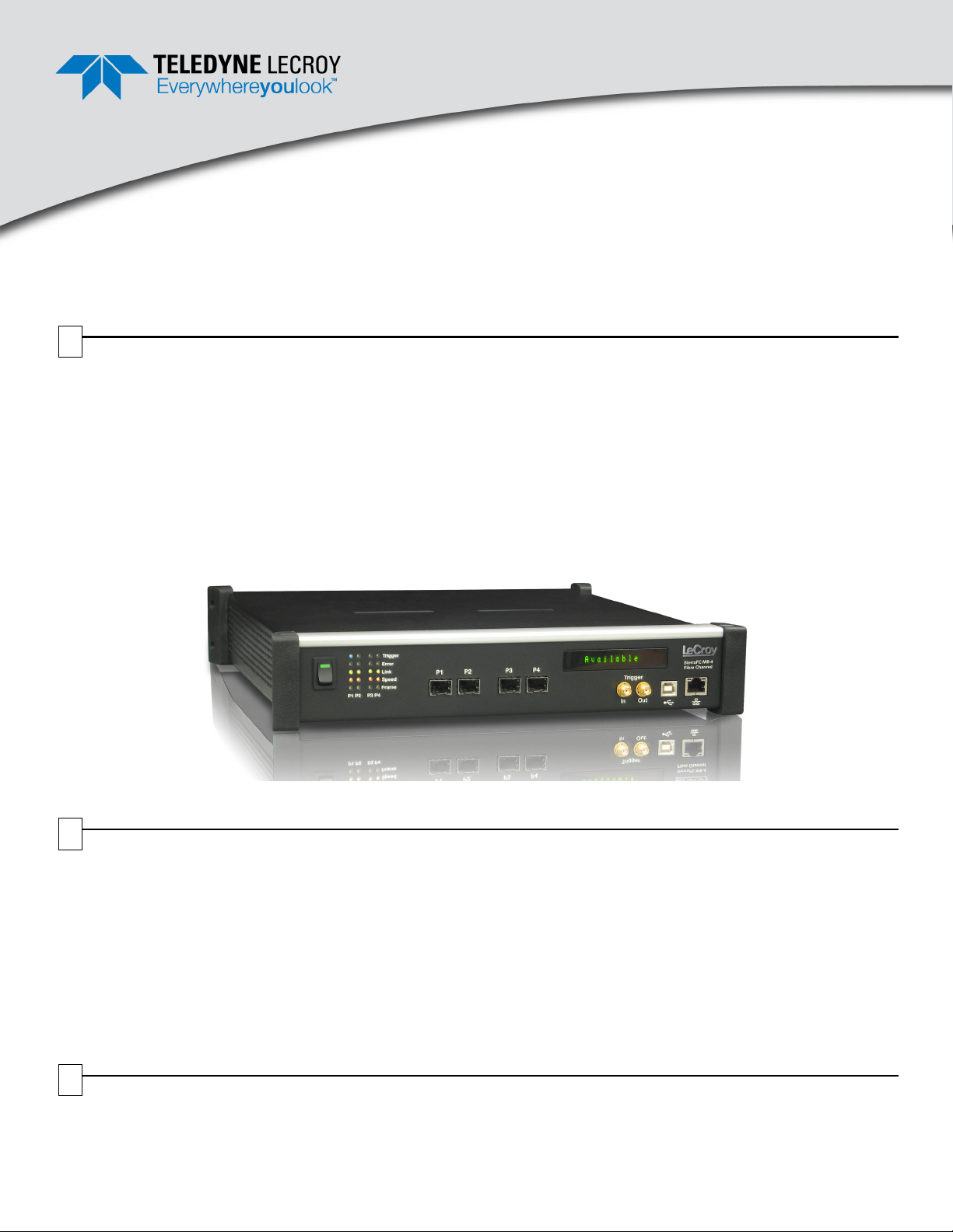
The SierraFC M8-4 Fibre Channel Protocol Analyzer helps
Hardware, Firmware, Design, and Application Engineers
troubleshoot and diagnose problems within their product.
The analyzer supports capture, triggering, and filtering.
SierraFCM8-4
Quick Start
Before Starting
Use this document for quick installation and setup. If you
experience problems or need more information, see the
SierraFC M8-4 User Manual on the Installation CD or at the
Teledyne LeCroy web site. For details about the latest software
version, see the Readme file on the Installation CD.
The Analyzer has a USB port and an Ethernet port to
connect to a computer. You can cascade analyzer units for
higher port counts. You can trigger manually or trigger on a
specific event.
The Analyzer provides for bi-directional trigger and capture
of exchanges, primitives, and patterns. You can capture all
frames and/or exclude traffic. The Analyzer provides a full
range of views and statistical reports.
SierraFC M8-4 Protocol Analyzer
2
Components
The analyzer package includes the following components:
• SierraFC M8-4 Analyzer identified in the packing list
• SierraFC M8-4 Quick Start
• USB A-B 2.0 cable, 1.8 meter
• Ethernet cable, 10 feet
• DB9(male) to DB9(female) extension cable, 6 feet
• Three-Prong AC power cord
• Installation CD ROM with software and documentation
The software installs on Microsoft
Windows Vista, and Windows 7. Please see the Readme
file on the installation CD for the latest information on PC
requirements.
Please see the SierraFC M8-4 User Manual on the
installation CD for component specifications and further
details.
®
Windows® XP,
3
Unpacking the Analyzer
Inspect the received shipping container for any damage. Unpack the container and account for each of the system
components listed on the accompanying packing list. Visually inspect each component for absence of damage.
In the event of damage, notify the shipper and Teledyne LeCroy Corporation. Retain all shipping materials for shipper’s
inspection.
Page 2
Front Panel Description
612 91075483
11
4
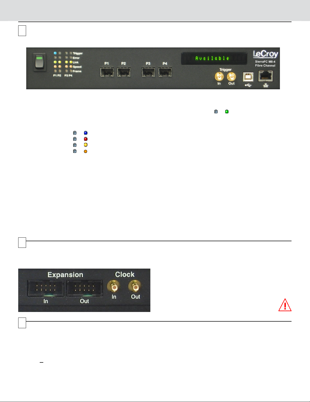
Features
The Analyzer has the following features on the front:
• Power Switch [1]
• LED Indicators for P1-P2 and P3-P4 [2]
• Tri gger or for trigger
• Error or for error
• Link or for link
• Speed or for speed level,
with two LEDs per FC port pair.
• Speed LEDs are off when there is no link.
• If only P1 or P2 (or P3 or P4) has valid traffic, the LED pair
shows the port speed.
• If P1 and P2 (or P3 and P4) have separate link speeds, the
LED pair toggles between the port speeds.
• If P1 and P2 (or P3 and P4) successfully link, the LED pair
shows the link speed, according to the following table:
Speed P1 (P3) P2 (P4)
1 Gbps Off Off
2 Gbps Off On
4 Gbps On Off
8 Gbps On On
• Frame or for traffic
After the link, indicates traffic on
the bus.
• Port 1 connector [3]
• Port 2 connector [4]
• Port 3 connector [5]
• Port 4 connector [6]
• External Trigger Input (Trigger IN) [7]
• External Trigger Output (Trigger OUT) [8]
• USB Port for host connectivity [9]
• Ethernet Port for network connectivity [10]
• Status and Configuration LCD Display [11]
5
Expansion Connectors
The Analyzer provides cascading features through the
STX Sync Expansion card on the back.
6
Installing the Software
1. Insert the Installation CD ROM into the CD drive on the host machine. The installation automatically starts setup,
unless Auto Run is off. In that case, select the CD ROM from “My Computer” and click Setup.
After the warning to close all other programs and before starting the installation, the Install component selection opens.
2. Select components for installation.
3. Click N
4. Restart the computer before using the software.
Note: If you get an error message during installation of the drivers, consult your system administrator.
ext to complete the installation. The SierraFC M8-4 software installs on the PC hard disk.
You can use cascading of analyzer units for higher port
counts, by daisy chaining the units through the STX SYNC
Expansion Card on the analyzer back.
For expansion, see the Introduction chapter of the
SierraFC M8-4 User Manual.
Warning: Do not open the enclosure. No operator
serviceable parts are inside.
Page 3

Setting Up and Connecting
Analyzer
I1 T1 I2 T2
HBAs
Hard Drives
cables
cables
7
Note: You must install the software before connecting the
analyzer to the host machine for the first time.
To set up the analyzer:
1. Connect the analyzer to a 100V–240V, 50Hz–60Hz,
power outlet and turn on the Power switch.
At power on, the analyzer will go through initialization
as shown on the LCD display.
2. Connect the USB cable between the SierraFC M8-4
USB port and a USB port on the Host PC. The host PC
operating system detects the analyzer and driver files.
(See section 8 for how to connect via Ethernet.)
Connect from Hard Drives using SFP and a cable
suitable for your setup.
Connect from HBAs using SFP and a cable suitable for
your setup.
For an illustration of the cabling, see the Introduction
chapter of the SierraFC M8-4 User Manual.
3. Connect the analyzer to P1/P3 and/or P2/P4:
Starting the Application
8
To launch the software, double-click the FC Icon in the Program Manager Window. After you start
the software, click on Configuration and select All Connected Devices (see screen capture on
the right) to display the Select Device dialog. Click Refresh Device List (see screen captures
below) to display all the devices on the network. Select a device and click Connect.
Operating in Simulation Mode
The system operates in Simulation Mode by default, if the software detects no hardware. However, you can operate in
Simulation Mode directly, without installing the Analyzer hardware.
To start using the protocol analyzer and software, see the Protocol Analyzer chapter of the SierraFC M8-4 User Manual.
Page 4

DHCP Address
Static Address
9
Connecting via Ethernet
The Ethernet connection can have any of these configurations:
Connecting to a Network using a Hub, Switch, GigE interface, or Similar Device
When connected to a network, the analyzer can communicate with the DHCP server to establish a connection. The DHCP
server continually sends the next available IP address to the analyzer until the software starts.
Note: To connect using a different subnet or for remote operation, see the Introduction chapter of the SierraFC M8-4 User
Manual.
Connecting to a Host Computer using a Hub, Switch, GigE interface, or Similar Device
When connected to the host machine using a hub, switch, GigE interface, or similar device, the Analyzer must
communicate with the host computer to establish a connection. The host computer continually broadcasts the next
available IP address to the Analyzer, until the software starts.
IP_Address: When you start the software, the Internet Protocol (TCP/IP) Properties dialog may prompt you to
automatically use the offered IP address or to assign a specific IP address. (The assigned IP address must be on the same
network segment as the host computer.)
The software searches for all analyzers connected to the network and displays a list of available units in the Find Devices
dialog. After you select a unit, the software assigns the IP address to the selected unit, completing the connection, then
launches the software.
Connecting Directly to the Host Computer using a Cable
Connect SierraFC M8-4 to the Host PC using an Ethernet cable.
Connecting Via USB
To set up the Analyzer using a USB connection, connect the USB port to a USB port on the PC using a USB cable.
Turn on the rear power switch and the front power switch. Click Next after you see the Add New Hardware Wizard window.
Follow the Microsoft® Windows® on-screen Plug-and-Play instructions for the automatic installation of the Analyzer as a
USB device on your PC.
10
Operating the SierraFC M8-4 System
The SierraFC M8-4 application can perform protocol analysis.
To use the software for protocol analysis, first select File > Protocol Analyzer for a new project protocol analysis .fcc file.
(You can also open a .fcs sample file from the Examples folder.)
1. In Easy Mode, on the Capture tab, select to capture Everything or Pattern. For Pattern, select a Pattern. You can
exclude patterns and frames. You can use different patterns for pre-trigger and post-trigger.
2. In Easy Mode, on the Trigger tab, select the trigger type. For Pattern, select the pattern.In Easy Mode, on the Settings
tab, select trigger position and memory use.
3. Change the Analyzer settings if necessary. Change the port Speed if necessary.
4. Use Advanced Mode only after you become familiar with the hardware and software and have special needs.
To change viewer options and see more detail about operation, see the Introduction chapter of the SierraFC M8-4 User
Manual.
Teledyne LeCroy Customer Support
Online Download
Periodically check the Teledyne LeCroy Protocol Solutions Group web site
for software updates and other support related to this product.
Trademarks and Servicemarks
Teledyne LeCroy and SierraFC M8-4 are trademarks of Teledyne LeCroy
Corporation. Microsoft and Windows are registered trademarks of Microsoft Inc.
All other trademarks are property of their respective companies.
Mail: 3385 Scott Blvd., Santa Clara, CA 95054-3115
Web: http://www.teledynelecroy.com/tm/Library/software/PSG
E-mail: psgsupport@lecroy.com
Tel: (800) 909-7112 (USA and Canada)
Tel: (408) 653-1260 (worldwide)
Fax: (408) 727-6622 (worldwide)
Changes
Product specifications are subject to change without notice.
Teledyne LeCroy reserves the right to revise the information in this document
without notice or penalty.
Teledyne LeCroy © 2012. All rights reserved. Part Number: 917990-00 Rev. C
This document may be printed and reproduced without additional permission, but all copies should contain this copyright notice.
 Loading...