

Page 1
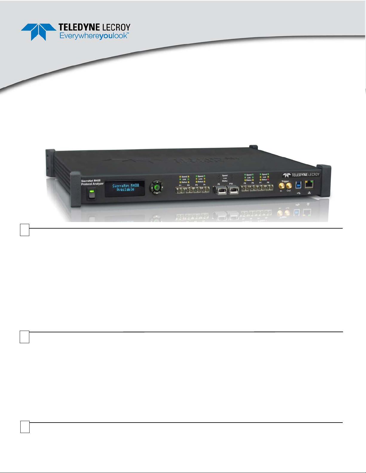
SierraNet™ M408
Quick Start
Before Starting
Use this document for quick installation and setup. If you
experience problems or need more information, see the
SierraNet M408 User Manual on the Installation CD-ROM or at the
Te ledyne LeCroy web site. For details about the latest software
version, see the Readme file on the Installation CD-ROM.
1
Introduction
The SierraNet M408 analyzer is Teledyne LeCroy's 10 Gigabit Ethernet, 40 Gigabit Ethernet and 16 Gigabit Fibre Channel
Analyzer and Jammer platform. It has eight SFP+ 10 GigE / 16G FC and two QSF P 40 GigE por ts. Up to 64 GB of capture
memory allows for capturing of extensive line-speed data
The SierraNet M408 ports allow signals to pass through without re-timing, ensuring that the test platform is as transparent
as possible. The analyzer can be controlled either via a one (1) Gigabit Ethernet connection to the local network or via a
USB 3.0 (up to 5 Gb/s) connection. The SierraNet M408 provides the user with easy-to-understand control panel and LED
indicators.
Major features of the M408 include triggering on back-to-back events, use of counters within trigger conditions, and
multi-state (up to 24) triggering and filtering state machines with four transitions per state.
The Net Protocol Suite software for controlling the analyzer and displaying the captured data installs on the latest
Microsoft
®
Windows®. See the Readme file for the latest information on host-machine requirements.
Components
2
The analyzer package includes the following components:
SierraNet M408 Analysis platform
USB 3.0 cable, 1.8 meter
1 Gigabit Ethernet cable, 10 feet
AC power cord
Installation CD-ROM with software and documentation
This Quick Start guide
Unpacking the Analyzer
3
Inspect the received shipping container for any damage. Unpack the container and account for each of the system
components listed on the accompanying packing list. Visually inspect each component for absence of damage.
In the event of damage, notify the shipper and Teledyne LeCroy. Retain all shipping materials for shipper’s inspection.
Please see the SierraNet M408 User Manual on the
installation CD-ROM for component specifications and
further details.
Page 2
Front Panel Description
23 896
1
10 1157
111
1
4
4
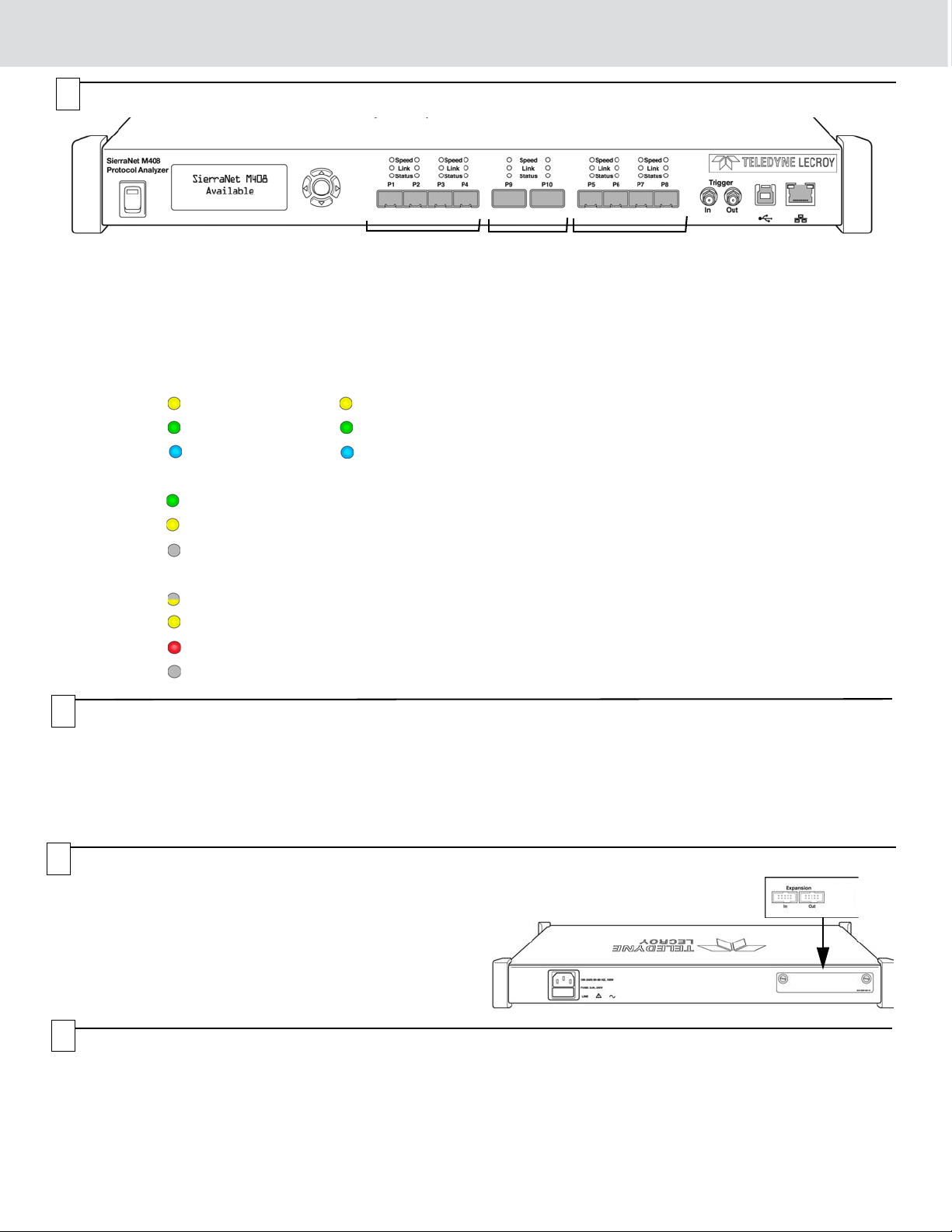
Features
The Analyzer has the following features on the front:
[1] LED Indicators for P1-P4, P5-P8 and P9-P10 for S peed ,
Link and Status
Speed LEDs
The LEDs for SPEED illuminate as follows:
GBE Fibre Channel
Yellow Reserved 4G/2G/1G FC
Green 10 GigE 8G FC
Blue
Link Activity LEDs
Green Network activity Detected
Yellow Link up, no activity
No Color No link
Status LEDs
Yellow Blinking Waiting for trigger
Yellow Solid Triggered
Red Error detected
No Color No Activity
40 GigE 16G FC
Please see the SierraNet M408 User Manual for details on
the LEDs.
[2] Power Switch
[3] Status and Con fig uration LCD Display
[4] Front Panel 5-Buttons keypad
[5] SFP+ 10 GigE / FC connectors for ports 1-4
[6] QSFP+ 40 GigE connectors for ports 9-10
[7] SFP+ 10 GigE / FC connectors for ports 5-8
[8] External Trigger Input (Trigger In)
[9] External Trigger Output (Trigger Out)
[10] USB Port for host connectivity
[11] Ethernet Port for network connectivity
Front Panel Buttons
5
The following parameters can be viewed and/or configured directly on the front panel, using the display and 5 button keypad:
- Display of IP address
- Display of model name: “SierraNet M408”
- Connection status
- Display of unit name
6
Rear Panel Description Expansion Slot
The analyzer expansion slot at the back of the SierraNet M408
system can accommodate different Expansion cards, like the
SYNC Expansion Card that can be used to daisy-chain multiple
analysis systems or the Power Expansion Card that can provide
and control power to devices under test.
Note: Do not open the enclosure except for adding expansion
cards. No user serviceable parts are inside.
7
Installing the Software
1. Insert the Installation CD-ROM into the CD drive on the host machine. The installation automatically starts setup,
unless Auto Run is off. In that case, select the CD-ROM from “My Computer” and click Setup. Follow the instructions to
complete the installation. Once installation is complete the SierraNet M408 Protocol will reside on the host machine’s
non-volatile drive (whether hard disk or SSD-based).
2. Restart the computer before using the software.
Note: If you get an error message during installation of the drivers, consult your system administrator.
- IP configuration
• IP mode dynamic, or
•IP mode static
Page 3

Setting Up and Connecting
8
Note: You must install the software before connecting the
analyzer to the host machine for the first time.
To set up the analyzer:
1. Connect the analyzer to a 100V–240V, 50Hz–60Hz,
power outlet and turn on the Power switch.
At power on, the analyzer will go through initialization
as shown on the LCD display.
2. Connect the USB cable between the SierraNet M408
USB port and a USB port on the host machine. The
host machine operating system detects the analyzer
and loads the driver files. (See Section 10 for how to
connect via Ethernet.)
Starting the Application
9
To launch the software, select Start > All Programs > LeCroy > Net Protocol Suite. Select Setup
> Device Management (see screen capture on the right) to display the Device Management
dialog. Click Refresh Device List (see screen captures below) to display all the devices on the
network. Select a device and click Connect.
3. Connect your devices using SFP+ optics and a fiber
cable suitable for your setup.
4. Connect the 10 GigE or Fibre Channel devices to po rt
pairs P1/P2, P3/P4, P5/P6 and/or P7/P8 and connect
40 GigE devices to port pair P9/P10.
For an illustration of the cabling, see the Introduction
chapter of the SierraNet M408 User Manual.
Operating in Simulation Mode
The system operates in Simulation Mode by default, if the software detects no hardware. However, you can operate in
Simulation Mode directly, without installing the analyzer hardware.
To start using the protocol analyzer and software, see the Protocol Analyzer chapter of the SierraNet M408 User Manual.
Page 4

DHCP Address
Static Address
10
The SierraNet M408 platform can be connected to the host machine by using either a USB cable (as described in Section
8) or by using a1 GbE connection as described below.
Connecting via Ethernet
When using Ethernet, the SierraNet must communicate with the host machine to establish a connection .
To connect to the Ethernet network the Sierra M408 should be assigned an IP address. The IP address can be assigned
automatically, if the network has a DHCP server, or assigned manually using either the front-panel keypad and display or
the Net Protocol Suite software.
IP Address Configuration
The IP address can be configured either via the front panel buttons o r using the application when the a nalyzer is connected
to the host machine via a USB cable.
When connected to a network, the analyzer can communicate with the DHCP server in order to obtain its IP address
configuration.
Connecting the Platform to the Host Machine via Ethernet
Once the IP Address is configured, the SierraNet M408 analyzer is automatically detected by the application if the analyzer
and the host machine on which the application is running are on the same Ethernet subnet. A list of all available units are
displayed in the Find Devices dialog.
If the analyzer and the host machine are located on different subnets then the IP address of the analyzer needs to be
configured manually in the application: Use the Add Device feature by clicking th e Add Device button in the Select Device
window.
11
It is recommended that you read the SierraNet M408 User Manual before operating the system, to get familiar with the
capabilities and settings. Also, we recommend that you initially use the ‘Easy Mode’ on the Capture tab to set the capture
parameters.
Getting Started with Protocol Analysis
To use the SierraNet M408 software for protocol analysis, select File > New Project for a new protocol analyzer project or
open one of the sample projects from the Examples folder (look for a .get file).
Teledyne LeCroy Customer Support
Online Download
Periodically check the Teledyne LeCroy Protocol Solutions web
site for software updates and other support related to this product.
Operating the SierraNet M408 System
Mail: 3385 Scott Blvd., Santa Clara, CA 95054-3115
Web: teledynelecroy.com/tm/Library/software/PSG
E-mail: psgsupport@teledynelecroy.com
Tel: (800) 909-7112 (USA and Canada)
Trademarks and Servicemarks
LeCroy and SierraNet M408 are trademarks of Teledyne LeCroy.
Microsoft and Windows are registered trademarks of Microsoft Inc.
All other trademarks are property of their respective companies.
© 2012 Teledyne LeCroy, Inc. All rights reserved. Part Number: 922143-00 Rev. C
This document may be printed and reproduced without additional permission, but all copies should contain this copyright notice.
Changes
Product specifications are subject to change without notice.
T eledyne LeCroy reserves the right to revise the information in this
document without notice or penalty.
 Loading...