

Teledyne m1280, m2050, m2020, m2590, m2450 User Manual
...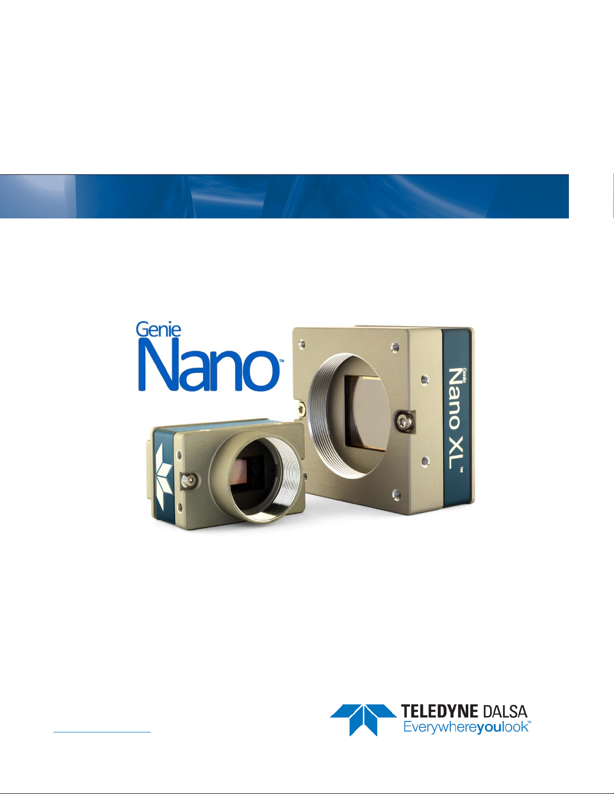
Genie Nano Series
™
Camera User’s Manual
Monochrome
& Color GigE Vision Area Scan
May 3, 2017
Rev: 0015
P/N: G3-G00M-USR00
www.teledynedalsa.com
sensors | cameras | frame grabbers | processors | software | vision solutions

Notice
© 2015-2017 Teledyne DAL SA
All information provided in this manual is believed to be accurate and reliable. No responsibility is
assumed by Teledyne DALSA for its use. Teledyne DALSA reserves the right to make changes to
this information without notice. Reproduction of this manual in whole or in part, by any means, is
prohibited without prior permission having been obtained from Teledyne DALSA.
Microsoft and Windows are registered trademarks of Microsoft Corporation in the United States and
other countries. Windows, Windows 7, Windows 10 are trademarks of Microsoft Corporation.
All other trademarks or intellectual property mentioned herein belong to their respective owners.
Document Date: May 3, 2017
Document Number: G3-G00M-USR00
About Teledyne DALSA
Teledyne DALSA is an international high performance semiconductor and electronics company that
designs, develops, manufactures, and markets digital imaging products and solutions, in addition
to providing wafer foundry services.
Teledyne DALSA Digital Imaging offers the widest range of machine vision components in the
world. From industry-leading image sensors through powerful and sophisticated cameras, frame
grabbers, vision processors and software to easy-to-use vision appliances and custom vision
modules.

Nano Series GigE Vision Camera Contents • 1
Contents
GENIE NANO SERIES OVERVIEW 8
DESCRIPTION 8
GigE with TurboDrive 8
Genie Nano Overview 9
GigE Firmware 9
PART NUMBERS AND SOFTWARE REQUIREMENTS 10
Monochrome Ca m e ras 10
Color Cameras 12
Accessories 15
Teledyne DALSA Development Software 16
Third Party GigE Vision Development 16
About GigE Vision 16
GENIE NANO COMMON SPECIFICATIONS 17
Sensor Cosmetic Specifications 19
Dynamic Range & Signal to Noise Ratio Test Conditions 20
EMI, Shock and Vibration Certifications 20
Mean Time Between Failure (MTBF) 21
MODEL SPECIFICATIONS: M/C1940 & M/C1920 22
Spectral Response 24
MODEL SPECIFICATIONS: M/C2020, M/C2050 25
MODEL SPECIFICATIONS: M/C2420, M/C2450 26
Spectral Responses 27
MODEL SPECIFICATIONS: M/C4060, M/C4040 28
Spectral Responses 29
MODEL SPECIFICATIONS: M/C4030, M/C4020 30
Spectral Responses 31
MODEL SPECIFICATIONS: M/C640, M/C800, M/C1280, M/C1930, M/C2590 32
Spectral Response 35
MODEL SPECIFICATIONS: NANO XL – M/C 5100, M/C 4090 36
Spectral Response 38
MODEL SPECIFICATIONS: C4900 39
Spectral Response 40
Model C4900 Sensor Cosmetic Specifications 41
Guide to Using a Rolling Shutter Camera 42
Characteristics 42
Overview of Ele c tr onic Rolling Sh utter (ERS) Exposures 43
Overview of Global Reset Relea s e ( G R R ) Exposures 44
COMPARISON OF SIMILAR ON-SEMI AND SONY SENSORS 45
NANO QUICK START 47
TESTING NANO WITHOUT A LENS 47
TESTING NANO WITH A LENS 47
THE CAMERA WORKS — NOW WHAT 47
CONNECTING THE GENIE NANO CAMERA 48
GIGE NETWORK ADAPTER OVERVIEW 48
PAUSE Frame Support 48

2 • Contents Nano Series GigE Vision Camera
CONNECT THE GENIE NANO CAMERA 48
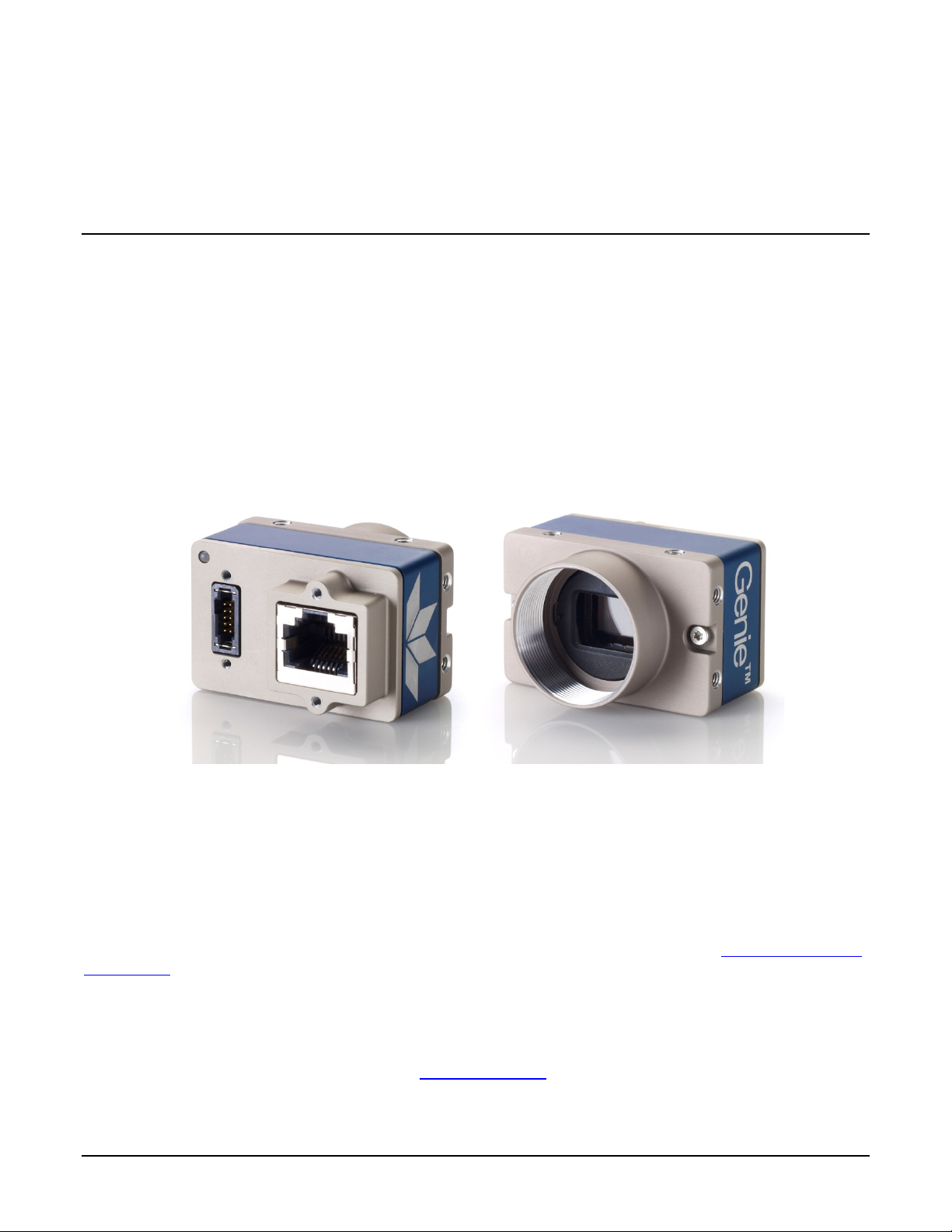
Connectors 49
LED Indicators
50
Camera Status LED Indicator 50
LED States on Pow er Up 50
Genie Nano IP Configuration Sequence 51
Supported Networ k Configurations 51
PREVENTING OPERATIONAL FAULTS DUE TO ESD 52
USING NANO WITH SAPERA API 53
NETWORK AND COMPUTER OVERVIEW 53
INSTALLATION 54
Procedure 54
Camera Firmware Updates 54
Firmware via Linux or Third Party Tools 54
GigE Server Verification 55
GigE Server Status 55
OPTIMIZING THE NETWORK ADAPTER USED WITH NANO 56
QUICK TEST WITH CAMEXPERT (WINDOWS) 56
About the Device User ID 57
OPERATIONAL REFERENCE 58
USING CAMEXPERT WITH GENIE NANO CAMERAS 58
CamExpert Panes 58
CamExpert View Para meter s O ption 59
CAMERA INFORMATION CATEGORY 60
Camera Information Feature Descriptions 60
Power-up Configuration Dialog 64
Camera Power-up Configuration 64
Load / Save Configuration 64
SENSOR CONTROL CATEGORY 65
Sensor Control Feature Descriptions 66
Offset/Gain Control Details (Sony sensors) 69
Sony Sensors Gain Stage Diagram 69
Offset/Gain Control Details (On-Semi Python sensors) 70
On-Semi Python Sensors Gain Stage Diagram 70
Bayer Mosaic Pattern 71
OnSemi Sensor Artifacts with Fast Readout Mode 71
Fast Readout Mode A r tifacts Correc tion 72
Exposure Alignment: Overview 72
Synchronous Exposure Alignment 72
Reset Exposure Alignment 72
Sensor Exposure Timing: Sony Sensor Models 73
Trigger Characteristics: Start of Exposure 73
Sensor Exposure Timing: OnSemi Python Models 74
Trigger Characteristics: Start of Exposure 74
AUTO-BRIGHTNESS CONTROL CATEGORY 75
Auto-Brightness Feature Descriptions 75
Using Auto-Brightness 77
General Preparation 77
Auto-Brightness with Frame Luminance Averaging 78
Auto-Gain 78
Auto-Brightness by using Auto-Exposure and Auto-Gain 78
I/O CONTROL CATEGORY 79
I/O Control Feature Descriptions 80

Nano Series GigE Vision Camera Contents • 3
I/O Module Block Diagram 84
Trigger Mode Details 84
Trigger Source Types (Tr igger Mode=On) 84
Input Line Details 85
Trigger Overlap: Feature D eta ils 86
Output Line Detai ls 93
Output High an d Ou tput Low Block Diagra m
93
COUNTER AND TIMER CONTROL CATEGORY 94
Counter and Timer Control Feature Description 94
Counter and T im er Group Block Diagram 98
Example: Counter Start Source = OFF 99
Example: Counter Start Source = CounterEnd (itse lf) 99
Example: CounterStartSource = EVENT and Signal (Edge Base) 100
Example: CounterStar tS ou r c e = Line (Edge Base) Example 100
ADVANCED PROCESSING
C
ONTROL CATEGORY 101
Advanced Processing Control Feature Descriptions 101
Lookup Table (LUT) Overview 104
LUT Size vs. Outp ut Pixel
Format 104
Defective Pixel Replacement 105
Example User Defective Pi xel Map XML File 105
Monochrome Def ective Pixel Replac e ment Algorithm D escription 106
Color Defective P ixel Replacement Algorithm Description 108
COLOR PROCESSING CONTROL CATEGORY 109
Color Processing Control Feature Description 109
Color Processing Functional Overview 110
White Balance O pe r a tion 111
Simplified RGB De s ig n Firmware Block Diagram 111
Saturation an d L uminance Operati on 112
FLAT FIELD CORRECTION CATEGORY 113
Flat Field Correction Feature Description 113
CYCLING PRESET MODE CONTROL CATEGORY 115
Cycling Preset Mode Control Feature Description 116
Using Cycling Presets—a Simple Example 120
Multi-Exposure Cy c lin g Example S etup 120
Cycling Reset Timing Details 121
Case 1: Cycling with Internal Synchronous Increment 121
Case 2: Cycling with External Asynchronous Increment 121
Using Cycling Presets with Output Controls 122
Feature Settings for this Example 122
Cycling Mode Constraints with a changing ROI 123
Specifics Concerning OnSemi Sensor Models 123
Specifics Conc erning Sony Sensor Models 123
IMAGE FORMAT CONTROL CATEGORY 124
Image Format Control Feature Description 125
Width and Height Features for Partial Scan Control 130
Vertical Cropping (Partial Sca n) 130
Maximum Frame Rate Examples (Models M/C 1920 & 1940) 131
Maximum Frame Rate Examples (Models M2420 & M2450) 131
Maximum Frame Rate Examples (Models M2020 & M2050) 132
Maximum Frame Rate Examples (Models M/C 4040 & 4060) 132
Maximum Frame Rate Examples (Models M/C 4020 & 4030) 133
Maximum Frame Rate Examples (Model M/C 2590) 133
Maximum Frame Rate Examples (Model C 4900) 134
Maximum Frame Rate Examples (Model M/C 1930) 135
Maximum Frame Rate Examples (Model M/C 1280) 135
Maximum Frame Rate Examples (Model M/C 800) 136
Maximum Frame Rate Examples (Model M/C 640) 136

4 • Contents Nano Series GigE Vision Camera
Maximum Frame Rate Examples (Nano XL–M5100) 137
Maximum Frame Rate Examples (Nano XL–M4090) 138
Horizontal Cropping (Partial Scan) 139
Using the Multiple ROI Mode 139
Important Usage D etails 140
Example: Two H or izontal ROI Areas (2x1) 140
Example: Four ROI Areas (2x2) 141
Example: Actual Sample with Six ROI Areas (3x2) 141
Horizontal and Vertical Flip 143
Image Flip – Full Frame 143
Image Flip – Multi-ROI Mode 144
Binning Function and Limitations 145
Horizontal Binning Constraints 145
Vertical Binning Constraints 145
Internal Test Pattern Generator 146
METADATA CONTROL
CATEGORY
147
Metadata Control Category Feature Descriptions 147
Metadata Notes: 150
Extracting Metadata Stored in a Sapera Buffer 151
ACQUISITION AND TRANSFER CONTROL CATEGORY 153
Acquisition and Transfer Control Feature Descriptions 154
Acquisition B uffering 155
Using Transfer Queue Current Block Count with CamExpert 156
Features that Cannot be Changed During a Transfer 156
ACTION CONTROL CATEGORY 157
Action Control Feature Descriptions 158
GigE Vision Action Command Refer ence 158
Nano Features s upporting Action C om m a nd 158
EVENT CONTROL CATEGORY 159
Event Control Feature Descriptions 160
Basic Exposure Events Overview 164
Events Assoc ia ted with Triggered Synch r on ous Exposures 165
Events Associated with T r iggered M ultiple Frame Synch r on ous Exposures 165
Overview of Precision Time Protocol Mode (IEEE 1588) 166
PTP Master Cloc k Identity 166
An Example with two Nano Cameras 166
IEEE 1588 Reference Resources 167
Examples using Timestamp Modulo Event for Acquisitions 167
Case Examples Overv iew 167
Case 1: Simple Repeating Ac quisitions as Upcoming Events 167
Case 2: Potential Uncertainnes s to the Start Time 168
Case 3: Timer Reset before the Actual Star t Time 169
Case 4: Timer Res et a fter the Actual S tart Time 170
Case 5: Changin g ‘timestampModulo’ d uring Acquisitions 171
GIGE VISION TRANSPORT LAYER CONTROL CATEGORY 172
GigE Vision Transport Layer Feature Descriptions 172
Defaults for devicePacketResendBufferSize 177
GIGE VISION HOST CONTROL CATEGORY 178
Teledyne DALSA TurboDrive 178
FILE ACCESS CONTROL CATEGORY 178
File Access Control Feature Descriptions 179
Updating Firmware via File Access in CamExpert 182
Overview of the deviceUserBuffer Feature 182
IMPLEMENTING TRIGGER-TO-IMAGE RELIABILITY 183
OVERVIEW 183

Nano Series GigE Vision Camera Contents • 5
T2IR with Genie Nano 183
NANO FEATURES FOR T2IR MONITORING 183
SAPERA TOOLS FOR NETWORKING 185
NANO IP CONFIGURATION MODE DETAILS 185
TECHNICAL SPECIFICATIONS 186
MECHANICAL SPECIFICATIONS — C & CS MOUNT: 186
MECHANICAL SPECIFICATIONS — NANO XL: 188
ADDITIONAL NOTES ON GENIE NANO IDENTIFICATION AND MECHANICAL 189
Temperatur e Ma n ag ement 189
SENSOR ALIGNMENT SPECIFICATION 189
CONNECTORS 190
10-pin I/O Connector Details 190
Camera DC Power Characteristics 191
I/O Mating Connector Sources 191
Power over Ethernet (PoE) Support 191
Input Signals Electrical Specifications 192
External Input Details 192
External Input DC Characteristics 192
External Inpu t AC Timing Character istics 193
External Inpu ts: Using TTL/LVTTL Drivers 193
External Inputs: Using Common Collector NPN Driv e r s 194
External Inpu ts: Using Common Emitte r NPN Driver 194
External Inputs: Using a Balanced Driver 195
Output Signals Electrical Specifications 195
External Output Details and DC Characteristics 195
External Output AC Timing Characteristics 196
External Outputs: Using Extern al TTL/LVTTL Drivers 197
External Outputs: Using Extern al LED Indicators 197
Using Nano Outputs to drive other Nano Inputs 199
COMPUTER REQUIREMENTS FOR NANO CAMERAS 200
Host PC System 200
Recommended Network Adapters 200
Ethernet Switch Requirements 201
IEEE 802.3x Pause Fram e Flow Control 201
Ethernet to Fiber-Optic Interface Requirements 201
EC & FCC DECLARATIONS OF CONFORMITY 202
Models: M/C1920, M/C1940 202
Models: M/C2590, M/C1930, M/C1280, M/C800, M/C640 203
Models: M/C2020, M/C2050, M/C2420, M/C2450 204
Models: M/C4020, M/C4030, M/C4040, M/C4060 205
Models: M/C5100, M/C4090 206
ADDITIONAL REFERENCE INFORMATION 207
CHOOSING A LENS WITH THE CORRECT IMAGE CIRCLE 207
Lens Options for Models ‘M/C1940’ & ‘M/C1920’ 207
Lens Options for Models ‘2450/2420’ & ‘2050/2020’ 208
Lens Options for Models ‘4060/4040/4030/4020’ 208
Lens Options for XL Models ‘M/C 5100’ and ‘M/C 4090 209
Lens Options for Model ‘C4900’ 210
Lens Options for Models ‘M/C2590’ 210
Lens Options for Models ‘M/C1930’ 211
Lens Options for Models ‘M/C1280’ 211

6 • Contents Nano Series GigE Vision Camera
Lens Options for Models ‘M/C800’ 212
Lens Options for Models ‘M/C640’ 212
Additional Lens Parameters (application specific) 213
OPTICAL CONSIDERATIONS 213
Illumination 213
Light Sources 214
IR Cut-off Filters 214
Nano Models with Built-in IR Cut-off Filters 214
Guidelines for Choosing IR Cu t-off Filters 214
Back Focal Variance when using any Filter 215
LENS MODELING 217
Magnification and Resolution 217
SENSOR HANDLING INSTRUCTIONS 218
Electrostatic Discharge and the Sensor 218
Protecting Against Dust, Oil and Scratches 218
Cleaning the Sensor Window 219
RUGGEDIZED
CABLE ACCESSORIES
219
Cable Assembly G3-AIOC-BLUNT2M 220
Cable Assembly G3-AIOC-BRKOUT2M 222
Components Express Right-Angle Cable Assemblies 224
Cable Assembly: Right-Angle I/O Bunt End 224
Cable Assembly: Right-Angle I/O to Euro B lock 225
Ruggedized RJ45 Ethernet Cables 226
Components Ex pr e s s Contact Inf or mation 226
Cable Assembly: Right-Angle Ethernet 227
Right-Angle Cable-Set (Mounted) 228
TROUBLESHOOTING 229
OVERVIEW 229
Problem Type Summary 229
Verifying Network Parameters 231
Before Contacting Technical Support 231
DEVICE AVAILABLE WITH OPERATIONAL ISSUES 231
Firmware Updates 231
Power Failure During a Firmware Update–Now What? 232
Cabling and Communication Issues 232
Acquisition Error without Timeout Messages 232
Grab has Random Bad Data or Noise 233
No camera exposure when ex pec ted 233
Camera is func tional but frame rate is lower than expected 234
Camera acquis ition is good but fr a m e r a te is lower than expected 234
Camera is functional, frame rate is as expected, but image is black 234
Other Problems or Issues 235
Preventing Dropped Packets by adjusting Power Opti on s 235
Random Invalid Trigger Events 235
Minimum Sapera Version Requ ired 236
Issues with uninstalling Cognex VisionPro with S a p er a LT CamExpert 236
ADDENDUMS 237
AC CHARACTERISTICS: “1 INPUT / 3 OUTPUT” MODELS 237
REVISION HISTORY 238
CONTACT INFORMATION 239
SALES INFORMATION 239

Nano Series GigE Vision Camera Contents • 7
TECHNICAL SUPPORT 239
INDEX 240
8 • Genie Nano Series Overview Nano Series GigE Vision Camera
Genie Nano Series Overview
Description
The Genie Nano series, a member of the Genie camera family, provides a new series of affordable
easy to use digital cameras specifically engineered for industrial imaging applications r equiring
improved network integration.
Genie Nano cameras use the industries’ latest leading sensors such as the Sony Pregius series and
On-Semi Python series of global shutter active pixel-type CMOS image sensors.
Genie Nano
cameras combine standard gigabit Ethernet technology (supporting GigE Vision 1.2)
with the Teledyne DALSA Trigger-to-Image
-Reliability framework to dependably capture and
transfer images from the camera to the host PC. Genie Nano
cameras are available in a number of
models implementing different sensors, image resolutions, and feature sets, either in monochrome,
monochrome NIR, or color versions.
GigE with TurboDrive
Genie Nano cameras include TurboDrive™ technology, delivering high speed data transfers
exceeding the GigE l imit. TurboDrive uses advanced data modeling to boost data transfers up to 2
or 3 times faster than standard GigE Vision speeds – with no loss of image quality. These
breakthrough rates are achieved using a proprietary process that assembles data from the sensor
to optimize throughput, simultaneously taking full advantage of both the sensor’s maximum frame
rate and the camera’s maximum GigE data transfer speed (up to 115 Mbytes/s). Teledyne DALSA’s
TurboDrive increases system dependability and robustness similar to Camera Link throughput on a
GigE network.
Important: Actual Transfers with TurboDrive is image content dependent but in the best case
scenario, transfers over a GigE Network can reach the camera’s internal acquisition limit of up to
252MB/sec. If transfers are less than the camera maximum acquisition rate, camera memory will
be used as a circular frame buffer. Refer to TurboDrive Primer on the Teledyne DALSA web site for more
details.

Nano Series GigE Vision Camera Genie Nano Series Overview • 9
Genie Nano Overview
• Optimized, rugged design
with a wider operating temperature
• Availa ble in multiple sensors/resolutions, monochrome and color
• Higher frame rates with Teledyne DALSA GigE Vision TurboDrive Technology
• Visual camera multicolor status LED on back plate
• Multi-ROI support
• 2 (default models) general purpose opto-coupled inputs
• 2 (default models) general purpose opto-coupled outputs (user, counter, or timer driven for
Strobe and Flash triggering)
• Counter, Timer, and Events available to support imaging applications
• Cycling mode supports 64 multiple camera setups (including Multi-Exposure)
• Supports Image Time-Stamp based on IEEE1588-2008 (PTP: Precise Time Protocol) or an
Internal Timer
• Programmable Look-Up-Table (LUT) available
• Defective Pixel replacement available on some models
• Multicast and Action Command supported
• Image metadata supported
• Supports Pow e r Ove r Ethernet (PoE) or auxiliary power input
• Implements 32 MB of Flash Memory
• 2 User Settings sets to store and recall camera configurations
• Supports the Gigabit Ethernet PAUSE Frame feature
• GigE Vision 1.2 compliant
• Gigabit Ethernet (GigE) interconnection to a computer via standard CAT5e or CAT6 cables
• Gigabit Ethernet (GigE) transfer speed up to 115 MB/second
• Application development with the freely available Sapera™ LT software libraries
• Native Teledyne DALSA Trigger-to-Image Reliability design framework
• Refer to the Operation Reference and Technical Specifications section of the manual for full
details
• Refer to the Sapera LT 8.10 release notes for information on GigE Vision and TurboDrive
Technology su p p o rt .
GigE Firmware
Firmware updates for Genie Nano are available for download from the Teledyne DALSA web site
www.teledynedalsa.com/imaging/support/downloads. Choose Genie Nano Firmware from the
available download sections, then choose the zip file download specific to your camera model.
When using Sapera LT, update the camera firmware using CamExpert (see File Access via the
CamExpert Tool).
The Camera firmware can also be easily upgrade/downgrade within your own application via the
API. The camera has a failsafe scheme which prevents unrecoverable camera errors even in the
case of a power interruption.

10 • Genie Nano Series Overview Nano Series GigE Vision Camera
Part Numbers
and Software Requirements
This manual covers the released Genie Nano monochrome and color models summarized in the two
tables below. These tables list models in increasing resolution. Nano common specifications and
details for each Genie Nano model follow these tables.
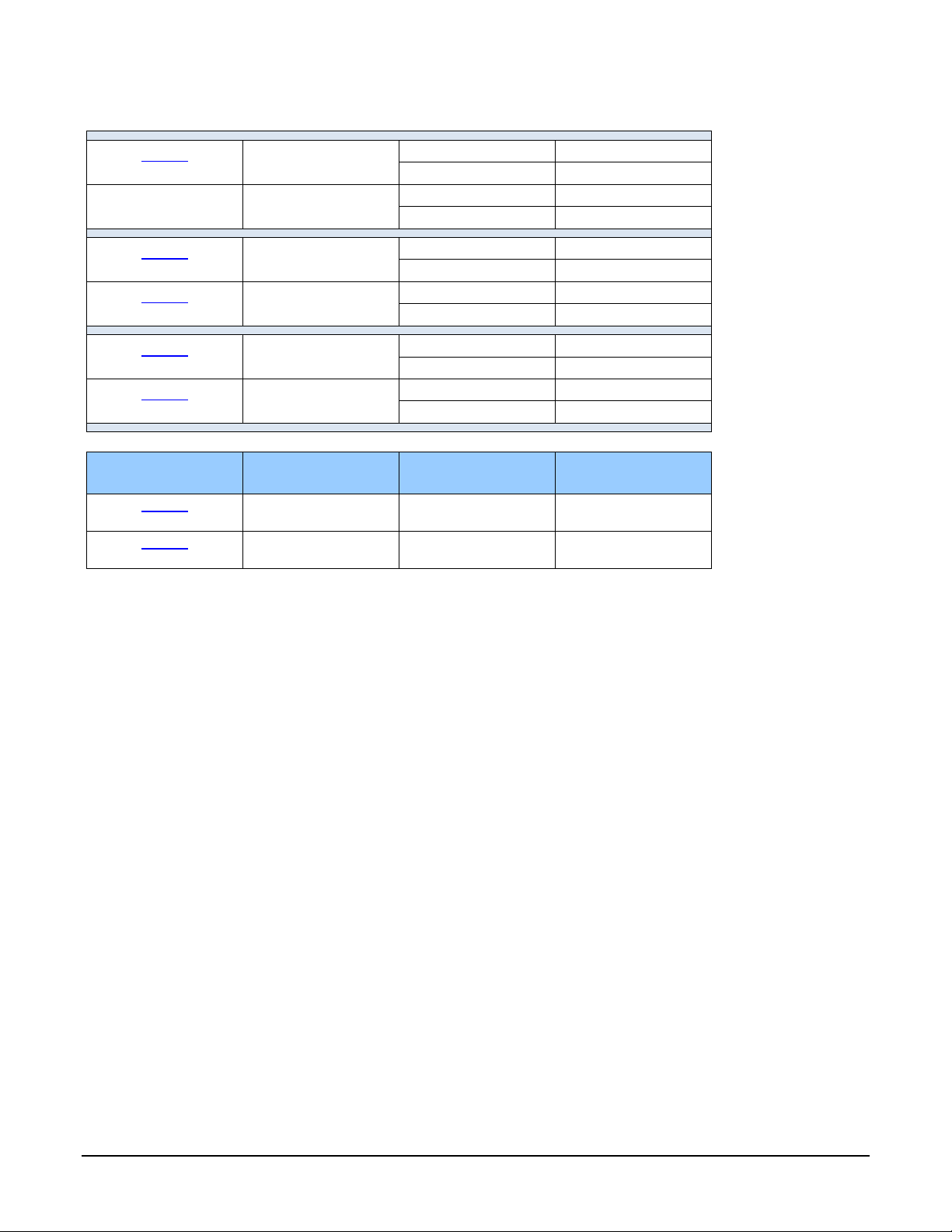
Monochrome Cameras
Model
Full Resolution
Sensor Size/Model
Lens
Part Number
M640
672 x 512
On-Semi 0.3M
(Python300)
C-mount
G3-GM10-M0640
CS-mount
G3-GM10-M0641
M640 NIR
672 x 512
On-Semi 0.3M
(Python300
)
C-mount
G3-GM12-M0640
CS-mount
G3-GM12-M0641
M800
832 x 632
On
-Semi 0.5M
(
Python500)
C-mount
G3
-GM10
-M0800
CS-mount
G3-GM10-M0801
M800 NIR
832 x 632
On-Semi 0.5M
(
Python500)
C-mount
G3-
GM12-M0800
CS-mount
G3-GM12-M0801
M1280
1280 x 1024
On-
Semi 1.3M
(Python1300
)
C-mount
G3
-GM10-M1280
CS-mount
G3-GM10-M1281
M1280 NIR
1280 x 1024
On-Semi 1.3M
(Python1300
)
C-mount
G3-GM12-M1280
CS-mount
G3-GM12-M1281
M1930
1984 x 1264
On-Semi 2.3M
(Python2000)
C-mount
G3
-GM10-M1930
CS-mount
G3-GM10-M1931
M1930 NIR
1984 x 1264
On-Semi 2.3M
(Python2000)
C-mount
G3-GM12-M1930
CS-mount
G3-GM12-M1931
M1940
1936 x 1216
Sony 2.3M
(IMX174)
C-mount
G3-GM10-M1940
CS-mount
G3-GM10-M1941
M1920
1936 x 1216
Sony 2.3M
(IMX249)
C-mount
G3-
GM11
-M1920
CS-mount
G3-GM11-M1921
M2050
2048 x 1536
Sony 3.2M
(IMX252)
C-mount
G3-GM10-M2050
CS-mount
G3-GM10-M2051
M2020
2048 x 1536
Sony 3.2M
(IMX265)
C-mount
G3-GM11-M2020
CS-mount
G3-GM11-M2021
M2450
2448 x 2048
Sony 5.1M
(IMX250)
C-mount
G3-GM10-M2450
CS-mount
G3-GM10-M2451
M2420
2448 x 2048
Sony 5.1M
(IMX264)
C-mount
G3-GM11-M2420
CS-mount
G3-GM11-M2421
Nano Series GigE Vision Camera Genie Nano Series Overview • 11
Monochrome Cameras Continued
M2590
2592 x 2048
On-Semi 5.1M
(
Python5000)
C-mount
G3
-GM10-
M2590
CS-mount
G3-GM10-M2591
M2590 NIR
2592 x 2048
On-Semi 5.1M
(Python
5000)
C-mount
G3-GM1
2-M2590
CS-mount
G3-GM12-M2591
M4060
4112 x2176
Sony 8.9M
(IMX255)
C-mount
G3-GM10-M4060
CS-mount
G3-GM10-M4061
M4030
4112 x2176
Sony 8.9M
(IMX267)
C-mount
G3-GM11-M4030
CS-mount
G3-GM11-M4031
M4040
4112 x 3008
Sony 12M
(IMX253)
C-mount
G3-GM10-M4040
CS-mount
G3-GM10-M4041
M4020
4112 x 3008
Sony 12M
(IMX304)
C-mount
G3-GM11-M4020
CS
-mount
G3-GM11-M4021
Nano XL Model
Full
Resolution
Sensor
Size/Model
Lens
Part Number
M4090
4096 x 4096
On-Semi 16M
(Python 16K)
M42 mount
G3-GM30-M4095
M5100
5120 x 5120
On-Semi
25M
(Python
25K)
M42
mount
G3-GM30
-M5105
12 • Genie Nano Series Overview Nano Series GigE Vision Camera
Color Cameras
Model
Full Resolution
Sensor Size/Model
Lens
Part Number
Notes
C640
672 x 512
On-Semi 0.3M
(Python300)
C-mount
G3-GC10-C0640
G3-GC10-C0640IF
with IR Cut-off Filter
CS-mount
G3-GC10-C0641
G3-GC10-C0641IF
with IR Cut-off Filter
C800
832 x 632
On-Semi 0.5M
(Python500)
C-mount
G3-GC10-C0800
G3-GC10-C0800IF
with IR Cut-off Filter
CS-mount
G3-GC10-C0801
G3-GC10-C0801IF
with IR Cut-off Filter
C1280
1280 x 1024
On-Semi 1.3M
(Python1300
)
C-mount
G3-GC10-C1280
G3-GC10-C1280IF
with IR Cut-off Filter
CS
-mount
G3-GC10-C1281
G3-GC10-
C1281IF
with IR Cut
-off Filter
C1930
1984 x 1264
On-Semi 2M
(Python2000)
C-mount
G3-GC10-C1930
G3-GC10-C1930IF
with IR Cut-off Filter
CS-mount
G3-GC10-C1931
G3-GC10-C1931IF
with IR Cut-off Filter
C1940
1936 x 1216
Sony 2.3M
(IMX174)
C-mount
G3-GC10-C1940
G3
-GC10
-C1940IF
with
IR Cut
-off Filter
CS-mount
G3-GC10-C1941
G3-GC10-C1941IF
with IR Cut-off Filter
C1920
1936 x 1216
Sony 2.3M
(IMX249)
C-mount
G3-GC11-C1920
G3-GC11-C1920IF
with IR Cut-off Filter
CS-mount
G3-GC11-C1921
G3-GC11-C1921IF
with IR Cut-off Filter
C2050
2048 x 1536
Sony 3.2M
(IMX252)
C-mount
G3-GC10-C2050
G3-GC10-C2050IF
with IR Cut-off Filter
CS-mount
G3-GC10-C2051
G3-GC10-C2051IF
with IR Cut-off Filter
C2020
2048 x 1536
Sony 3.2M
(IMX265)
C-
mount
G3-G
C11
-C2020
G3-GC11-C2020IF
with IR Cut-off Filter
CS-mount
G3-GC11-C2021
G3-GC11-C2021IF
with IR Cut-off Filter
Nano Series GigE Vision Camera Genie Nano Series Overview • 13
Color Cameras Continued
C2450
2448 x 2048
Sony 5.1M
(IMX250
)
C-mount
G3-G
C10-C2
450
G3-GC10-C2
450IF
with IR Cut-off Filter
CS-mount
G3-GC10-C2451
G3-GC10-C2451IF
with IR Cut-off Filter
C2420
2448 x 2048
Sony 5.1M
(IMX264)
C-mount
G3-GC11-C2420
G3-GC11-C2420IF
with IR Cut-off Filter
CS-mount
G3-GC11-C2421
G3-GC11-C2421IF
with IR Cut-off Filter
C2590
2592 x 2048
On-Semi 5.1M
(Python5000)
C-mount
G3-GC10-C2590
G3-GC10-C2590IF
with IR Cut-off Filter
CS-mount
G3-GC10-C2591
G3
-GC10-C2591IF
with IR Cut-off Filter
C4060
4112 x 2176
Sony 8.9M
(IMX255)
C-mount
G3-GC10-C4060
G3
-GC10-C4060
IF
with IR Cut-off Filter
CS-mount
G3-GC10-C4061
G3-GC10-C4061IF
with IR Cut-off Filter
C4030
4112 x 2176
Sony 8.9M
(IMX267)
C-mount
G3-GC11-C4030
G3-GC11-C4030IF
with IR Cut-off Filter
CS-mount
G3-GC11-C4031
G3-GC11-C4031IF
with IR Cut-off Filter
C4040
4114 x 3008
Sony 12M
(IMX253)
C-mount
G3-GC10-4040C
G3-GC10-C4040IF
with IR Cut-off Filter
CS-mount
G3-GC10-C4041
G3-GC10-C4041IF
with
IR Cut
-off Filter
C4020
4114 x 3008
Sony 12M
(IMX304)
C-mount
G3-GC11-4020C
G3-GC11-C4020IF
with IR Cut-off Filter
CS-mount
G3-GC11-C4021
G3-GC11-C4021IF
with IR Cut-off Filter
C4900
4912 x 3682
On-Semi 18M
(AR1820HS)
Rolling Shutter
C-mount
G3-GC10-C4900
G3-GC10-C4900IF
with IR Cut-off Filter
CS-mount
G3-GC10-C4901
G3-GC10-C4901IF
with IR Cut-off Filter

14 • Genie Nano Series Overview Nano Series GigE Vision Camera
Color Cameras Continued
Nano XL Model
Full Resolution
Sensor Size/Model
Lens
Part Number
C4090
4096 x 4096
On-Semi 16M
(Python 16K)
M42 mount
G3-GC30-C4095
C5100
5120 x 5120
On-Semi 25M
(Python 25K)
M42 mount
G3-GC30-C5105
Nano Series GigE Vision Camera Genie Nano Series Overview • 15
Accessories
Nano Accessories & Cables (sold separately)
Order Number
Mounting Bracket Plate
(2 or 3 screw camera mount),
with ¼ inch external device screw mount
(also known as a tripod mount)
G3-AMNT-BRA01
I/O Blunt End Cable
(2 meter Screw Retention to Flying Leads)
G3-AIOC-BLUNT2M
I/O Breakout Cable
(2 meter
Screw
Retention to
Euroblock connector
)
G3-AIOC
-BRKOUT2M
Power and Cable Evaluation Kit
• Includes a Power Supply (12V),
• an Ethernet Cable (RJ-45, 2 meter),
• and a 2 meter I/O Breakout Cable (Euroblock)
G3-ACBL-EVALKIT
Nano X L — M42 to F-mount (Nikon) adapter
(same adapter part as used with Genie TS)
Note that there is no support for Nikon lens features
such as focus and aperture motor controls.
G2-AM42-MOUNT4
Right angle I/O cables and Ethernet cables (including combo evaluation packages) are available
directly from our preferred source (see Components Express Right-Angle Cable Assemblies).
16 • Genie Nano Series Overview Nano Series GigE Vision Camera
Teledyne DALSA Development Software
Teledyne DALSA Software Platform for Microsoft Windows
Sapera LT version 8.00 or later (8.10 or later recommended),
for Windows. Includes Sapera Network Imaging Package and
GigE Vision Imaging Driver, Sapera Runtime and CamExpert.
Provides everything you will need to develop im aging appl ications
Sapera documentation provided in compiled HTML help ,
and Adobe Acrobat® (PDF)
Available for download
http://www.teledynedalsa.com/imaging/support/
Sapera Processing Imaging Developm e nt Libr ary
(available for Windows or Linux – sold separ ate ly):
Contact Teledyne DALSA Sales
Teledyne DALSA Software Platform for Linux
GigE-V Framework Ver. 2.0 (for both X86 or Arm type pr oce ssor)
Available for download
http://www.teledynedalsa.com/imaging/support/
Third Party GigE Vision
Development
Third Party GigE Vision Software Platform Requirements
Support of
GenICam
GenApi version 2.
3
General acquisition and control
Support of GenICam GenApi version 2.3
File access: firmware, configuration data, upload &
download
Support of GenICam XML schema version 1.1
GenICam™ support — XML camera description file
Embedded within Genie Nano
About GigE Vision
Genie Nano cameras are 100% compliant with the GigE Vision 1.2
specification which defines the communication interface protocol used by any
GigE Vision device. The device descriptio n and capabilities are contained in an
XML file. For more information see:
http://www.machinevisiononline.org/public/articles/index.cfm?cat=167
Genie Nano cameras implement a superset of the GenICam™ specif i c ation
which defines device capabilities. This description takes the form of an XML
device description file respecting the syntax defined by the GenApi module of
the GenICam™ specification. For more infor ma tio n see www.genicam.org.
The Teledyne
DALSA
GigE Vision Module provides a license free development pl
atform
for Teledyne
DALSA
GigE hardware or Sapera vision applications. Additionally supported are Sapera GigE Vision
applications for third party hardware with the purchase of a GigE Vision Module license, or the
Sapera processing SDK with a valid license.
The GigE Vision Compliant XML device description file is embedded within Genie Nano firmware
allowing GigE Vision Compliant applications access to Genie Nano capabilities and controls
immediately after connection.

Nano Series GigE Vision Camera Genie Nano Series Overview • 17
Genie Nano
Common
Specifications
Model and Sensor specific specifications follow the common specifications presented here.
Camera Controls
Synchronization Modes
Free running, External tr iggered, Software trigger through Ethernet, Precision Time
Protocol (PTP)
Exposure Control
Internal – Programmable via the camera API
External (Global Shutter models) – based on Trigg er Wi d th
Exposure Time Maximum
16 sec (Global Shutter models)
0.5 sec (Rolling Shutter model – C4900)
Exposure Mode s
Programmable in increments of 1µs
minimum (in µs) is model specific
Pulse controlled via Trigger pulse width (Global Shutter models).
Trigger Inputs
Opto-isolated, 2.4V to 24V typical, 16mA min.
Debounce range from 0 up to 255 µs
Trigger Delay fro m 0 to 2 , 000,000 µs
Strobe Outputs
Output opto-isolated:
Aligned to the start
of exposure with a programmable delay, duration and polar ity
(using “start of exposure on output line source” feature)
Features
Image Buffer
(VGA to 5M models)
(8.9M to 18M models)
(Nano XL models)
Refer to transferQueueMemorySize feature.
90 MB total on-board memory for acquisitions and packet resend buffering
200 MB total
500 MB total
Reserved Private User Buffer
4 kB flash memory for OEM usage (deviceUserBuffer)
Flash memory
32 MB flash memory implemented
Gain
In Sensor gain (mode l depe ndent) and Digital gain up to 4x
Auto-Brightness
Yes , with Auto-Exposure and AGC (Sensor Gain or FPGA Gain)
Note1: Sensor Gain AGC only with Sony sensors
Note2: Not applicable to model C4900 (rolling s hutte r se nso r)
Color model output
Color cameras support Bayer output or RGB output firmware.
Binning (monochrome models)
Support for both Horizontal and Vertical Binning: 1x, 2x, and 4x in FPGA
Models M640, M800, M1280, M1930, M2590, M4040, M4060 have in-sensor binning
LUT
Programmable LUT (Look-up-table) up to 12-Bit (model dependent)
Defective Pixel Replacement
Available on some models — up to 1024 entri e s (2048 for Nano XL)
Automatic White Balance
Available on Color models
Counter and Timer
1 Counter, and 1 Timer. User programmable, acquis ition independent, with event
generation, and can control Output I/O pins
Timestamp
Timer to Timestamp images and events (1μs tics using Internal Clock, 8 nanosecond
tics when using IEEE1588 ( PTP: Precise time Protoco l)
Metadata
Metadata Output at the end of the Images (also known as GenICam Chunk Data)
Cycling Mode
Automatic cycling between 64 camera setups
Multicast
Programming support for multicasting images (requires Multicast host support: refer to
the SDK documentation – if supported)
Action Command
Programmable for up to 2 GenICam Action Commands (requires host support: refer to
the SDK documentation – if supported)
Test image
Internal generator with choice of static a nd shifting p a tterns
User settings
Select factory default or either of two user saved camera configurations
TurboDrive Technology
Supported with 8-bit or 16-bit buffer format (see Sapera 8.10 release notes)
Not supported with RGB output firmware for any Nano model

18 • Genie Nano Series Overview Nano Series GigE Vision Camera
Back Focal Distance
17.52 mm (C-mount models), 12.52 mm (CS-mount models)
12 mm (model Nano XL)
Mechanical Interface
Camera (L x H x W)
see Mechanical Specifications
21.2 mm x 29 mm x 44 mm (without lens mount or Ethernet connector)
38.9 mm x 29 mm x 44 mm (with C-mount and Ethernet connector)
23.7 mm x 59 mm x 59 mm (Nano XL without Ethernet connector)
38.3 mm x 59 mm x 59 mm (Nano XL with Ethernet connector)
Mass (approximate value due to
sensor variations)
~ 46g (C-mount with no lens)
~ 163g — model Nano XL
Power connector
via 10-pin connector, or RJ45 in PoE mode
Ethernet connector
RJ45
Electrical Interface
Input Voltage
+10 to +36 Volts DC (+10%/- 10%)
+9 to +56 Volts DC (Absolute min/max Range) on Auxiliary c o nnector
Supports the Power Over Ethernet standard. (PoE Class 3 as per IEEE 802.3af)
Inputs/Outputs
Default models have 2 Inputs and 2 Outputs
Optional models have 1 Input and 3 Outputs
Power Dissipation
(typical)
From 3.8W to 4.9W (dependent on N ano mod e l and power supp ly vo ltag e )
Up to 6.5W for model Nano XL
Data Output
Gigabit Ethernet 1000Mbps (10/100 Mbps are not supported) 115 MB/sec max.
Ethernet Option supported
PAUSE Frame support (as per IEEE 802.3x)
Data and Control
GigE Vision 1.2 compliant
Environmental Conditions
Operating Temperature
-20°C to +65°C (-4°F to +149°F) — temperature measured at camera housing. Any
metallic camera mounting which provid e s heat-sinking reduces internal temperatures.
Operating Relative Humidi ty
10% to 80% non-condensing
Storage
-40°C to +80°C (-4°F to +176°F) temperature at 20% to 80% non-condensing
relative humidity

Nano Series GigE Vision Camera Genie Nano Series Overview • 19
Sensor Cosmetic Specifications
After Factory Calibration and/or Corrections are Applied (if applicable — dependent on sensor)
Blemish Specifications
Maximum Number of
Defects
Blemish Description
Hot/Dead Pixel defects
Typical 0.0025%
Max 0.005%
Any pixel that deviates by ±20% from the average of
neighboring pixels at 50% saturation includ ing pixel stuck at 0
and maximum saturated value.
Spot def ects
none
Grouping of more than 8 pixel defects within a sub-area of 3x3
pixels, to a maximum spot size of 7x7 pixels.
Clusters defects
none
Grouping of more than 5 single pixel defects in a 3x3 kernel.
Column defects
none
Vertical grouping of more than 10 contiguous pixel defects
along a single column.
Row defects
none
Horizontal grouping of more than 10 contiguous pix e l defects
along a single row.
• Test conditions
• Nominal light = illumination at 50% of saturation
• Temperature of camera is 45°C
• At exposures lower than 0.25 seconds
• At nominal sensor gain (1x)
• For Model C4900 (Rolling Shutter sensor) see Model C4900 Sensor Cosmetic Specifications
20 • Genie Nano Series Overview Nano Series GigE Vision Camera
Dynamic Range & Signal to Noise Ratio Test Conditions
Dynamic Range Test Conditions
• Exposure 100µs
• 0% Full Light Level
SNR Test Conditions
• Exposure 2000µs
• 80% saturation
Specifications calculated according to EMVA-1288 standard, using wh ite LED lig ht
• For On-
semi Python
• Max saturated values: up to 100 millisecond (Gain1.0) for the 0.3M to 5M
• Max saturated values: up to 10 millisecond (Gain1.0) for the 16M to 25M
• For Sony
• Max saturated values: Max Pixel format bit depth - 1DN
EMI, Shock and Vibration Certifications
Compliance Directives
Standards ID
Overview
CE
EN61000-
4-2 : 2008
Electrostatic discharge im munity te s t
EN61000-4-3 : 2006 A1 : 2007 A2 :
2010
Radiated, radio-frequency, electromagnetic field
immunity test
EN61000-4-4 : 2004
Electrical fast transient/burst immunity test
EN61000
-4-5 : 2005
Surge immunity
EN61000-4-6 : 2008
Immunity to conducted disturbances , induced by
radio
-frequency fields
EN61000
-4-8 : 2009
Power frequency magnetic field immunity
EN61000-4-11 : 2004
Voltage variations immunity
EN61000-6-2 : 2005
Electromagnetic immunity
EN61000-6-4: 2007
Electromagnetic emissions
CISPR 11: 2009 A1 :
group 1 FCC, part 15, s ubpart B:2010
Limit: class A Conducted Emissions
CISPR 22 : 2008 Limit: class A
LAN port Conducted Emissions
FCC
Part 15, class A
RoHS
Compliancy as per European directive 20
11/65/EC
For an image of Genie Nano certificates see “EC & FCC Declarations of Confor mi ty” on page 202
Vibration & Shock Tests
Test Levels (while operating)
Test Parameters
Random vibrations
Level 1: 2 grms 60 min.
Level 2: 4 grms 45 min.
Level 3:
6 grms 30 min.
Frequency rang e : 5 to 2000 Hz
Directions: X, Y, and Z axes
Shocks
Level 1: 2 0 g / 11 ms
Level 2: 3 0 g / 11 ms
Level 3: 4 0 g / 60 ms
Shape: half-sine
Number: 3 shocks (+) and 3 shocks (-)
Directions: ±X, ±Y, and ±Z axes
Additional information concerning test conditions and methodologies is available on request.
Nano Series GigE Vision Camera Genie Nano Series Overview • 21
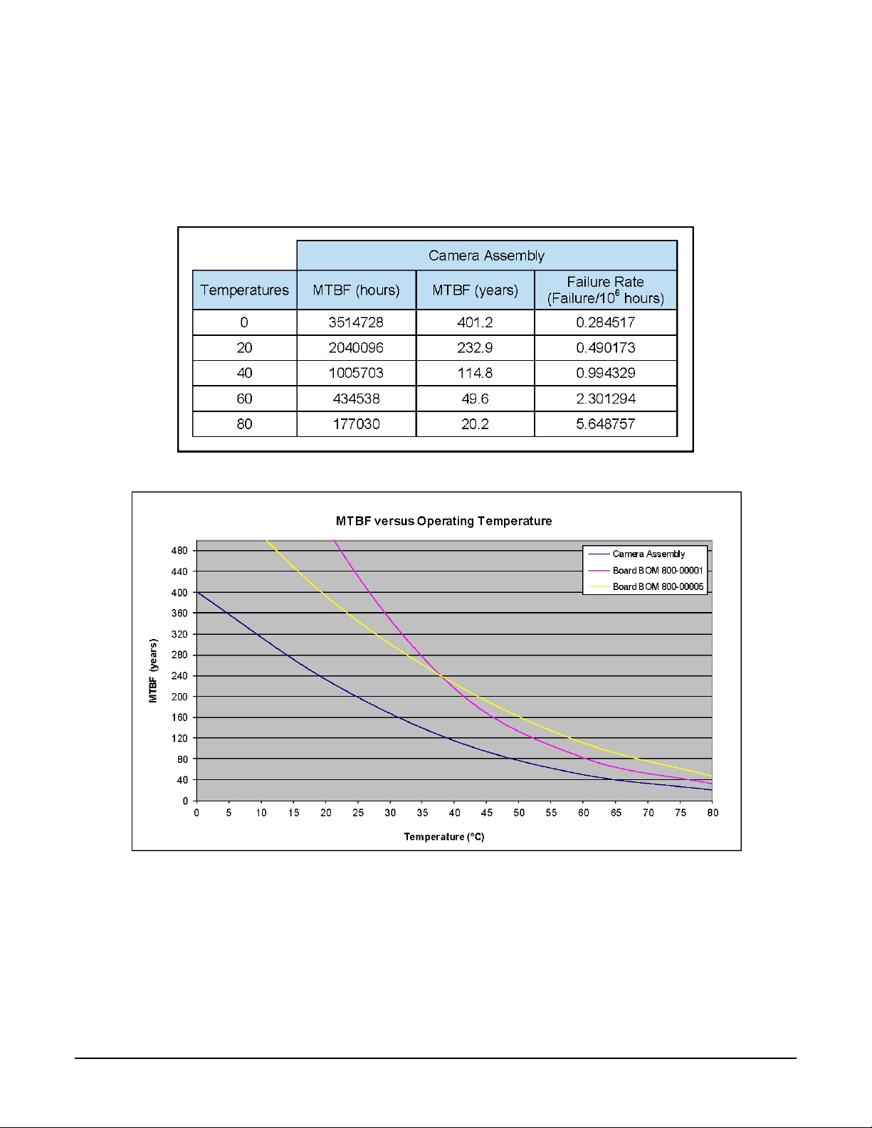
Mean Time Between Failure (MTBF)
The analysis was carried out for operating temperatures varying from 0 to 80ºC. The following
table presents the predicted MTBF and failure rate values.
22 • Genie Nano Series Overview Nano Series GigE Vision Camera
Model
Specifications: M/C1940 & M/C1920
Model specific specifications and response graphics for these Sony models are provided here. The
response curves describe the sensor, excluding lens and light source characteristics.
Supported Features
Camera Models
M1920
C1920
M1940
C1940
Minimum Frame Rate
(internal acquisition)
0.06 fps
0.06 fps
Maximum Internal Acquisition
Frame Rate
(entire resolution–1936x1216)*
38.8 fps
83.9 fps
Maximum Sustained Frame Rate
Output
(with TurboDrive)**
38.8 fps
(8-bit)
N/A
83.9 fps (8-bit)
N/A
Maximum Sustained Frame Rate
Output
(without TurboDrive)
38.8 fps (8-bit)
26.1 fps (12-bit)
26.1 fps (YUV422)
13 fps (RGB A)
52.2 fps (8-bit)
26.1 fps (10-bit)
26.1 fps (YUV422)
13 fps (RGB A)
Maximum Frame Rate Output
System dependent on the GigE network (based on typical 115 MBs of image data)
Pixel Data Formats
(Monochrome)
Mono 8-bit
Mono 12-bit
N/A
Mono 8
-bit
Mono
10-bit
N/A
Pixel Data Formats
(Bayer color)
N/A
Bayer 8-bit
Bayer 12-bit
N/A
Bayer 8-bit
Bayer 10-bit
Pixel Data Formats
(RGB Output Design)
N/A
Monochrome 8
-bit
YUV 422
RGB 24
-bits
RGBA 32-Bits
N/A
Monochrome 8
-bit
YUV 422
RGB 24
-bits
RGBA 32
-Bits
Trigger to Exposure
Minimum delay
2 line time (41 µs)
2 line time (19 µs)
Trigger to Exposure Start jitter
(best case)
Up to 1 line time
0 to 20.5 µs
Up to 1 line time
0 to 9.5 µs
Actual Sensor Exposure Time
Minimum ***
1 line time + 13.73 us = 34.23 µs
auto-adjusted to steps of 20.5 µs
1 line time + 13.73 us = 23.23 µs
auto-adjusted to steps of 9.5 µs
Horizontal Line Time
20.5 µs
9.5 µs
Min. Time from End of Exposur e
to Start of Next Exp osure
13 lines (266.5µs)
13 lines (123.5µs)
Readout Time
Horizontal Line Time (max) x (lines in full frame +20) — in μs
Internal Trigger to Start of
Exposure
2 to 3 line time
External Exposure Control
(1 line time + 13.73 us)
Gain Control
In-Sensor Gain: 48dB range
up to 24dB as analog gain in 0.1 dB steps (1x to 15x)
from 24dB to 48dB as digital gain in 0.1 dB steps (from 16x to 250x )
Additional Digital Gain: 4x
Black Offset Control
Yes (0 to 511 DN)
Binning
2x , 4x, Summing in FPGA ( Monochrome sensors only)
Auto-Brightness
Yes , with Auto-Exposure and AGC (Sensor Gain or FPGA Gain)
Note: Sensor Gain AGC only with Sony sensors
Multi-ROI Support
Yes — FPGA (firmware 1.01 or later)
Yes — In-Sensor
Pixel Size
5.86 µm x 5.86 µm

Nano Series GigE Vision Camera Genie Nano Series Overview • 23
Shutter
Full frame electronic
global shutter
function
Full Well charge
32 ke (max)
Output Dynamic Range
75.5 dB (12-bit), 68.3 dB (10
-bit)
Signal to Noise ratio
43.9 dB typical
DN Variation
50% saturation: < +/- 0.5%
Responsivity
see graphic:
* Entire Resolution includes Over-scan pixels:
• Active resolution is 1920x1200. The 8 + 8 additional pixels per line and 8 + 8 additional
vertical lines are available for preprocessing and/or camera mechanical alignment
operations in a system.
** Limited to the Genie Nano Architecture:
•
~250MB/sec Sustained into the TurboDrive Engine
•
Additional note: This transfer was
achieved using 1500 Byte Packet Size.
*** Actual Exposure Time:
• The actual internal minimum exposure may be different than what is programmed. Use the
feature “exposureTimeActual” from the Sensor Con t rol category to read back the actual
sensor exposure.
24 • Genie Nano Series Overview Nano Series GigE Vision Camera
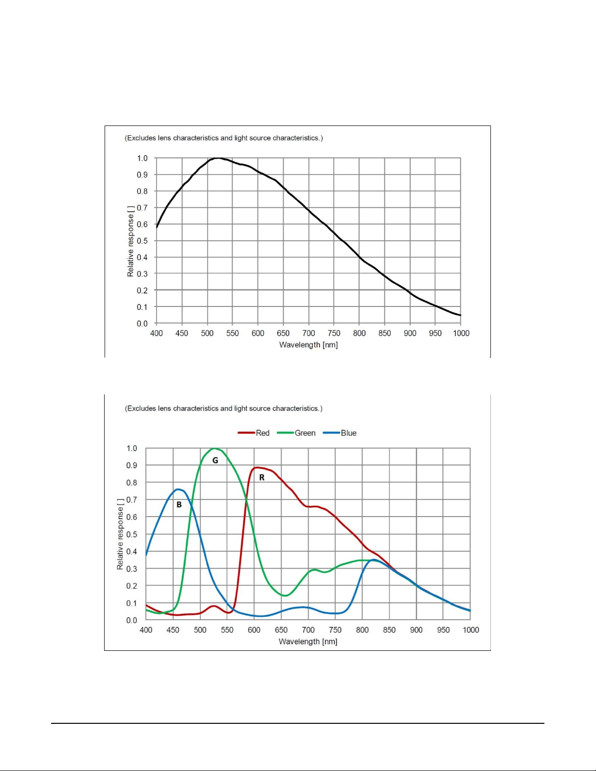
Spectral Response
Monochrome Models M194x & M192x, (Sony IMX174 & IMX249)
Measured Fill-Factor x Quantum Efficiency (FF x QE)
Color Models C194x & C192x, (Sony IMX174 & IMX249)
Measured Fill-Factor x Quantum Efficiency (FF x QE)
Nano Series GigE Vision Camera Genie Nano Series Overview • 25
Model
Specifications
: M
/C2020, M/C2050
Supported Features
Nano
-M/C2020
2048 x 1536
Nano-M/C2050
2048 x 1536
Sensor Firmware
Sony IMX265
Standard Design
Sony IMX252
Standard Design
Sony IMX252
Default
Firmware
High Sensitivity Design
Full Well charge † dependent on Firmware
Design Loaded
11ke (max)
11ke (max)
2.75ke (max)
Max. Internal Frame Rate
53 fps at
116 fps
143 fps
Maximum Sustained Frame Rate Output
(with TurboDrive)**
53 fps (8-bit Mono)
26 fps (12-bit Mono)
83 fps (monochrome camera only)
Maximum Sustained Frame Rate Output
(without TurboDrive)
36 fps (8-bit Mono)
18 fps (12-bit Mono)
18 fps (Yuv422 color)
9 fps (RGBA color)
Monochrome Camera: 24 fps (8-bit)
Color Camera: 24 fps (8-bit)
12 fps (Yuv422)
6 fps (RGBA)
Pixel Data Formats
Mono 8-bit / 12-bit
Mono 8-bit
Pixel Data Formats (Baye r o utput)
Bayer 8-Bit / 12-bit
Bayer 8-Bit
Pixel Data Formats (RGB output)
Monochrome 8
-bit
YUV 422
RGB 24
-bits
RGBA 32
-Bits
Monochrome 8
-bit
RGBA 32
-bit
RGB 24
-bit
Yuv422 16-
bit
Trigger to Exposure Minimum delay
(Synchronous Exposure Alignment)
2 line time (24 µs)
2 line time (10.8 µs)
2 line time (8.8 µs)
Trigger to Exposure Minimum delay
(Reset Exposure Alignment)
0 µs
0 µs
0 µs
Trigger to Exposure Start jitter (best case
with Synchronous Exposure Alignment)
Up to 1 line time
0 to 11.92 µs
Up to 1 line time
0 to 5.4 µs
Up to 1 line time
0 to 4.4 µs
Trigger to Exposure Start jitter
(Reset Exposure Alignment)
0 µs
0 µs
0 µs
Actual Exposure Time Minimum
(see “exposureTimeActual” in Sensor
Control)
1 line time+13.73µs
(25.65µs), auto step s of
11.9µs
1 line time+13.73µs
(19.13µs) auto steps
of 5.4µs
1 line time+13.73µs
(18.13µs) auto steps of
4.4µs
Horizontal Line Time
11.92 µs
5.4µs
4.4µs
Min. Time from End of Exposure to Start of
Next Exposure
8 lines – 13.73µs
(81.6 µs)
10 lines – 13.73µs
(40.4 µs)
10 lines – 13.73µs
(30.3 µs)
Readout Time
(H Line Time) x (lines in
frame +17) —
in μs
(H Line Time) x (lines in frame +23)
— in μs
Gain Control
In-sensor Analog Gain (1x to 1
5x), In
-sensor Digital Gain (1 to 16x)
Black offset control
Yes
Multi
-ROI Support
In
-FPGA
In
-Sensor
Pixel Size
3.45 µm x 3.45 µm
Shutter
Full frame electronic global shutter func ti o n
Output Dynamic Range (dB)
76.4
82.2
56.8
SNR (dB)
39.6
32.8
33.1
† Model M2050 also supports Standard Design Firmware which increases the Full Well charge to 11Ke but reduces the
maximum frame rate.
** Limited to the Genie Nano Architecture:
~250MB/sec Sustained into the TurboDrive Engine achieved using 1500 Byte Packet Size
26 • Genie Nano Series Overview Nano Series GigE Vision Camera
Model Specifications: M/C2420, M/C2450
Supported Features
Nano-M/C2420
2448 x 2048
Nano-M/C2450
2448 x 2048
Sensor Firmware
Sony IMX264
Standard Design
Sony IMX250
Standard Design
Sony IMX250
Default Firmware
High Sensitivity Design
Full Well charge † dependent on Firmware
Design Loaded
11ke (max)
11ke (max)
2.75ke (max)
Max. Internal Frame Rate
35 fps at
76 fps
93 fps
Maximum Sustained Frame Rate Output
(with TurboDrive)**
35 fps (8
-bit mono)
17.5 fps (12-bit mono)
53 fps (monochrome camera only)
Maximum Sustained Frame Rate Output
(without TurboDrive)
22.5 fps (8
-bit
Mono)
11 fps (12-bit Mono)
11 fps (Yuv422 color)
5.5 fps (RGBA color)
Monochrome Camera: 24 fps (8-bit)
Color Camera: 24 fps (8-bit)
12 fps (Yuv422)
6 fps (RGBA)
Pixel Data Formats
Mono 8-bit / 12-bit Mono 8-bit
Pixel Data Formats (Baye r o utput)
Bayer 8
-Bit / 12-bit
Bayer 8
-Bit
Pixel Data Formats
(RGB output)
Monochrome 8
-bit
YUV 422
RGB 24
-bits
RGBA 32
-Bits
Monochrome 8
-bit
RGBA 32-bit
RGB 24-
bit
Yuv422 16
-bit
Trigger to Exposure Minimum delay
(Synchronous Exposure Alignment
)
2 line time (28
µs)
2 line time (12.5
µs)
2 line tim
e (10.22
µs)
Trigger to Exposure Minimum delay
(Reset Exposure Alignment)
0 µs
0 µs
0 µs
Trigger to Exposure Start jitter (best case
with Synchronous Exposure Alignment)
Up to 1 line time
0 to 13.92 µs
Up to 1 line time
0 to 6.25 µs
Up to 1 line time
0 to 5.11 µs
Trigger to Exposure Start jitter
(Reset Exposure Alignment)
0 µs
0 µs
0 µs
Exposure Time Minimum
(see “exposureTimeActual” in Sensor
Control)
1 line time+13.73µs
(27.65µs) auto steps of
13.9µs
1 line time+13.73µs
(19.98µs) auto steps
of 6.25µs
1 line time+13.73µs
(18.83µs) auto steps of
5.11µs
Horizontal Line Time
13.92µs
6.25µs
5.11µs
Min. Time from End of Exposure to Start of
Next Exposure
8 lines – 13.73µs
(97.6 µs)
10 lines – 13.73µs
(48.8 µs)
10 lines – 13.73µs
(37.3 µs)
Readout Time
(H Line Time) x (lines in
frame +17) — in μs
(H Line Time) x (lines in frame +23) — in μs
Gain Control
In-sensor Analog Gain (1x to 16x), In-sensor Digital Gain (1 to 16x)
Black offset control
Yes
Multi-ROI Support
In-FPGA
In-Sensor
Pixel Size
3.45 µm x 3.45 µm
Shutter
Full frame electronic global shutter func ti o n
Output Dynamic Range (dB)
76.4
75.4
56.7
SNR (dB)
39.6
32.8
33.1
† Model M2450 also suppor ts Standard Design Firmware which increases the Full Well charge to 11Ke but red uces the
maximum frame rate.
** Limited to the Genie Nano Architecture:
~250MB/sec Sustained into the TurboDrive Engine achieved using 1500 Byte Packet Size
Nano Series GigE Vision Camera Genie Nano Series Overview • 27
Spectral Responses
The response curves describe the sensor, excluding lens and light source characteristics.
Models M2020, M2050, M2420, M2450
Models C2020, C2050, C2420, C2450
28 • Genie Nano Series Overview Nano Series GigE Vision Camera
Model
Specifications
: M/C4060, M/C
4040
Supported Features
M/C
-4060
4112 x 2176
(Sony IMX255)
M/C-4040
4112 x 3008 (Sony IMX253)
Sensor Firmware
Standard Design
High Sensitivity
Design (default)
Standard Design
High Sensitivity
Design (default)
Full Well charge dependent on
Firmware Design Loaded
11ke (max)
2.75ke (max)
11ke (max)
2.75ke (max)
Max. Internal Frame Rate
46 fps
56 fps
33 fps
41 fps
Maximum Sustained Frame Rate
Output (with TurboDrive)**
30 fps (monochrome camera only)
21 fps (monochrome camera only)
Maximum Sustained Frame Rate
Output (without TurboDrive)
Monochrome Camera: 14 fps (8-bit)
Color Camera:
14 fps (8-bit)
7 fps (Yuv422)
3.5 fps (RGBA)
Monochrome Camera: 9.7 fps (8
-bit)
Color Camera: 9.7 f ps (8-bit)
4.3 fps (Yuv422)
2.4 fps (RGBA)
Pixel Data Formats
Mono 8-bi
Mono 8
-bit
Pixel Data Formats
(Bayer output)
Bayer 8-Bit
Bayer 8-Bit
Pixel Data Formats
(RGB output)
Monochrome 8-bit
RGBA 32-bit
RGB 24-
bit
Yuv422 16-bit
Monochrome 8-bit
RGBA 32
-bit
RGB 24-bit
Yuv422 16-bit
Trigger to Exposure Minimum
delay (Synchronous Exposure)
2 line time (19.5µs)
2 line time
(15.8µs)
2 line time (19.5µs)
2 line time
(15.8µs)
Trigger to Exposure Minimum
delay (Reset Exposure )
0 µs
0 µs
0 µs
0 µs
Trigger to Exposure Start jitter
(Synchronous Exposure)
Up to 1 line time
0 to 9.72µs
Up to 1 line time
0 to 7.89µs
Up to 1 line time
0 to 9.72µs
Up to 1 line time
0 to 7.89µs
Trigger to Exposure Start jitter
(Reset Exposure)
0 µs
0 µs
0 µs
0 µs
Exposure Time Minimum
(see “exposureTimeActual” in
Sensor Control)
1 line time +
14.26µs (24µs)
auto adjusted
(9.72µs steps)
1 line time +
14.26µs (22µs)
auto adjusted
(7.89µs steps)
1 line time +
14.26µs (24µs)
auto adjusted
(9.72µs steps)
1 line time +
14.26µs (22µs)
auto adjusted
(7.89µs steps)
Horizontal Line Time (no binning)
(with in-sensor binning)
9.72µs
5.27µs
7.89µs
4.95µs
9.72µs
5.27µs
7.89µs
4.95µs
Min. Time from End of Exposure
to Start of Next Exp osure
16 lines – 14.26µs
(141.3µs)
16 lines – 14.26µs
(112µs)
16 lines – 14.26µs
(141.3µs)
16 lines – 14.26µs
(112µs)
Readout Time
(H Line Time) x (lines in frame +39) in μs
Gain Control
In-sensor Analog Gain (1x to 16x), In-sensor Digital Gain (1 to 16x)
Black offset control
Yes
Multi-ROI Support
In-Sensor (not available with in-sensor binning)
In-Sensor Binning (monochrome)
2x2 Only – provides increased frame r ate . (In-sensor single or multi-ROI is disabled).
Pixel Size
3.45 µm x 3.45 µm
Shutter
Full frame electronic global shutter func ti o n
Output Dynamic Range (dB)
76.46
56.43
76.46
56.43
SNR (dB)
39.60
33.01
39.60
33.01
** Limited to the Genie Nano Architecture:
~250MB/sec Sustained into the TurboD r ive Eng i ne achie ved using 1500 Byte Packet Size
 Loading...