


Relay PCA
P/N 04523
Addendum
to M100E, M200E and M400E
Operator Manuals
© TELEDYNE INSTRUMENTS ADVANCED POLLUTION INSTRUMENTATION
(T-API)
9480 CARROLL PARK DRIVE
SAN DIEGO, CA 92121-5201
USA
Toll-free Phone:
Phone:
Fax:
Email:
Website:
05118 Rev B3
DCN 5362
Copyright 2007 T-API Inc. 20 March 2009
800-324-5190
858-657-9800
858-657-9816
api-sales@teledyne.com
http://www.teledyne-api.com/

THIS PAGE INTENTIONALLY BLANK
Relay PCA 04523 Addendum to E-Series Operator Manuals
SAFETY MESSAGES
For general safety information please refer to your M100E/M200E/M400E operator’s manual.
CAUTION
Never disconnect electronic circuit boards, wiring harnesses or electronic
Printed circuit assemblies (PCAs) are sensitive to electro-static
discharges too small to be felt by the human nervous system. Failure
to use ESD protection when working with electronic assemblies will
subassemblies while the unit is under power.
void the instrument warranty.
See Chapter 12 of your M100E/M200E/M400E op erator’s manual for
more information on preventing ESD damage.
NOTE
Technical Assistance regarding the use and maintenance of the any Teledyne
Instruments product can be obtained by:
Contacting Teledyne Instruments’ Customer Service Department at 800-324-5 19 0
or
Via the internet at http://www.teledyne-api.com/inquiries.asp
05118 Rev B3 i

Addendum to E-Series Operator Manuals Relay PCA 04523
THIS PAGE INTENTIONALLY BLANK
ii 05118 Rev B3

Relay PCA 04523 Addendum to E-Series Operator Manuals
TABLE OF CONTENTS
1. INTRODUCTION........................................................................................................................... 1
1.1. What’s the Same.....................................................................................................................1
1.2. What’s Different......................................................................................................................2
1.3. Relay PCA Location and Layout..................................................................................................2
1.3.1. Version 045230200 ...........................................................................................................3
1.3.2. Version 045230100 ...........................................................................................................3
2. OPERATION AND CONFIGURATION.............................................................................................. 5
2.1. Power Distribution...................................................................................................................5
2.1.1. AC Power Configuration .....................................................................................................5
2.1.1.1. AC configuration – Internal Pump (JP7)..........................................................................7
2.1.1.2. AC Configuration – Standard Heaters (JP2).....................................................................8
2.1.1.3. AC Configuration –Heaters for Option Packages (JP6).......................................................9
2.2. Valve Control..........................................................................................................................9
2.3. Status LEDs & Watch Dog Circuitry ..........................................................................................10
2.3.1. Watchdog Indicator (D1)..................................................................................................10
2.4. Heater Control Loop...............................................................................................................11
2.4.1. Thermocouple Inputs and Configuration Jumper (JP5) ..........................................................12
2.5. DC Power Supply Test Points...................................................................................................14
3. TROUBLE SHOOTING AND REPAIR..............................................................................................15
3.1. Removing / Replacing the Relay PCA from the Instrument...........................................................15
4. SCHEMATICS AND SPARE PARTS FOR RELAY PCA P/N 04523.....................................................16
LIST OF FIGURES
Figure 1-1: Relay PCA Layout (P/N04523)..........................................................................2
Figure 1-2: Relay PCA P/N 045230200 with AC Relay Retainer In Place..................................3
Figure 1-3: Relay PCA P/N 045230100 with Safety Shield In Place.........................................3
Figure 2-1: Power Distribution Block Diagram.....................................................................5
Figure 2-2: Location of AC power Configuration Jumpers......................................................6
Figure 2-3: Pump AC Power Jumpers (JP7) ........................................................................7
Figure 2-4: Typical Set Up of AC Heater Jumper Set (JP2)....................................................8
Figure 2-5: Typical Set Up of AC Heater Jumper Set (JP2)....................................................9
Figure 2-6: Status LED Locations – Relay PCA 04523.........................................................10
Figure 2-7: Heater Control Loop Block Diagram. ............................................................... 11
Figure 2-8: Thermocouple Configuration Jumper (JP5) Pin-Outs.......................................... 13
Figure 3-1: Relay PCA 04523 Mounting Screw Locations .................................................... 15
LIST OF TABLES
Table 1-1: List of Analyzers Using New Relay PCA P/N04523 ................................................1
Table 2-1: AC Power Configuration for Internal Pumps (JP7).................................................7
Table 2-2: Power Configuration for Standard AC Heaters (JP2) .............................................8
Table 2-3: Power Configuration for Optional AC Heaters (JP6)...............................................9
Table 2-4: Thermocouple Configuration Jumper (JP5) Pin-Outs ........................................... 12
Table 2-5: Typical Thermocouple Settings for M100E/M200E series analyzers ....................... 13
Table 2-5: DC Power Test Point and Wiring Color Code ...................................................... 14
Table 2-6: DC Power Supply Acceptable Levels................................................................. 14
Table 4-1: List of Spare Parts......................................................................................... 16
Table 4-2: List of Included Electronic Schematics.............................................................. 16
05118 Rev B3 i

Addendum to E-Series Operator Manuals Relay PCA 04523
THIS PAGE INTENTIONALLY BLANK
ii 05118 Rev B3
Relay PCA 04523 Addendum to E-Series Operator Manuals
1. INTRODUCTION
This addendum documents a recent upgrade to the relay card installed in some of the M100E,
M200E and M400E series analyzers. Specifically, a new relay PCA design, P/N 04523 replaces P/N
03955 and all of its versions in the following instruments.
It also corrects several errors related to the function of the relay PCA.
Table 1-1: List of Analyzers Using New Relay PCA P/N04523
1
PRODUCT FAMILY MODEL
M100E
UV Fluorescence
Chemiluminescence
UV Absorption
Analyzers
1
See Sections 1.3.1 and 1.3.2
M100EH
M101E
M102E
M200E
M200EH
M200EM
M201E
M400E
RELAY PCA VERSION
045230100
045230200
For those instruments, the information included in this addendum supersedes the information
related to the relay PCA that appears in the chapters on Theory of Operation
and Troubleshooting
& Repair of your M100E/M200E/M400E operator’s manual’s.
Because the operator’s manual for each model family of the E-Series instruments is slightly
different there is no direct correspondence between the sections and chapters of this addendum
and those of the manual.
1.1. What’s the Same
In most respects the electronic operation of the Relay PCA 04523 is the same as Relay PCA
03955.
Both are used by the CPU to operate various AC and DC heaters that control the
temperature of key components of the E-Series analyzers to such as sensor modules,
reaction cells and converters as well as certain optional components such as IZS
permeation tubes.
In both cases a set of configuration jumpers located on the relay card is used to configure
the heaters for 110 VAC, 60 Hz vs. 230 VAC, 50 Hz operation.
Both Relay cards, based on commands from the CPU received over the
energize/de-energize the various solenoid valves used to control the sample gas path of
the analyzers (e.g. reference/measure valves; zero-span-cal valve options; IZS options;
etc.)
Both distribute the AC and DC power to the various electrically powered components and
assemblies for the instrument.
Both include a special watchdog circuit watches that will automatically shut of all valves as
well as turn off the UV Source(s) and all heaters should either the CPU cease issuing
commands or the I
2C
bus fail. In both cases the sample pump will continue to run.
I2C bus,
05118 Rev B3 1

Addendum to E-Series Operator Manuals Relay PCA 04523
V
A
V
1.2. What’s Different
The major differences between the Relay PCA 04523 and Relay PCA 03955 are:
On instruments with internal pumps, the pump is now configured for use with 110 VAC, 60
Hz vs. 220 VAC, 50 Hz operation by a set of configuration jumpers on the Relay PCA.
Previously a set of inline connectors and wiring harnesses performed this function.
The configurability of the two thermocouple inputs has been expanded to allow for both
grounded and ungrounded thermocouples
A retainer plate has been added to the 045230200 version to keep the solid state AC
power relays securely inserted in their sockets.
Because the board has been physically changes, locations of components such as jumper
blocks, connectors and status LED’s have changed.
1.3. Relay PCA Location and Layout
Generally the relay PCA is located in the right-rear quadrant of the analyzer and is mounted
vertically on the back side of the same bracket as the instrument’s DC power supplies, however
the exact location of the relay PCA may differ from model to model. Please check the Getting
Started chapter of your M100E/M200E/M400E operator’s manual.
Thermocouple
Configuration
Configuration
Pump Power
Power Output
Thermocouple
Signal Output
(JP5)
Jumpers
(J15)
TC1 Input
(J16)
TC2 Input
(JP7)
Pump AC
Jumper
Output
AC Po wer
IN
AC Heater
Solid State AC
Power Relays
(Not Present on
P/N 45230100)
Status LED’s
(D2 through D16)
AC Configuration Jumpers
for Optional IZS Valve
(JP2)
Heaters & 0
Sensors
2
Watchdog
Status LED
(D1)
(JP6)
Main AC Heater
Configuration Jumpers
C Power Outp ut for
Optional IZS Valve
Heaters & 0
sensors
2
DC Power Supply
Test Points
I2C
Connector
Power
Connection
for DC
Heaters
Shutter Control
Connector
(M100E Series
Only)
alve Control
Drivers
alve Option
Control
Connector
DC Power
Distribution
Connectors
Figure 1-1: Relay PCA Layout (P/N04523)
2 05118 Rev B3

Relay PCA 04523 Addendum to E-Series Operator Manuals
A
There are two versions of the new relay card. Table 1-1 above cross references the PCA version
with the various E-series analyzer models.
1.3.1. Version 045230200
This is the most commonly used version of the Relay PCA. It includes a bank of solid state AC
relays. This version is installed in analyzers where components such as AC powered heaters must
be turned ON & OFF. A retainer plate is installed over the relay to keep them securely seated in
their sockets.
Retainer
Mounting
Screws
C Relay
Retainer Plate
Figure 1-2: Relay PCA P/N 045230200 with AC Relay Retainer In Place
1.3.2. Version 045230100
This is the base version of the Relay PCA. It does not include the AC relays and is used in
instruments where there are no AC powered components requiring control. A plastic insulating
safety shield covers the empty AC Relay sockets (See Figure 1-3)
CAUTION
Never remove this safety shield while the instrument is plugged in and
turned on. The contacts of the AC relay sockets beneath the shield carr y
high AC voltages even when no relays are present
AC Relay
Safety Shield
Figure 1-3: Relay PCA P/N 045230100 with Safety Shield In Place
05118 Rev B3 3

Addendum to E-Series Operator Manuals Relay PCA 04523
USER NOTES:
4 05118 Rev B3

Relay PCA 04523 Addendum to E-Series Operator Manuals
2. OPERATION AND CONFIGURATION
2.1. Power Distribution
SENSOR SUITES
ANALOG
SENSORS
(e.g. UV sen so rs,
Temp Sensors,
Flow Sensors,
IR, Sensors,
PMT HVPS, etc.)
PUMP
AC HEATERS
AC HEATERS for
OPTIONAL IZS
PERMEATION TUBE
AND O2 SENSOR
UV Lamp
P/S
Sensor Control
& I/O Logic
Pre-A mplifiers
& Amplifiers
Configuration
Jumpers
Configuration
Jumpers
Configuration
Jumpers
RELAY PCA
LOGIC DEVICES
(e.g. C P U , I2C bus,
Keyboard, Display,
MotherBoard, etc.)
Solenoid
Drivers
PS 1
+5 VDC
±15 VDC
PS 2
(+12 VDC)
KEY
AC POWER
DC POWER
ON / OFF
SWITCH
AC
POWER IN
UV SHUTTER
SOLENOID
(M100E Series Only)
MODEL SPECIFIC
VALVES
(e.g. M/R V a lves ,
Auto-zero valves,
etc.)
OPTIONAL
VALVES
(e.g. Sam p le/C al,
Zero/Spans, etc.)
COOLING
FAN(S)
Figure 2-1: Power Distribution Block Diagram
2.1.1. AC Power Configuration
The E-Series digital electronic systems will operate wit h any of the specified power regimes. As
long as instrument is connected to 100-120 VAC or 220-240 VAC at either 50 or 60 Hz it will turn
on and after about 30 seconds show a front panel display. Internally, the status LEDs located on
the Relay PCA, Motherboard and CPU should turn on as soon as the power is supplied.
On the other hand, some of the analyzer’s non-digital components, such as the pump and the
various AC powered heaters must be properly configured for the type of power being supplied to
the instrument. Figure 2-3 shows the location of the various sets of AC Configuration jumpers.
05118 Rev B3 5

Addendum to E-Series Operator Manuals Relay PCA 04523
JP6
IZS Permeation
Tube Heater and O
Sensor Connection.
(optional)
2
JP7
Pump
Configuration
Figure 2-2: Location of AC power Configuration Jumpers
There are several changes between the Relay PCA 04523 and previous version regarding AC
power configuration and distribution.
Main AC Heater
Configuration
JP2
Previously, in analyzer models with intern al pumps, the AC power for the pump came
directly from the instrument back panel. The 04523 version handles all AC and DC power
distribution including power to the pump.
Prior to this change, configuring the pump for compatibility with various line voltages and
frequencies was done with a set of hard-wired, in-line connections. The Relay PCA
04523, now includes a set of jumpers that perform this function. This change increase
reliability and simplifies troubleshooting and repair operation s .
The Relay PCA 04523, includes a set of jumpers that connect AC power to heaters
included in several optional items, such as the IZS valve option and the O
sensor option
2
available on the M100E, M200E and M400E series instruments. In earlier versions of the
relay PCA this was also handled by in-line connections.
6 05118 Rev B3

Relay PCA 04523 Addendum to E-Series Operator Manuals
2.1.1.1. AC configuration – Internal Pump (JP7)
AC power configuration for internal pumps is set using Jumper set JP7 (see Figure 1-1 for the
location of JP7).
Table 2-1: AC Power Configuration for Internal Pumps (JP 7)
LINE
POWER
110VAC
115 VAC
220VAC
240 VAC
1
A jumper between pins 5 and 10 may be present on the jumper plug assembly, but is only functional on
the M300E and has no function on the Models M100E, M200E or M400E.
LINE
FREQUENCY
60 HZ WHITE
50 HZ
60 HZ BROWN
50 HZ
110 VAC /115 VAC
1
1
JUMPER
COLOR
BLACK
BLUE
FUNCTION
Connects pump pin 3 to 110 / 115 VAC power line 2 to 7
Connects pump pin 3 to 110 / 115 VAC power line 3 to 8
Connects pump pins 2 & 4 to Neutral 4 to 9
Connects pump pin 3 to 110 / 115 VAC power line 2 to 7
Connects pump pin 3 to 110 / 115 VAC power line 3 to 8
Connects pump pins 2 & 4 to Neutral 4 to 9
Connects pump pins 3 and 4 together 1 to 6
Connects pump pin 1 to 220 / 240VAC power line 3 to 8
Connects pump pins 3 and 4 together 1 to 6
Connects pump pin 1 to 220 / 240VAC power line 3 to 8
220 VAC /240 VAC
JUMPER
BETWEEN
PINS
1
2
3
4
5
Present on 50 Hz version of jumper set,
Figure 2-3: Pump AC Power Jumpers (JP7)
05118 Rev B3 7
6
7
8
9
10
and functional for M300E but not
Models M100E, M200E & M400E
1
2
3
4
5
6
7
8
9
10

Addendum to E-Series Operator Manuals Relay PCA 04523
2.1.1.2. AC Configuration – Standard Heaters (JP2)
Power configuration for the AC the standard heaters is set using Jumper set JP2 (see Figure 1-1
for the location of JP2).
Table 2-2: Power Configuration for Standard AC Heaters (JP2)
LINE VOLTAGE
110 VAC / 115 VAC
50Hz & 60 Hz
220 VAC / 240 VAC
50Hz & 60 Hz
1
No AC Heaters are used in the M400E series analyzers.
JUMPER
COLOR
WHITE
BLUE
HEATER(S)
Reaction Cell / Sample
Chamber Heaters
Mini Hi-Con
Converter
Moly Converter
By Pas Manifold
Reaction Cell / Sample
Chamber Heaters
Hi Concentration
Converter
Moly Converter
By Pas Manifold
MODEL’S
USED ON
2
M100E’s &
M200E’s
M200EH
M101E and
M200E’s
M200#M &
M200EH
M100E’s &
M200E’s
M100EH
M101E and
M200E’s
M200#M &
M200EH
1
JUMPER
BETWEEN
PINS
1 to 8
2 to 7
3 to 10
4 to 9
3 to 10
4 to 9
5 to 12
6 to 11
1 to 7
3 to 9
3 to 9
5 to 11
FUNCTION
Common
Neutral to Load
Common
Neutral to Load
Common
Neutral to Load
Common
Neutral to Load
Load
Load
Load
Load
Reaction Cell or
Sample Chamber
Heaters
Mini Hi-Con or
Moly Converter
Heaters
200EM/EH
By Pass Manifold
Heater
1
2
3
4
5
6
110 VAC /115 VAC
7
8
9
10
11
12
1
2
3
4
5
6
7
8
9
10
11
12
220 VAC / 240 VAC
Reaction Cell or
Sample Chamber
Heaters
Mini Hi-Con or
Moly Converter
Heaters
200EM/EH
By Pass Manifold
Heater
Figure 2-4: Typical Set Up of AC Heater Jumper Set (JP2)
8 05118 Rev B3

Relay PCA 04523 Addendum to E-Series Operator Manuals
2.1.1.3. AC Configuration –Heaters for Option Packages (JP6)
Both the IZS valve option or an O2 sensor options include AC heaters that maintain an optimum
operating temperature for key components of those options. Jumper set JP6 is used to connect
the heaters associated with those options to AC power. Since these heaters work with either
110/155 VAC or 220/240 VAC, there is only one jumper configuration.
Table 2-3: Power Configuration for Optional AC Heaters (JP6)
JUMPER
COLOR
RED
HEATER(S)
IZS Permeation Tube
Heater
O2 Sensor Heater
MODEL’S
USED ON
M100E’s,
M200E’s &
M400E
M100E’s &
M200E’s
1
JUMPER
BETWEEN
PINS
1 to 8
2 to 7
3 to 10
4 to 9
FUNCTION
Common
Neutral to Load
Common
Neutral to Load
IZS
Permeation Tube
Heater
10 9
12 11
8 7
Sensor
O
2
Heater
6 5
4 3 2 1
Figure 2-5: Typical Set Up of AC Heater Jumper Set (JP2)
2.2. Valve Control
Other than the location of the connectors and control chips on the PCA (see Figure 1-1 above),
there have been no significant changes to the method by which the E-Series instruments’ various
valves and valve options are controlled.
05118 Rev B3 9

Addendum to E-Series Operator Manuals Relay PCA 04523
2.3. Status LEDs & Watch Dog Circuitry
Like the previous version, the status LED’s on the Relay PCA 04523 includes thirteen LEDs that
indicate the status of the analyzer’s heaters, valves and other general operating conditions. Since
the functions represented by these LED differs from model to model, check your
M100E/M200E/M400E operator’s manual for their exact assignments (this can normally be found
in the section on Electronic Theory of Operation).
While the functional assignments for the LED’s of each model have remained unchanged their
location on the PCA is different. See Figure 2-3 of this addendum for the new locations.
2.3.1. Watchdog Indicator (D1)
The most important of the status LED’s on the relay board is the red I1C Bus watch-dog LED. It is
controlled directly analyzer’s CPU over the I
status of D1. Should this LED ever stay ON or OFF for 30 seconds, indicating that the CPU or I
2
C bus. Special circuitry on the relay PCA watches the
2
C
bus has stopped functioning, this Watchdog Circuit automatically shuts all valves and turn off all
heaters and lamps.
D4 (Yellow)
D3 (Yellow)
D2 (Yellow)
D5(Yellow)
D6 (Yellow)
D11 (Green)
D12 (Green)
D13 (Green)
D14 (Green)
D15 (Green)
D16 (Green)
D7 (Green)
D8 (Green)
D9 (Green)
D10 (Green)
D1 (RED)
Watchdog
Indicator
Figure 2-6: Status LED Locations – Relay PCA 04523
10 05118 Rev B3

Relay PCA 04523 Addendum to E-Series Operator Manuals
2.4. Heater Control Loop
Thermistor(s) – Low T em perature Sensing:
(e.g. Sample Chamber and Reaction
Cell temperatures)
Themocouple(s)
(High Temperature Sensing;
e.g. Moly and HiCon
Converter temperatures)
RELAY PCA
THERMOCOUPLE
CONFIGURATION
JUMPER
(JP5)
DC
Control
Logic
Preamplifiers
and Signal
Conditioning
Cold Junc tion
Compensation
Solid State
AC Relays
MOTHER BOARD
A/D
Converter
(V/F)
CPU
AC HEATERSDC HEATERS
Figure 2-7: Heater Control Loop Block Diagram.
While the role of the heater control lop for the E-Series analyzers is basically unchanged from the
previous version (see Figure 2-4) the configurability of the Thermocouple inputs has been
enhanced. Previously, the two T/C inputs could be configured for either type-T or type-K
thermocouples. The 04523 relay PCA adds the following.
Both T/C’s can now be configured as either grounded or ungrounded thermocouples.
Standard configuration of the both type of thermocouples is 10 mV/°C. In order to
accommodate the M200EH’s Mini High-Con converter option, a type-K; 5mV/°C output
configuration has been added.
05118 Rev B3 11

Addendum to E-Series Operator Manuals Relay PCA 04523
2.4.1. Thermocouple Inputs and Configuration Jumper (JP5)
Although the 04523 relay PCA supports two thermocouple inputs, the current M100E/M200E
series analyzers only utilize one and the M400E series analyzers none. By default, this single
thermocouple input is plugged into the TC1 input (J15). TC2 (J 16) is currently not used. See
Figure 1-1 for location of J15 and J16
Table 2-4: Thermocouple Configuration Jumper (JP5) Pin-Outs
TC INPUT JUMPER PAIR DESCRIPTION FUNCTION
Selects preamp gain factor for J or K TC
- IN = J TC gain factor
- OUT = K TC gain factor
Selects preamp gain factor for J or K TC
- IN = 5 mV / °C
- OUT = 10 mV / °C
When present, sets Cold Junction
Compensation for J type Thermocouple
When present, sets Cold Junction
Compensation for K type Thermocouple
Selects between Isolated and grounded
TC
- IN =
- OUT = Grounded TC
Isolate TC
TC1
1 – 11
2 – 12
Gain Selector
Output Scale Selector
3 – 13 Type J Compensation
4 – 14 Type K Compensation
5 – 15 Termination Selector
TC2
6 – 16
7 – 17
Gain Selector
Output Scale Selector
8 – 18 Type J Compensation
9 – 19 Type K Compensation
10 – 20 Termination Selector
Same as Pins 1 – 11 above.
Same as Pins 2 – 12 above.
Same as Pins 3 – 13 above.
Same as Pins 4 – 14 above.
Same as Pins 5 – 15 above.
12 05118 Rev B3

Relay PCA 04523 Addendum to E-Series Operator Manuals
Output Scale Selector 2 – 12
Type J Compensation 3 – 13
Type J Compensation 4 – 14
Termination Selector 5 – 15
Input Gain Selector 1 – 11
Input Gain Selector 6 – 16
Output Scale Selector 7 – 17
Type J Compensation 8 – 18
Termination Selector 10 – 20
Type J Compensation 9 – 19
TC1 TC2
Figure 2-8: Thermocouple Configuration Jumper (JP5) Pin-Outs
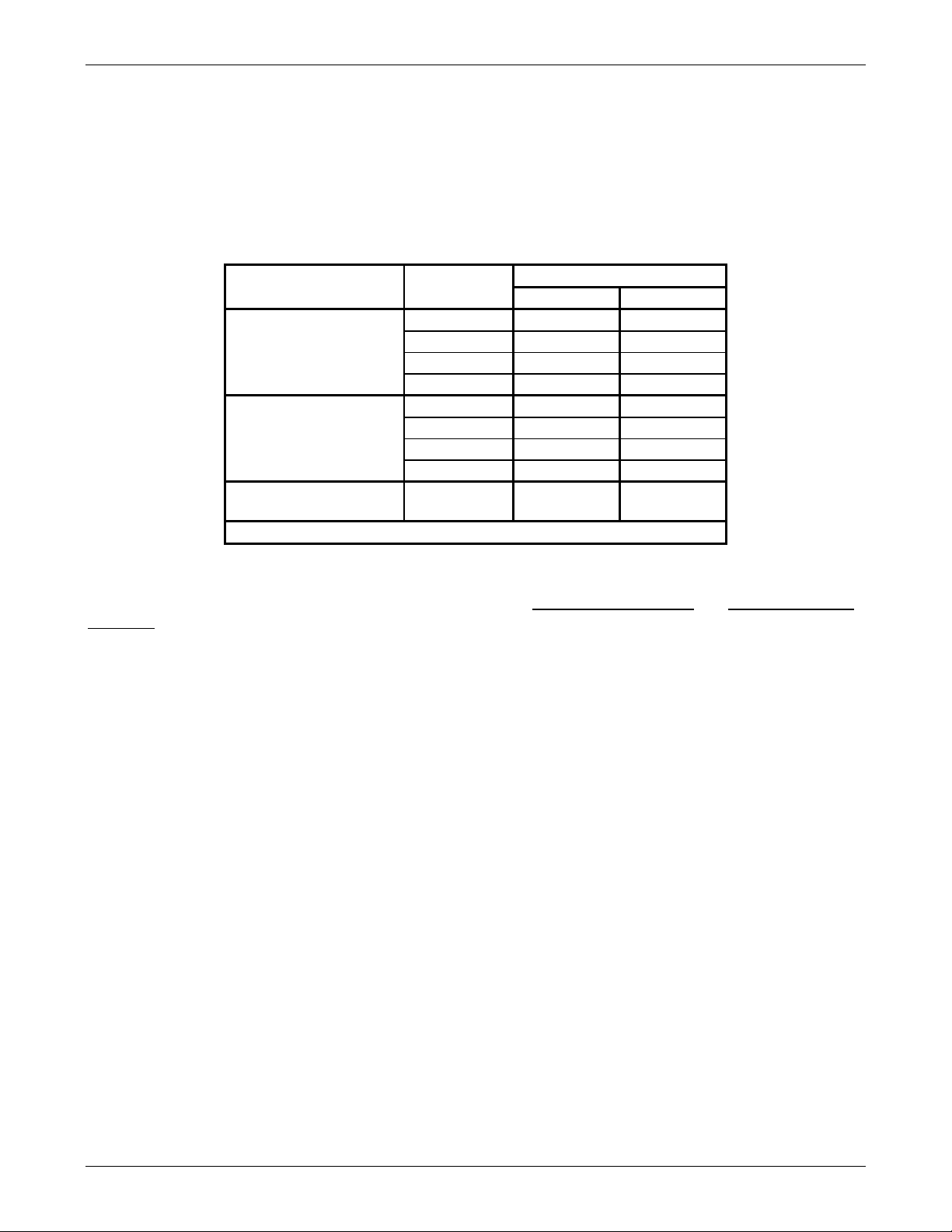
Table 2-5: Typical Thermocouple Settings for M100E/M200E series analyzers
TC
TYPE
TERMINATION
TYPE
OUTPUT
SCALE
TYPE
JUMPER
BETWEE
N PINS
USED ON
INPUT TC1 (J15)
K
GROUNDED 5mV / °C
2 – 12
4 – 14
M100EH with Mini HiCon Converter BROWN
2 – 12
K
ISOLATED 5mV / °C
4 – 14
M100EH with Mini HiCon Converter GREY
5 – 15
K
ISOLATED 10mV / °C
4 – 14
5 – 15
M100E/M200E with Moly Converter PURPLE
1 – 11
J
ISOLATED 10mV / °C
3 – 13
M100E/M200E with Moly Converter
5 – 15
JUMPER
COLOR
RED
J
05118 Rev B3 13
GROUNDED 10mV / °C
1 – 11
3 – 13
M100E/M200E with Moly Converter GREEN

Addendum to E-Series Operator Manuals Relay PCA 04523
2.5. DC Power Supply Test Points
The tables defining the names and functions of the DC power test point that appear in Chapter 11
of some revisions of the M100E/M200E/M400E operator’s manual are incorrect. The following
tables show the correct information.
Table 2-5: DC Power Test Point and Wiring Color Code
NAME TEST POINT# COLOR DEFINITION
DGND
+5V
AGND
+15V
-15V
+12R
+12V
1
2
3
4
5
6
7
Black Digital ground
Red
Green Analog ground
Blue
Yellow
Purple 12 V return (ground) line
Orange
Table 2-6: DC Power Supply Acceptable Levels
CHECK RELAY BOARD TEST
POWER
SUPPLY
PS1 +5 DGND 1 +5 2 +4.80 +5.25
PS1 +15 AGND 3 +15 4 +13.5 +16.0
PS1 -15 AGND 3 -15V 5 -14.0 -16.0
PS1 AGND AGND 3 DGND 1 -0.05 +0.05
PS1 Chassis DGND 1 Chassis N/A -0.05 +0.05
PS2 +12 +12V Ret 6 +12V 7 +11.8 +12.5
PS2 DGND +12V Ret 6 DGND 1 -0.05 +0.05
VOLTAG
E
FROM
Test Point
NAME # NAME #
POINTS
TO
Test Point
MIN V MAX V
As on the previous version of the relay card, the test points are located at the top, right-hand
corner of the PCA (see Figure 1-1)
USER NOTES:
14 05118 Rev B3

Relay PCA 04523 Addendum to E-Series Operator Manuals
A
3. TROUBLE SHOOTING AND REPAIR
General Trouble shooting hints for the relay PCA are the same as described for the previous
versions for the PCA. See Chapter 11 of your M100E/M200E/M400E operator’s manual for more
information.
3.1. Removing / Replacing the Relay PCA from the Instrument
The Relay retainer plate installed on the 045230200 PCA (version with AC relays) covers the lower
right mounting screw of the relay PCA. Therefore, when removing the relay PCA, the retainer
plate must be removed first.
Figure 3-1: Relay PCA 04523 Mounting Screw Locations
USER NOTES:
Mounting
Screws
C Relay Retain Occludes
Mounting Screw on
P/N 045230200
05118 Rev B3 15

Addendum to E-Series Operator Manuals Relay PCA 04523
4. SCHEMATICS AND SPARE PARTS FOR RELAY
PCA P/N 04523
Table 4-1: List of Spare Parts
DOCUMENT # DOCUMENT TITLE
RL0000015 Relay, DPDT, AC, Solid State, E-Series
041520500 Module, Relay PCA & Power Supply
Table 4-2: List of Included Electronic Schematics
DOCUMENT # DOCUMENT TITLE
04524 PCA, 04523, M100E, M200E, M400E Relay PCB
USER NOTES:
16 05118 Rev B3
 Loading...