

Teledyne Linea ML ML-FC-08K10T, Linea ML ML-HC-16K10T User Manual
Linea ML Color Cameras
ML-FC-08K10T and ML-HC-16K10T
sensors |
cameras
| frame grabbers | processors | software | vision solutions
03-032-20256-01
www.teledynedalsa.com

Notice
© 2019 Teledyne Digital Imaging, Inc.
All information provided in this manual is believed to be accurate and reliable. No
responsibility is assumed by Teledyne Digital Imaging for its use. Teledyne Digital Imaging
reserves the right to make changes to this information without notice. Reproduction of this
manual in whole or in part, by any means, is prohibited without prior permission having
been obtained from Teledyne Digital Imaging.
Microsoft and Windows are registered trademarks of Microsoft Corporation in the United
States and other countries. Windows, Windows 7, Windows 8 are trademarks of Microsoft
Corporation.
All other trademarks or intellectual property mentioned herein belong to their respective
owners.
Document Date: 7 June 2019
Document Number: 03-032-20256-01
About Teledyne DALSA
Teledyne DALSA, a business unit of Teledyne Digital Imaging, Inc., is an international highperformance semiconductor and Electronics Company that designs, develops, manufactures,
and markets digital imaging products and solutions, in addition to providing wafer foundry
services.
Teledyne DALSA offers the widest range of machine vision components in the world. From
industry-leading image sensors through powerful and sophisticated cameras, frame
grabbers, vision processors and software to easy-to-use vision appliances and custom vision
modules.
Contact Teledyne DALSA
Teledyne DALSA is headquartered in Waterloo, Ontario, Canada. We have sales offices in
the USA, Europe and Asia, plus a worldwide network of representatives and agents to serve
you efficiently. Contact information for sales and support inquiries, plus links to maps and
directions to our offices, can be found here:
Sales Offices: http://www.teledynedalsa.com/corp/contact/offices/
Technical Support: http://www.teledynedalsa.com/imaging/support/
***THIS IS AN UNCONTROLLED COPY OF A CONTROLLED DOCUMENT***
The information contained herein is proprietary to Teledyne DALSA and is to be
used solely for the purpose for which it is supplied.
It shall not be disclosed in whole or in part, to any other party, without the
express permission in writing by Teledyne DALSA

The Linea ML Color Camera Contents 1
Contents
THE LINEA ML COLOR CAMERA 4
DESCRIPTION 4
CAMERA HIGHLIGHTS 5
Key Features 5
Programmability 5
Applications 5
PART NUMBERS AND SOFTWARE REQUIREMENTS 6
PERFORMANCE SPECIFICATIONS 6
Flash Memory Size 8
Certification & Compliance 8
CAMERA PIXEL ARRANGEMENT 9
CAMERA PROCESSING CHAIN 9
SUPPORTED INDUSTRY STANDARDS 10
GenICam™ 10
Camera Link HS 10
Data Cables 11
RESPONSIVITY 12
MECHANICAL DRAWINGS 13
PRECAUTIONS 15
Electrostatic Discharge and the CMOS Sensor 15
INSTALL & CONFIGURE FRAME GRABBER & SOFTWARE 15
Using Sapera CamExpert 15
CamExpert Panes 17
SETTING UP FOR IMAGING 19
Powering the Camera 19
Power and GPIO Connections 20
Establishing Camera Communications 22
Selecting the Data Format 22
Establishing Data Integrity 22
CAMERA PERFORMANCE AND FEATURES 24
SYNCHRONIZING TO OBJECT MOTION 24
Triggering the camera 24
Measuring Line Rate (Trigger) 24
Maximum Line Rate 25
Minimum Line Rate 25
Scan Direction 25
Camera Orientation 27
Spatial Correction 28
Parallax Correction: Using the Camera at Non-Perpendicular Angles to
the Object 30
ESTABLISHING THE DESIRED RESPONSE 32
Exposure Mode 32
Line Rate Jitter 32
Exposure Control 32
Exposure Time Selector 33
Measuring Exposure Time 33

2 Contents The Linea ML Color Camera
Adjusting Responsivity 33
Image Response Uniformity 34
White Balancing 34
Adjusting Flat Field Calibration Coefficients 36
Saving & Loading a PRNU Set Only 36
Setting Custom Flat Field Coefficients 36
Flat Field Calibration Filter 36
Flat Field Calibration Region of Interest 37
IMAGE FILTERS 37
Kernels 37
Image Filter Contrast Ratio 38
BINNING 38
Using Area of Interest (AOIs) 39
Steps to Setup Area of Interest 39
The Rules for Setting Areas of Interest 39
CUSTOMIZED LINEARITY RESPONSE (LUT) 40
How to Generate LUT with CamExpert 40
ADJUSTING RESPONSIVITY AND CONTRAST ENHANCEMENT 42
CHANGING OUTPUT CONFIGURATION 43
Pixel Format 43
Using Two CLHS Cables 43
SAVING & RESTORING CAMERA SETUP CONFIGURATIONS 44
Active Settings for Current Operation 45
User Setting 45
Factory Settings 45
Default Setting 45
APPENDIX A: GENICAM COMMANDS 46
Camera Information Category 47
Camera Information Feature Descriptions 47
Built-In Self-Test Codes (BIST) 49
Camera Power-Up Configuration Selection Dialog 49
Camera Power-up Configuration 49
User Set Configuration Management 49
Camera Control Category 49
Camera Control Feature Descriptions 50
Digital I/O Control Feature Descriptions 52
Flat Field Category 55
Flat Field Control Feature Description 55
Image Format Control Category 57
Image Format Control Feature Description 58
Transport Layer Control Category 60
Transport Layer Feature Descriptions 60
Acquisition and Transfer Control Category 61
Acquisition and Transfer Control Feature Descriptions 62
File Access Control Category 62
File Access Control Feature Descriptions 62
File Access via the CamExpert Tool 64
CLHS File Transfer Protocol 64
Download a List of Camera Parameters 66
APPENDIX B: TROUBLE SHOOTING GUIDE 67
DIAGNOSTIC TOOLS 67

The Linea ML Color Camera Contents 3
Camera Data File 67
Voltage & Temperature Measurement 67
Test Patterns – What can they indicate 67
Built-In Self-Test Codes 68
Status LED 68
RESOLVING CAMERA ISSUES 69
Communications 69
Image Quality Issues 69
Power Supply Issues 71
Causes for Overheating & Power Shut Down 72
DECLARATION OF CONFORMITY 73
DOCUMENT REVISION HISTORY 74
4 The Linea ML Color Camera
The Linea ML Color Camera
Description
Teledyne DALSA introduces a breakthrough multiline CMOS line scan camera format with
unprecedented speed, responsivity, and exceptional low noise. The Linea ML™ color cameras have
8k or 16k pixel resolution, a 5 µm x 5 µm pixel size, RGB outputs, and are compatible with fast,
high magnification lenses.
The cameras have a maximum line rate up to 300 kHz. Exposure control can be used for seamless,
variable speed imaging.
The camera uses the Camera Link HS™ interface, which is the industry standard for very highspeed camera interfaces with long transmission distances and cable flexing requirements (LC or
CX4, resolution dependent).
Teledyne DALSA’s Linea ML color camera and compatible frame grabber combine to offer a
complete solution for the next generation of automatic optical inspection (AOI) systems.
This camera is recommended for detecting small defects at high speeds and over a large field of
view in LCD and OLED flat panel displays, printed circuit boards, film, printed material, and large
format web materials.
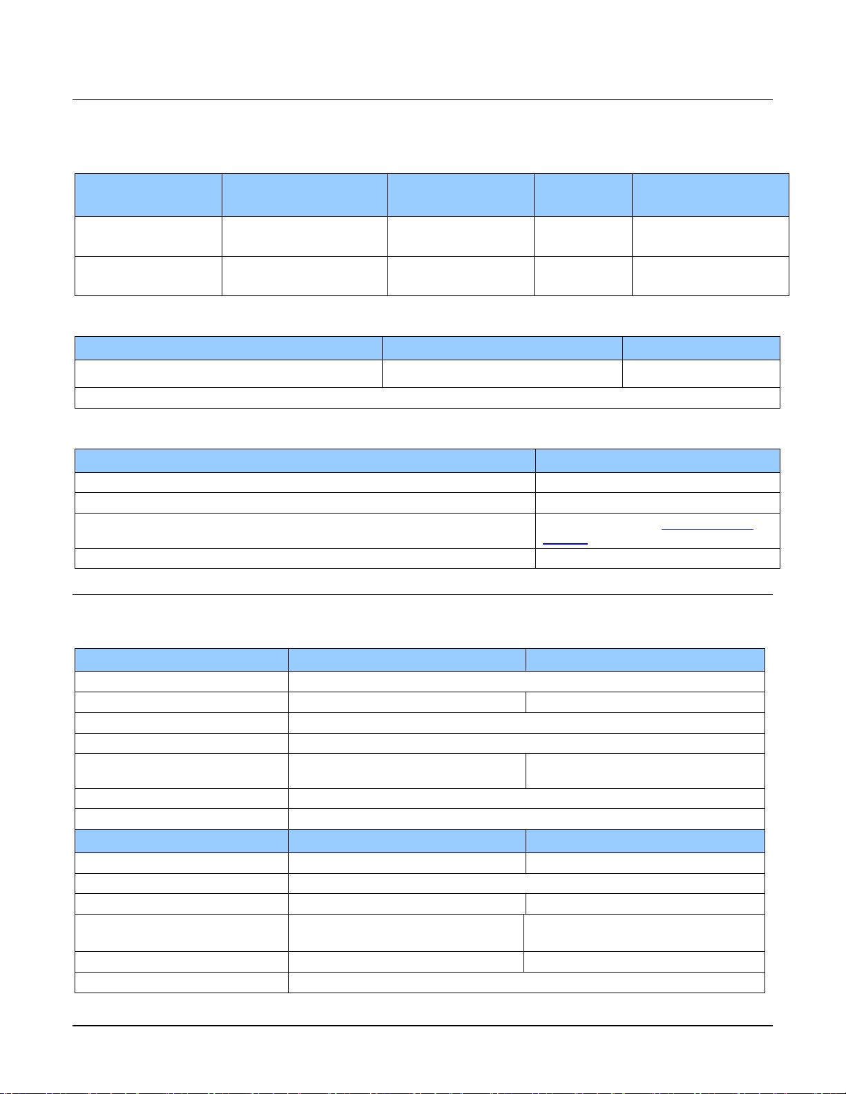
Available Camera Models
Part Number
Description
ML-FC-08K10T-00-R
8,192 x 3 pixels, maximum line rate of 280 kHz aggregate (93 kHz x 3), 5 µm x 5 µm pixel size,
RGB output, CLHS LC fiber optic control & data connector. 300 kHz line rate achievable using
AOI.
ML-HC-16K10T-00-R
16,384 x 3 pixels, maximum line rate of 300 kHz aggregate (100 kHz x 3), 5 µm x 5 µm pixel
size, RGB output, CLHS CX4 control & data connector.

The Linea ML Color Camera 5
Camera Highlights
Key Features
Highly responsive multiline CMOS
Trilinear RGB
8K or 16K pixel resolution
Up to 300 kHz line rates
Very low noise
Bi-directionality with fixed optical center
Binning
Small form factor
Robust Camera Link HS interface
LC fiber optic (8K) or CX4 (16K) Camera Link HS control & data connector
Smart lens shading correction
High dynamic LUT mode
Programmability
Adjustable responsivity and white balancing
Spatial correction including sub pixel adjustment
Parallax correction
Multiple areas of interest for data reduction
Region of interest for easy calibration of lens and shading correction
Test patterns & diagnostics
Applications
Flat-panel LCD and OLED display inspection
Web inspection
Printed circuit board inspection
Printed materials
High throughput and high-resolution applications
6 The Linea ML Color Camera
Part Numbers and Software Requirements
The camera is available in the following configurations:
Table 1: Camera Models Comparison
Part Number
Resolution
Max. Line Rates
Pixel Size
Control & Data
Connector
ML-FC-08K10T-00-R
8,192 x 3 pixels (RGB)
280 kHz (93 kHz x 3)
300 kHz using AOI
5.0 x 5.0 µm
Camera Link HS
LC fiber optic
ML-HC-16K10T-00-R
16,384 x 3 pixels (RGB)
300 kHz (100 kHz x
3)
5.0 x 5.0 µm
Camera Link HS
CX4
Table 2: Frame Grabber
Compatible Frame grabber
ML-FC-08K10T
ML-HC-16K10T
Teledyne DALSA
OR-A8S0-FX840
OR-A8S0-PX870
Other compatible frame grabbers may be available from third-party vendors.
Table 3: Software
Software
Product Number / Version Number
Camera firmware
Embedded within camera
GenICam™ support (XML camera description file)
Embedded within camera
Sapera LT, including CamExpert GUI application and GenICam for Camera Link
imaging driver
Latest version on the TeledyneDALSA
Website
Camera Link HS
V 1.0
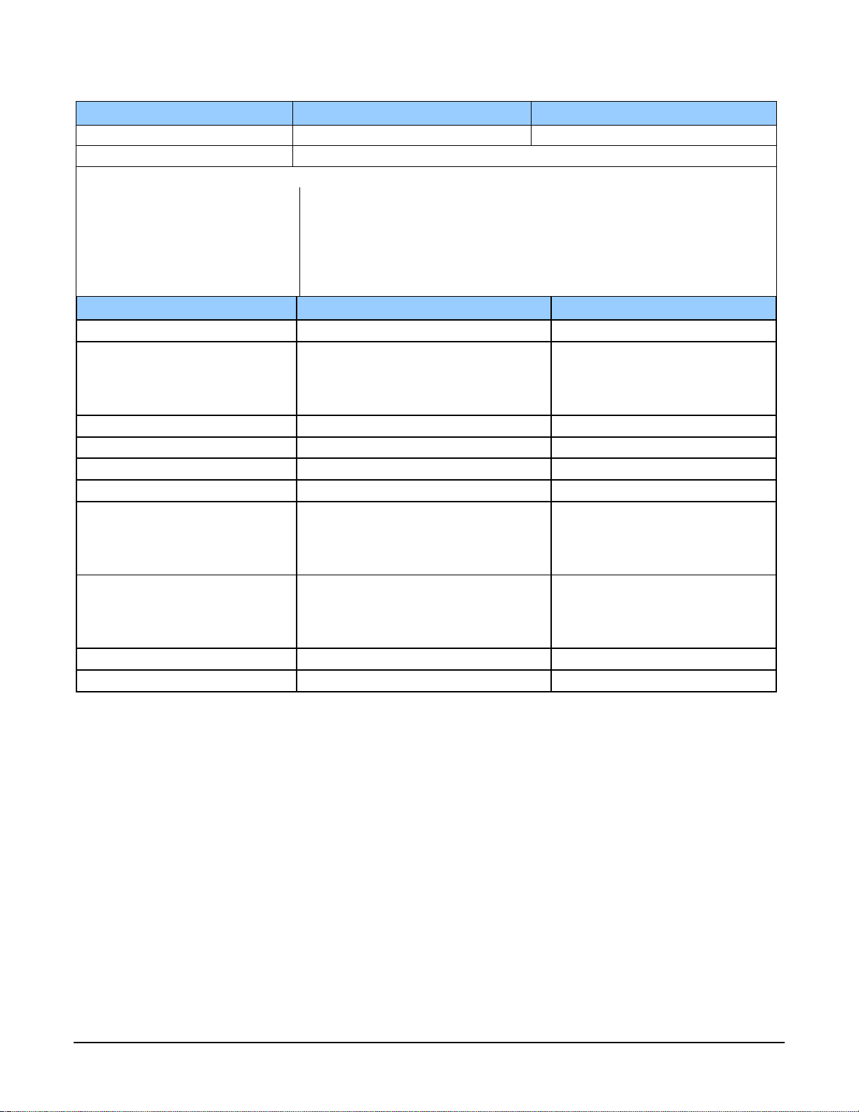
Performance Specifications
Table 4: Camera Performance Specifications
Specifications
ML-FC-08K10T
ML-HC-16K10T
Imager Format
High speed CMOS multiline trilinear
Resolution
8,192 pixels x 3 (Red + Green + Blue)
16,384 pixels x 3 (Red + Green + Blue)
Pixel Size
5.0 µm x 5.0 µm
Pixel Fill Factor
88 %
Line Rate
280 kHz aggregate (93 kHz x 3)
300 kHz achievable using AOI
300 kHz aggregate (100 kHz x 3)
Exposure Time
2.4 µs to 1,400 µs
Bit Depth
8 bit
Connectors and Mechanicals
ML-FC-08K10T
ML-HC-16K10T
Control & Data Interface
Camera Link HS LC fiber optic
Camera Link HS CX4
Power
+12 V to +24 V DC, Hirose 12-pin circular
Typical Power Dissipation1
16 W
28 W
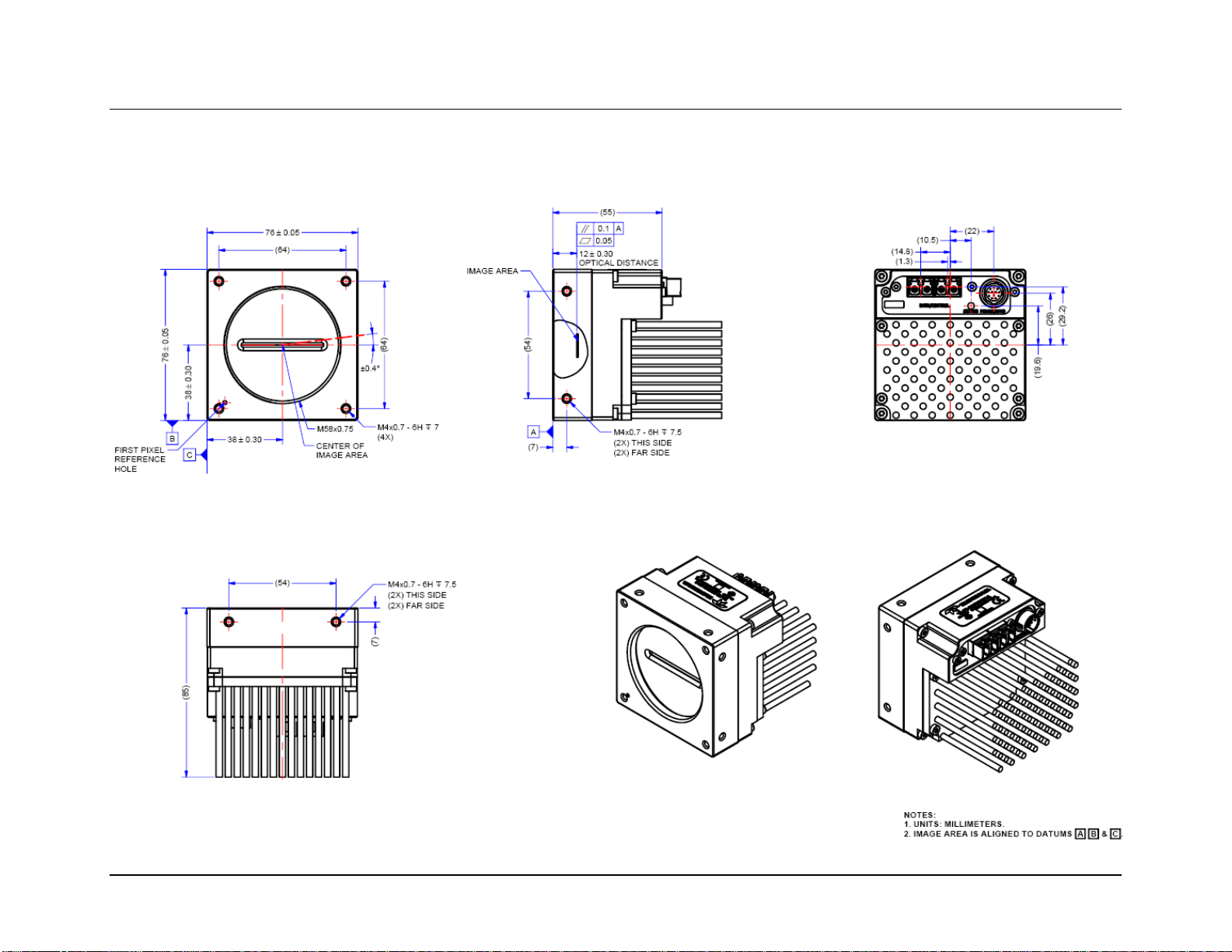
Size
76 mm (W) x 76 mm (H) x 85 mm (D)
97 mm (W) x 140.5 mm (H) x 78.6 mm
(D)
Mass
< 500 grams
< 1.2 kilograms
Operating Temp
+0 °C to +65°C, front plate temperature2
The Linea ML Color Camera 7
Optical Interface
ML-FC-08K10T
ML-HC-16K10T
Lens Mount
M58 x 0.75 mm
M90 x 1 mm
Sensor to Camera Front Distance
12 mm
Sensor Alignment (aligned to sides of camera)
Flatness
y (parallelism)
x
y
z
z
50 µm
100 µm
± 100 µm
± 100 µm
± 250 µm
± 0.4°
Operating Ranges
Performance (All models)
Notes
Random Noise*
< 0.3 DN rms (10 e-)
typical
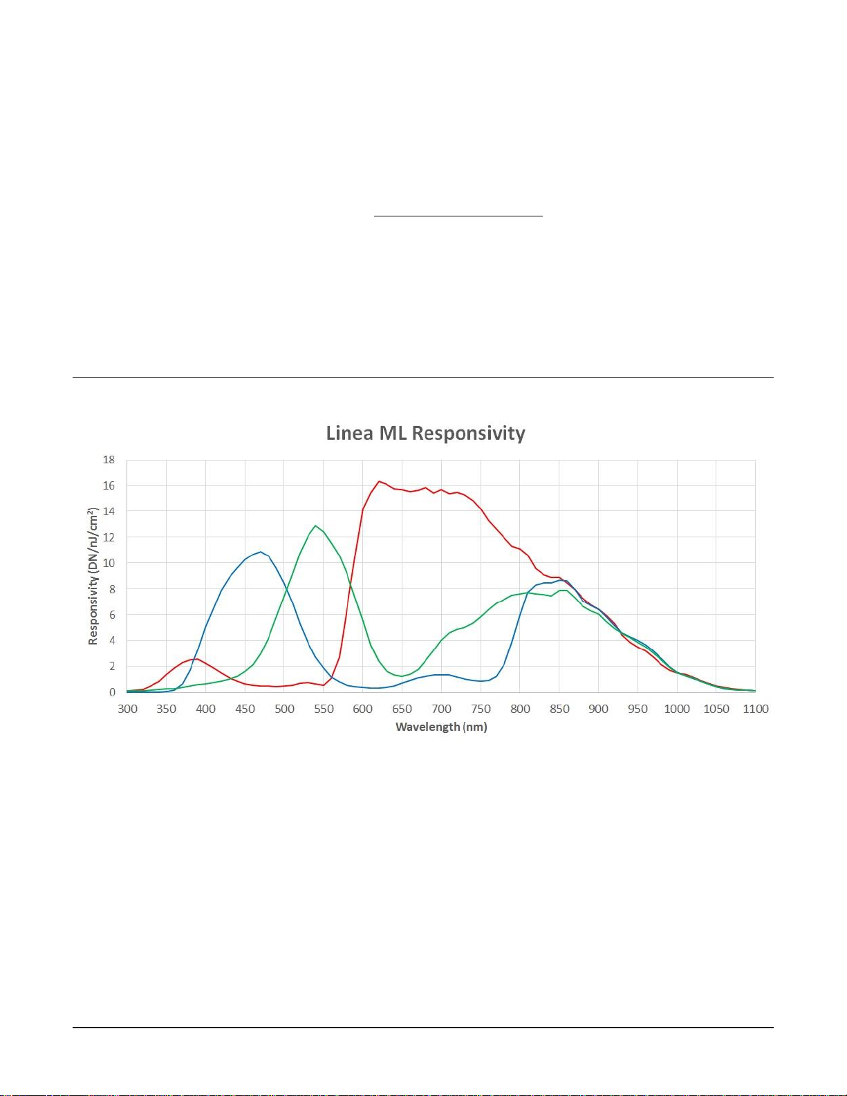
Peak Responsivity
Blue
Green
Red
12 DN/(nJ/cm2)
13 DN/(nJ/cm2)
18 DN/(nJ/cm2)
@ 460 nm
@ 525 nm
@ 625 nm
DC Offset
5 DN
Can be adjusted as required
Full Well
7,200 e-
Typical, single row
PRNU
< ±2%
50% of calibration target
DSNU (FPN)
< ±2 DN
SEE
Blue
Green
Red
21 nJ/cm
2
19 nJ/cm
2
14 nJ/cm2
@ 460 nm
@ 525 nm
@ 625 nm
NEE
Blue
Green
Red
15 pJ/cm
2
12 pJ/cm
2
10 pJ/cm
2
RN / Responsivity
@ 460 nm
@ 525 nm
@ 625 nm
Anti-blooming
> 100x Saturation
Integral non-linearity
< 2%
8 The Linea ML Color Camera
Notes:
*DN = digital number
1. Power dissipation increases with temperature. See Figure 1: Power and TemperatureFigure 1.
2. Camera will shut down when the internal temperature reaches +80 ºC.
Test Conditions unless otherwise specified:
Note: Specifications are under specified operating conditions and may degrade as
temperature limits are approached.
Values measured using 8-bit, 1x gain.
40 kHz line rate.
Light source: White LED if wavelength not specified.
Front plate temperature: +45º C.
Environmental Specifications
Storage temperature range
-20 °C to +80 °C
Humidity (storage and operation)
15% to 85% relative, non-condensing
MTBF (mean time between failures)
> 100,000 hours, typical field operation
Flash Memory Size
Table 5: Camera Flash Memory Size
Camera
Flash memory size
All models
4 GByte
Certification & Compliance
Table 6: Camera Certification & Compliance
Compliance
See the Declaration of Conformity section at the end of this manual.
KC Registration
Verified equipment registered under the Clause 3, Article 58-2 of Radio Waves Act. ML-FC-08K10T registration no. R-RTd2-ML-FC-08K10T. Registration date 2018-12-28. ML-HC-16K10T registration pending.
The Linea ML Color Camera 9
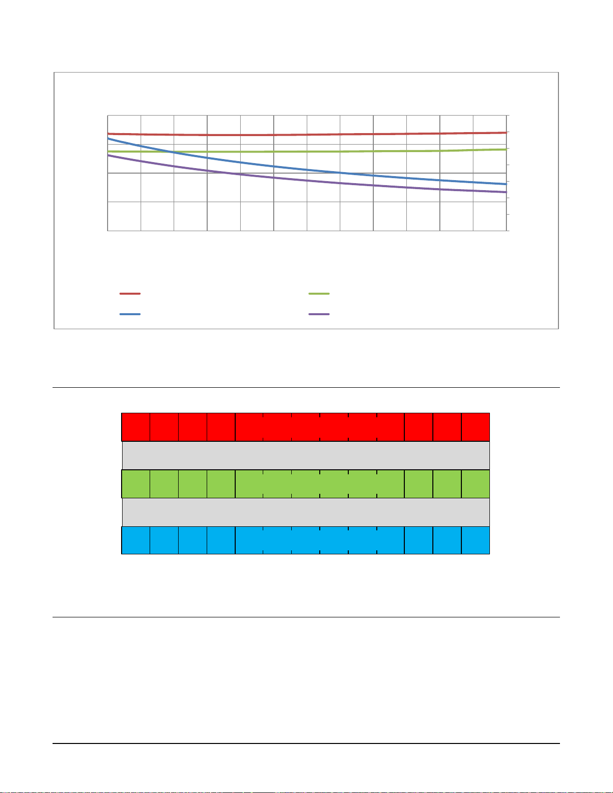
Figure 1: Power and Temperature*
*Measured using ML-HC-16K camera and showing ambient temperatures.
Camera Pixel Arrangement
5 µm or 1 line spacing
5 µm or 1 line spacing
5 µm x 5 µm Red Pixels
5 µm x 5 µm Blue Pixels
5 µm x 5 µm Green Pixels
Figure 2: ML-FC-08K10T and ML-HC-16K10T Color Pixel Structure
Forward and reverse imaging does not cause the optical center to change. Exposure control allows
inspection speed to change without changing responsivity.
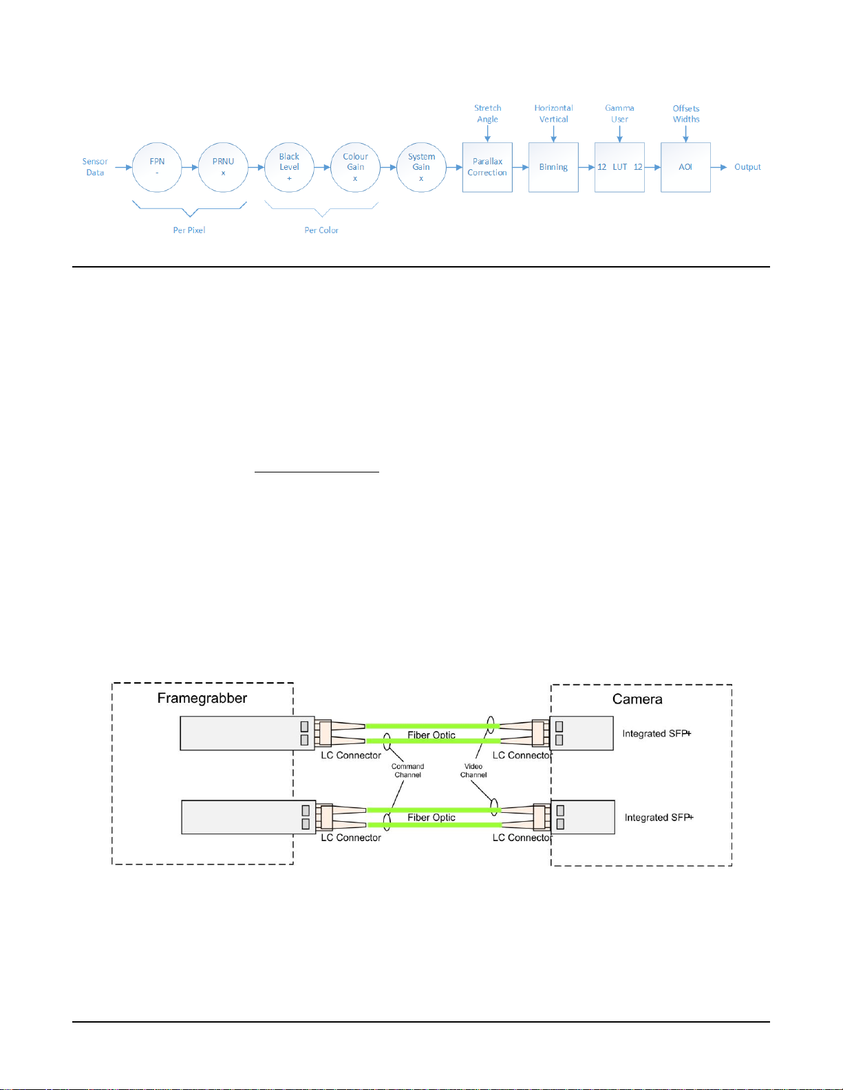
Camera Processing Chain
The diagram below details the sequence of arithmetic operations performed on the cameras sensor
data, which the user can adjust to obtain an optimum image for their application. These
adjustments are performed using camera features outlined in the ‘Review of Camera Performance
and Features’ section.
0.0
0.5
1.0
1.5
2.0
2.5
3.0
3.5
0
10
20
30
40
12 13 14 15 16 17 18 19 20 21 22 23 24
Current (A)
Power (W)
Voltage (V)
Camera Input Power
Power @ 65°C (W) Power @ 25°C (W)
Camera Input Current @ 65°C (A) Camera Input Current @ 25°C (A)
10 The Linea ML Color Camera
Supported Industry Standards
GenICam™
The camera is GenICam compliant and implements a superset of the GenICam Standard Features
Naming Convention specification V1.5.
This description takes the form of an XML device description file using the syntax defined by the
GenApi module of the GenICam specification. The camera uses the GenICam Generic Control
Protocol (GenCP V1.0) to communicate over the Camera Link HS command lane.
For more information see www.genicam.org.
Camera Link HS
The camera is Camera Link HS (version 1.0) compliant. Camera Link HS is the next generation of
high performance communications standards. It is used where an industrial digital camera
interfaces with a single or multiple frame grabber and with data rates exceeding those supported
by the standard Camera Link.
The cameras come with two different output mediums. For the 8K camera it uses two LC
connectors for data output. These two LC connectors are part of the SFP+ standard but in the case
of the 8K camera the SFP+ modules are built into the camera. Either one or both SFP+ modules
can be used but using only one SFP+ / Fibre optic will sacrifice available bandwidth.
Figure 3.Linea HS 8K Dual LC/SFP+ Connector Configuration
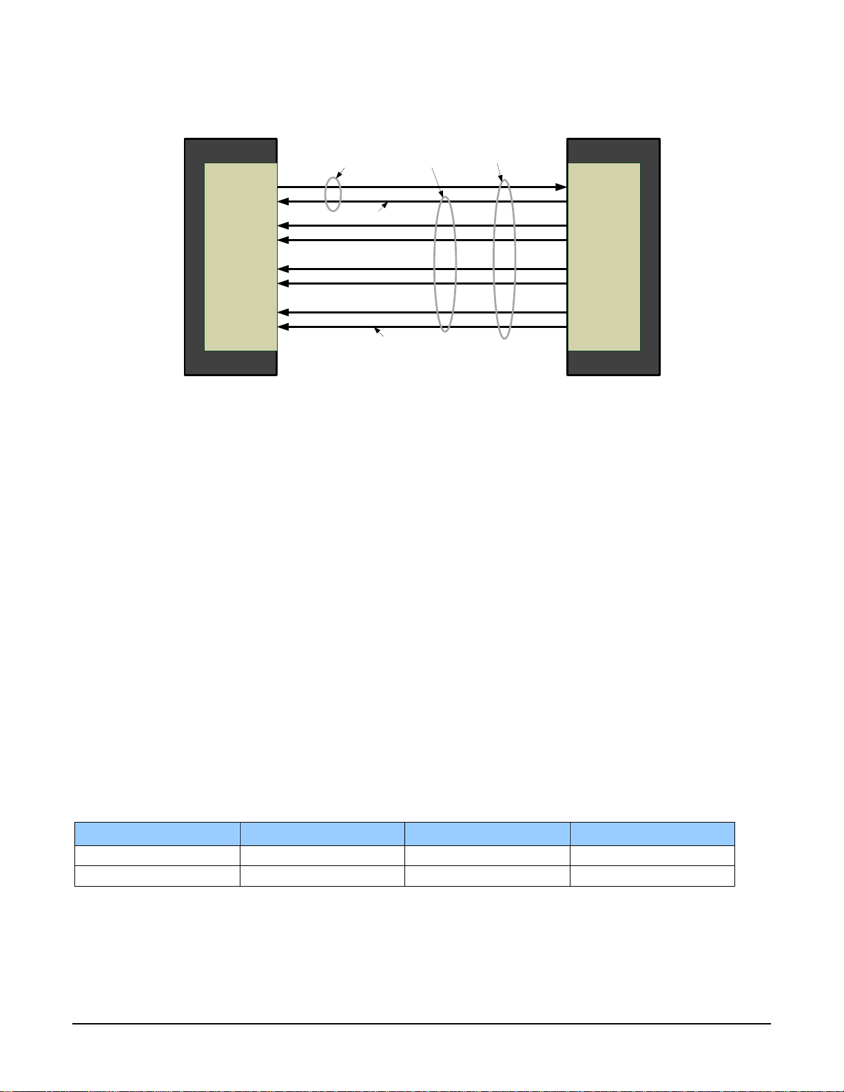
For the 16K camera, it uses a CX4 connector for the output using up to 5 lanes.
The Linea ML Color Camera 11
Figure 4. Single CX4 CLHS Connector Configuration
The command channel is used by the frame grabber to send commands, configuration, and
programming data to the camera and to receive command responses, status, and image data from
the camera. With two SFP+ modules populated, the CLHS protocol will auto negotiate which one
will be dedicated as the command channel. Data and command transmission is done with CLHS X
protocol (64b / 66b) at the default speed of 10 Gbs.
Data Cables
LC Fiber Optic (8K Cameras)
The fiber optic cables for the 8K camera require LC connections on both ends of the cable. The
frame grabber requires the LC connector to be plugged into a SFP+ transceiver module.
LC is a small-form factor fiber optic connector that uses a 1.25 mm ferrule, half the size of a
standard connector. These cables are in wide use in the telecommunications industry and available
in many lengths.
The distance through which the data can be transmitted depends on the type of fiber optic used.
Recommended fiber optic cables are types OM3 and OM4.
OM4 is used for distances > 300 m, but also requires SFP+ transceiver module changes.
Contact Teledyne DALSA Support for more information.
Category
Fiber Diameter
Mode
Max Distance
OM3
50 µm
Multimode
< 280 m
OM4
50 µm
Multimode
> 300 m
CX4 AOC (16K Cameras)
For the 16K camera, the Camera Link HS CX4 AOC (Active Optical Cable) cables are made to
handle very high data rates. These cables accept the same electrical inputs as traditional copper
cables, but also use optical fibers. AOC uses electrical-to-optical conversion on the cable ends to
RXC
TXC
TX1
TX2
TX3
TX4
TX5
TX6
TXC
RXC
RX1
RX2
RX3
RX4
RX5
RX6
Data Lane 6
Data Lane 0
Command
Channel
Video
Channel
Link
Camera
(C2,7M1)
Frame Grabber
(C2,7M1)
12 The Linea ML Color Camera
improve speed and distance performance of the cable without sacrificing compatibility with
standard electrical interfaces.
Camera Link HS cables can be bought from an OEM. OEM cables are also available for applications
where flexing is present.
Please refer to Teledyne DALSA’s website (www.teledynedalsa.com) for a list of recommended
cable vendors and for part numbers.
Each data cable is used for sending image data to and accepting command data from the frame
grabber. Command data includes GenICam compliant messages, trigger timing, and general
purpose I/O, such as direction control.
Please note: the data transmits at 10 Gbps which limits the effective distance of copper-based
cables.
Responsivity
Note: values measured using 8-bit, 1x gain, single row.
The Linea ML Color Camera 13
Mechanical Drawings
ML-FC-08K10T-00-R
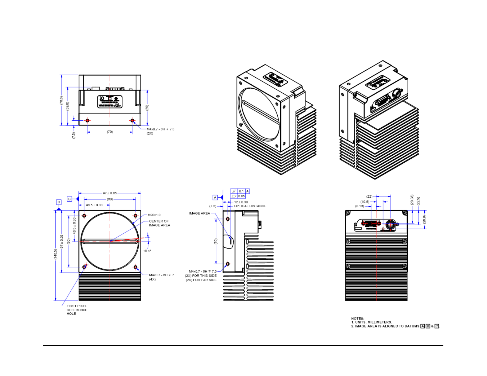
14 The Linea ML Color Camera
ML-HC-16K10T-00-R

The Linea ML Color Camera 15
Precautions
Read these precautions carefully before using the camera.
Confirm that the camera’s packaging is undamaged before opening it. If the packaging is damaged
please contact the related logistics personnel.
Do not open the housing of the camera. The warranty is voided if the housing is opened.
Keep the camera’s front plate temperature in a range of 0 °C to +65 °C during operation. The
camera can measure its internal temperature. Use this feature to record the internal temperature
of the camera when it is mounted in your system and operating under the worst-case conditions.
The camera will shut down if its internal temperature reaches +80 °C.
Do not operate the camera near strong electromagnetic fields. In addition, avoid electrostatic
discharging, violent vibration, and excess moisture.
To clean the device, avoid electrostatic charging by using a dry, clean absorbent cotton cloth
dampened with a small quantity of pure alcohol. Do not use methylated alcohol. To clean the
surface of the camera housing, use a soft, dry cloth. To remove severe stains, use a soft cloth
dampened with a small quantity of neutral detergent and then wipe dry. Do not use volatile
solvents such as benzene and thinners, as they can damage the surface finish. Further cleaning
instructions are below.
It is recommended that you power down and disconnect power to the camera before you add or
replace system components.
Electrostatic Discharge and the CMOS Sensor
Image sensors and the camera’s housing can be susceptible to damage from severe electrostatic
discharge (ESD). Electrostatic charge introduced to the sensor window surface can induce charge
buildup on the underside of the window. The charge normally dissipates within 24 hours and the
sensor returns to normal operation.
Install & Configure Frame Grabber & Software
Because of the high bandwidth required by this camera, we recommend a compatible Teledyne
DALSA frame grabber (OR-A8S0-FX840 or OR-A8S0-PX870), or equivalent, described in detail on
the teledynedalsa.com site here. Follow the manufacturer’s installation instructions.
A GenICam compliant XML device description file is embedded within the camera firmware and
allows GenICam compliant applications to recognize the camera’s capabilities following connection.
Installing Sapera LT gives you access to the CamExpert GUI, a GenICam compliant application.
Using Sapera CamExpert
CamExpert is the camera interfacing tool supported by the Sapera library. When used with the
camera, CamExpert allows a user to access a camera’s features and parameters, and to test the
operating modes. In addition, CamExpert can be used to save the camera’s user settings
configurations to the camera. Or saves multiple configurations as individual camera parameter files
on the host system (*.ccf). CamExpert can also be used to upgrade the camera’s software.
16 The Linea ML Color Camera
An important component of CamExpert is its live acquisition display window. This window allows
the user to immediately verify the timing or control parameters without needing to run a separate
acquisition program.
For context sensitive help, click on the button and then click on a camera configuration
parameter.
A short description of the configuration parameter will be shown in a popup. Click on the
button to open the help file for more descriptive information on CamExpert.
Note: The availability of features depends on the CamExpert user setting. Not all features are
available to all users.
A note on the CamExpert examples shown here: The examples shown are for illustrative purposes and may not entirely reflect the
features and parameters available from the camera model used in your application.
The Linea ML Color Camera 17
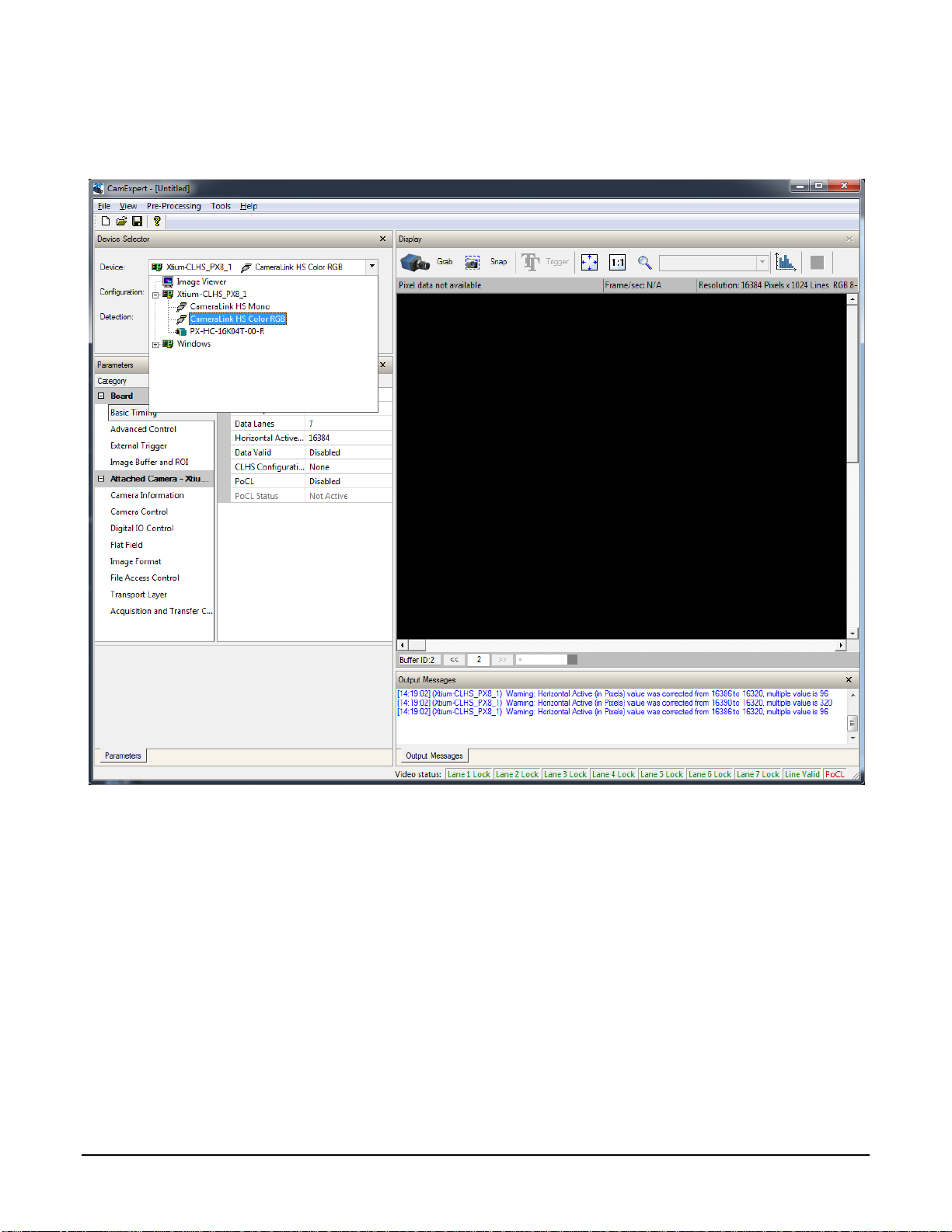
CamExpert Panes
CamExpert, first instance: select Camera Link HS RGB using the Device drop-down menu.
Figure 5. CamExpert Frame Grabber Control Window
The CamExpert application uses panes to organize the selecting and configuring of camera files or
acquisition parameters.
Device Selector pane: View and select from any installed Sapera acquisition device. Once a
device is selected, CamExpert will only show acquisition parameters related to that device.
Optionally, select a camera file included with the Sapera installation or saved by the user.
Parameters pane: Allows the viewing or changing of all acquisition parameters supported by the
acquisition device. CamExpert displays parameters only if those parameters are supported by the
installed device. This avoids confusion by eliminating parameter choices when they do not apply to
the hardware in use.
Display pane: Provides a live or single frame acquisition display. Frame buffer parameters are
shown in an information bar above the image window.

18 The Linea ML Color Camera
Control Buttons: The Display pane includes CamExpert control buttons. These are:
Acquisition control button:
Click once to start a live grab, click again to stop.
Single frame grab:
Click to acquire one frame from device.
Trigger button:
With the I/O control parameters set to Trigger Enabled, click to send a
single trigger command.
CamExpert display controls:
(these do not modify the frame buffer data)
Stretch image to fit, set image display to original size, or zoom the
image to virtually any size and ratio.
Histogram / Profile tool:
Select to view a histogram or line/column profile during live
acquisition or in a still image.
Output Message pane: Displays messages from CamExpert or the device driver.
At this point you are ready to start operating the camera to acquire images, set camera functions,
and save settings.
The Linea ML Color Camera 19
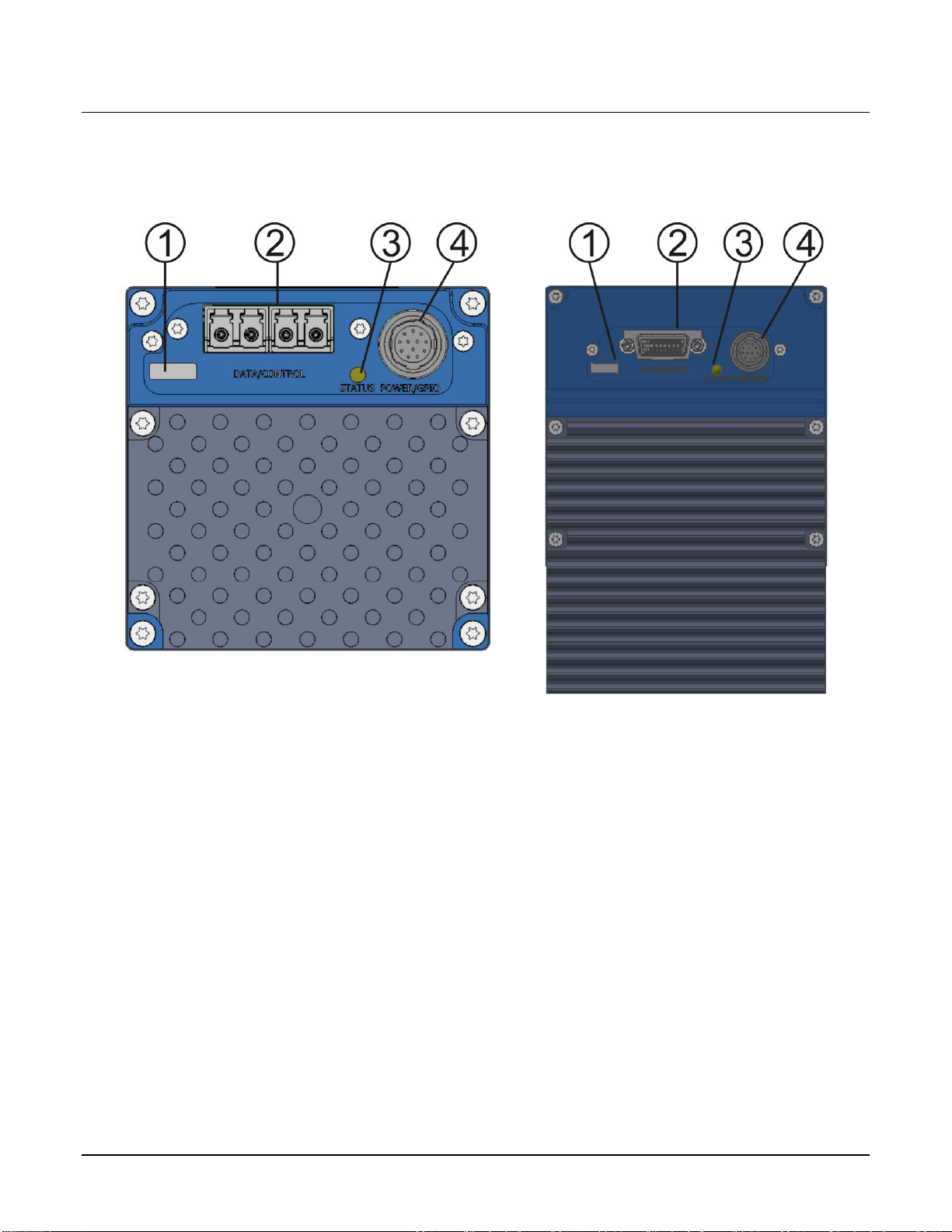
Setting Up for Imaging
Figure 6. Camera I / O Connectors: 8K (left) & 16K (right)
Camera I / O Connectors
1) Factory use only.
2) Data and control connectors: LC (8K) and CX4 (16K).
3) LED status indicators.
4) Power and GPIO connectors: +12 V to +24 V DC, Hirose 12-pin circular.
Powering the Camera
WARNING: When setting up the camera’s power supply follow these guidelines:
Apply the appropriate voltages of between +12 V to +24 V. Incorrect voltages may damage
the camera.
Before connecting power to the camera, test all power supplies.
Protect the camera with a 3-amp slow blow fuse between the power supply and the camera.
Do not use the shield on a multi-conductor cable for ground.
Keep leads as short as possible to reduce voltage drop.
20 The Linea ML Color Camera
Use high quality supplies to minimize noise.
When using a +12 V supply, voltage loss in the power cables will be greater due to the
higher current. Use the Camera Information category to refresh and read the camera’s input
voltage measurement. Adjust the supply to ensure that it reads above or equal to +12 V.
Note: If your power supply does not meet these requirements, then the camera performance
specifications are not guaranteed.
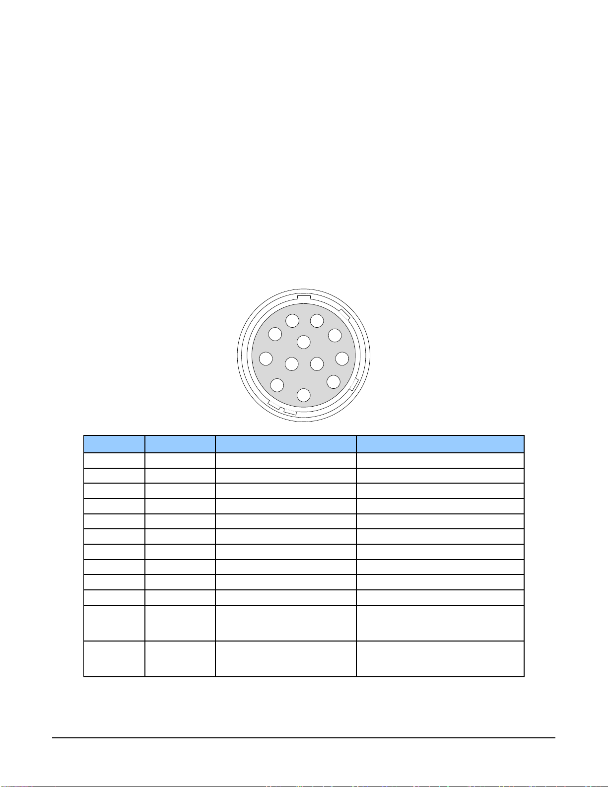
Power and GPIO Connections
The camera uses a single 12-pin Hirose male connector for power, trigger, and strobe signals. The
suggested female cable mating connector is the Hirose model HR10A-10P-12S.
12-Pin Hirose Connector Signal Details
The following figure shows the pinout identification when looking at the camera’s 12-pin male
Hirose connector. The table below lists the I/O signal connections.
1
4
6
7
1211
3
2
10
8
9
5
Pin Number
Input / Output
Signal Details
Notes
1 Power Ground*
2
+12 V to +24 V power*
3
Output
Line 3 Out
0 to 3.3V TTL
4
Output
Line 4 Out
0 to 3.3V TTL
5
Input
Line 1/ Trigger / Phase A
0 to 3.3V TTL
6
Input
Line 2 / Scan Direction/Phase B
0 to 3.3V TTL
7
Output
Line 5 Out
0 to 3.3V TTL
8
Output
Line 6 Out
0 to 3.3V TTL
9 Power Ground*
10 +12 V to +24 V power*
11 Signal Ground
Note: intended as a return path for
GPIO signal and not intended as a
power ground
12 Signal Ground
Note: intended as a return path for
GPIO signal and not intended as a
power ground
*Connect all power pins. Each pin is rated 2A.
The Linea ML Color Camera 21
The wire gauge of the power cable should be sufficient to accommodate a surge during power-up of
at least 3 amps with a minimum voltage drop between the power supply and camera. The camera
can accept any voltage between +12 Volts and +24 Volts. If there is a voltage drop between the
power supply and camera, ensure that the power supply voltage is at least 12 Volts plus this
voltage drop. The camera input supply voltage can be read using CamExpert. Refer to the section
on Voltage & Temperature Measurement for more details.
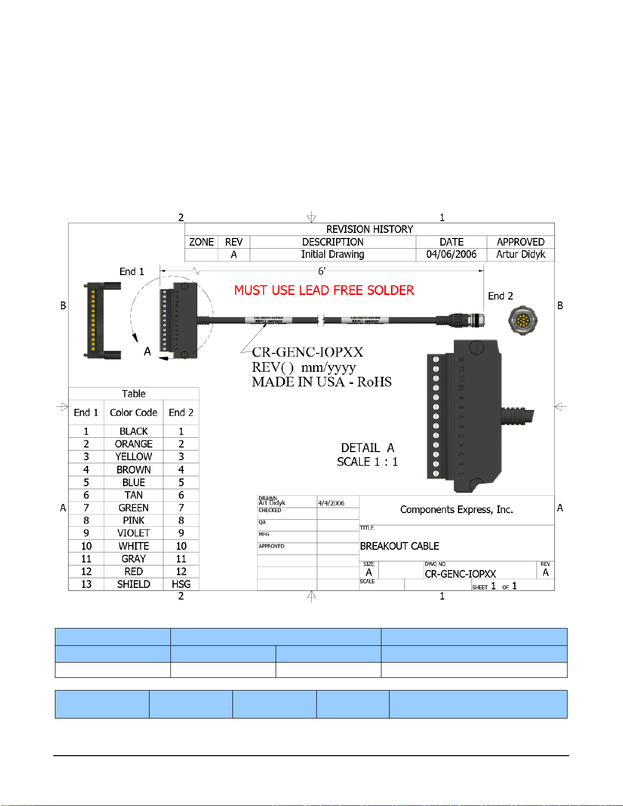
Mating GPIO Cable Assembly
Teledyne DALSA makes available for purchase an optional GPIO breakout cable (12-pin Female
Hirose to 13-Pos Euro Block), as shown in the following drawing. Use accessory number #CRGENC-IOP00 to order.
External Input Electrical Characteristics
Switching Voltage
Input Level Standard
Low to high
High to low
Input Impedance
3.3 V TTL
2.1 V
1 V
10K Ω
External Input Timing Reference
Input Level
Standard
Maximum Input
Frequency
Minimum Pulse
Width
Input Current
Maximum Signal Propagation Delay @
60oC
 Loading...