

Teledyne Linea 2K CL, Linea 8k CL, Linea 4k CL, Linea 16K CL User Manual
Linea
™
CL
Camera User’s Manual
sensors |
cameras
| frame grabbers | processors | software | vision solutions
2k, 4k, 8k and 16k Monochrome CMOS Line Scan
P/N: 03-032-20206-02
www.teledynedalsa.com

Notice
Revision
Description
Date
00
Initial release.
April 6, 2014.
01
8K and 16K models descriptions and features added .
December 4, 2 014
-Updated manual format and corrected errors.
© 2015 Teledyne DALSA
All information provided in this manual is believed to be accurate and reliable. No
responsibility is assumed by Teledyne DALSA for its use. Teledyne DALSA reserves the right
to make changes to this information without notice. Reproduction of t his m anual in whole or
in part, by any means, is prohibited without prior permission having been obtained from
Teledyne DALSA .
Microsoft and Windows are registered trademarks of M icro soft Corporation in the United
States and other countries. Windows, Windows 7, Windows 8 are trademarks of Microsoft
Corporation.
All other trademarks or intellectual property mentioned herein belong to their respective
owners.
Document Number: 03-032-20206-02
02 -Maximum line rate for the 16K model revised from 50 kHz to 48 kHz.
-16K responsi vity revised to 66 DN from 80 DN.
-8K and 16K mass revised to < 36 0 g from < 250 g.
-16K power dissipation revised to < 11 W from < 14 W.
July 16, 2015
About Teledyne DALSA
Teledyne DALSA is an international high performance semiconductor and electronics
company that designs, develops, manufactures, and markets digital imaging products and
solutions, in addition to providing wafer foundry services.
Teled y n e DALSA Digital Imaging offers the widest range of machine vision components in
the world. From industry-leading image sensors through powerful and sophisticated
cameras, frame grabbers, vision processors and software to easy-to-use vision appliances
and custom vision modules.

Contents
LINEA™ CL SERIES OVERVIEW ...................................................................... 4
DESCRIPTION ................................................................................................ 4
CAMERA HIGHLIGHTS ....................................................................................... 5
Key Features ......................................................................................... 5
Programmability ..................................................................................... 5
Applications ........................................................................................... 5
PART NUMBERS AND SOFTWARE REQUIREMENTS ....................................................... 6
CAMERA SPECIFICATIONS OVERVIEW ..................................................................... 7
Compliance, EMI Certifications ................................................................. 8
SUPPORTED INDUSTRY STANDARDS ....................................................................... 9
GenICam™ ............................................................................................ 9
ASCII COMMANDS .......................................................................................... 9
RESPONSIVITY ............................................................................................. 10
Effective Quantum Efficiency: ................................................................ 11
LINEA CL CAMERA SETUP ............................................................................ 12
SYSTEM PRECAUTIONS AND CLEANING ................................................................. 12
Precautions ......................................................................................... 12
Cleaning the Device .............................................................................. 12
Electrostatic Discharge and the CMOS Sensor .......................................... 12
RECOMMENDED SYSTEM REQUIREMENTS ............................................................... 12
SETUP STEPS: OVERVIEW ................................................................................ 13
Step 1: Install and Configure Frame Grabber and Softw are ....................... 13
Step 2: Connect Camera Link and Power Cables ....................................... 13
Step 3: Establish Communication with the Camera ................................... 16
USING CAMEXPERT WITH LINEA CL CAMERAS ............................................ 18
CamExpert Panes ................................................................................. 18
Creating a Camera Configuration File in the Host...................................... 20
CAMERA OPERATION ................................................................................... 21
FACTORY SETTINGS ....................................................................................... 21
TYPICAL SETUP AND EVALUATION ....................................................................... 22
Optical Configuration ............................................................................ 22
Camera Timing & Control ...................................................................... 22
Acquiring an Image .............................................................................. 22
CHECK CAMERA AND SENSOR INFORMATION .......................................................... 23
Verify Temperature and Voltage ............................................................. 23
Camera Configuration Selection Dialog .................................................... 24
SET BAUD RATE ........................................................................................... 26
CAMERA LINK CONFIGURATION .......................................................................... 27
Pixel Format ........................................................................................ 28
INTERNAL TEST IMAGE GENERATOR ..................................................................... 28
CALIBRATING THE CAMERA ............................................................................... 29
Flat Field Parameters ............................................................................ 30
TRIGGER MODES .......................................................................................... 32
EXPOSURE CONTROLS .................................................................................... 33
Linea CL Series Camera Contents • 1

GAIN AND BLACK LEVEL (OFFSET) ...................................................................... 37
BINNING .................................................................................................... 38
PIXEL READOUT DIRECTION (MIRRORING MODE) .................................................... 39
AREA OF INTEREST (AOI) SETUP ....................................................................... 40
SAVING AND RESTORING CAMERA SETTINGS .......................................................... 43
Camera Configuration Selection Dialog .................................................... 43
CAMERA FIRMWARE UPDATES ............................................................................ 45
DOWNLOAD A LI ST OF CAMERA PARAMETERS .......................................................... 45
FILE ACCESS VIA T H E CAMEXPERT TOOL ............................................................... 46
RESETTING THE CAMERA ................................................................................. 47
TECHNICAL SPECIFICATIONS ...................................................................... 48
MECHANICAL SPECIFICATIONS ........................................................................... 48
2K and 4K Cameras .............................................................................. 48
8K and 16K Cameras ............................................................................ 49
ADDITIONAL NOTES ON LINEA CL IDE NTIFICATION AND MECHANICAL ............................. 50
EMC DECLARATIONS OF CONFORMITY ................................................................. 50
ADDITIONAL REFERENCE INFORMATION .................................................... 53
OPTICAL CONSIDERATIONS .............................................................................. 53
Illumination ......................................................................................... 53
Light Sources ....................................................................................... 53
Lens Modeling ...................................................................................... 54
Magnification and Resolution ................................................................. 54
SENSOR HANDLING INSTRUCTIONS ..................................................................... 55
Electrostatic Discharge and the Sensor ................................................... 55
Protecting Against Dust, Oil and Scratches .............................................. 55
Cleaning the Sensor Window ................................................................. 56
APPENDIX A: GENICAM COMMANDS ............................................................ 57
CAMERA INFORMATION CATEGORY ...................................................................... 57
Camera Information Feature Descriptions ................................................ 57
CAMERA CONTROL CATEGORY ........................................................................... 60
Camera Control Feature Descriptions ...................................................... 60
I/O CONTROLS CATEGORY ............................................................................... 61
I/O Control Feature Descriptions ............................................................ 61
FLAT FIELD CATEGORY .................................................................................... 62
Flat Field Feature Descriptions ............................................................... 62
IMAGE FORMAT CONTROL CATEGORY ................................................................... 63
Image Format Control Feature Description .............................................. 63
TRANSPORT LAYER CATEGORY ........................................................................... 65
Transport Layer Descriptions ................................................................. 65
DEVICE STREAMING REGISTERS ......................................................................... 66
Start – End Command Requirements ...................................................... 66
FILE ACCESS CONTROL CATEGORY ...................................................................... 66
File Access Control Feature Descriptions .................................................. 66
APPENDIX B: AS CII COMMANDS ................................................................. 68
ACCESSING THE THREE LETTER COMMANDS (TLC) .................................................. 68
Port Configuration ................................................................................ 68
Notes on Using Alternatives to HyperTerminal .......................................... 69
ASCII TO GENCP ......................................................................................... 69
Disabling the Esc Key for Direct Access to ASCII Commands ...................... 69
2 • Contents Linea CL Series Camera

Commands .......................................................................................... 70
APPENDIX C: ERROR AND WARNING MESSAGES ......................................... 82
OPERATIONAL ERROR CODES ............................................................................ 83
APPENDIX D: CAMER A, F RAME GRABBER COMMUNICATION ....................... 84
Setting Up Communication between the Camera and the Frame
Grabber ......................................................................................... 84
APPENDIX E: CAMERA LINK CONNECTOR INFORMATION ............................ 86
DATA CONNECTOR: CAMERA LINK ...................................................................... 86
Full Configuration ................................................................................. 87
Camera Link Bit Definitions.................................................................... 89
Camera Control Configuration ................................................................ 90
CAMERA LINK DRIVE CAPABILITY ....................................................................... 90
Input Signals, Camera Link.................................................................... 90
Output Signals, Camera Link Clocking Signals .......................................... 91
CONTACT INFORMATION ............................................................................. 92
SALES INFORMATION ...................................................................................... 92
TECHNICAL SUPPORT ...................................................................................... 92
Linea CL Series Camera Contents • 3
Linea™ CL Series Overview
Description
Teledyne DALSA introduces a new CMOS camera family with the 2K, 4K, 8K, and 16K resolution
Linea monochrome cameras. These new camera models use Teledyne DALSA's single line, 7.04
µm x 7.04 µm (2k, 4k, 8k) or 3.52 µm x 3.52 µm (16k) pixel array, delivering both speed and
responsivity at a competitive price.
The Linea CL linescan is a new affordable single line, camera delivering both speed and
responsivity at a competitive price. Th is small, low power camera is designed for application s such
as materials grading and inspection, transportation s a fety, automated optical inspection and
general purpose machine vision.
The Linea CL camera, is one of a new series of affordable easy to use digital cameras specifically
engineered for industrial imaging applications requiring embedded image processing and improved
network integration. Linea CL provides features to cycle a user defined sequence of imaging
setups, features providing line & frame triggers, image transfer-on-demand, all part of a
comprehensive camera package.
Linea uses industry standard CameraLink protocol to dependably capture and transfer images from
the camera to the host PC.
4 • Linea™ CL Series Overview Linea CL Series Camera

Camera Highlights
Teledyne DALSA introduces a new CMOS camera family with the 2K, 4K, 8K, and 16K resolution
Linea monochrome cameras. These new camera models use Teledyne DALSA's single line, 7.04
µm x 7.04 µm (2k, 4k, 8k) or 3.52 µm x 3.52 µm (16k) pixel array, delivering both speed and
responsivity at a competitive price.
These small, affordable, low power cameras are designed for applications such as materials grading
and inspection, transportation safety, automated optical inspection and general purpose machine
vision.
Key Features
• High speed: up to 80 kHz (2k, 4k, 8k) and 48 kHz (16k)
• 2048, 4096, 8192, and 16,384 pixel resolutions
• Compact camera body
Programmability
• Multiple regions of interest for calibration and data reduction
• 8 bit or 12 bit output
• Small flat field and lens shading correction
• 8 programmable coefficient sets
• GenICam or ASCII compliant interfacing
Applications
• Automated optical inspection
• Security systems
• High performance sorting systems
• Materials grading and inspection syste ms
• Web inspection
• General purpose machine vision
Linea CL Series Camera Linea™ CL Series Overview • 5
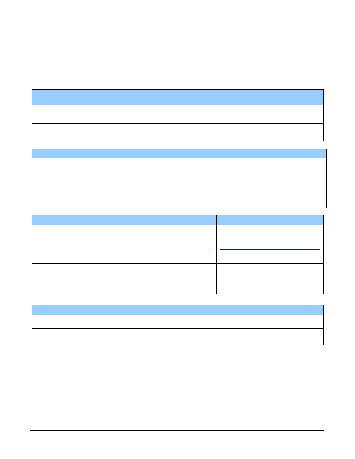
Part Numbers and Software Requirements
This manual covers the Linea CL models summarized below. New models area added to this
manual as they are released by Teledyne DALSA.
Camera Resolution Pixel size
Linea 2K CL 2048 x 1 7.04 x 7.04 µm
Linea 4k CL 4096 x 1 7.04 x 7.04 µm
Linea 8k CL 8192 x 1 7.04 x 7.04 µm
Linea 16K CL 16384 x 1 3.52 µm x 3.52 µm
Max. Line Rate Lens Mount
(threaded)
80 kHz M42 x 1 LA-CM-02K08A-xx-R
80 kHz M42 x 1 LA-CM-04K08A- xx -R
80 kHz M72 x 1 LA-CM-08K08A- xx -R
48 kHz M72 x 1 LA-CM-16K05A- xx -R
Camera Accessories Order Number
2K and 4k M42 x 1 to F-mount adapter for 12mm BFD lens, he avy d uty with clip AC-LA-00115-xx-R
2K and 4k M42 x 1 to C-mount adapter for 12 mm BFD lens AC-LC-00001-xx-R
8k and 16k M72 x 0.75 F, F-mount adapter 12 mm BFD lens, heavy duty AC-LN-0001-xx-R
8k and 16k Linea Heatsink AC-MS-00108-xx-R
For a list of accessories go to http://www.teledynedalsa.com/imaging/products/cameras/accessories/
Optical filters are available from http://www.midwestopticalsystems.com/
Teledyne DALSA Software Platform
Sapera LT version 7.50 or higher
includes CamExpert GUI application
Sapera provides everything needed to develo p imag ing applicatio ns .
Camera Firmware Embedded within camera
GenICam™ support (XML camera descrip tio n file ) Embedded within camera
Sapera Processing Imaging Developm e nt Libr ary
(available for Windows or Linux - sold separ a te ly):
Available for free download:
http://www.teledynedalsa.com/imaging/pr
oducts/software/sapera/lt/
Contact Teledyne DALSA Sales
Product Number
Third Party GenICam GenCP Software Requirements
Support of GenICam GenApi version 2.3 General acquisition and control. File access: firmware,
Support of GenICam XML schema version 1.1
GenICam™ support — XML camera description file Embedded within Linea CL
FFC, configuration data, upload & download.
6 • Linea™ CL Series Overview Linea CL Series Camera
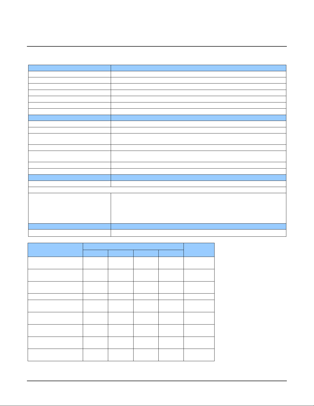
Specifications
Performance
Imager Format
High speed CMOS line scan
Resolution
2048, 4096, 8192, and 16,384 pixels
Pixel Size
7.04 µm x 7.04 µm (2k, 4k, 8k) and 3.52 µm x 3.52 µm (16k)
Pixel Fill Factor
100 %
Line Rate
Up to 80 kHz (2k, 4k, 8k) and up to 48 kHz (16k)
Exposure Time
4 µs to 3 ms
Bit Depth
8 bit or 12 bit, selectable
Connectors and Mechanicals
Control & Data Interface
Base, Medium, Full, and Deca Camera Link configur ati o ns (2 x SDR-26)
Power Connector
Hirose 6-pin male circular
+12 V to + 24 V DC (+11.4 V to +25.2 V maximum limits), 8k and 16k
Power Dissipation
< 4.5 W (2k and 4k), < 8 W (8k), < 11 W (16k)
76.0 mm (W) x 76.0 mm (H) x 36.7 mm (D) (8k and 16k)
Mass
< 190 g (2k and 4k), < 360 g (8k and 16k)
Operating Temp
0 °C to 65 °C, front plate temperature
Optical Interface
Sensor to Camera Front Distance
12 mm
Sensor Alignment (aligned to sides of camera)
Θ z
± 0.3°
Compliance
Regulatory Compliance
CE, FCC, and RoHS; GenICam
Operating Ranges
Performance
Notes
dB
DN* rms
DN / (nJ / cm2)
Gain Nominal range
1x to 10x
1x to 10x
1x to 10x
1x to 10x
DN
@ 50% Sat
DN
nJ / cm2
pJ / cm2
Camera Specifications Overview
Power Supply + 5 V to + 24 V DC (+4.8 V to +25.2 V maximum limits), 2k and 4k
Size 62.0 mm (W) x 62.0 mm (H) x 30.9 mm (D) (2k and 4k)
Θ y (parallelism)
x
y
z
Dynamic Range
Random Noise
Broadband Responsivity
DC Offset
PRNU
FPN
SEE
0.08° or 100 µm
± 300 µm
± 300 µm
± 300 µm
2K 4K 8K 16K
> 60 > 60 > 60 > 60
< 3.75 < 3.75 < 3.75 < 3.75 FFC enabled
320
7 7 7 7 FFC enabled
< 1.5% < 1.5% < 1.5% < 1.5%
< 7 < 7 < 7 < 7
12.5 12.5 12.5 46.9
320 320 80
NEE
11.7 11.7 11.7 51
Linea CL Series Camera Linea™ CL Series Overview • 7
Operating Ranges
Performance
Notes
Antiblooming
(x Saturation)
DN
2K 4K 8K 16K
> 100 > 100 > 100 > 100
Integral non-linearity
*DN = digital number
Test Conditions:
• Values measured using 12-bit @ 1x gain.
• 10 kHz line rate.
• Light source: broadband, quartz halogen, 3250 K with 700 nm IR cut-off filter.
• Front plate temperature: 45º C.
1.5 % 1.5 % 1.5 % 1 .5 %
Compliance, EMI Certifications
Compliance Directives Standards ID Overview
EN55032 (2012) Electromagnetic compatibil ity of multime dia
EN55011 (2009) with A1(2010) Industrial, scientific and medic al e quipment —
EN 61326-1 (2013) Electrical equipment for measurement, co ntrol and
CE
FCC
RoHS
For im ages of the Linea CL certificates see the EMC Declarations of Conformity section.
EN 55024 (2010) Information technology equipment —
CISPR 11 Industrial, scientific and medic al e quipment —
CISPR 32 Electromagnetic compatibil ity of multime dia
Part 15, class A
Compliancy as per European directive 2004 /105 /EC
equipment — Emission requirements
Radio-frequency disturbance characteristics —
Limits and methods of measurement
laboratory use — EMC requirements —
Part 1: General requirements
Immunity characteristics —
Limits and methods of measurement
Radio-frequency disturbance characteristics —
Limits and methods of measurement
equipment - Emission requirements
8 • Linea™ CL Series Overview Linea CL Series Camera

Supported Industry Standards
GenICam™
Linea cameras are GenICam™ compliant. They implement a superset of the GenICam™ Standard
Features Naming Convention specification V1.5.
This description takes the form of an XML device description file respecting the syntax defined by
the GenApi module of the GenICam™ specification. The camera uses the GenICam™ Generic
Control Protocol (GenCP V1.0) to communicate over the Camera Link serial port.
For more information see www.genicam.org
Teledyne DALSA recommends using Sapera CamExpert as your Camera Link compliant camera
interface application. CamExpert is the camera interfacing tool supported by the Sapera library and
comes bundled with SaperaLT. Using CamExpert is the simplest and quickest way to send
commands to and receive information from the camera.
Sapera uses the GenICam™ Generic Control Protocol (GenCP V1.0 ) to communicate with the
camera over the Camera Link serial port. When communications ar e first estab lished , Sapera
downloads the GenICam™ XML Description file. This file details how to access and control the
camera.
.
ASCII Commands
As an alternative to the CamExpert (or equivalent) GUI, you can communicate with this camera
using ASCII-based commands. Using a terminal emulating program, establish a serial port
connection with the c amera.
In the ASCII interface press the ESC key; the communication mode w ill be switched into the ASCII
command mode other than the GenICam mode.
A complete list of the commands and a description of how to access them can be found in Appendix
B: ASCII Commands.
Linea CL Series Camera Linea™ CL Series Overview • 9
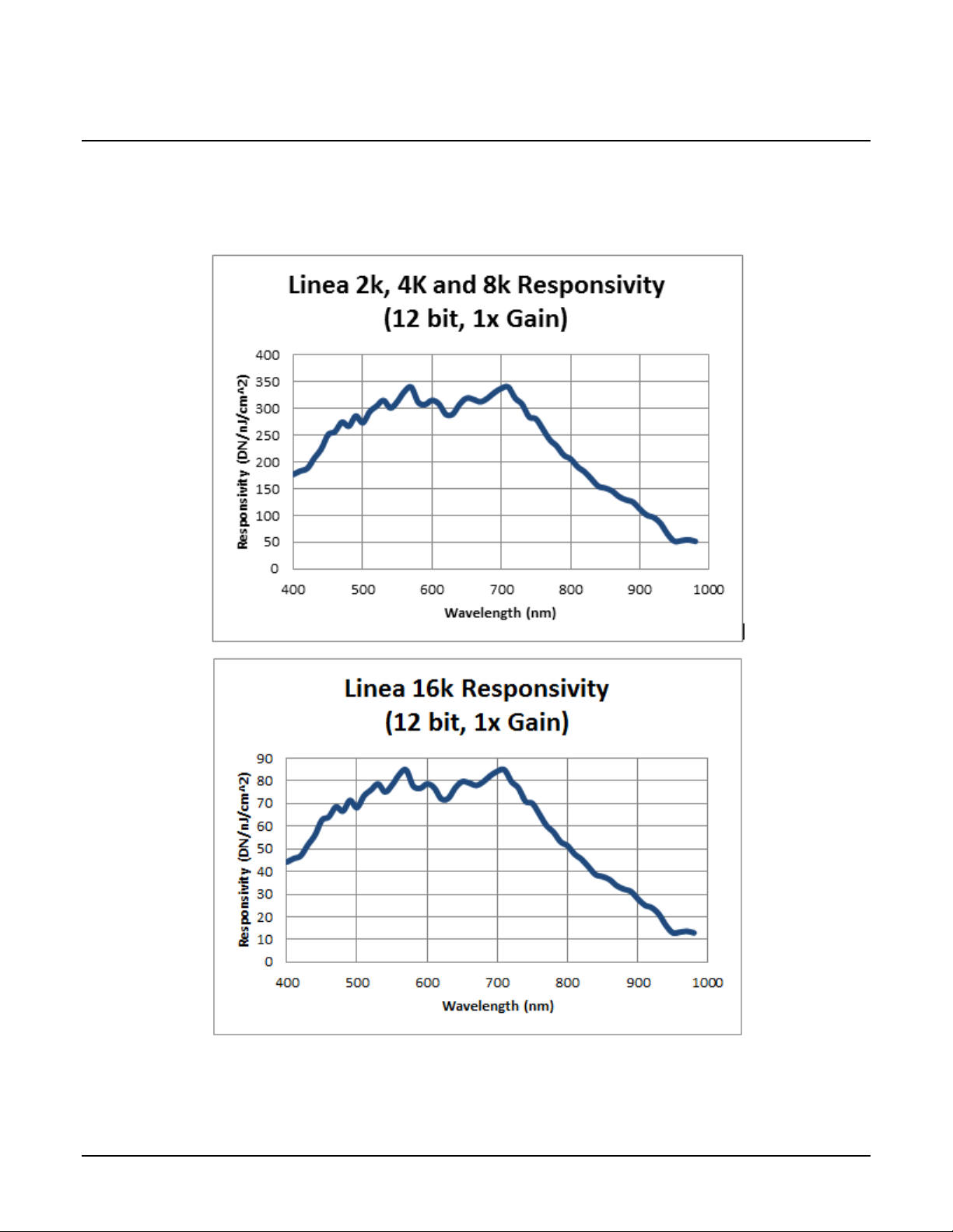
Responsivity
The responsivity graph describes the sensor response to different wavelengths of light (excluding
lens and light source characteristics).
10 • Linea™ CL Series Overview Linea CL Series Camera
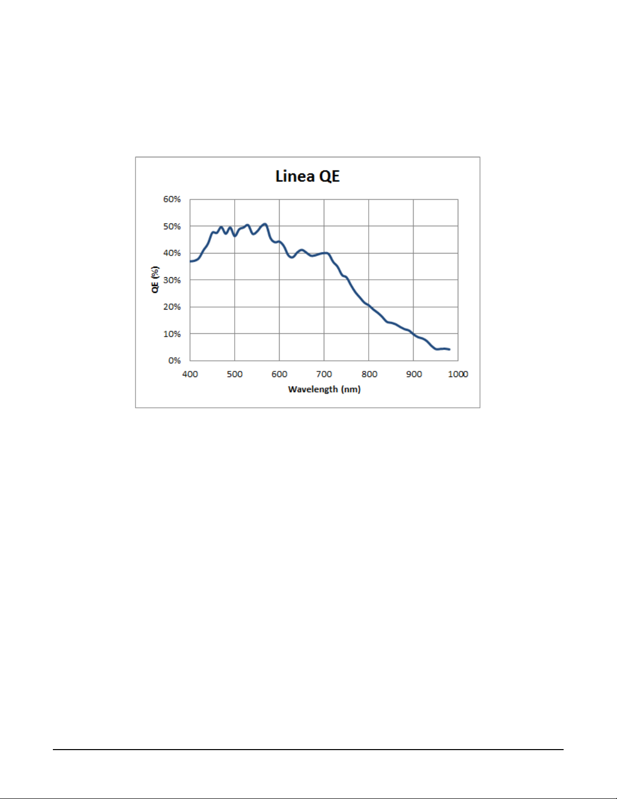
Effective Quantum Efficiency:
The quantum efficiency graph describes the fraction of photons at each wavelength that contribute
charge to the pixel.
Linea CL Series Camera Linea™ CL Series Overview • 11
Linea CL Camera Setup
System Precautions and Cleaning
Precautions
Read these precautions and this manual before using the camera.
Do not open the housing of the camera. The warrant y is voided if the housing is
opened.
• Confirm that the camera’s packaging is undamaged before opening it. If the packaging is
damaged please contact the related logistics pers onnel.
• Keep the camera’s front plate temperature in a range of 0 °C to 65 °C during operation.
• Do not operate the camera in the vicinity of strong electromagnetic fields. In addition, avoid
electrostatic charging, violent vibration, and excess moisture.
• Though this camera supports hot plugging, it is recommended that you power down and
disconnect power to the camera before you add or replace system components.
Cleaning the Device
To clean the device, avoid electrostatic charging by using a dry, clean absorbent cotton cloth
dampened with a small quantity of pure alcohol. Do not use methylated alcohol.
To clean the surface of the camera housing, use a soft, dry cloth. To remove severe stains use a
soft cloth dampened with a small quantity of neutral detergent and then wipe dry. Do not use
volatile solvents such as benzene and thinners, as they can damage the surface finish.
Electrostatic Discharge and the CMOS Sensor
Image sensors and the camera bodies housing are susce ptible to damage from electrostatic
discharge (ESD). Electrostatic charge introduced to the sensor window surface can induce charge
buildup on the underside of the window. If this occurs , the charge normally dissipates within 24
hours and the sensor returns to normal operation.
Recommended System Requirements
To achieve best system performance, the following minimum requirements are recommended:
• High bandwidth frame grabber. For example, Teledyne DALSA Xtium-CL series frame
grabbers: http://www.teledynedalsa.com/imaging/products/fg/#digital-cameralink
• Operating systems: Refer to frame grabber documentation for supported platforms.
.
12 • Linea CL Camera Setup Linea CL Series Camera
Camera Link frame grabber up to receive the standard 8-bit full mode.
computer chassis, before handling the camera hardware..
increased emission or decreased immunity and performance of the camera.
Setup Steps: Overview
Take the following steps in order to setup and run your camera system. They are described briefly
below and in more detail in the sections that follow.
1. Install and Configure Frame Grabber and Software
2. Connect Camera Link and Power Cables
3. Establish communication with the camera
Step 1: Install and Configure Frame Grabber and Software
Teledyne DALSA recommends its Xtium-CL series frame grabbers or equivalent. Follow the
manufacturer’s installation instructio ns.
For additional information on configuring fra me grabbers, see Appendix D: Camera, Frame Grabber
Communication.
Note: By default, Camera Link mode is set to the standard 8-bit full mode which
allows operation of up to 80 kHz (2k, 4k, 8k) or 48 kHz (16K) line rate. Set your
A GenICam™ compliant XML device description file is embedded within the camera firmware
allowing GenICam™ compliant application to know the camera’s capabilities immediately after
connection.
Installing Sapera LT gives you access to the CamExpert GUI, a GenICam™ compliant application.
Sapera LT is available free of charge for download from the Teledyne Dalsa
website.
Step 2: Connect Camera Link and Power Cables
The camera uses two Camera Link SDR26 cables transmitting the Camera Link Base, Medium, or
Full configuration.
• Connect the Camera Link cables from the camera to the frame grabber installed on the
computer.
• Connect a power cable from the camera to a power supply that can provide a constant
voltage from +5 VDC to +24 VDC (2k and 4k) or +12 VDC to +24VDC (8k and 16k).
WARNING! Grounding I nstr uctions
Static electricity can damage electronic components. It’s critical that you discharge
any static electrical charge by touching a grounded surface, such as the metal
Note: the use of cables types and lengths other than those spe cified may result in
For more information on Camera Link connector specifications, see Appendix E: Camera Link
Connector Info rma tion.
Linea CL Series Camera Linea CL Camera Setup • 13
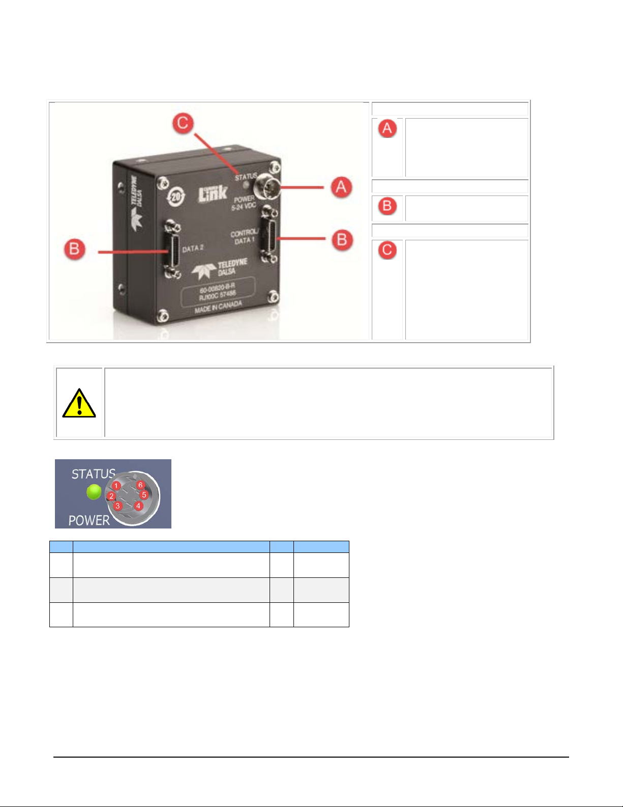
The following figure of the Linea CL back end shows connector and LED locations. See the
Power
Hirose 6-pin
(8k and 16k)
Control & Data
Camera Link 26-pin
SDR26 connectors
Status
Diagnostic LED
Pin
Description
Pin
Description
+12 V to +24 V DC (8K and 16K)
+12 V to +24 V DC (8K and 16K)
+12 V to +24 V DC (8K and 16K)
Mechanical Specifications section for details on the connectors and camera mounting dimensions.
• +5V to +24V DC
(2k and 4k)
• +12V to +24V DC
Power Connector
WARNING! Grounding I nstr uctions
It is extremely important that you apply the appropriate voltages to your camera.
Incorrect voltages may damage the camera. Input voltage re quirements: +5 VDC to
+24 VDC (2k and 4k models), 1 Amp. +12 VDC to +24 VDC (8K and 16K models),
2 Amp. Before connecting power to the camera, test all pow er supplies.
Hirose 6-pin Circular Male (Mating Part: HIROSE HR10A-7P-6S)
1 +5 V to +24 V DC (2K and 4K)
2 +5 V to +24 V DC (2K and 4K)
3 +5 V to +24 V DC (2K and 4K)
4 GND
5 GND
6 GND
14 • Linea CL Camera Setup Linea CL Series Camera
Use high-quality supplies in order to minimize noise.
LED is off
No power or hardware malfunction
Blinking Green
Powering up or ca lib r a ting
Green
Ready
Error. Check the built-in self test (BiST) register for the s p ec ific error
The camera meets all performance specifications using standard switching power supplies,
although well-regulated linear supplies provide optimum performance.
WARNING: When setting up the camera’s power supplies follow these guidelines:
• Apply the appropriate voltages.
• Protect the camera with a 1 amp slow-blow fuse between the power supply
and the camera.
• Do not use the shield on a multi-conductor ca ble fo r ground.
• Keep leads as short as possible in order to reduce voltage drop.
•
Note: If your power supply does not meet these requirements, then the camera
performance specifications are not guaranteed.
Power over Camera Link
The Linea 2k and 4k Camera Link cameras are Power over Camera Link (PoCL) compatible*, but
are not compliant with the full PoCL specification as their operation is dependent on the frame
grabber used. These cameras exceed the 4 W PoCL power specification, but some frame grabbers,
such as the Xtium frame grabber from Teledyne Dalsa, are able to supply sufficient power for the
camera’s operation.
PoCL can be enabled from within CamExpert. Be sure to connect the power supply to the Xtium
frame gabber in the PC.
PoCL power can only be supplied through the Data 1 (base) camera link port.
* The 8K and 16K models do not support PoCL.
Camera Status LED
The Linea CL has one multicolor LED to provide a simple visible indication of camera state. The
table below summarizes the operating states of the camera and the corresponding LED states.
When more than one condit io n is active, the LED indicates the condition with the highest priority.
LED State Definition
Red
Linea CL Series Camera Linea CL Camera Setup • 15
Step 3: Estab lish Commun ication with the Camera
Commands.
The camera is designed to power up with a GenICam-compliant interfa ce. CamExpert
provides an easy-to-use GUI that can be used to set up and operate the camera.
The camera also comes with Teledyne DALSA’s three letter command (TLC) interface
option, which can be accessed using a suitable terminal program such as
HyperTerminal™. If you want to use the TLC interface, refer to Appendix B: ASCII
To establish communication with the camera:
1. Power on the camera
2. Connect to the frame grabber
3. Connect to the camera
Power on the camera
Turn on the camera’s power supply. You may have to wait while the camera readies itself for
operation. The camera must boot fully before it will be recognized by the camera interface
application (for example, CamExpert) — the LED displays steady green once the camera is ready.
Connect to the frame grabber
1. Start Sapera CamExpert (or equivalent Camera Link compliant application) by double
clicking the desktop icon created during the software installation.
2. CamExpert will search for installed Sapera devices. In the Devices list area on the left side,
the connected frame grabber will be shown.
3. Select the frame grabber device by clicking on the name.
Note: The first time you set up the camera you will need to establish a communication
link between the camera and frame grabber.
16 • Linea CL Camera Setup Linea CL Series Camera
Connect to the camera
1. Start a new Sapera CamExpert application (or equivalent Camera Link compliant interface)
by double clicking the desktop icon created during the software installation.
2. In CamExpert, for Teledyne DALSA frame grabbers, the camera appears below the Board
category.
Check LED Status
If the camera is operating correctly at this point, the diagnostic LED is steady green.
Software Interface
All the camera features can be controlled through the CamExpert interface. For example, under the
Camera Control menu in the camera window you can cont rol the line rate and exposure times.
Operate the Camera
At this point you will be ready to start operating the camera to acquire images, set camera
functions, and save settings.
Linea CL Series Camera Linea CL Camera Setup • 17
Using CamExpert with Linea CL Cameras
The Sapera CamExpert tool is the interfacing tool for GenCP compliant Camera Link cameras, and
is supported by the Sapera library and hardware. When used with a Linea CL camera, CamExpert
allows a user to test most of the operating modes. Additionally CamExpert saves the Linea CL user
settings configuration to the c amera or saves multiple configura tions as individual camera
parameter files on the host system (*.ccf).
An important component of CamEx pert is its liv e acquisition display win dow which allows
immed iate verification of timin g or contro l parameters w ithout the need to run a separate
acquisition program.
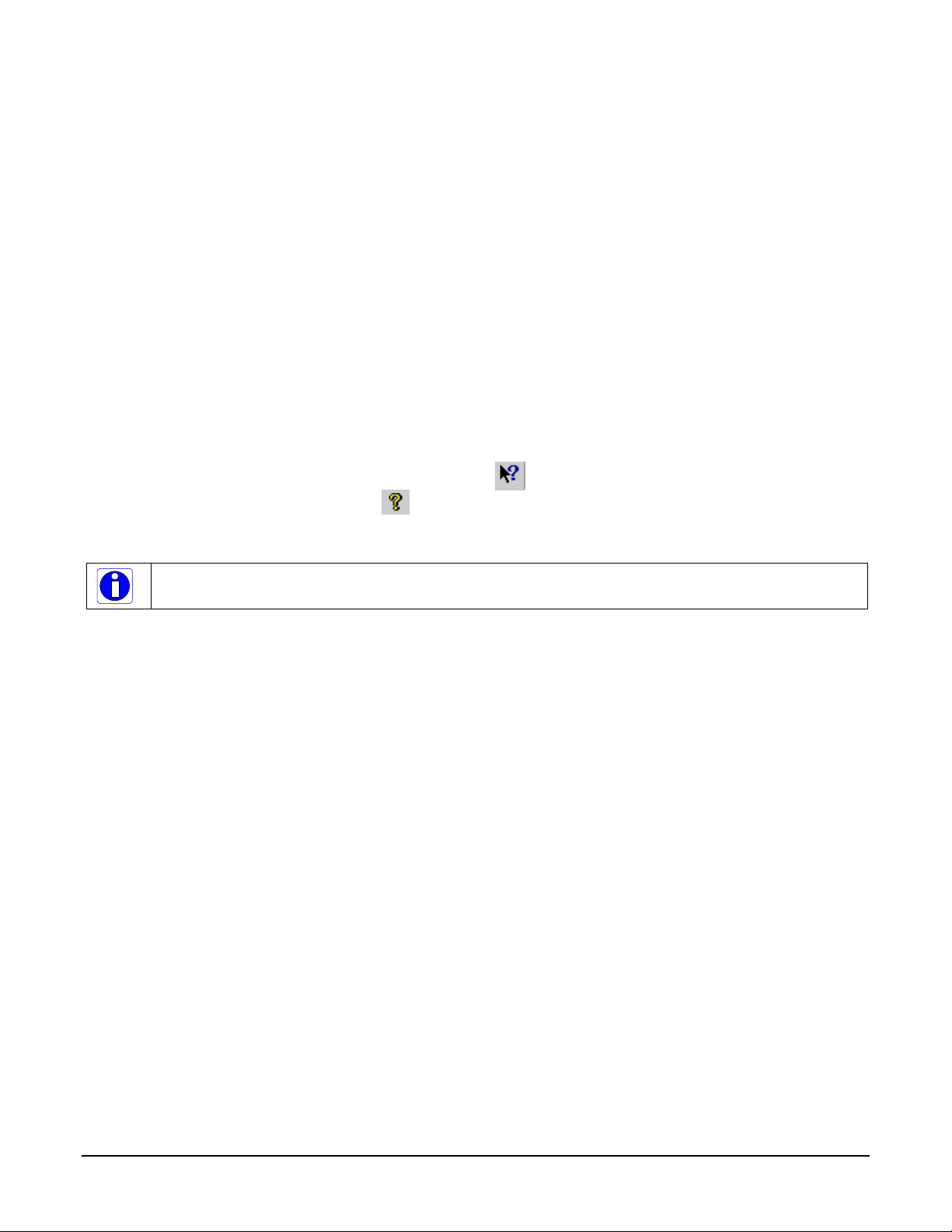
Click on any parameter and a short description is displayed below the Category pane. The same
conte xt sensitive help is available by clicking on the button then click on a camera
configuration parameter. Click on the button to open the help file for more descriptive
information on CamExpert.
Note: The examples shown may not entirely reflect the features an d pa ra m eter s a vailable from
the camera model and camera mode used in your applica tion.
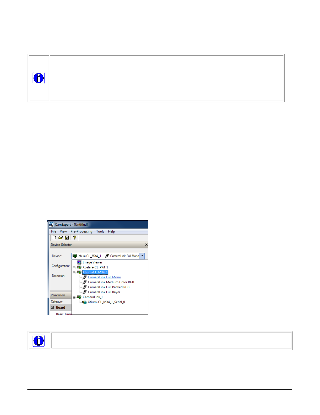
CamExpert Panes
The various areas of the CamExpert tool are described in the figure below. Device Categories and
Parameter features are displayed as per the device’s XML description file. The number of
parameters shown is dependent on the View mode selected (Beginner, Expert, Guru – see
description below).
18 • Using CamExpert with Linea CL Cameras Linea CL Series Camera
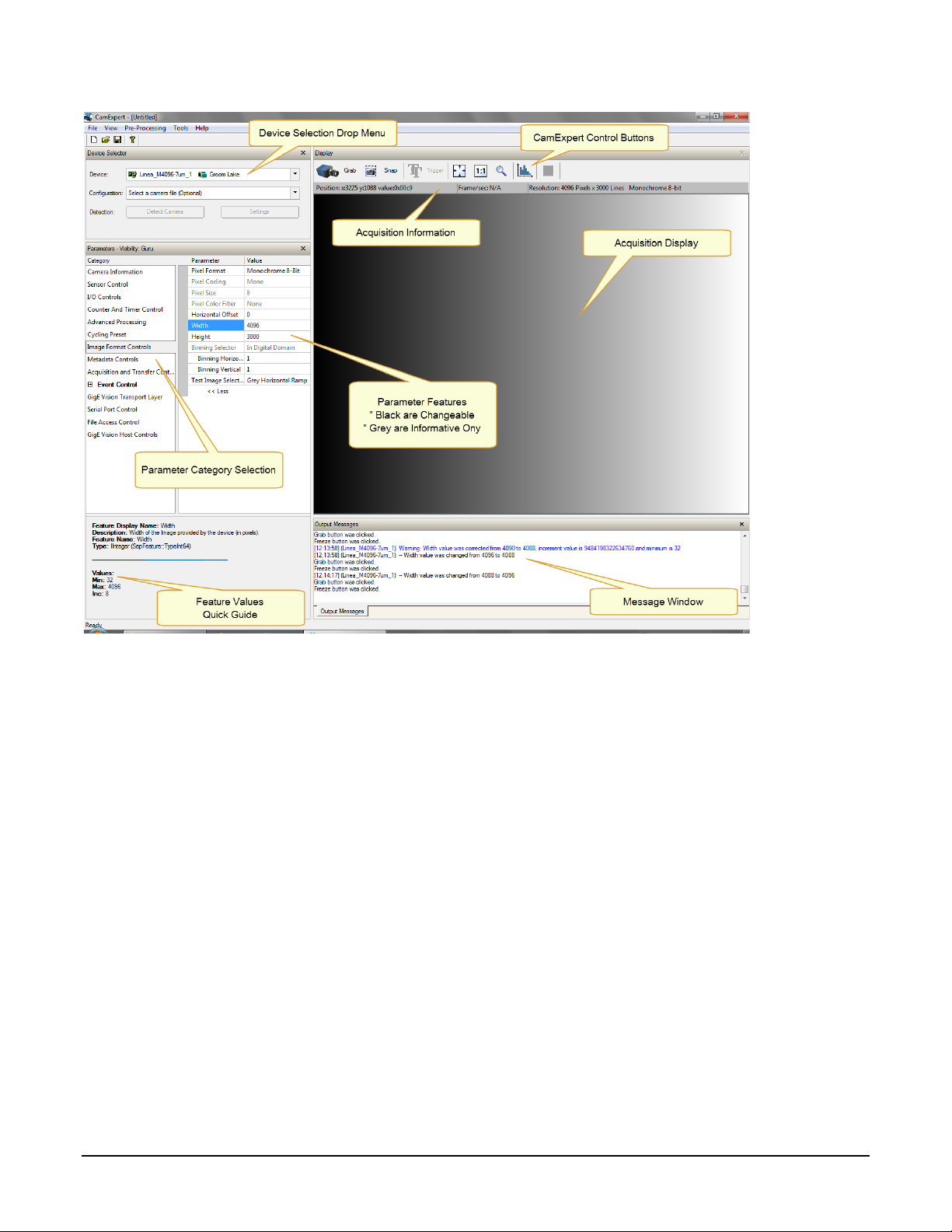
• Device Selector pane: View and select from any installed Sapera acquisition device. After a
device is selected, CamExpert will only present parameters applicable to that device. Optionally
select a camera file included with the Sapera installation or saved by the user.
• Parameters pane: Allows viewing or changing all acquisition parameters supported by the
acquisition device. CamExpert displays parameters only if those parameters are supported by
the installed device. This avoids confusion by eliminating parameter choices when they do not
apply to the hardware in use.
• Display pane: Provides a live or single frame acquisition display. Frame buffer parameters are
shown in an information b ar above the image window.
• Control Butto ns: The Display pane includes CamExpert control buttons. These are:
Linea CL Series Camera Using CamExpert with Linea CL Cameras • 19
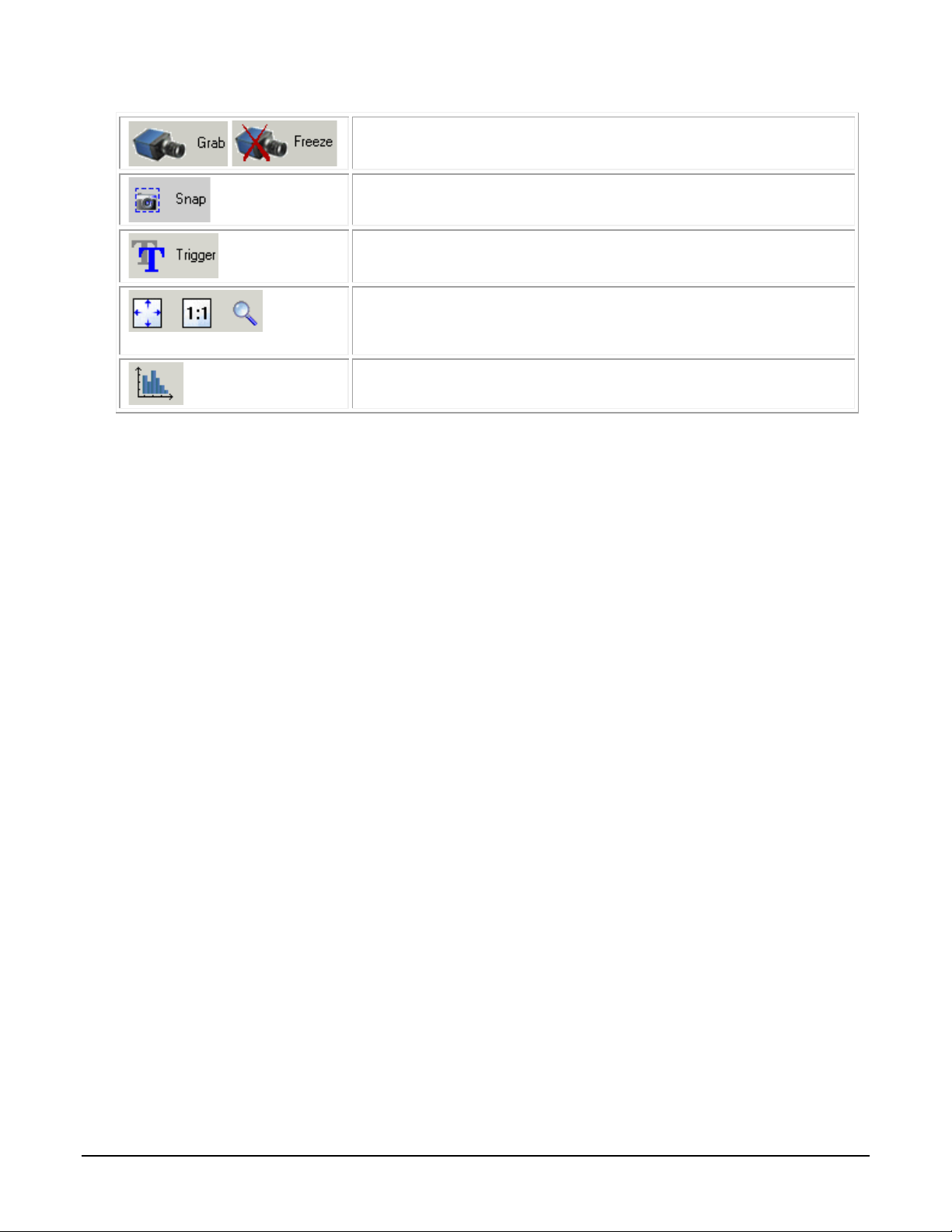
Acquisition control button:
Click once to start live grab, click again to stop.
Single frame grab:
Click to acquire one frame from device.
Software trigger button:
With the I/O control parameters set to Trigger Enable d / Softwa r e Tr igg e r
type, click to send a single software trigger comm and .
CamExpert display contro l s:
(these do not modify the frame buffer data)
Stretch (or shrink) image to fit, set image display to original size, or zoom
the image to any size and ratio. This does not affect the acquisition.
Histogram / Profile tool:
Select to view a histogram or line/column prof i le dur ing liv e acq uis ition.
• Output pane: Displays messages from CamExpert.
CamExpert View Parameters O p tion
All camera features have a Visibility attribute which defines its requirement or complexity. The
states vary from Beginner (features required for basic operation of the device) to Guru (optional
features required only for complex operations).
CamExpert presents camera features based on their visibility attribute. CamExpert provides quick
Visibility level selection via controls below each Category Parameter list [ << Less More >> ]. The
user can also choose the Visibility level from the View ∙ Parameters Options menu.
Creating a Camera Configuration File in the Host
• When using the Teledyne DALSA Sapera SDK – the CCF is created automatically via a save.
• When using a 3
automatic. Simply follow the 3
• If the SDK is based on GenAPI 2.3 or lower, the user must call the command
DeviceFeaturePersistenceStart before using the SDK Save Came ra method and the command
DeviceFeaturePersistenceEnd at the end of the save function.
rd
party SDK application, if that SDK supports GenAPI 2.4, then the process is
rd
party Save Camera method as instructed.
20 • Using CamExpert with Linea CL Cameras Linea CL Series Camera

Camera Operation
The following sections describe typical operations performed with the camera. The descriptions rely
on the feature-based Camera Link GenCP protocol, using the Sapera CamExpert application. If you
are using a different application, the display configuration will differ but the category, parameter
(feature) names and possible values remain the same. References to related ASCII commands are
provided.
Factory Settings
The camera has been calibrated and configured at the factory to be ready for operation when first
powered up. The camera ships and powers up for the first time with the following factory settings:
• Camera Link Full, 8 bit pixels
• Internal trigger, line rate 10 kHz
• Internal exposure control, exposure time 50 µs
• 1x horizontal an d ver tical binning
• Offset 0, Gain 1x (lowest value)
• Flat field calibration is not active as this feature is dependent on your light source and lens.
Linea CL Series Camera Camera Operation • 21

Typical Setup and Evaluation
Optical Configuration
Typically, the first thing you want to do is to evaluate the camera’s image quality under operating
conditions similar to those that you are likely to use in your application. To do this, take the
following steps:
• The illumination, lens magnification, and focus should be set up as per you applicat ion .
• Getting the magnification right is best accomplished by setting the object-to-sensor
distance. Use the formula lens focal length x (2 + 1/magnification + magnification) to
calculate this distance. Magnificat ion equ als the sensor pixel size (7.04 µm or 3.52 µm ) /
(your object pixel size in µm).
• The approximate position of the sensor is at the first groove on the side of the camera case
from the front face of the camera.
Camera Timing & Control
It is easiest and quickest to evaluate the camera using the internal timing setups for line rate and
exposure time. The camera starts up in the default configuration of camera link full, 10 kHz line
rate and 50 µsec exposure time.
• If this line rate is too slow fo r your application, you will get a compressed image in the scan
direction. To increase the line rate, use the Internal Line Rate parameter in the Camera
Control category.
• Adjust the exposure time; refer to the Exposure Controls section.
• Set your camera direction: refer to the Pixel Readout Direction (Mirroring Mode) section.
Acquiring an Image
You can now begin imaging . Unless you have an application employing lots of light, the image is
likely to be too dark.
• Use the system gain to adjust the camera output to achieve the desired response. The
system gain range is from 1x to 10x. Refer to the Gain and Black Level (Offset) section.
• Once you have a suitable response, you can now focus the lens.
• The image may be darker at the edges due to lens vignetting, but this will be improved once
the camera is calibrated.
• Calibration is performed using a white reference where your object is normally located.
Refer to the Calibrating the Camera section. When calibrated, you should see an image from
the camera that is flat field corrected with the lens at the target level you set.
You are now ready to evaluate the image quality of the Linea camera under your operating
conditions.
22 • Camera Operation Linea CL Series Camera
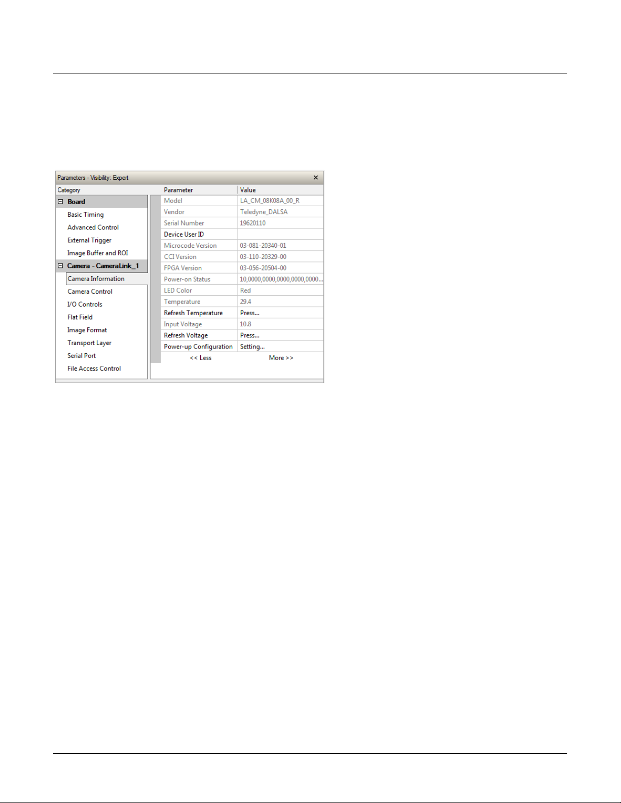
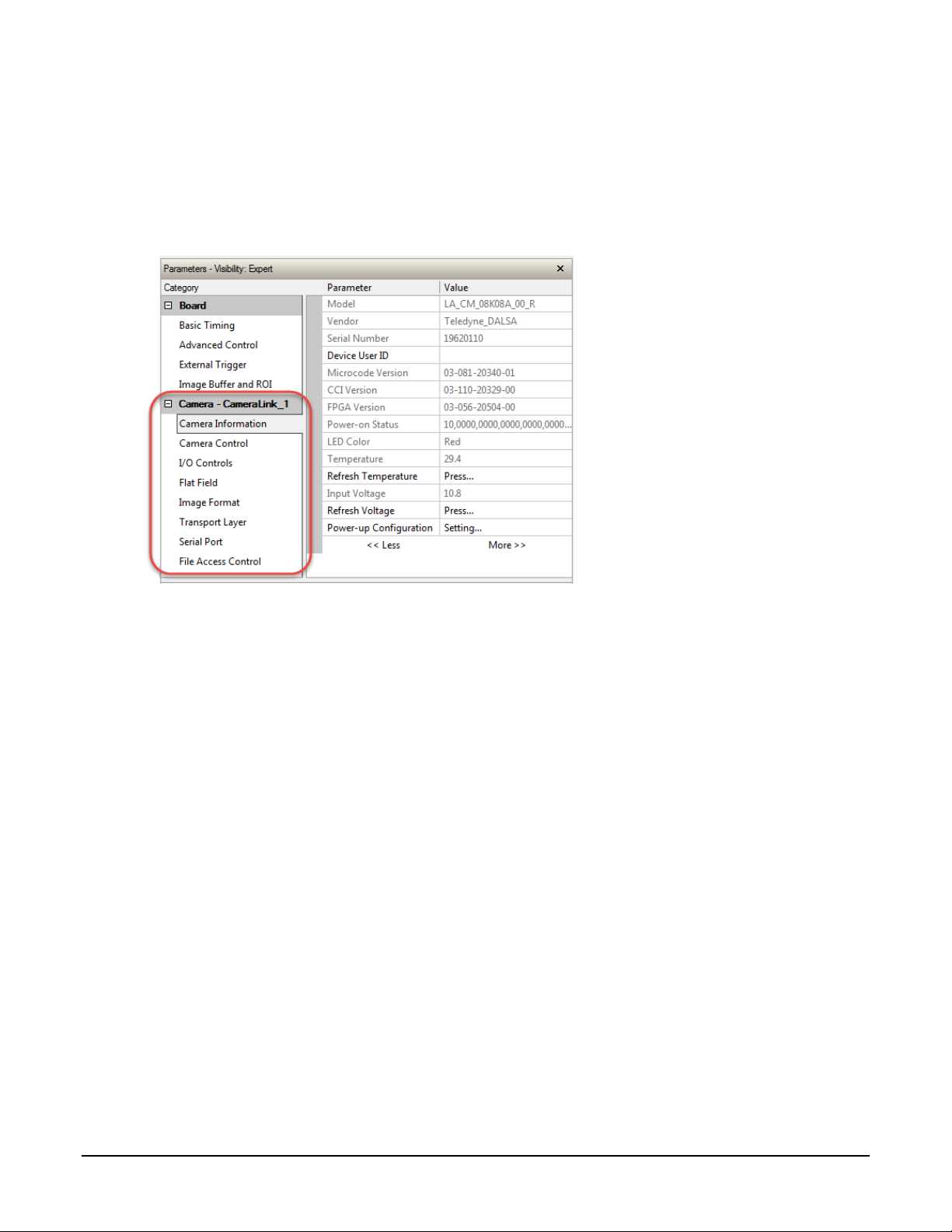
Check Camera and Sensor Information
Camera and sensor information can be retrieved via a controlling application—for example, the
CamExpert GUI shown in the following examples. Parameters such as camera model, firmware
version, sensor characteristics, and so forth, are read to uniquely identify the connected device.
The Camera Information category groups these parameters.
Verify Temperature and Voltage
To determine the voltage and temperature at the camera, use the Refresh Voltage and Refresh
Temperature features.
The temperature returned is the internal temperature in degrees Celsius. For proper operation this
value should not exceed 80 °C. If the camera exceeds the designated temperature it will stop
imaging and the LED will turn red. After you have diagnosed and remedied the issue use the
Restart Camera function.
The parameters used to select, load and save user sets are grouped together under the Camera
Information category. There are 8 user sets available and one factory set.
Linea CL Series Camera Camera Operation • 23
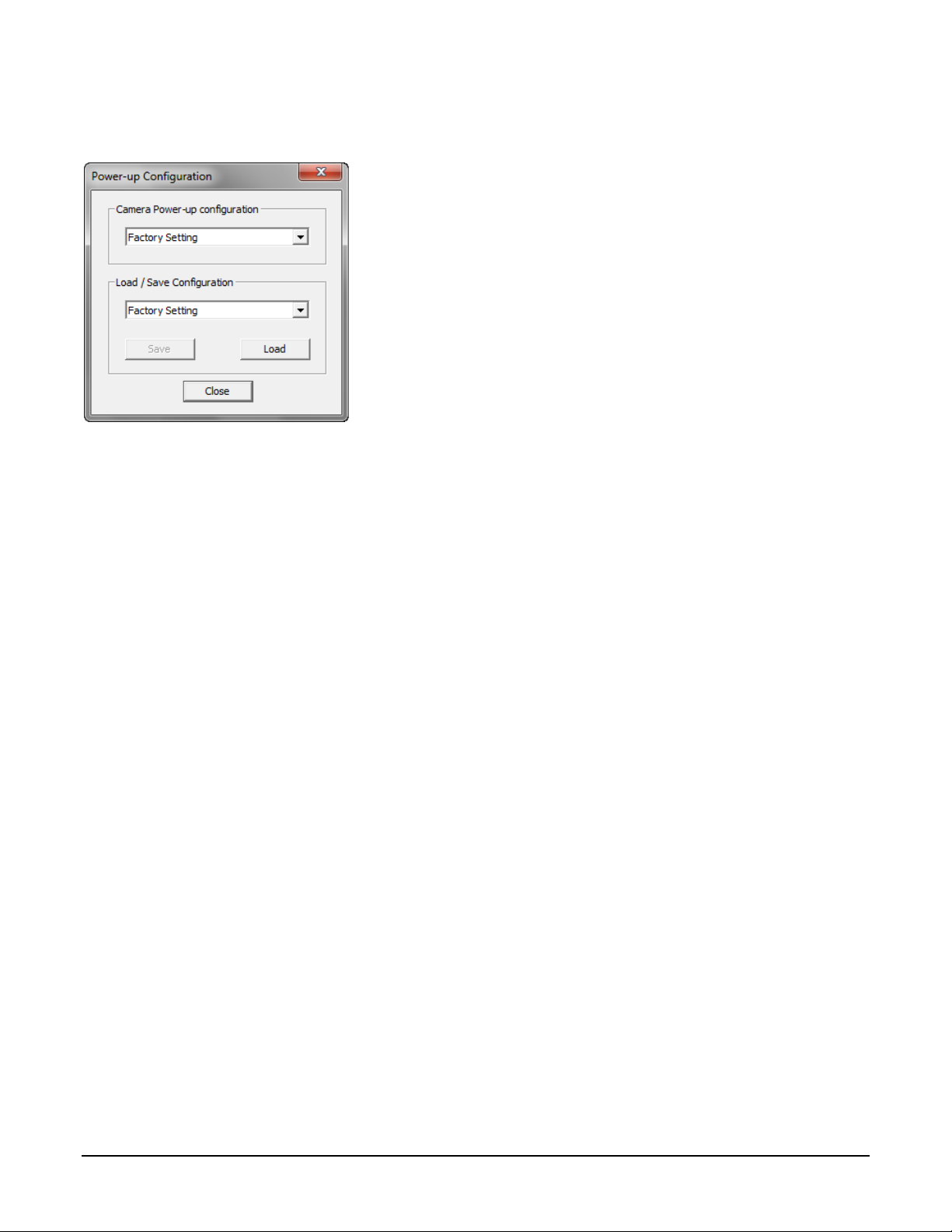
Camera Config uration Selection Dialog
CamExpert provides a dialog box which combines the features to select the camera power up state
and for the user to save or load a camera state from Linea CL memory.
Camera Power-up Configuration
Either the Factory or one of the User Settings can be used as the default setting and is the set
loaded when the camera is reset of powered up.
The first drop list selects the camera configuration state to load on power-up (see feature
UserSetDefaultSelector). The user chooses from one factory data set or one of 8 possible user
saved states.
User Set Configuration Mana g em en t
The user setting is the saved set of camera configurations that you can customize, resave, and
restore. By default the user settings are shipped with the same settings as the factory set.
The second drop list allows the user to change the camera configuration anytime after a power-up
(see feature UserSetSelector). To reset the camera to the factory configuration, select Factory
Setting and click Load. To save a current camera configuration, select from User Set 1 through
User Set 8, and click Save. Select a saved user set and click Load to restore a saved configuration.
Active Settings for Current Operation
The active setting for the current operation is the set of configurations that are active while the
camera is currently running, including all unsaved changes you have made to the settings before
saving them.
These active settings are stored in the camera’s volatile memory and will be lost and cannot be
restored if the camera resets, is powered down, or loses power.
To save these settings for reuse the next time you power up or reset the camera, or to protect
against losing them in the case of power loss, you must save the current settings. Once saved, the
current settings become the selected User Set.
24 • Camera Operation Linea CL Series Camera
Related ASCII Commands
usd
user set default
usl
user set load
uss
user set save
measurement can be used to set the applied voltage to the camera.
User Setting
The command User Set Save saves the current settings to non-volatile memory as a Use r Set.
The camera automatically restores the last saved user settings when it powers up.
To restore the last saved user settings, select the User Set parameter you want to restore and
then select the User Set Load parameter.
Factory Settings
The factory setting is the camera settings that were shipped with the camera and which loaded
during the camera’s first power-up. To load or restore the original factory settings, at any time,
select the Factory Setting parameter and then select the User Set Load parameter.
Note: By default, the user settings are set to the factory settings.
section).
Note: The voltage displayed is the camera’s input voltage. The voltage measurement
feature of the camera provides results within 1% of the actual voltage. The
Linea CL Series Camera Camera Operation • 25
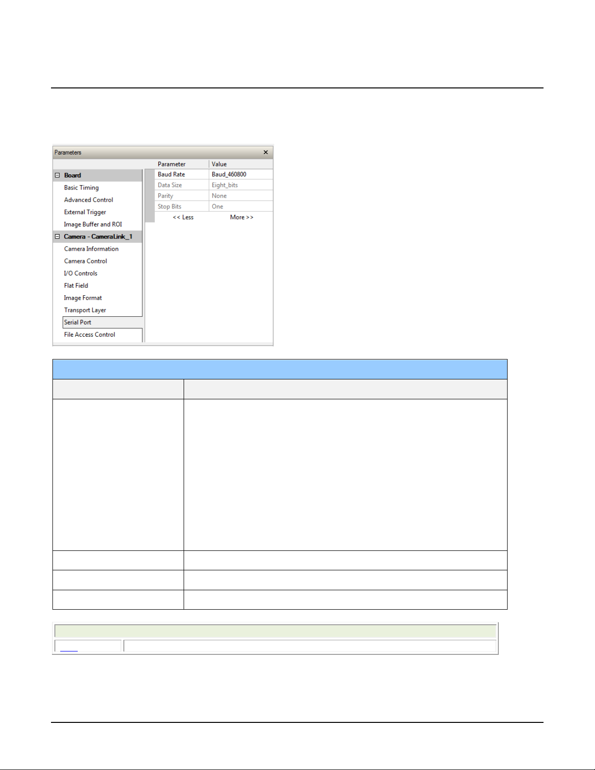
Set Baud Rate
Serial Port
Parameter
Description
achieve these baud rates.
Related ASCII Commands
sbr
set baud rate
The baud rate sets the speed (in bits per second—bps) of the serial communication port and is
available as part of the Serial Port category.
Baud Rate Sets the baud rate used by the camera’ s s er ia l port. Possible values
are:
• 9600 (factory default)
• 19200
• 57600
• 115200
• 230400*
• 460800*
Note: During connection, by default, CamExpert automa tic ally sets the
camera to maximum allowable baud.
*A Teledyne DALSA PX4 or equivalent frame gra bber is r equired to
Data Size 8 (read-only)
Parity None (read-only)
Number of Stop Bits 1 (read-only)
26 • Camera Operation Linea CL Series Camera
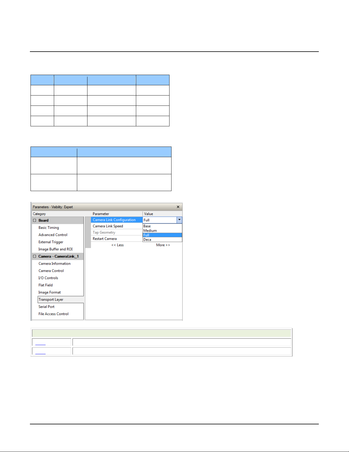
Name
Taps
Bits Per Pixel
Cables
Base
2
8, 12
1
Medium
4
8, 12
2
Full 8 8
2
Deca*
10 8 2
Camera Model
Available Camera Link Speeds
2K, 4K, and 8K
77 MHz
50 MHz
16K
85 MHz
62 MHz
Related ASCII Commands
clm
camera link mode
spf
set pixel format
Camera Link Configuration
The following Camera Link configurations are available:
*8k and 16k models only
Available Camera Link speeds are model dependent:
The Camera Link Configuration feature is available in the camera’s Transport Layer category:
Linea CL Series Camera Camera Operation • 27
 Loading...