

Page 1

OPERATING INSTRUCTIONS FOR
Model 3500 Series
Laser Gas Analysis System
P/N MXXXX
ECO:
DANGER
Toxic gases and or flammable liquids may be present in this monitoring system.
Personal protective equipment may be required when servicing this instrument.
Hazardous voltages exist on certain components internally which may persist
for a time even after the power is turned off and disconnected.
Only authorized personnel should conduct maintenance and/or servicing.
Before conducting any maintenance or servicing, consult with authorized
supervisor/manager.
Copyright © 2005 Teledyne Analytical Instruments
Teledyne Analytical Instruments
Page 2

Model 3500
All Rights Reserved. No part of this manual may be reproduced, transmitted, transcribed,
stored in a retrieval system, or translated into any other language or computer language in
whole or in part, in any form or by any means, whether it be electronic, mechanical,
magnetic, optical, manual, or otherwise, without the prior written consent of Teledyne
Analytical Instruments, 16830 Chestnut Street, City of Industry, CA 91749-1580.
Warranty
This equipment is sold subject to the mutual agreement that it is warranted by us free from
defects of material and of construction, and that our liability shall be limited to replacing or
repairing at our factory (without charge, except for transportation), or at customer plant at our
option, any material or construction in which defects become apparent within one year from
the date of shipment, except in cases where quotations or acknowledgements provide for a
shorter period. Components manufactured by others bear the warranty of their manufacturer.
This warranty does not cover defects caused by wear, accident, misuse, neglect or repairs
other than those performed by Teledyne or an authorized service center. We assume no
liability for direct or indirect damages of any kind and the purchaser by the acceptance of the
equipment will assume all liability for any damage which may result from its use or misuse.
We reserve the right to employ any suitable material in the manufacture of our apparatus,
and to make any alterations in the dimensions, shape or weight of any parts, in so far as
such alterations do not adversely affect our warranty.
Important Notice
This instrument provides measurement readings to its user, and serves as a tool by which
valuable data can be gathered. The information provided by the instrument may assist the user
in eliminating potential hazards caused by his process; however, it is essential that all
personnel involved in the use of the instrument or its interface, with the process being
measured, be properly trained in the process itself, as well as all instrumentation related to it.
The safety of personnel is ultimately the responsibility of those who control process
conditions. While this instrument may be able to provide early warning of imminent
danger, it has no control over process conditions, and it can be misused. In particular, any
alarm or control systems installed must be tested and understood, both as to how they
operate and as to how they can be defeated. Any safeguards required such as locks, labels,
or redundancy, must be provided by the user or specifically requested of Teledyne at the
time the order is placed.
Therefore, the purchaser must be aware of the hazardous process conditions. The purchaser
is responsible for the training of personnel, for providing hazard warning methods and
instrumentation per the appropriate standards, and for ensuring that hazard warning devices
and instrumentation are maintained and operated properly.
Teledyne Analytical Instruments, the manufacturer of this instrument, cannot accept
responsibility for conditions beyond its knowledge and control. No statement expressed or
implied by this document or any information disseminated by the manufacturer or its
agents, is to be construed as a warranty of adequate safety control under the user’s process
conditions.
Teledyne Analytical Instruments ii
Page 3

Laser Gas Analyzer
Specific Model Information
Instrument Serial Number: _______________________
Instrument Range: _______________
Calibrated for: _______________
Background Gas: _______________
Zero Gas: _______________
Span Gas: _______________
Teledyne Analytical Instruments iii
Page 4
Model 3500
Safety Messages
Your safety and the safety of others is very important. We have
provided many important safety messages in this manual. Please read
these messages carefully.
A safety message alerts you to potential hazards that could hurt you
or others. Each safety message is associated with a safety alert symbol.
These symbols are found in the manual and inside the instrument. The
definition of these symbols is described below:
GENERAL WARNING/CAUTION: Refer to the instructions
for details on the specific danger. These cautions warn of
specific procedures which if not followed could cause bodily
Injury and/or damage the instrument.
CAUTION: HOT SURFACE WARNING: This warning is
specific to heated components within the instrument. Failure
to heed the warning could result in serious burns to skin and
underlying tissue.
WARNING: ELECTRICAL SHOCK HAZARD: Dangerous
voltages appear within this instrument. This warning is
specific to an electrical hazard existing at or nearby the
component or procedure under discussion. Failure to heed this
warning could result in injury and/or death from
electrocution.
Technician Symbol: All operations marked with this symbol
are to be performed by qualified maintenance personnel only.
No
Symbol
CAUTION: THE ANALYZER SHOULD ONLY BE USED FOR THE
NOTE: Additional information and comments regarding a
specific component or procedure are highlighted in the form
of a note.
PURPOSE AND IN THE MANNER DESCRIBED IN
THIS MANUAL.
Teledyne Analytical Instruments iv
Page 5

Laser Gas Analyzer
IF YOU USE THE ANALYZER IN A MANNER OTHER
THAN THAT FOR WHICH IT WAS INTENDED,
UNPREDICTABLE BEHAVIOR COULD RESULT
POSSIBLY ACCOMPANIED WITH HAZARDOUS
CONSEQUENCES.
This manual provides information designed to guide you through
the installation, calibration operation and maintenance of your new
analyzer. Please read this manual and keep it available.
Occasionally, some instruments are customized for a particular
application or features and/or options added per customer requests.
Please check the front of this manual for any additional information in
the form of an Addendum which discusses specific information,
procedures, cautions and warnings that may be peculiar to your
instrument.
Manuals do get lost. Additional manuals can be obtained from
Teledyne at the address given in the Appendix. Some of our manuals are
available in electronic form via the internet. Please visit our website at:
www.teledyne-ai.com.
Teledyne Analytical Instruments v
Page 6

Model 3500
Table of Contents
Peter.Adam@linde-gas.com
List of Figures ..............................................................................ix
List of Tables................................................................................xi
Introduction................................................................................... 1
1.1 Overview 1
1.2 Models Available in the 3500 Series 1
1.2.1 Available Options 1
1.2 Classification of LGA-2000 Laser Gas Analysis
Systems 2
1.2 Typical Applications 3
1.3 Features 4
1.4 System Components 4
Operational Theory.......................................................................7
2.1 Introduction 7
2.2 Principles of Operation 8
2.3 Software 10
Installation................................................................................... 11
3.1 Unpacking the Instrument 11
3.2 Installation Preparation 11
3.2.1 Installation and Adjustment Tools 11
3.2.2 Choosing Installation Spot 13
3.3 Analysis Section Installation 13
3.3.1 Welding Flanges 13
3.3.2 Installing Instrument Flanges 14
3.3.3 Checking Offset Using the Laser Pen and Target 15
3.3.3.1 Checking the Laser Pen for Alignment 15
3.3.3.2 Adjusting the Coaxial Offset of the Instrument
Flanges 16
Teledyne Analytical Instruments vi
Page 7

Laser Gas Analyzer
3.3.4 Installing the Transmitter Unit and the Receiver Unit 17
3.4 Central Processing Unit Installation 17
3.5 Purge System Installation 18
3.6 Electric Wiring and Connection 19
3.7 Optimize of the Optical Transmission Alignment 22
Operation .....................................................................................23
4.1 Front Panel 23
4.2 System Mode 24
4.2.1 Start-up Mode 24
4.2.2 Normal Mode 26
4.2.3 Error Mode 27
4.3 System Menu 27
4.3.1 MainMenu 28
4.3.2 Display 33
4.3.3 System 38
4.3.3.1 System Parameter Input Method 39
4.3.3.2 System sub menus 41
4.3.4 Cali. 46
4.3.4.1 Adjust Zero: 47
4.3.4.2 Cali. Co: 48
4.3.4.3 Backup 51
4.3.4.4 Restore 51
4.3.5 Com 51
4.3.6 Alarm 52
4.3.7 Additional Menus 57
4.3.7.1 Message Code: 57
4.3.7.2 Password Input: 58
4.3.7.3 Error Protection Menu: 58
Alarm Messages..........................................................................61
5.1 Relay Alarm 61
5.2 4-20mA Analog Output 61
5.3 LCD Alarm Message Display 62
Teledyne Analytical Instruments vii
Page 8

Model 3500
Maintenance and Calibration .....................................................67
6.1 Maintenance 67
6.1.1 Adjusting the Purge Gas Flow 67
6.1.2 Clean the Optical Parts 68
6.1.3 Optimize the Optical Transmission Alignment 70
6.2. Calibration 70
6.2.1 Calibration Procedure 72
6.2.2 Calibration Software 74
Extended Communication Functions........................................ 75
Appendix...................................................................................... 77
Specifications 77
Recommended Spare Parts List 79
Reference Drawings 79
Index............................................................................................. 81
Teledyne Analytical Instruments viii
Page 9

Laser Gas Analyzer
List of Figures and Screens
Figure 1-1 Control Section...............................................................5
Figure 1-2: Model 2500 Laser Gas Analysis System.......................6
Figure 2-1: System Diagram for the Model 3500 Series Analyzers.7
Figure 2.2 Schematic of “Single line” Spectroscopy........................9
Figure 3-1: General Layout of the Model 3500 Series Analyzer....12
Figure 3.2: Allowed offset for welded flanges................................14
Figure 3-3: Instrument Flange.......................................................15
Figure 3.4 Adjusting the Instrument Flanges with Laser Pen and
Target.....................................................................................16
Figure 3.5 Dimension of the Central Processing Unit (in mm).......17
Figure 3.6 Typical Purging System for the Model 3500.................19
Figure 3.7 Electric Connection Ports on the Central Processing
Unit for Non-fiber Optic Analysis Systems..............................20
Figure 3.8: Electric Connection Ports on the Central Processing
Unit for Analysis Systems Using Fiber Optic Pigtail ...............21
Figure 4-1: Model 3500 Series Front Panel...................................23
Figure 4.2 System Start-up Screen...............................................25
Figure 4.3 System Init Screen.......................................................25
Figure 4.5: System Menu Structure...............................................28
Figure 4-6: MainMenu—Graphic...................................................29
Figure 4.7 Numerical Value Mode of the MainMenu .....................30
Figure 4.8 Display menu................................................................33
Figure 4.9 Display Mode Options..................................................34
Figure 4.10 Unit Menu...................................................................34
Figure 4.11 Set Con. Unit menu....................................................35
Teledyne Analytical Instruments ix
Page 10

Model 3500
Figure 4.12 Pop-up Window for Language Selection....................36
Figure 4.13 TimeDate Menu..........................................................36
Figure 4.14 Admin. Menu.............................................................. 37
Figure 4.15 System main menu ....................................................38
Figure 4.16 Set Optical Path Length............................................. 40
Figure 4.22 Schematic showing purging gas channel...................45
Figure 4.35 Time sequence of the alarm relay automatic
restoration..............................................................................56
Figure 6.1 Schematic of the calibration setup ...............................70
Figure 6.2 Removing the Transmitter Receiver Units.................... 72
Figure 7.1 Schematic for Networked Multiple-point Remote
Measurement on Model 3500 Systems.................................. 75
Teledyne Analytical Instruments x
Page 11

Laser Gas Analyzer
List of Tables
Table 1-1 Instrument Designation for Selected Options..................2
Table 1-2: Typical Gas Analysis and Range....................................3
Table 3.1 Electric connections & definitions of Input, Output
Signals of Central Processing Unit.........................................21
Table 5.1 Relays and output status for Various Operation Modes 62
Table 5.2: LCD Display Alarm Messages......................................63
Teledyne Analytical Instruments xi
Page 12
Model 3500
DANGER
COMBUSTIBLE GAS USAGE
Depending on the selected options, some instruments may
be used in hazardous environments. This may involve the
measurement or monitoring of flammable or explosive
gases. It is the end user’s responsibility to ensure that all
safety related features of this instrument are properly
functioning and that the operator is fully trained in the
operation of the system as well as procedures for handling
the gases employed.
WARNING
Some instruments are approved as an intrinsically safe gas
analyzers for usage in a category (ia) Group IIC hazardous
area. This approval only to the equipment specified installed
in accordance with the information contained within this
manual. It is the customer's responsibility to ensure safety
especially when combustible gases are being analyzed since
the potential of gas leaks always exist.
The customer should ensure that the principles of operating
of this equipment is well understood by the user and that the
instrument as well as any approved support equipment is
properly installed. Misuse of this product in any manner,
tampering with its components, or unauthorized substitution
of any component may adversely affect the certification and
the safety of this instrument.
Since the use of this instrument is beyond the control of
Teledyne, no responsibility by Teledyne, its affiliates, and
agents for damage or injury from misuse or neglect of this
equipment is implied or assumed.
Teledyne Analytical Instruments xii
Page 13
Laser Gas Analyzer
DANGER
LASER RADIATION
This instrument produces laser radiation which can cause
damage to human tissue especially the eyes. Do not look at
the laser beam nor open any chamber or device without first
powering off the instrument.
WARNING: THE WAVELENGTH OF THE LASER BEAM INSIDE
THE MODEL 3500 SERIES OF ANALYZERS IS IN THE
RANGE OF 0.7 ~ 2µM. IT IS INFRARED AND
INVISIBLE. DO NOT LOOK DIRECTLY OR WITH
OPTICAL INSTRUMENT AT THE DIRECTION OF THE
LASER RADIATION
HAZARD
Teledyne Analytical Instruments xiii
Page 14

Model 3500
Teledyne Analytical Instruments xiv
Page 15

Laser Gas Analyzer Introduction
Introduction
1.1 Overview
The Model 3500 series Laser Gas Analysis System comprises a
range of instruments based on the features and configuration chosen at
the time of purchase. The system uses laser spectroscopy to accurately
measure and monitor the composition of a single or multiple gas species
in a gas mixture. It is especially useful for in-situ measurements and is
designed for online processes analysis. Options are available for
applications involving hazardous environments.
This manual describes the installation, calibration, operation, and
maintenance of the LGA system. The principles of instrument operation
are detailed in Section 2.
1.2 Models Available in the 3500 Series
The Model 3500 series of instruments are classified depending on
the options specified at the time of purchase. The specific model number
assigned is described below following a brief description of the available
options to choose from.
1.2.1 AVAILABLE OPTIONS
The standard Model 3500 LGA System is configured for single gas
species detection in a gas mixture using a flange mounted laser transmitter
and receiver for online in-situ measurements in non-hazardous environments.
The following list indicates available options for the Model 3500
series of analyzers (see also Table 1-1):
• Two gas detection in a gas mixture
• Fiber optic connection to remove sensitive laser and electronics
from monitoring environment
• Explosion-proof housing
• Intrinsically safe instrumentation
Teledyne Analytical Instruments 1
Page 16

Introduction Model 3500
Table 1-1 Instrument Designation for Selected Options
3500C
3500P
3500CS
3500PS
3500-2C
3500-2P
3500-2CS
3500-2PS
3500F
3500I
3500FS
3500IS
3500-2F
3500-2I
3500-2FS
3500-2IS
Number
of Gas
Species
One Two
√
√
√
√
√ √
√ √
√
√
√
√
√
√
√ √
√ √
√
√
Detection Optical
Signal
Transmission
By-
In
Pass
Situ
√
√
√
√
√
√
√
√
√ √
√ √
√ √
√ √
Optical
Fiber
√
√
√
√
Non-
optical
Fiber
√ √
√
√ √
√
√ √
√
√ √
√
General
Purpose
√
√
√
√
Analysis Environment Model
Explosion-
proof
Positive
Pressure
√
√
√
√
Intrinsically
Safe
√
√
√
√
1.2 CLASSIFICATION OF LGA-2000 LASER GAS ANALYSIS SYSTEMS
The instruments in the Model 3500 range are named according to
the following rule:
Model 3500: Single gas analyzer
Model 3500-2: Two gas analyzer
Suffix C: Standard configuration without optical fiber
Suffix F Standard configuration with optical fiber
Suffix I: Intrinsically safe
Suffix P: Explosion-proof
Teledyne Analytical Instruments 2
Page 17

Laser Gas Analyzer Introduction
Suffix S: Bypass sampling mode
For example, the Model 3500C would indicate a standard (nonexplosion proof) single gas analyzer without an optical fiber capable of
in-situ analysis in non-hazardous environments. Similarly, the Model
3500F would indicate the same instrument but with an optical fiber
connection with the laser source located remotely from the monitoring
site.
1.2 Typical Applications
The Model 3500 Laser Gas Analysis System is a versatile tool for
online analysis and monitoring of a gas flow process. The Model 3500 is
suitable for a wide range of industrial applications including
petrochemical and steel industries where critical monitoring of process
gases is vital. Depending on the gas specie or species of interest, the
instrument is capable of measuring from the parts per million (ppm) to
100% range of concentration.
Table 1-1 shows typical gas species and their measurement range
for the Model 3500.
Table 1-2: Typical Gas Analysis and Range
Gases Threshold
O
HCL
HF
NH
CO
H2O
H2S
0.01%Vol. 0-2% Vol.,
2
0.1 ppm 0-15 ppm,
0.02 ppm 0-5 ppm,
0.2 ppm 0-20 ppm,
3
200 ppm 0-8000 ppm,
0.05 ppm 0-10 ppm, 0-
5 ppm 0-1000 ppm,
Measurement
Range
0-100% Vol.
0-8000 ppm
0-1000 ppm
0-10000 ppm
0-100% Vol.
70% Vol.
0-30% Vol.
Teledyne Analytical Instruments 3
Page 18

Introduction Model 3500
CH
HCN
CO
C2H
C2H
20 ppm 0-200 ppm,
4
0-10% Vol.
0.5 ppm 0-40 ppm,
0-10000ppm
1 ppm 0-100 ppm
2
(min)
0.2 ppm 0-20 ppm
2
(min)
2.0 ppm 0-200 ppm
4
(min)
1.3 Features
Compared to conventional gas analysis systems, the DLGA-3500
series have the following advantages:
• On-the-spot online measurement ability
• Options available for use in adverse environment conditions
• Quick response
• High measurement accuracy
• Minimal maintenance
• No replacement parts
• No cross interference from background gas species
• Enhanced accuracy over conventional IR and photonic
measurement systems
1.4 System Components
The Model 3500 consists of:
• Control unit
• Analysis section
• Purging system
Teledyne Analytical Instruments 4
Page 19
Laser Gas Analyzer Introduction
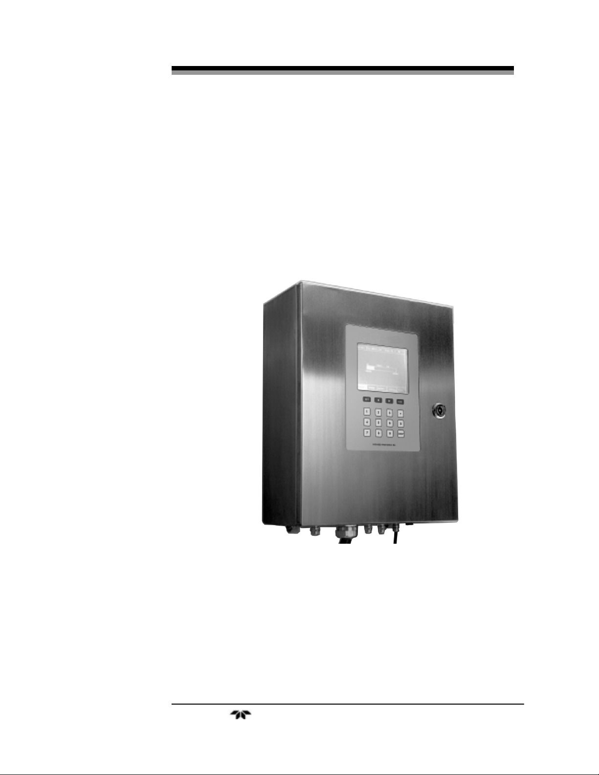
The central processing or control unit is a separate wall-mounted
enclosure located remotely from the process or point of analysis. It
houses the system electronics and includes the operator interface panel
on the front door. Figure 1 shows the Model 3500 control unit. A
separate enclosure is provided for the power supply
The operator interface consists of a panel of membrane switches for
controlling the operational mode of the instrument as well as entering
data. A large LCD display provides feedback to the user and indicates
the gas composition during analysis.
Figure 1-1 Control Section
The system is equipped with a separate power supply and output
control section which is also mounted remotely from the measurement
site. It houses power supplies and connectors for signal and relay output.
See Figure 1-2.
Teledyne Analytical Instruments 5
Page 20
Introduction Model 3500
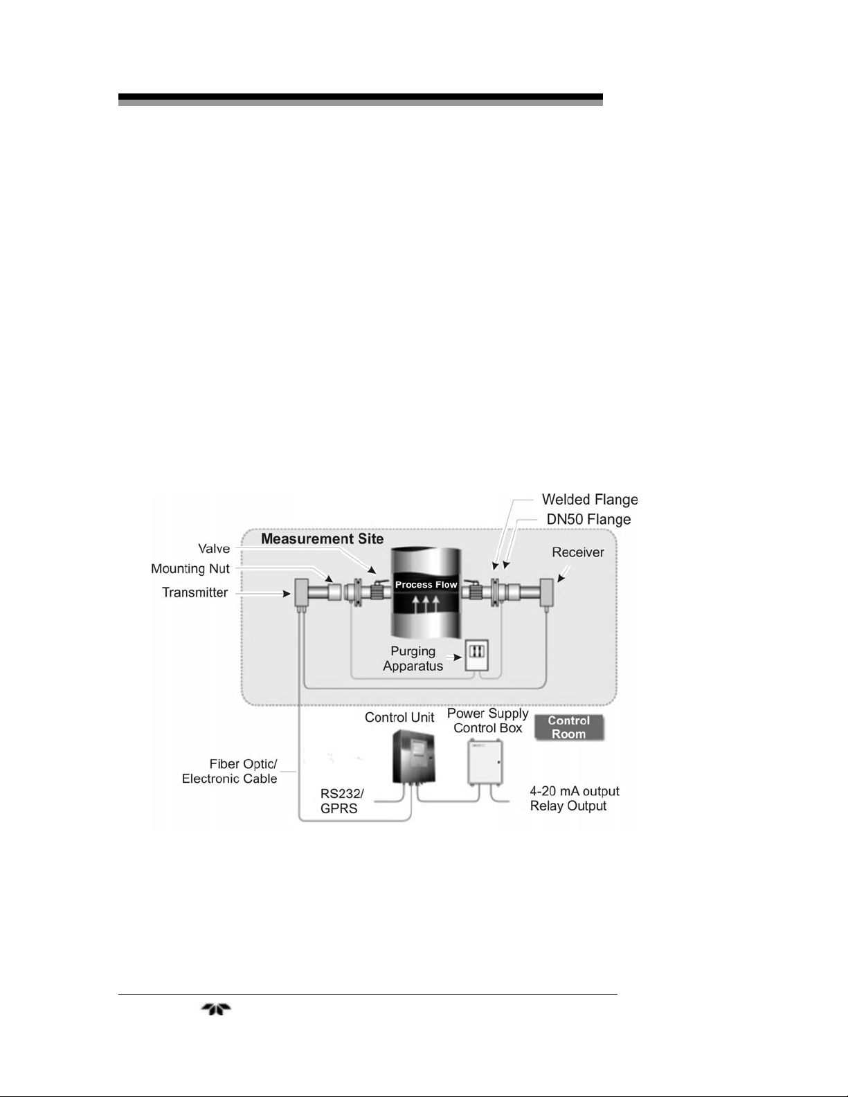
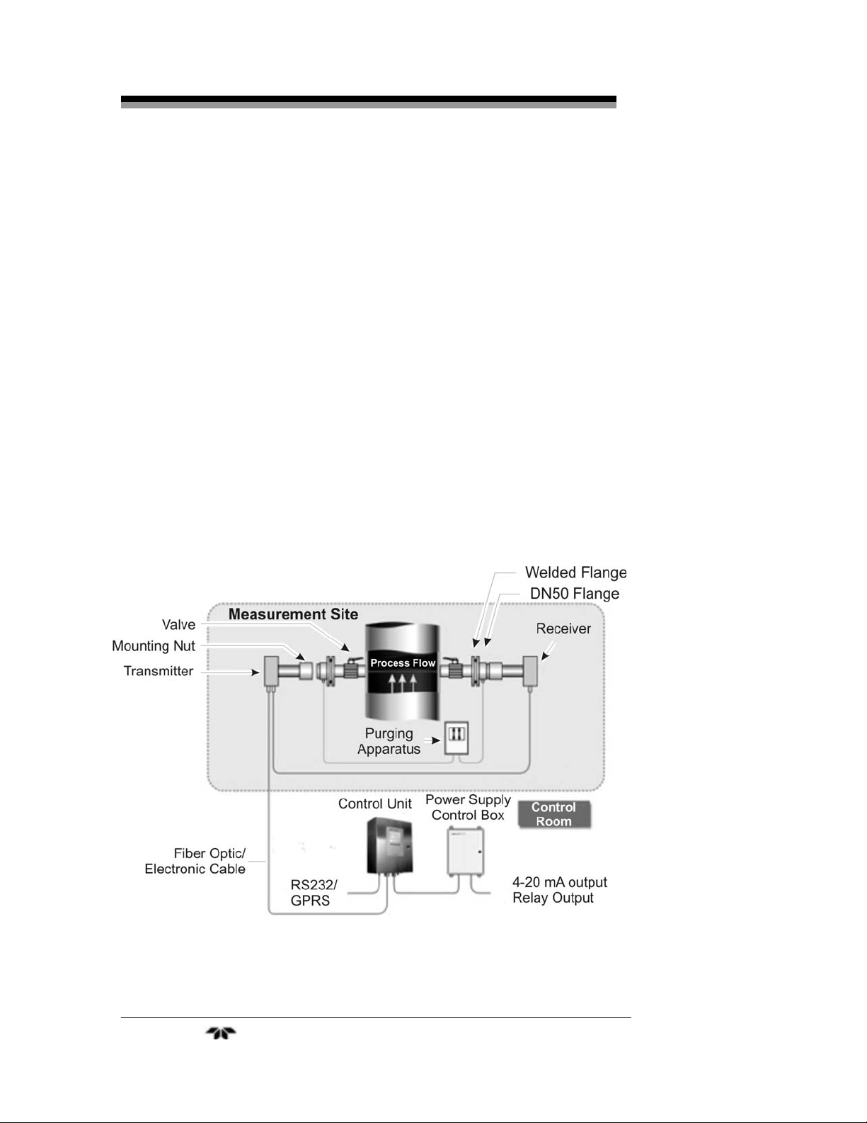
The analysis section is typically mounted at the point of
measurement and consists of the laser transmitter, receiver and flanges
for interfacing the unit with the process.
The transmitter unit and the receiver unit are mounted on flanges
which are welded onto the gas flow pipe. The transmitter is mounted
onto one flange with special adjustable fittings while the receiver is
mounted onto a similar flange diametrically opposed from the
transmitter. The transmitter unit launches a collimated laser beam into
the environment under test, and onto the sensor in the receiver unit. The
signal is sent to the central processing unit housed in the control unit.
An integral purging unit is incorporated to keep dust and gas
deposits from collecting on the analysis section windows thus
eliminating any interference or degradation of the laser induced signal.
Figure 1-2 shows a typical Model 3500 Laser Gas Analysis System
with the control section remotely located from the analysis portion.
Figure 1-2: Model 2500 Laser Gas Analysis System
Teledyne Analytical Instruments 6
Page 21
Laser Gas Analyzer Operational Theory
Operational Theory
2.1 Introduction
The Model 3500 Laser Gas Analysis System is a high precision gas
concentration measurement and monitoring system capable of on-thespot online operation. It is comprised of three subsystems:
1. Central Processing Unit (Control Unit)
2. Analysis Section
3. Purge System
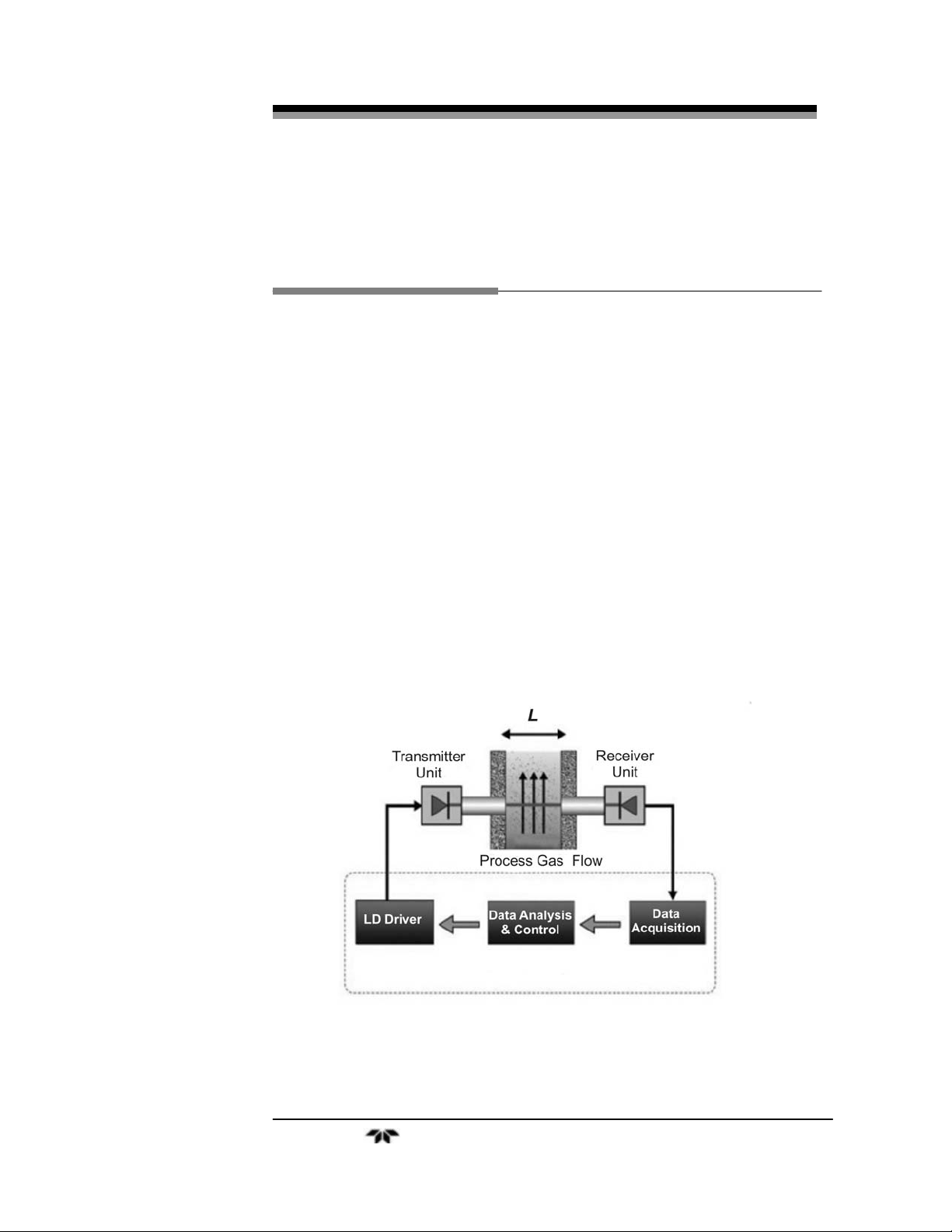
In the analysis section, the transmitter launches a laser beam across
the diameter of the industry pipe under test onto the receiver placed at
the other end. The resulting electrical signal is then sent to the central
processing unit and analyzed to yield the gas concentration and
displayed on the LCD screen. Signal and relay output is taken from the
power supply/control box. See Figure 2-1.
Figure 2-1: System Diagram for the Model 3500 Series Analyzers
Teledyne Analytical Instruments 7
Page 22

Operational Theory Model 3500
2.2 Principles of Operation
The Model 3500 Laser Gas Analysis System uses laser
spectroscopy to generate a signal based on the composition of a gas
mixture. While similar in nature to other photonic analyzers, the Model
3500 Laser Gas Analysis System offers many advantages over these
technologies.
Traditional online gas analyzers such as the Non-dispersive
Infrared (NDIR) Spectroscopy Online Gas Analyzer are subject to
interference from other constituents in the environment (including dust
and other gas species such as water vapor). This could be especially
severe when the measured gas is of low concentration. However, the
Model 3500 Laser Gas Analysis System series employ advanced Laser
Absorption Spectroscopy (DLAS) gas analysis and measurement
technology, i.e. “single-line” spectroscopic methods.
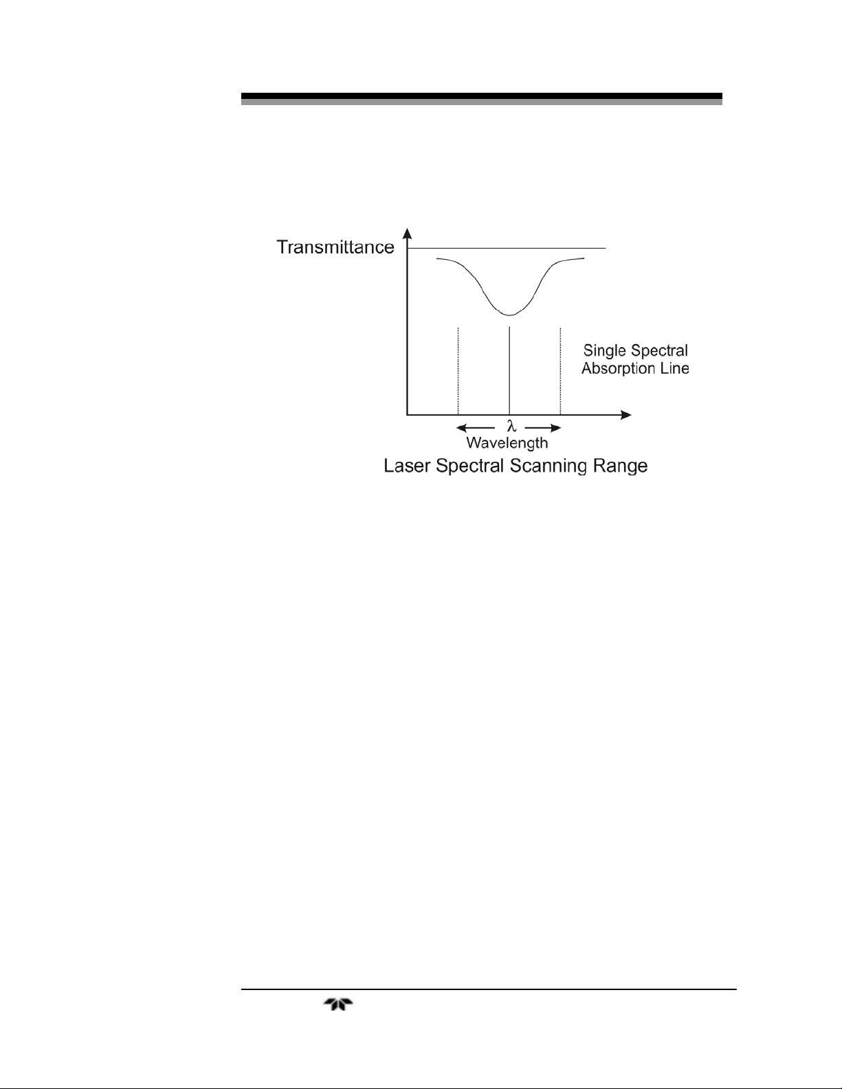
Conventional infrared spectroscopy uses light sources such as
lamps or LED’s that are normally non-laser and have very broad linewidths. The absorption spectrum obtained includes not only the spectral
lines from the gas under test, but also those from background gas species
which introduces cross interference. DLAS gas analyzers use diode
lasers that have line-widths of less than 0.0001nm, or only 1/106 of that
of the non-laser sources. By selecting a laser that will emit a specific
absorption line close to that of the gas under test and tuning its
wavelength through changing its temperature and driving current, an
absorption spectrum that only covers a single line of the gas under test
can be obtained and eliminates cross interference. See Figure 2-2.
The line-width of a diode laser is much narrower than that of the
gas molecule absorption spectrum. The Laser spectral line is depicted in
the figure as a light solid line.
The diode laser output from the transmitter goes through the
environment under test, gets absorbed by the target gas molecules, and
the resulted attenuated light is collected by the optical sensor in the
receiver unit. The attenuation is in proportion to the concentration of the
target gas. Varying the wavelength of the diode laser within the carefully
selected laser spectral scanning range (Figure 1.2), a gas absorption
spectral line without interference from the absorption spectra of
background dust and other gas species can be obtained for high
precision data analysis. This feature, no interference from background
dust and gases, enables the laser gas analysis systems to be applied on
the spot for online gas analysis. Conventional infrared spectroscopy, due
Teledyne Analytical Instruments 8
Page 23
Laser Gas Analyzer Operational Theory
to their vulnerability to interference from background gases and dust,
cannot or can hardly conduct on-the-spot measurement.
Figure 2.2 Schematic of “Single line” Spectroscopy.
The Model 3500 series of analyzers do not need complex gas
sampling and pretreatment. They have extremely quick response
because they skip the long gas sampling and transport process. As a
result, system maintenance is minimal since gas sampling and
pretreatment systems contribute to the majority of the maintenance
workload for conventional sampling gas analysis systems.
In conventional sampling gas analysis systems, it is the gas
concentration in the vicinity of the sampling tip that is sampled and
measured. Since gas concentration can have significant variance across
the section of gas flow pipe, inaccurate measurements result. No matter
how precise the subsequent data analysis is, the measurement results do
not accurately indicate the overall gas concentration in the gas flow pipe.
In contrast, the Model 3500 measures the average gas concentration
from the transmitter to the receiver. This represents the gas
concentration of the gas flow process much more accurately.
In addition, laser gas analysis systems have built-in temperature
and pressure auto-correction capability to enhance measurement
accuracy. These systems compensate for the temperature and pressure
Teledyne Analytical Instruments 9
Page 24

Operational Theory Model 3500
variance in the environment under test using a proprietary algorithm by
having input for temperature and pressure.
2.3 Software
An executable program is embedded program in the microprocessor
of the central process unit and is programmed to perform a multitude of
tasks including:
Signal processing
Data analysis
Managing system I/O including keyboard operations and display
Performs the system self-test
Calibration,
Alarm activation
In addition, the software establishes data communication with PC
through the RS232 serial communication port and GPRS modules. TAI
provides WINDOWS-based PC service program for all models in the
3500 series. Please refer to Appendix A for details.
Teledyne Analytical Instruments 10
Page 25

Laser Gas Analyzer Installation
Installation
Installation of the Model 3500 includes:
• Unpacking
• Mounting
• Flange connections
• Installing transmitter and receiver
• Electrical connections
• Optical transmission adjustments and fine tuning
3.1 Unpacking the Instrument
The unit is shipped with all the materials you need to install and
prepare the system for operation. Carefully unpack the analyzer and inspect
it for damage. Immediately report any damage to the shipping agent.
3.2 Installation Preparation
It is very important to prepare thoroughly before installing the
system. This includes having all the tools needed handy, choosing a
proper installation location, and correct welding of the flanges to the gas
flow pipe well. See section 3.3.1. Figure 3-1 shows the general layout of
the Model 3500 Laser Gas Analyzer.
3.2.1 Installation and Adjustment Tools
The following tools will be required for proper installation:
Wrenches M5 wrench—used to tighten the M5 bolts
connecting the instrument flange and
transmitter/receiver.
Two 12” adjustable wrenches—used to tighten
EMC and nut connector.
Teledyne Analytical Instruments 11
Page 26
Installation Model 3500
Two 8” adjustable wrenches—used to tighten
socket screws in purging system.
Socket screwdrivers M6 hexagonal socket screwdriver—used
to tighten M6 hexagonal socket bolt on the
receiver and transmitter box cover.
M5 hexagonal socket screwdriver—used to
tighten M5 hexagonal socket bolt on the receiver.
Screwdrivers 6mm slotted screwdriver—used to rotate the M8
fastening screws between the instrument and the
weld flanges, and the purging apparatus snap ring
screws.
3mm slotted screwdriver—used to connect
electric parts and components.
Digital multimeter.
Tubing cutter.
Tube bender for 6 and 12 mm tubing
Figure 3-1: General Layout of the Model 3500 Series Analyzer
Teledyne Analytical Instruments 12
Page 27

Laser Gas Analyzer Installation
3.2.2 Choosing Installation Spot
It is strongly recommended to install the system probes on a
straight section of the gas flow pipeline to ensure uniformity of the gas
flow. The length of straight pipe before the installation spot should be at
least twice (5 times, recommended) as much as the diameter of the pipe,
and half (twice, recommended) after the installation spot.
Note: The laser gas analysis system measures the average
concentration along the laser beam path (see Figure 1.2).
If there is no straight pipe section for mounting the flanges,
it may still be possible to get accurate measurements.
(Please contact our technical support center).
In addition, the installation spot should be chosen carefully
considering both safety and ergonomic factors. A platform should be
constructed when the chosen spot is not fully accommodating.
3.3 Analysis Section Installation
Installation of the analysis section involves:
• Welding flanges onto the process pipe
• Installing instrument flanges
• Checking the offset angle using the laser pen
• Adjusting the coaxial angle of the two instrument flanges,
• Installing the transmitter unit and the receiver unit.
3.3.1 Welding Flanges
The transmitter and receiver units of the analysis section are
mounted on DN50 flanges and mate to corresponding flanges which
must be welded onto the process pipe.
Note: The customer is responsible for correct welding of the
flanges onto the process pipe. The use of a competent
professional welder is required to ensure proper placement
of the flanges and provide a leak-free weldment.
The precision adjustment between the welding flange and the
instrument flange with the supplied O-ring can fine tune the optical
transmission to a limited extent. This allows for the two welding flanges
Teledyne Analytical Instruments 13
Page 28
Installation Model 3500
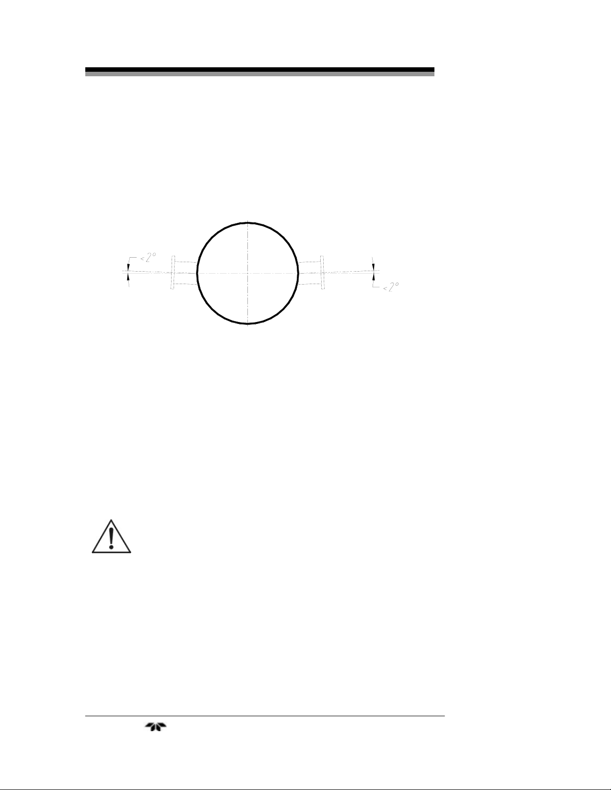
to have a limited coaxial offset between them. When welding the two
welding flanges the offset angle between their axes must be held to less
than 4°. Typically, the two welded flanges are positioned horizontally on
the gas flow pipe well across the pipe diameter As Shown in Figure 3-2.
Figure 3.2: Allowed offset for welded flanges
3.3.2 Installing Instrument Flanges
After welding the flanges, the Model 3500 probes can be installed.
Before installing, apply a lubricant to all the screw connections. To
make adjustments easier it is suggested that you use the adjusting aid
tools available from TAI (P/N XXXXX). These include a visible light
laser pen and a scaled target for alignment.
WARNING: POWER TO THE SYSTEM MUST BE OFF DURING
THE INSTALLATION OF THE TRANSMITTER AND
RECEIVER UNITS. DO NOT CONNECT OR SWITCH
ON THE POWER SUPPLY AT THIS STAGE. THE
LASER BEAM IS INVISIBLE AND CAN CAUSE EYE
DAMAGE.
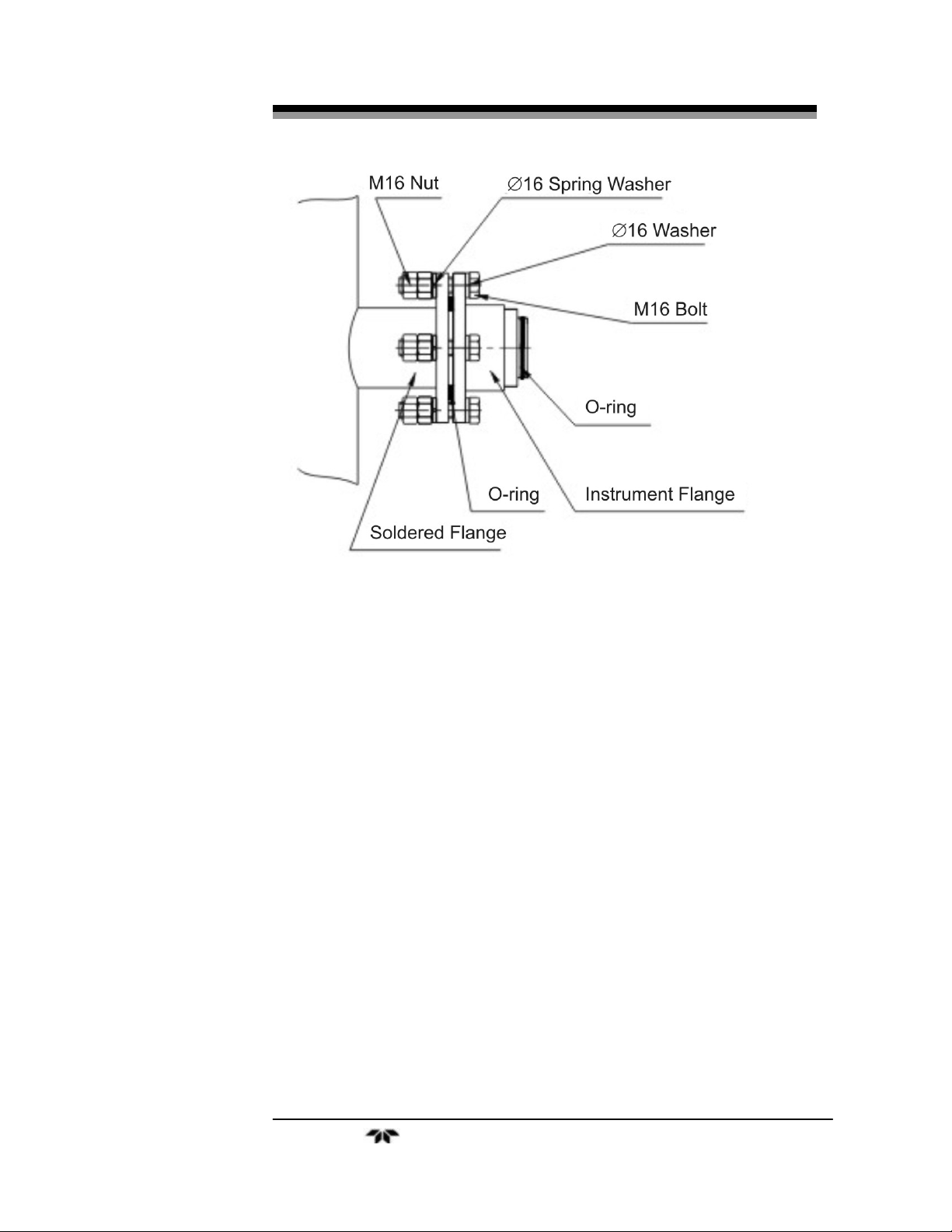
Mount the two instrument flanges onto the welded welding flanges
with 8 M16 bolts (with spring washer and plain washer) and 2 O-rings.
Raise the instrument flanges to the same height as the welded flanges,
then tighten the 8 M16 bolts to about half tight to make sure that the Orings are sealing. Typically the distance between the instrument flange
and the welding flange is around 3mm. See Figure 3.3.
Teledyne Analytical Instruments 14
Page 29
Laser Gas Analyzer Installation
Figure 3-3: Instrument Flange
3.3.3 Checking Offset Using the Laser Pen and Target
The laser pen is an optical transmission adjustment aid tool
available through TAI. The part number is listed in the Spare Parts List
in the Appendix. The laser pen emits visible red light beam and is used
to adjust the coaxial offset of the two instrument flanges. This assumes
that the welded flanges were installed correctly and held to within 4
degrees total offset with respect to each other.
Prior to adjusting the instrument flanges the laser pen must first be
checked for alignment.
3.3.3.1 CHECKING THE LASER PEN FOR ALIGNMENT
To see if the laser pen is suitable for your installation, apply the
following test:
1. Mount the laser pen on one instrument flange and the scaled
target onto the other instrument flange. Tighten with mounting
nuts.
2. Turn on the laser pen and observe the light spot on the target.
Teledyne Analytical Instruments 15
Page 30

Installation Model 3500
3. Loosen the mounting nut, rotate the laser pen around and tighten
the mounting nut again. Record the new light spot.
The trace of light spot on the target forms a circle. If the diameter
is less than 1/600 of the distance between the laser pen and the scaled
target, then the coaxial degree of the pen is adequate. Otherwise, please
contact our technical support center. See Figure 3.4.
3.3.3.2 ADJUSTING THE COAXIAL OFFSET OF THE INSTRUMENT FLANGES
To adjust the coaxial offset of the two installed instrument flanges
use the following procedure:
a. Tighten the laser pen on one of the instrument flanges with a
mounting nut. Install the scaled target on the other instrument
flange. Turn on the laser pen and check whether the light spot
is on the center of the scaled target. If not, adjust (tighten or
loosen) the 4 M16 bolts on the instrument flange where the
laser pen is mounted until the light spot is at the center of the
target. See Figure 3.4.
Figure 3.4 Adjusting the Instrument Flanges with Laser Pen and
Target.
4. Switch the laser pen with the scaled target, and redo step 1.
5. Redo step 2 repeatedly until the light spot is always at the center
of the scaled target without any adjustment.
6. Keep the laser pen on, tighten the 4 fastening screws on the
instrument flange where the laser pen is mounted, and keep an
eye on the light spot on the scaled target. If it moves, repeat steps
1, 2, and 3 until the light spot does not move.
Teledyne Analytical Instruments 16
Page 31

Laser Gas Analyzer Installation
7. Repeat step 4 to tighten 4 fastening screws on the other
instrument flange.
3.3.4 Installing the Transmitter Unit and the Receiver Unit
Mount the transmitter unit on one of the instrument flanges as
shown in Figure 3.1. Tighten it with the mounting nut, then tighten the
fastening screw. Mount the receiver unit the same way.
3.4 Central Processing Unit Installation
The central processing unit is a wall-mountable enclosure that is
hung on the wall of the instrument control center or in an analysis room
in the field. There are four pothooks on the housing for this purpose.
Secure the unit case to the wall using 4 M6 screws. Refer to Figure 3.5
for the case dimensions. The central processing unit should be hung at a
proper height for comfortable operation.
Figure 3.5 Dimension of the Central Processing Unit (in mm).
To avoid turning on the power supply inadvertently and possibly
causing harm to operators in the field, the central processing unit is
Teledyne Analytical Instruments 17
Page 32

Installation Model 3500
designed without a power switch. A separate wall mountable enclosure
is supplied for housing the power supply and switches.
CAUTION: DO NOT DISCONNECT THE CABLE BETWEEN THE
CENTRAL PROCESSING UNIT, THE TRANSMITTER
UNIT AND THE RECEIVER UNIT WHEN THE POWER
SUPPLY IS ON. THIS COULD CAUSE DAMAGE TO
THE LASER.
3.5 Purge System Installation
If dust or other pollutant concentration is relatively high in the
environment under test, a purging system must be installed to protect the
optical devices in the transmitter and receiver units.
In a typical purging system, the purge gas is directed through the
inside of the instrument flange, the welding flange or a special purging
pipe, and into the gas flow pipe. The purging gas forms an air wall to
protect the optical devices. The purge flow required depends on the
process environment. Usually, a purge gas flow rate in the range of 5-50
L/min×2 is required.
Compressed air or nitrogen is the most frequently used purging gas
sources. A filter should be installed to remove dust, water and oil
droplets larger than 1 micron in size before entering the system to
prevent the purge gas from contaminating the optical devices,. TAI
provides a range of purge systems for various applications and most are
equipped with appropriate filters. Please contact technical support if
your application requires a purge system.
A typical purge system is shown in Figure 3.6. This unit uses
compressed air (or nitrogen) as the purge gas and includes a 1 micron
filter. Two needle valves and flowmeters are installed to monitor and
control the purge rate to the transmitter and receiver. The housing is
equipped with a window for visual access while the housing door is
sealed.
To install the purge unit, connect each gas outlet of the purge
system to a purge inlet on the instrument flanges. Connect the inlet to a
suitable purge gas supply. A regulator should be used to control the
pressure to the purge system. The gas pressure depends on the particular
purge system installed and will be noted on the unit.
Teledyne Analytical Instruments 18
Page 33

Laser Gas Analyzer Installation
Open the gas supply and set the regulator to the proper pressure.
Turn the needle valve on the flow meter to the maximum, and then
adjust the needle valve adjacent to the flow meter to get the required
flow rate.
CAUTION: THE PURGE FLOW SHOULD REMAIN ON AFTER
THE POWER TO THE UNIT HAS BEEN TURNED OFF.
THIS PREVENTS DUST AND OTHER POLLUTANTS
IN THE ENVIRONMENT UNDER TEST FROM
CONTAMINATING THE OPTICAL DEVICES IN THE
TRANSMITTER AND RECEIVER UNITS.
Figure 3.6 Typical Purging System for the Model 3500
3.6 Electric Wiring and Connection
Depending on the instrument configuration, the Model 3500 Laser
Gas Analysis System can be categorized as Non-fiber optic and Fiber
optic. Non-fiber optic models (C option) use diode lasers without a fiber
pigtail. In these models, the laser diode is located in the transmitter unit.
The fiber optic models (F option) use a fiber pigtail to transmit the laser
Teledyne Analytical Instruments 19
Page 34

Installation Model 3500
radiation to the process. In these models, the laser diode is located in the
central processing unit, and the laser output beam is sent to the
transmitter unit through optical fiber. The electrical connections are
slightly different between the two models as shown in Figures 3.7 and
3.8. These figures show the connection ports on the central processing
unit for non fiber optic unit (Figure 3-7) and the fiber optic unit (Figure
3-8). Both instruments use 250V/2A fuses.
The Model 3500 provides input, output, and communication ports
on the bottom of the central processing unit enclosure. The following
input/output/communication signals are supported:
Output: 3-channel relay alarm output
1 4-20mA gas concentration output
Input: 2 4-20mA pressure and temperature input
Comm: 1 channel RS232/GPRS port for communications
with PC.
The input and output signal lines are connected to the motherboard
inside the central processing unit via a connection socket. Table 3.1
shows the specific electric connection for different input and output
signals. Customers may choose to connect these signal lines according
to their needs.
1. Grounding pole
2. RS232 connection port
3. Cable port between the
central processing unit and
the probe
4. 4-20mA connection port
5. Relay connection port
6. Fuse socket
7. Power supply port
Figure 3.7 Electric Connection Ports on the Central Processing
Unit for Non-fiber Optic Analysis Systems.
Teledyne Analytical Instruments 20
Page 35

Laser Gas Analyzer Installation
1. Grounding pole
2. RS232 connection port
3. Cable port between central
processing unit and the
probe
4. 4-20mA connection port
5. Relay connection port
6. Fuse socket
Figure 3.8: Electric Connection Ports on the Central Processing
Unit for Analysis Systems Using Fiber Optic Pigtail
Table 3.1 Electric connections & definitions of Input, Output Signals of
Central Processing Unit
Socket No. On
Motherboard
31 5V Power Supply
32 DGND Power Supply Ground
33 RS232-RXD
34 RS232-GND
35 RS232-TXD
36 4-20mA Concentration Output (-)
37 4-20mA Concentration Output (+)
38 4-20mA Pressure Input (-)
39 4-20mA Pressure Input (+)
40 4-20mA Pressure Input24V Power Supply
41 4-20mA Temperature Input (-)
Name
42 4-20mA Temperature Input (+)
43 4-20mA Temperature Input 24V Power Supply
44 Warning Alarm Relay 1
Teledyne Analytical Instruments 21
Page 36

Installation Model 3500
45 Warning Alarm Relay 2
46 Error Alarm Relay 1
47 Error Alarm Relay 2
48 Concentration Alarm Relay 1
49 Concentration Alarm Relay 2
WARNING: TURN OFF THE POWER BEFORE ELECTRIC WIRING.
OTHERWISE THE SYSTEM WOULD BE DAMAGED.
3.7 Optimize of the Optical Transmission Alignment
At this point, the installation and initial adjustment of all
components have been completed and the instrument can be powered
up.
Turn on the power supply. The LCD screen displays the startup,
initializing, and self test screens successively. Images of these screens
can be found in the next section as Figures 4.2, 4.3, and 4.4 respectively.
If the self test is successful, the LCD screen will then display
measurement and status information. Note the transmittance value on
the status bar. If this value is greater than 80%, then the installation and
adjustment step is successful and the system can be placed in service.
Otherwise, follow the steps below to fine tune and optimize the optical
transmission between the transmitter unit and the receiver unit.
a. Open the receiver unit box cover.
b. Use a voltage meter to measure the voltage between 3(+) and
4(-) of the wiring extremity. When the optical transmission is
optimized, the voltage is about 4.2V.
c. Loosen the 4 fastening screws on the instrument flange
where the transmitter unit is mounted (see Figure 3.3). Adjust
the flange by either tightening or loosening the 4 M16 bolts
until the measured voltage stabilizes to its maximum value.
Tighten the four fastening screws.
d. Replace the box cover.
Teledyne Analytical Instruments 22
Page 37

Laser Gas Analyzer Operation
Operation
The executable embedded program in the MCU of the central
process unit performs signal processing and data analysis, manages
system I/Os including keyboard operations and LCD, and runs system
self-test, calibration, and alarm. Furthermore, it establishes data
communication with PC through RS232 serial communication port and
GPRS modules. FPI provides WINDOWS-based PC service program for
all models of LGA-2000 analysis systems. Please refer to Appendix A
for details.
4.1 Front Panel
The Model 3500 front panel consists of a LCD screen and a 16 key
membrane keyboard. The LCD screen displays system information as
described in the following sections. The membrane keyboard is used to
carry out all user operations such as setting alarm parameters, setting
environment temperature and pressure, setting the optical path length,
doing system calibration, etc. The front panel is showed in Figure 4.1.
Figure 4-1: Model 3500 Series Front Panel
Teledyne Analytical Instruments 23
Page 38

Operation Model 3500
There are 16 available keys on the membrane keyboard. They
include 2 function keys (SET and ESC), 2 direction keys for navigation
(<,>), 0-9 digit keys plus a decimal point for input, and a backspace key
(BKSP). They function as follows:
• “SET” is a function keystroke. Press it to enter sub menu or
confirm data input.
• “<” And “>” are direction keystrokes. They are used to move the
cursor.
• “ESC” is a function keystroke. Press it to exit the sub menu and
go back up the menu, or to cancel the input data.
• “0-9” are digit keystrokes. They are for number input.
• “.” is the decimal point.
• “BKSP” is the backspace keystroke. It is used to delete the last
input digit.
4.2 System Mode
During operation the Model 3500 Laser Analysis System can be in
three different modes.
• Start-up Mode
• Normal Mode
• Error Mode
4.2.1 Start-up Mode
When the power is turned on, the system will automatically invoke
the start-up mode. In this mode, the system initializes and performs the
self-test routine.
The first menu on LCD screen is the start-up menu and shows the
company logo and name, instrument model and name. See Figure 4.2.
Teledyne Analytical Instruments 24
Page 39

Laser Gas Analyzer Operation
Figure 4.2 System Start-up Screen
After two seconds, the system enters the initialization stage. The
process lasts 5 seconds. Figure 4.3 shows the system init menu on LCD
screen displaying “ System initializing…” status.
Figure 4.3 System Init Screen
After initialization, the system starts the self test routine to examine
whether the system function modules are working properly. Normally,
the process takes about 6 minutes. Figure 4.4 is the system self test
screen showing “System Selftesting…” status. If everything is OK,
Teledyne Analytical Instruments 25
Page 40

Operation Model 3500
system the self test ends and the system automatically enters normal
mode. In the normal mode, the LCD displays system information.
Figure 4.4: Self Testing Screen
4.2.2 Normal Mode
In the normal mode, the system performs gas concentration
measurement and monitoring. There are two different working states
within the normal mode:
Normal working status: In this state, the system is measuring
normally. The LCD shows the measured gas concentration value and
other system information; “Normal” is shown on the status bar. The
analog output port (4-20mA) sends out the corresponding measured
value.
Warning working status: When the system finds that the system
external input parameters (mainly the pressure and temperature of the
gas under test) are abnormal or the optical transmittance is too low, it
automatically switches to warning working status. In this status, the
front panel of the LCD shows the corresponding warning signal (Alarm
code on the status bar, and warning symbol
in MainMenu in
graphics mode). The system computes the gas concentration value using
default values for input parameters and sends out 4-20mA output
CAUTION: SCREEN DISPLAY OF THE MEASURED
CONCENTRATION MAY BE HIGHLY INACCURATE IN
THIS MODE.
Teledyne Analytical Instruments 26
Page 41

Laser Gas Analyzer Operation
4.2.3 Error Mode
When the analysis system detects any fatal error that may damage
the system permanently (for instance, when the temperature in the
central processing unit is too high or the temperature of the laser device
is abnormal), the system automatically switches from start-up mode or
normal mode to error mode. In this mode, the system will stop gas
concentration measurement and most system operations, and enter
protection status. The front panel on LCD shows the corresponding error
information (Alarm code in the status bar, and error symbol in
MainMenu in graphics mode). The output ports (4-20mA and relay) still
send out alarm information.
4.3 System Menu
The Model 3500 operation interface employs a user-friendly menu
structure. There are six main menus:
• MainMenu
• Display
• System
• Cali.
• Com.
• Alarm
The entire menu has a simple and clear structure as shown in Figure
4.5 and is easy to operate.
Teledyne Analytical Instruments 27
Page 42

Operation Model 3500
Figure 4.5: System Menu Structure
4.3.1 MainMenu
MainMenu is the menu displayed after the system finishes start-up,
initializing and selftesting, and enters normal working status. The
MainMenu has two display modes—graphics, and numeric. The two
modes are switched through the Display menu. The graphics mode is
shown in Figure 4.6.
Teledyne Analytical Instruments 28
Page 43

Laser Gas Analyzer Operation
a
b
c
d
Figure 4-6: MainMenu—Graphic
The meaning of each location on the menu is described below:
e
f
g
h
a. Menu name (the same for all the other menus)
b. The name of the gas under test
c. Bar that shows measured gas concentration value
d. The button pointing to sub menus. When the cursor is on the
button, it is highlighted. Press SET to enter the submenus.
(Functions the same for all the other menus).
e. Status bar that shows the current measured gas concentration
value and the working status of the system (If everything is
OK, it displays Normal; Otherwise, it gives the Alarm Code).
(Functions the same for all the other menus).
f. Average gas concentration value
g. Units for gas concentration
h. Upper limit of gas concentration alarm range. The lower limit
is shown on the left side. These two values can be reset from
the Alarm menu.
The numerical value mode is shown in Figure 4.7.
Teledyne Analytical Instruments 29
Page 44

Operation Model 3500
Figure 4.7 Numerical Value Mode of the MainMenu
The meaning of each item on the menu is listed below:
• Current concentration: the gas concentration value just measured
• Average concentration: gas concentration value after digital
filtering. It can alleviate the influence caused by the uncertainty
of gas flow.
• Standard dev: standard deviation of the measured gas
concentration.
• Gas temperature: the temperature of the gas under test.
• Gas pressure: the pressure of the gas under test.
• Ave. times: Number of times used in digital filtering.
• Trans: Transmittance of laser beam in the environment under
test. If the optical windows in the transmitter and the receiver are
contaminated by dust in the environment under test, or if the
optical path between the transmitter and the receiver deviates
from the optimal position, the transmittance decreases.
• Con. output--4mA: gas concentration value corresponding to
4mA of the 4-20mA gas concentration output.
Teledyne Analytical Instruments 30
Page 45

Laser Gas Analyzer Operation
τ
τ
• Con. output--20mA: gas concentration value corresponding to
20mA of the 4-20mA gas concentration output.
• System time: the time of system clock.
• System date: the date of system clock.
Note: The Model 3500 outputs average gas concentration at the
4-20mA gas concentration output port.
The computation method for average concentration and standard
deviation is described below:
Average Concentration
1
g
new
N
g
cur
1
⎛
⎜
⎝
⎞
g
−+=
1
⎟
N
⎠
old
Where:
g ——Average concentration value
new
g ——Current concentration value
cur
g —— the average concentration value before adding the
old
latest measurement
g
stored in the system memory
cur
N ——Ave. times
The method is in equivalent to having the current concentration
value pass through a low-pass filter with a cut-off frequency at
1
f
=
2
N
τπ
, where
measurement. Typically, the Model 3500 series instruments have
is the time the system needs to finish one
set
at ∼1 second at the factory. However, it can also be set at any value in
the range of 0.1~1 second upon customer request to suit particular
applications that require faster response time. Contact technical support
for more information.
Normally, every time the system finishes one measurement cycle,
the LCD display and output at the 4-20mA output port refreshes.
Standard Deviation
Teledyne Analytical Instruments 31
Page 46

Operation Model 3500
+++
In a sequence of the last k current concentration values:
CCCC ,,,.......
. The average value of the sequence is:
nnnkn
121 −−+−
=
C
...
CCC
nnkn
−+− 11
.
k
The standard deviation of current gas concentration is given by:
2
=
e
n
1
1
−+−
1
−
k
22
)()(...)(
−+−++−
CCCCCC
nnkn
.
The Model 3500 sets k to 20 by default. For a strictly random
concentration sequence, statistically, different k produces the same
standard deviation.
Note: The 4-20mA output port on the Model 3500 outputs the
average gas concentration value computed with the above
method, the standard deviation at the port is therefore
about
N1
of the value displayed on the LCD, where, N
is the average times set by the user.
In the MainMenu, there are 5 submenus: Display, System, Cali.,
Com. and Alarm. In the MainMenu, the system only reacts to “SET”,
“<” and “>”. All the other keystrokes are disabled.
Press “SET”—the system enters the submenu selected by the
cursor.
Press “<”—the cursor moves one position left. If the cursor is
already on the leftmost button, the cursor moves to
the rightmost button.
Press “>”—the cursor moves one position right. If the cursor is
already on the rightmost button, the cursor moves to
the leftmost button.
By operating the above keystrokes, you can enter the submenu of
MainMenu:
the
• Display: Press “SET”—the system enters the Display menu.
• System: Press “SET”—the system asks for Sys Pwd. If the
password is correct, the system enters the
Teledyne Analytical Instruments 32
System menu.
Page 47

Laser Gas Analyzer Operation
• Cali.: Press “SET”—the system asks for Cali Pwd. If the
password is correct, the system enters the
• Com.: Press “SET”—the system enters the Com. menu.
• Alarm: Press “SET”—the system enters the Alarm menu.
4.3.2 Display
Cali. menu.
In Display menu, there are five submenus, Mode, Unit, Language,
TimeDate and Admin. See Figure 4-8. Pressing “<”,”>” and “SET”,
users can select display mode, unit of parameters, language
(English/Chinese), set system clock time and date, and change
passwords. Press “ESC”, the system goes back to the
MainMenu.
Figure 4.8 Display menu
• Mode: Press “SET”, a small window popes up, asking the user to
choose between Numerical Value Mode and Graphics Mode.
The difference between the two display modes is described in
Section 4.3.1
MainMenu.
Teledyne Analytical Instruments 33
Page 48

Operation Model 3500
Figure 4.9 Display Mode Options
• Unit: Choose unit for different parameters. Press “SET” to enter
Unit submenu.
Figure 4.10 Unit Menu
Teledyne Analytical Instruments 34
Page 49

Laser Gas Analyzer Operation
Users can set the unit for concentration, length, temperature and
pressure by pressing “SET” in different cursor locations. For example,
press “SET” when the cursor is on
Con. Unit, the system enters the
following menu:
Figure 4.11 Set Con. Unit menu
The following units for concentration, length, temperature and
pressure are available:
• Con. Unit: ppm, %, g/m
3
, g/Nm3, mg/m3, mg/Nm3
• Len. Unit: m, cm, ft, inch
• Temp. Unit: °F, K, °C
• Pres. Unit: bar, Pa, mbar, psi, Mpa
Six units are provided in the
%, g/m
3
, g/Nm3, mg/m3, and mg/Nm3. Units in ppm and % are
commonly used for volume percentage concentration while g/m
3
mg/m
are mass volume ratio concentration units related to volume
percentage concentration through the ideal gas equation
Con. Unit menu to choose from: ppm,
3
and
. The units
g/Nm3 and mg/Nm3 are mass volume ratio concentration units (standard
state , pressure: 1.01325Bar, temperature: 273.1K).
Teledyne Analytical Instruments 35
Page 50

Operation Model 3500
• Language: Press “SET” to select between Chinese and English.
Figure 4.12 Pop-up Window for Language Selection
After the selection, all menus are in the language selected.
• TimeDate: Press “SET” to set system clock time and date.
Figure 4.13 TimeDate Menu
Teledyne Analytical Instruments 36
Page 51

Laser Gas Analyzer Operation
• Admin.: Press “SET”, the system asks for Pwd. If the Pwd is
entered correctly, the system enters the
Admin. menu. (Figure
4.14).
Figure 4.14 Admin. Menu
From the Admin screen you can change passwords and update the
system software. The selectable items are:
• Change Admin. Pwd: change the password to Admin. menu.
(Figure 4.14).
• Change Sys. Pwd: change the password to System menu (Figure
4.15).
• Change Cali. Pwd: change the password to Cali. menu (Figure
4.23).
• Update instrument software: press to enter software update
interface to upgrade system software.
To change the passwords of
System and Cali., you must enter the
Admin. Menu. The user who has the Admin. password has the highest
authority. With this privilege you can reset
System pwd and Cali. pwd
to ensure authorized system management.
Teledyne Analytical Instruments 37
Page 52

Operation Model 3500
The default Admin. Pwd is 2222. The default System. Pwd is
1111. The default
Cali. Pwd is 3333.
Additional information about software updates is available through
the technical support center.
4.3.3 System
System menu includes System main menu and System sub menu.
In the
MainMenu, move the cursor to System and press “SET”, the
system asks for password, if the password keyed in by the operator is
correct, the system enters the System main menu.
Note: In error mode, the system is in Error Protection Menu (see
Figure 4.39), and the System main menu is not accessible.
a
b
c
Figure 4.15 System main menu
The system main menu is shown in Figure 4.15. The data fields for
this menu are as follows:
d
• Path length: optical path length of the gas under test.
• Gas temperature: temperature of the gas under test.
• Gas pressure: pressure of the gas under test.
Teledyne Analytical Instruments 38
Page 53

Laser Gas Analyzer Operation
• Average times: number of times used to calculate average
concentration.
• Con. output--4mA: gas concentration value corresponding to
4mA of the 4-20mA gas concentration output.
• Con. output--20mA: gas concentration value corresponding to
20mA of the 4-20mA gas concentration output.
• Purge parameter: purging system parameters including the
length, temperature and density of the purging gas. Interaction
with the purge system is done through this menu.
• Transmission: Transmittance of laser beam in the environment
under test.
On this menu, the operator can move the cursor to a parameter
button, press “SET”, and a pop-up window occurs for the operator to
reset it (Figure 4.15). The items in the column refer to:
Item name
a.
Value
b.
Unit
c.
Way to set the item (key in manually or from a measurement).
d.
None will be shown here if it can only be keyed in.
4.3.3.1 SYSTEM PARAMETER INPUT METHOD
As an example, the following demonstrates the way to reset optical
path length.
Move the cursor to “Length” button and press “SET”. The Path
1.
length input window pops up.
Teledyne Analytical Instruments 39
Page 54

Operation Model 3500
Figure 4.16 Set Optical Path Length
2.
Key in the new optical path length value (Figure 4.17).
a
Figure 4.17 Input the New Optical Path Length Value
3.
Press “SET” to accept the new setting.
b
c
d
The call-outs on Figure 4.17 refer to:
Teledyne Analytical Instruments 40
Page 55

Laser Gas Analyzer Operation
a. Item name
b.
Unit of the item
Current value
c.
New data input. The underscore after the number shows where
d.
the next digit goes.
Note: After the system parameter input window pops up,
keystrokes “<” and “>” are disabled.
The “SET” key is used to accept the new setting and close the input
window. If no data is keyed in, and “SET” is pressed, the system
defaults to 0. If the data keyed in is out of range, an error alert is issued.
Use the “ESC” key to reject the new setting and close the input
window. The “ESC” key is used when you have input wrong data and do
not want the system to accept it.
The numerical keys “0-9” are used to enter data digits. The
underscore moves a position to the right with each input. Similarly, the
decimal point key “.” Is used to input the decimal point.
The Backspace key, “BKSP”, is used to delete the last data digit,
The underscore moves a position to the left with each deletion.
4.3.3.2 SYSTEM SUB MENUS
The sub menus of the System menu are:
• Path: —set optical path length value (0-12m), manual.
• Temp: — set temperature of the gas under test (200-3000) K,
manual or from a measurement. When choose Measure, the
system enters Measured Temperature Set menu.
• Pressure: —set pressure of the gas under test (0-20) bar, manual
or from a measurement. When choose Measure, the system
enters Measured Pressure Set menu.
• Av Times: —set number of times used to calculate average
concentration (0-90), manual.
• Out Set: —set the range of 4-20mA concentration output.
• Purge: —set parameters of the purging gas including purging gas
concentration, purging path and purging gas temperature.
Teledyne Analytical Instruments 41
Page 56

Operation Model 3500
• Apply: —after entering all the data, press this button to finish the
process.
Additional sub menus are located on the next screen. Move the
highlighted button to the ---- > symbol and press “Set”.
The additional system sub menus areas follows:
1. Measured Temperature Menu
Figure 4.18 Measured Temperature Menu
Items displayed on the Measured Temperature screen (Figure 4.18) are:
• Temp.input--4mA: The gas temperature input is taken from a
measurement. It is input to correspond with a 4-20mA output
signal. Temp.input--4mA is the gas temperature corresponding to
4mA.
• Temp.input--20mA: This is also taken from a measurement. It is
the gas temperature corresponding to 20mA.
The buttons on this menu refer to:
4mA: Set the corresponding gas temperature when the
temperature input signal is 4mA.
20mA: Set the corresponding gas temperature when the
temperature input signal is 20mA.
2. Measured Pressure Menu
Teledyne Analytical Instruments 42
Page 57

Laser Gas Analyzer Operation
Figure 4.19: Measured Pressure Menu
Items displayed on the Measured Pressure screen (Figure 4.19) are:
• Pres. input--4mA: The gas pressure input is taken from a
pressure measurement. It is input to correspond with a 4-20mA
output signal. Pres. input--4mA is the gas pressure corresponding
to 4mA.
• Pres. input--20mA: This is also taken from a measurement. It is
the gas pressure corresponding to 20mA.
The buttons on this menu refer to:
4mA: Set the corresponding gas pressure when the pressure
input signal is 4mA.
20mA: Set the corresponding gas pressure when the pressure
input signal is 20mA.
3. Concentration Output Menu
Items displayed on the Concentration Output screen (Figure 4.20)
are:
• Con. output--4mA: The measured gas concentration output is in
the form of 4-20mA. Con. output--4mA is the gas concentration
value corresponding to 4mA.
Teledyne Analytical Instruments 43
Page 58

Operation Model 3500
• Con. output--20mA: The measured gas concentration output is in
the form of 4-20mA. Con. output--20mA is the gas concentration
value corresponding to 20mA.
Figure 4.20 Concentration Output Menu
The buttons on this menu refer to:
4mA: Set the corresponding gas concentration (0-
99.9999)% when the gas concentration output signal
is 4mA.
20mA: Set he corresponding gas concentration (0-99.9999)%
when the gas concentration output signal is 20mA.
4. Purge Parameter Menu
On the Purge Parameter Menu (Figure 4.21), the selections are:
• Pur Len: Set the purging path length (Lf2+Lf1+Lb1+Lb2, Figure
4.22).
• Pur. Temp: Set the purging gas temperature.
• Pur. Con.: Set the concentration of gas under test in the purging
gas.
Teledyne Analytical Instruments 44
Page 59

Laser Gas Analyzer Operation
Figure 4.21 Purge Parameter Menu
Figure 4.22 Schematic showing purging gas channel
Note: The residual gas in LF3 and LB3 has been interpreted
during zeroing, and thus has no influence on the
Teledyne Analytical Instruments 45
Page 60

Operation Model 3500
measurement result.
4.3.4 Cali.
Cali. main menu is third from left on MainMenu. Pressing “SET”,
the system prompts for the password, if the password is entered
correctly, the system enters
Cali. main menu. (Figure 4.23)
Note: In error mode, the system is in Error Protection Menu (see
Figure 4.39), and the Cali. menu is not accessible.
Figure 4.23 Cali. Main Menu
From this menu, the operator can perform the following operations:
• Adjust zero point: Fill the calibration tube with standard gas
(such as high purity nitrogen) with 0% of the gas under test, and
zero calibrate.
• Calibrate coefficient: Fill the calibration tube with standard gas
(such as high purity Nitrogen) with known concentration of the
gas under test, and perform a span calibration operation.
Note: Perform the zero calibration before doing the span
calibration.
Teledyne Analytical Instruments 46
Page 61

Laser Gas Analyzer Operation
• Backup coefficient: Save current calibration coefficients as
backup. The operator can choose to backup any set of calibration
coefficients they are satisfied with. The Model 3500 has
calibration coefficients backed up before shipping.
• Restore coefficient: When the users are not happy with the
current calibration result, and are unable to get good calibration
results, they can restore the old more satisfying backup
calibration coefficients.
4.3.4.1 ADJUST ZERO:
Zero: Press “SET” when the cursor is on “Zero” button, the system
enters the Pre zeroing menu (Figure 4.24).
Figure 4.24 Pre zeroing sub menu
Choose “Accept” to accept the parameters, and the system starts
zeroing (Figure 4.25). The zeroing gauge bar shows the progress of the
process.
Teledyne Analytical Instruments 47
Page 62

Operation Model 3500
Figure 4.25 Zeroing menu
4.3.4.2 CALI. CO:
Figure 4.26 is the Cali.Co sub menu. On this menu, operators can
set calibration optical path length, temperature, pressure, concentration
parameters needed by the calibration system.
Figure 4.26 Calibration coefficient sub menu
Teledyne Analytical Instruments 48
Page 63

Laser Gas Analyzer Operation
The functions of the buttons on Cali.Co sub menu are:
• Cali.Len: Sets the optical path length of the calibration tube,
manual.
• Cali.Temp: Sets the temperature of the standard gas used for
calibration, manual or from a measurement. When “Measure” is
chosen, the system enters Measured Temperature Set menu.
• Cali.Pres: Sets the pressure of the standard gas used for
calibration, manual or from a measurement. When “Measure” is
chosen, the system enters Measured Pressure Set menu.
• Cali.Con: Enters the concentration value of the standard gas used
for calibration. This value is used to calculate calibration
coefficients.
• Pre.Cali: After inputting all the parameters above, press Pre.Cali
button to accept them, and the system enters the Calibration
Confirmation menu (Figure 4.27).
Note: The system accepts the above input parameters only after
Pre.Cali is pressed.
Figure 4.27 Calibration confirmation menu
Teledyne Analytical Instruments 49
Page 64

Operation Model 3500
The Calibration Confirmation menu (Figure 4.27) displays the
measured average gas concentration, standard deviation and the
concentration value of the standard gas (Calib. Concentration) which
were entered in the
Cali.Co sub menu (Figure 4.26).
Drift within a calibration interval is typically small in the Model
3500 series. If the measured average gas concentration differs
significantly from the entered Calib. Concentration, it is recommended
to choose “Cancel” to reject the calibration and check whether all
parameters on
Cali.Co sub menu (Figure 4.26) are correctly set. Check
also for leaks in the calibration system and whether the standard gas has
been in storage for too long a time..
Note also the standard deviation of the measured gas concentration.
If it is too large with respect to the measured gas concentration, i.e.
greater than 1%, the calibration inaccuracy would be high. Again, it is
recommended to choose “Cancel” to reject the calibration, and check
whether the gas concentration of the standard gas is too low. Make sure
you are using a standard with the recommended concentration value as
listed in the calibration parameter table that comes with the system.
If everything is OK, choose “Accept” to accept the calibration. The
system starts the calibration process and automatically displays the
calibration progression menu (Figure 4.28).
Figure 4.28 Calibration Progression
Teledyne Analytical Instruments 50
Page 65

Laser Gas Analyzer Operation
Note: The accuracy of the system depends on calibration. It is of
the utmost importance to perform a good, accurate
calibration. DO NOT accept any calibration that shows
abnormal behavior.
4.3.4.3 BACKUP
Backup saves the current calibration coefficients to memory. The
operator can choose to backup any set of calibration coefficients they are
satisfied with. The Model 3500 has calibration coefficients backed up
before shipping.
To backup the calibration parameters, move the cursor to the
“Backup” position and press “SET”.
4.3.4.4 RESTORE
If the current calibration parameters are found to be unsatisfactory,
you can restore previously stored backup calibration coefficients.
To restore the last saved parameters, move the cursor to the
“Restore” position and press “SET”. This loads in the last save
calibration parameters from memory replacing the currently displayed
values.
4.3.5 Com
On this menu, users can query the communication status of RS232.
Move the cursor to “Com.” on the Main Menu, and press “SET” to
enter the Com. Menu (Figure 4.29).
Teledyne Analytical Instruments 51
Page 66

Operation Model 3500
Figure 4.29 Com. Main menu
4.3.6 Alarm
Alarm is the fifth button from left on the Main Menu. Here the
operator can read system alarm information, modify alarm settings and
read previous alarm records.
Figure 4.30 Alarm main menu
Teledyne Analytical Instruments 52
Page 67

Laser Gas Analyzer Operation
Items displayed on the Alarms screen (Figure 4.30) are:
• System error: The latest system error
• System warning: The latest system warning
• Con. alarm: The latest concentration alarm
• Relay1: The status of warning alarm relay
• Relay2: The status of error alarm relay
• Relay3: The status of concentration alarm relay
• Alarm lower limit: The lower limit of the concentration alarm
range
• Alarm upper limit: The upper limit of the concentration alarm
range
The functions of the buttons on the AlarmSet screen are:
History: The last 20 alarm records after entering this sub menu
can be examined (Figure 31).
Figure 4.31 Alarm History Menu
Teledyne Analytical Instruments 53
Page 68

Operation Model 3500
AlarmSet: The users can set the range of concentration alarm,
enable the automatic recovery function of the alarm
relays and set their recovery time. (Figure 4.32)
Figure 4.32 AlarmSet menu
There are two buttons on AlarmSet menu: alarm concentration and
automatic recovery.
• Alarm concentration: Here you can set the concentration
for triggering a low and high alarm. (Figure 4.33)
• Automatic restoration: Here you can set whether the
alarm relay restores automatically after the alarm is
cleared as well as the corresponding restoration time. The
alarm relay restoration time is the time it takes for the
alarm relay to return to the non-alarm or closed state.
(Figure 4.34 and Figure 4.35)
Teledyne Analytical Instruments 54
Page 69

Laser Gas Analyzer Operation
Figure 4.33 Alarm concentration range menu
Figure 4.34 Menu to set automatic restoration
Teledyne Analytical Instruments 55
Page 70

Operation Model 3500
Figure 4.35 Time sequence of the alarm relay automatic
restoration
Relay: Here you can query and set the relay status after
entering relay menu. (Figure 4-36).
Figure 4.36 Relay Menu
Teledyne Analytical Instruments 56
Page 71

Laser Gas Analyzer Operation
4.3.7 Additional Menus
Three additional screens exist which are automatically invoked
depending on the status of the instrument. These are: Message Code,
Password Input, and Protection Mode Menu.
4.3.7.1 MESSAGE CODE:
Whenever there is an error, warning, or alarm, the system
automatically switches to MainMenu in graphics mode, and the
corresponding alarm icon and alarm code appear on the menu See
Figure 4.37. The specific message codes are listed in section 5.3.
The
icon is displayed when a warning or concentration alarm.
Is triggered
The
For alarms represented by
icon is used for an error.
(warning or concentration alarm),
the symbol disappears automatically when the alarm is cleared, and the
alarm code changes to “Normal”. The alarm relay, however, does not go
back to the “Close” state right away (see Automatic Restoration, Clear
Alarm Button).
Figure 4.37 Message code interface
Teledyne Analytical Instruments 57
Page 72

Operation Model 3500
The call outs on Figure 4-37 refer to:
a.
Message Code
Alarm Icon
b.
4.3.7.2 PASSWORD INPUT:
A password is required to enter system menu, cali. menu or admin.
menu. This is incorporated to protect the system from being modified by
unauthorized personnel.
Figure 4.38 Password input interface
4.3.7.3 ERROR PROTECTION MENU:
When the system is in error mode it is not possible enter the system
or calib. menu. Pressing “SET” when the cursor is on System or Calib.
brings up a special screen indicating that the system is protected. (Figure
4.39).
Teledyne Analytical Instruments 58
Page 73

Laser Gas Analyzer Operation
Figure 4.39 Error Protection Menu
Teledyne Analytical Instruments 59
Page 74

Operation Model 3500
Teledyne Analytical Instruments 60
Page 75

Laser Gas Analyzer Alarm Messages
Alarm Messages
Alarms installed in the Model 3500 include a 3-Channel Relay
Alarm, a 4-20mA output alarm, and LCD display of alarm information.
5.1 Relay Alarm
The 3-Channel Relay in the Model 3500 is set up as follows:
Relay 1—warning alarm relay
Relay 2—error alarm relay
Relay 3—concentration alarm relay
The concentration alarm relay is triggered when the measured gas
concentration has exceeded the high or low limits set by the user. When
this occurs, the relay opens indicating that the current concentration is
out of the set range.
The warning alarm and error alarm when triggered indicate that the
system working status is abnormal (warning status in normal mode and
system error).
Table 5.1 shows the relay and output state for various operational
modes of the model 3500.
5.2 4-20mA Analog Output
When the system status is normal, the 4-20mA analog output
represents the measured gas concentration. In general, 4-20mA
corresponds to the user-defined measurement range. 4mA corresponds
to the minimum value of the user-defined measurement range and 20mA
corresponds to the maximum. When the system encounters an error and
enters error mode, the output of the 4-20mA port is 2mA.
CAUTION: 2MA DOES NOT REPRESENT MEASURED GAS
CONCENTRATION. IT ONLY SHOWS THAT THE
ANALYZER HAS ISSUED AN ERROR ALARM.
Teledyne Analytical Instruments 61
Page 76

Alarm Messages Model 3500
Table 5.1 Relays and output status for Various Operation Modes
System Working
Status
Power-off
Start-up Mode
Normal
Normal
Mode
Error Mode
Status
Warning
Status
LCD
Status
Bar
No No Open = Alarm Open = Alarm Open (Alarm) 0mA
No No
Normal No
Alarm
Message
Code
Alarm
Message
Code
(Graphics
LCD
Alarm
Icon
Mode)
Warning
Alarm
(Relay_1)
Closed = No
Alarm
Closed = No
Alarm
Open = Alarm
Open = Alarm Open = Alarm
Relay
Error Alarm
(Relay_2)
Closed = No
Alarm
Closed = No
Alarm
Closed = No
Alarm
Concentration
Alarm
(Relay_3)
Closed = No
Alarm
Depending on
gas
concentration
Depending on
gas
concentration
Closed = No
Alarm
4-
20mA
Output
0mA
4-
20mA
4-
20mA
2mA
5.3 LCD Alarm Message Display
When the Model 3500 enters an alarm condition an alarm message
is displayed on the LCD screen. Detailed descriptions and solutions of
these messages are listed in Table5.2.
.
Teledyne Analytical Instruments 62
Page 77

Laser Gas Analyzer Alarm Messages
Table 5.2: LCD Display Alarm Messages
Relay Status
a. Warning Alarm
Alarm
Code on
LCD
02
03
11
13
15
17
18
57
58
05/06
Possible
Cause of the
alarm
Model 3500S
has internal
system error
The temperature
inside the Model
3500S central
processing unit
is too high/low.
b. Error Alarm
c. Conc. Alarm
(O=Open
C=Closed)
a=O b=O c=C 2mA
a=O b=O c=C 2mA
4-20mA
Output
Trouble shooting
Write down the alarm code;
power off the system; reboot
the system in an hour; If the
same alarm persists, contact
technical support center.
Power off the system; check
whether the environment
temperature inside/outside of
the central processing unit is
abnormal; reboot the system
after making sure that the
temperature is normal. If the
same alarm persists, contact
the technical support center.
Power off the system; reboot
the system in an hour; If the
same alarm persists, contact
the technical support center.
Power off the system; reboot
the system in an hour; If the
same alarm persists, contact
the technical support center.
08/09
20
The laser
temperature is
too high/low.
Background
radiation is too
strong during
system self test.
a=O b=O c=C 2mA
a=O b=O c=C 2mA
Teledyne Analytical Instruments 63
Page 78

Alarm Messages Model 3500
31/32
33
35/36
37
The pressure of
the gas
environment
under test
exceeds the
Model 3500S
application limit.
The sensor used
to measure gas
pressure is not
wired correctly.
The temperature
of the gas
environment
under test
exceeds the
Model 3500S
application limit.
The sensor used
to measure gas
temperature is
not wired
correctly
A=O b=C c=X
X means that it
depends on the gas
concentration value.
a=O b=C c=X
a=O b=C c=X
a=O b=C c=X
4-20mA,
the exact
number is
from
calculation.
4-20mA,
the exact
number is
from
calculation.
4-20mA,
the exact
number is
from
calculation.
4-20mA,
the exact
number is
from
calculation.
The gas concentration is
calculated with the pressure
limit; check the gas pressure in
the environment under test.
Note: In this situation, the
calculated concentration may
be inaccurate.
The gas concentration is
calculated with the default
pressure value; check the
wiring and working condition
of the pressure sensor.
Note: In this situation, the
calculated concentration may
be inaccurate.
The gas concentration is
calculated with the
temperature limit; check the
gas temperature in the
environment under test.
Note: In this situation, the
calculated concentration may
be inaccurate.
The gas concentration is
calculated with the default
temperature value; check the
wiring and working condition
of the temperature sensor.
Note: In this situation, the
calculated concentration may
be inaccurate.
Current
measured gas
41/42
43
Teledyne Analytical Instruments 64
concentration
exceeds the userdefined range
Model 3500S
EEPROM fault
a=C b=C c=O
a=O b=O c=C 2mA
4-20mA,
the exact
number is
from
calculation.
Power off the system; contact
the technical support center.
Page 79

Laser Gas Analyzer Alarm Messages
45
48
59
99
During the
measurement
process, the laser
power is too high
or the
background light
is too strong
The measured
gas
concentration
exceeds Model
3500S upper
limit for 1
minute.
Low
transmittance
due to
contamination to
the optical
window or the
dust density in
the environment
under test
exceeds normal
range.
Model 3500
internal
communication
error alarm (the
status shown on
LCD may not
reflect the actual
system working
status).
a=O b=C c=X
a=O b=C c=X
a=O b=C c=X
a=C b=C c=C
4-20mA,
the exact
number is
from
calculation.
4-20mA,
keep the
last
measured
value
4-20mA
4-20mA,
the exact
number is
from
calculation.
Reboot the system; If the same
alarm persists, and there is no
strong background light in the
gas flow pipe under test,
contact the technical support
center.
the same alarm persists, and
he gas flow is not abnormal,
ontact the technical support
enter.
Power off the system; clean
the optical windows (follow
the instructions in Users’
Manual); If the same alarm
still persists, contact the
technical support center.
Power off the system; reboot
the system in an hour; If the
same alarm persists, contact
the technical support center.
Teledyne Analytical Instruments 65
Page 80

Alarm Messages Model 3500
Teledyne Analytical Instruments 66
Page 81

Laser Gas Analyzer Maintenance and Calibration
Maintenance and Calibration
The Model 3500 Laser Gas Analysis System needs to be
maintained and calibrated periodically to ensure it is working properly.
6.1 Maintenance
There are no user serviceable parts within the Model 3500. Daily
preventive maintenance is limited to:
• Checking and adjusting the purge gas flow
• Visually inspecting and cleaning the optical devices
• Optimizing the optical transmission.
The Model 3500 Laser Gas Analysis System incorporates a purging
system to protect the optical parts in the transmitter unit and the receiver
unit from contamination by dust, water vapor, and process gas
deposition. Maintaining an appropriate purge gas flow rate is a key
factor in its ability to keep the components functioning. However, dust
and other pollutants in the environment still could contaminate the
optical parts during extended operation of the system which would result
in lower the transmittance between the transmitter and receiver as well
as influence the overall performance of the system. For this reason it is
important to clean the optical parts periodically. Drift in the optical
transmission alignment may also occur after a period of time, and needs
to be re-adjusted and optimized periodically.
The Model 3500 uses specially designed signal processing circuits.
As long as signal voltage from the sensor is no less than 30% of its
normal value, the system measurement and analysis performance is not
affected. It greatly reduces the demand of cleaning the optical parts and
re-adjusting the optical transmission alignment.
6.1.1 Adjusting the Purge Gas Flow
The purge system is equipped with a gas regulator which provides
steady purge gas flow even when the gas source pressure fluctuates over
a large range. However, if excessive dust or other particles are present in
Teledyne Analytical Instruments 67
Page 82

Maintenance and Calibration Model 3500
the purge gas source, the filter may clog after a period of time. This will
result in a fluctuation flow rate.
When a drop in the flow meter reading occurs, adjust the needle
valve (Figure 3.6) on the apparatus to increase the flow rate. If the
required flow rate cannot be achieved by opening the needle valve, the
filter is probably clogged and needs to be replaced.
To replace the filter cartridge:
Turn off the purge gas source.
1.
Remove the screw on the side of the purge housing and remove
2.
the filter (Figure 3.6).
Open the filter, and replace the old filter cartridge with a new
3.
one. See the Parts Listing in the Appendix for the proper part
number for your instrument.
Reinstall the filter into the housing and fasten the screw.
4.
Turn on the purge gas source.
5.
Adjust the needle valve and set the flow rate to its the required
6.
value.
CAUTION: DO NOT SHUT OFF THE PURGE SYSTEM TO
CHANGE THE FILTER CARTRIDGE WHEN THERE IS
GAS FLOW IN THE ENVIRONMENT UNDER TEST.
POLLUTANTS IN THE ENVIRONMENT COULD
DAMAGE THE OPTICAL PARTS.
6.1.2 Clean the Optical Parts
For most applications, the time interval to do optical parts cleaning
usually exceeds 3 months. Even for highly dusty applications, with
proper purging, the optical parts are kept clean for a relatively long time.
TAI recommends cleaning the system optical parts once every two or
three months to ensure that the system will run continuously and
dependably with minimum downtime. If the purge system malfunctions,
check the optical parts for contamination.
The optical transmission information is shown on LCD screen. The
transmittance decreases when the optical parts become dirty or the
optical transmission alignment between the transmitter and receiver is
off from the optimal position. The transmittance information thus can be
used as an indicator to determine whether the optical parts need cleaning
Teledyne Analytical Instruments 68
Page 83

Laser Gas Analyzer Maintenance and Calibration
or adjustments to the optical transmission alignment are needed (see
section 6.1.3). If there is no significant decline in transmittance, you can
prolong the maintenance interval. When the transmittance does drop,
shorten the maintenance interval.
In addition, the warning alarm relay triggers when the transmittance
is lower than 30%. The corresponding alarm message appears on the
LCD front panel (please refer to Table 5.2 for detailed alarm
information) to remind the user to maintain the system.
Use the following procedure to clean the optical parts:
CAUTION: LASER RADIATION CAN CAUSE DAMAGE TO THE
EYES. POWER MUST BE DISCONNECTED DURING
SYSTEM MAINTENANCE.
CAUTION: DO NOT REMOVE THE TRANSMITTER OR
RECEIVER UNITS WHEN THERE IS GAS FLOW IN
THE ENVIRONMENT UNDER TEST WITHOUT FIRST
CLOSING THE VALVE BETWEEN THE UNITS AND
THE PROCESS FLOW.
Turn off the power supply to make sure that the transmitter unit
1.
does not emit during the maintenance process.
Loosen the mounting nut and remove both the transmitter unit
2.
and the receiver unit from the instrument flanges. Make sure the
cable connection between the transmitter unit, the receiver unit
and the central processing unit are not affected.
Check the contamination of the optical parts and look for
3.
possible damage (such as cracks). If there is any damage to the
optical part, they must be replaced (Please contact TAI technical
support center).
Clean the optical parts with a mixture of alcohol and ether, then
4.
dry with clean compressed air.
If the optical parts cannot be cleaned completely, they should be
5.
replaced . (Please contact TAI technical support center).
Reinstall the transmitter and receiver units, and turn on the
6.
power supply.
Teledyne Analytical Instruments 69
Page 84

Maintenance and Calibration Model 3500
After initialization and self test, if the transmittance shown on LCD
is still low (lower than 80%), optimize the optical transmission
alignment according to instructions in section 6.1.3.
6.1.3 Optimize the Optical Transmission Alignment
For optimum analysis TAI recommends that you readjust and
optimize the optical transmission alignment twice a year. Refer to
section 3.6 for the specific optimization procedure and steps.
The Model 3500 automatically monitors the working conditions of
all key units. The system will prompt when specific unplanned
maintenance is needed. The above maintenance procedures are for
preventive purposes. If other system malfunctions occur, please contact
our technical support center immediately.
6.2. Calibration
All Model 3500 analysis systems are calibrated at the factory and
do not need calibration the first time they are used. However, with time,
system parameters may drift due to gradual aging of the laser device and
electronic parts in the system. This will affect measurement accuracy.
Therefore, periodic recalibration is necessary. Compared to the
conventional analysis systems such as the NDIR systems, the Model
3500 has a long calibration interval (over 3 months) due to its advanced
measurement principles and special low drift design.
transmitter
unit
o-ring
tube connector
calibratoin
tube
mounting nut
receiver unit
Figure 6.1 Schematic of the calibration setup
Teledyne Analytical Instruments 70
Page 85

Laser Gas Analyzer Maintenance and Calibration
Always bear in mind that the measurement accuracy of the system
is determined by the accuracy of its calibration. With this in mind,
determine first if the system needs calibration. When it is indeed
necessary, make sure it is performed correctly. We suggest that you use
the calibration tube that comes with the system from TAI. Figure 6.1 is
the schematic of the calibration setup. The calibration is performed
either by operating the keyboard of the LCD front panel on the central
processing unit or through a PC connected to the central processing unit
through the RS232 port.
The concentration of the calibration gas depends on both the
system’s measurement range and the environment temperature. If the
concentration is too high, it can saturate the measurement signal. If the
concentration is too low, the calibration accuracy would be affected
because the calibration tube and the connection tubes absorb some of the
gas, and the background noise would be large with respect to the signal.
Calibration gas should be a mixture of nitrogen and the gas under
test, and the concentration of the gas under test is set according to
the calibration requirement.
When calibrating some highly absorptive gases (such as H2O, HCl,
HF and NH
), especially if the measurement range of the system is
3
small, special care should be taken as the calibration tube and the
connection tubes could absorb a significant amount of the gas and
severely affect the calibration accuracy. When calibrating these gas
species, it is strongly recommended to:
• Use short tubes for connection, especially those used to connect
the standard gas container to the calibration tube.
• Make sure calibration devices and connection tubes are dry.
Purge them with dry clean nitrogen a few times before injecting
the standard calibration gas.
• Before starting the calibration process, purge the calibration tube
a few times with the standard calibration gas.
• Use relatively large flow rate, such as 5 L/min.
• Connect the calibration system with Teflon tubes.
• Wait till the measured gas concentration value is stable.
Observe whether the measured gas concentration value changes
much when the flow rate is increased. If it doesn’t, then the gas
Teledyne Analytical Instruments 71
Page 86

Maintenance and Calibration Model 3500
absorption by the calibration tube and the connection tubes are
negligible.
6.2.1 Calibration Procedure
To calibrate the system, follow the procedure listed below:
1.
Turn off the system power supply.
Loosen the mounting nut and take off the transmitter unit and the
2.
receiver unit (Figure 6.2). Check the optical parts for cracks, dust
or other contaminants. If damage or contamination is evident
refer to section 6.1.2 to clean and maintain the optical parts.
Figure 6.2 Removing the Transmitter Receiver Units
3.
Mount the transmitter and receiver units to the flanges at the
each end of the calibration devices, then and fasten the locknut
(Figure 6.3)
Teledyne Analytical Instruments 72
Page 87

Laser Gas Analyzer Maintenance and Calibration
tube connector
¦Õ6 tube
Figure 6.3 Schematic of the connection of calibration gas transport
tubes
4.
Before starting the calibration, turn on the system power and
wait for at least an hour.
Note: The instrument and electronics must be thermally stable. If
the temperature of the sample site (or where the receiver
and transmitter and calibration tube are located) fluctuates,
the stabilization period may be longer than one hour.
5. If you are using the PC service program to calibrate, run the PC
service program. If you calibrate the system with the system
front panel, go to the next step.
Start the zero gas flow into the calibration system. Wait until the
6.
gas concentration has stabilized then run the zeroing program in
the PC service program or from the system front panel.
Set the optical path length of the calibration tube (refer to the
7.
calibration parameter table that comes with the system). Set the
calibration gas concentration, temperature and pressure. For
increased accuracy, the temperature and pressure of the
calibration gas should be measured directly with temperature and
pressure sensors.
Switch from zero gas to span gas (standard gas with a
8.
concentration that is recommended in the calibration parameter
table). Once again, wait until the span gas concentration has
Teledyne Analytical Instruments 73
Page 88

Maintenance and Calibration Model 3500
stabilized then run the calibration program in the PC service
program or from the system front panel.
Remove the transmitter and the receiver units from the
9.
calibration devices and remount them onto the instrument
flanges.
Reset the optical path length, environment temperature and
10.
environment pressure parameters for the environment under test.
CAUTION: RESETTING THE OPTICAL PATH LENGTH IS
NECESSARY. WITHOUT CORRECT PARAMETERS,
THE SYSTEM CANNOT ANALYZE THE GAS
CONCENTRATION CORRECTLY.
CAUTION: DO NOT CALIBRATE THE SYSTEM WHEN THERE IS
AN ERROR OR WARNING ALARM MESSAGE ON
LCD.
CAUTION: DO NOT CALIBRATE WHEN THERE IS GAS FLOW IN
THE ENVIRONMENT UNDER TEST AND THE VALVE
(IF INSTALLED) IS NOT CLOSED. THE PROCESS
GAS COULD ESCAPE INTO THE ROOM OR AIR
COULD ENTER THE PROCESS PIPE.
6.2.2 Calibration Software
Calibration of the Model 3500 can be performed by using the front
panel on the central processing unit or from a PC connected to the
central processing unit through RS232 interface. When you choose the
former method, please follow the instructions in section 4.3.4. If you
choose the PC option, please follow the PC service program instructions
in Appendix A. If you use the calibration tube available from TAI,
please refer to the calibration parameter table that comes with the
system.
Teledyne Analytical Instruments 74
Page 89

Laser Gas Analyzer Extended Communication Functions
Extended Communication Functions
The demand for networked, intelligent, and automated analysis
systems is increasing. In addition to advanced remote data
communication capabilities, users also want the systems to be equipped
with remote communications and system management functions such as
wireless data transmission, capability for setting system parameters and
upgrading system software remotely through wireless networks. To meet
our customers’ needs, the Model 3500 series of instruments provide a
GPRS based wireless remote data communications interface as a
supplement to their 4-20mA output port and RS232 local
communication port.
Figure 7.1 Schematic for Networked Multiple-point Remote
Measurement on Model 3500 Systems
Teledyne Analytical Instruments 75
Page 90

Extended Communication Functions Model 3500
The main functions of this implementation are:
• Remote data communications: Data include the concentration,
pressure, temperature, etc. of the gas under test.
• Remote query and setting of system parameters: Enables
quick data analysis and remote system diagnosis. This greatly
improves the turn-around time as well as the accuracy of aftersales technical support and services.
• Wireless system software updating: New versions of the
system software and custom-made software can be uploaded into
the system remotely through GPRS wireless networks.
Centralized monitoring of multiple measurement points: Using one
single service program to collect data wirelessly from multiple
measurement points.
Teledyne Analytical Instruments 76
Page 91

Laser Gas Analyzer Appendix
Appendix
Specifications
Technical
Features
Input &
Output
Signal
Optical path length
(OPL)
Response time < 1s
Linear accuracy ≤ ± 1% FS
Span drift
Zero drift Negligible
Warm-up time < 1hour
Maintenance interval
Calibration interval <4 times/year
Analogue output
Digital output RS232/GPRS
Relay alarm
Analogue Input
≤ 12m
≤ ± 1% FS (within maintenance
interval)
< 4 times/year (no replacement
parts)
4~20mA current loop, 500Ω Max,
isolated
3-Channel (Relay Specification:
220V, 0.5A)
4-20mA environment gas
temperature, pressure input
(optional)
Environment
Operation
conditions
Teledyne Analytical Instruments 77
temperature
Protection class Transmitter/ Receiver: IP65
Power supply 220 VAC, 50Hz, <30W
Purging gas N
-20—50 (adjustable upon
customer request)
, etc.
2
Page 92

Appendix Model 3500
Installation
Dimension
and Weigh
Mounting method
Transmitter/Receiver
Unit
Use DN50/PN2.5 flanges to install
transmitter and receiver
260×200×150mm, 10kg
Connecting Unit 385×150×160mm, 10kg
Central processing
unit
400×320×170mm, 10kg
Teledyne Analytical Instruments 78
Page 93

Laser Gas Analyzer Appendix
Recommended Spare Parts List
Qty. Part Number Description
A minimum charge is applicable to spare parts orders.
Note: Orders for replacement parts should include the part
number (if available) and the model and serial number of
the instrument for which the parts are intended.
Orders should be sent to:
TELEDYNE Analytical Instruments
16830 Chestnut Street
City of Industry, CA 91749-1580
Phone (626) 934-1500, Fax (626) 961-2538
Web: www.teledyne-ai.com
or your local representative.
Reference Drawings
Teledyne Analytical Instruments 79
Page 94

Appendix Model 3500
Teledyne Analytical Instruments 80
Page 95

Laser Gas Analyzer Index
Index
address............................................. 79
caution sign....................................... iv
combustible gas warning................. xii
copyright............................................ ii
drawings .......................................... 79
figures listing.................................... ix
installation ....................................... 11
manuals, additional............................ v
reference drawings ......... See drawings
safety information............................. iv
serial number .................................... iii
spare parts........................................ 79
spare parts listing............................. 79
subsystem........................................... 7
tables listing...................................... xi
technician symbol ............................. iv
Teledyne address .............................79
transmitter.......................................... 7
warning sign .....................................iv
warranty .............................................ii
web address...................................... 79
website address.................................. v
Teledyne Analytical Instruments 81
 Loading...