

Page 1
Operator’s
Manual
AP031
Differential Probe
Page 2

Page 3

© 2013 Teledyne LeCroy, Inc. All rights reserved.
Unauthorized duplication of Teledyne LeCroy documentation materials other than for internal sales
and distribution purposes is strictly prohibited. However, clients are encouraged to distribute and
duplicate Teledyne LeCroy documentation for their own internal educational purposes.
Teledyne LeCroy is a registered trademarks of Teledyne LeCroy, Inc. Windows is a registered
trademark of Microsoft Corporation. Other product or brand names are trademarks or requested
trademarks of their respective holders. Information in this publication supersedes all earlier versions.
Specifications are subject to change without notice.
923064-00 Rev A
June 2013
Warranty
Teledyne Lecroy warrants this oscilloscope accessory for normal use and operation within specification for a period
of one year from the date of shipment. Spare parts, replacement parts and repairs are warranted for 90 days.
In exercising its warranty, Teledyne Lecroy, at its option, will either repair or replace any assembly returned within
its warranty period to the Customer Service Department or an authorized service center. However, this will be
done only if the product is determined by Teledyne Lecroy’s examination to be defective due to workmanship or
materials, and the defect is not caused by misuse, neglect, accident, abnormal conditions of operation, or damage
resulting from attempted repair or modifications by a non-authorized service facility.
The customer will be responsible for the transportation and insurance charges for the return of products to the
service facility. Teledyne Lecroy will return all products under warranty with transportation charges prepaid.
This warranty replaces all other warranties, expressed or implied, including but not limited to any implied warranty
of merchantability, fitness or adequacy for any particular purposes or use. Teledyne Lecroy shall not be liable for
any special, incidental, or consequential damages, whether in contract or otherwise.
Page 4
AP031 Probe
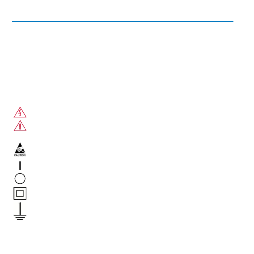
HIGH VOLTAGE, risk of electric shock.
CAUTION of potential for damage to probe or instrument it is connected to or WARNING
of potential bodily injury. Attend to the accompanying information to protect against
personal injury or damage. Do not proceed until conditions are fully understood and met.
ELECTROSTATIC DISCHARGE (ESD) HAZARD. The probe is susceptible to damage if antistatic measures are not taken.
ON (POWER)
OFF (POWER)
DOUBLE INSULATION
MEASUREMENT GROUND TERMINAL
Safety Instructions
This section contains instructions that must be observed to keep this oscilloscope accessory
operating in a correct and safe condition. You are required to follow generally accepted
safety procedures in addition to the precautions specified in this section. The overall safety
of any system incorporating this accessory is the responsibility of the assembler of the
system.
Symbols
These symbols may appear on the probe body or in this manual to alert you to important
safety considerations.
2 923064-00 Rev A
Page 5

Operator’s Manual
Precautions
To avoid personal injury or damage to property, review and comply with the following
safety precautions.
Use product only as specified. The probe is designed to make differential voltage
measurements. It is not to be used to insulate the circuit under test from the measuring
instrument.
Do not overload. To avoid electric shock or fire hazard, do not apply any potential that
exceeds the maximum rating of the probe and/or the probe accessory (e.g. probe hooks),
whichever is less.
Connect and disconnect properly. To avoid electric shock or fire hazard, always make the
connections from the probe input leads to the probe hooks before making any connections
to a voltage source. Do not connect or disconnect probe hooks to a votage source unless
they are first connected to the probe input leads. Ensure connections between probe input
leads and probe hooks are secure before connecting them to a voltage source.
Use only accessories compatible with the probe. Use only accessories that are shipped
with the product. Substitution of other accessories may create a potential shock hazard.
Comply with voltage derating curve. When measuring higher frequency signals, comply
with the Voltage vs. Frequency Derating Curve (see Page 7).
Observe all terminal ratings. To avoid electric shock or fire, do not use the probe above the
input limits shown on the probe as well as all accessories.
Do not remove probe casing. Removing the probe’s case or touching exposed connections
may result in electric shock.
Use only within operational environment listed. Do not use in wet or explosive
atmospheres. Keep product surfaces clean and dry.
923064-00 Rev A 3
Page 6

AP031 Probe
Avoid damage to cable through excessive bending.
Handle with care. Tips of probe hooks are sharp. They puncture skin or cause other bodily
injury if not handled properly.
Keep fingers behind the finger guard of the probe hooks.
Do not operate with suspected failures. Before each use, inspect the probe and probe
hooks for any potential damage such as tears or other defects in the probe body, cable
jacket, accessories, etc. If any part is damaged, cease operation immediately and sequester
the probe from inadvertent use.
Introduction
The AP031 is a fully differential active probe designed for applications where electrical
signals must be measured relative to a floating voltage different to the oscilloscope ground
potential.
This probe is specifically designed for situations where:
The reference voltage may be several hundreds volts above or below ground.
Measurements require the rejection of common mode signals.
Ground loops and currents produce to excessive signal interference.
The use of the probe ensures safe operation of the oscilloscope and maintains high signal
fidelity with good common mode rejection and dynamic range.
The probe is a fully differential active device. The differential capability allows
measurements to be made between two points in a circuit without reference to ground.
The two input signals are processed inside the probe (see figure 1) and the resulting singleended signal may be measured by any grounded oscilloscope. Because the differential
4 923064-00 Rev A
Page 7

Operator’s Manual
voltage is calculated within the probe, with only the resultant difference signal being passed
to the oscilloscope, a large dynamic range can be achieved with excellent rejection of
common mode signals.
Figure 1
923064-00 Rev A 5
Page 8

AP031 Probe
Bandwidth
25 MHz
Rise Time
14 ns
Attenuation
1:10 / 1:100
Atten. Accuracy
±2 %
Input Resistance
4 MΩ
Input Capacitance
5.5 pF each side to ground
Input Configuration
Differential
Input Voltage
Max. Differential 1:100 Range
±700 V (DC + AC pk) and 700 V r.m.s.
Max. Differential 1:10 Range
±70 V (DC + AC pk) and 70 V r.m.s.
Max. Common Mode
±700 V ( DC + AC pk) and 700 V r.m.s.
Max. Absolute
±1400 V ( DC + AC pk) and 1000 V r.m.s.
CMRR
50 Hz - 80 dB
20 kHz - 60 dB
Output Offset (Typical)
<±5 mV
Output Noise (Typical)
0.7 mV r.m.s typical
Specifications
Electrical Characteristics
6 923064-00 Rev A
Page 9

Operator’s Manual
Electrical Ratings
Maximum Input Voltage 1000 V rms (1400 V DC + peak AC)
Installation (Overvoltage) Category III
Pollution Degree 2
Measurement Category III (CAT III) is applicable for measurements performed in the building installation.
Pollution Degree 2 is applicable to an operating environment where normally only dry non-conductive pollution
occurs. Occasionally a temporary conductivity caused by condensation must be expected.
General Characteristics
Operating Temperature -10º C to 40º C
Storage Temperature -30º C to 70º C
Altitude, Operating up to 2000 m (6560 ft)
Cable Length 1.3 m
Weight (probe only) 42 g
Power requirement Four internal 1.5 V AA size batteries or
6 V d.c. / 60 mA mains adaptor
(Not supplied )
Dimensions 6.6" (168 mm) x 2.4" (62 mm) x 0.79" (20 mm)
(excluding casing )
Cables BNC, 95 cm ( RG58 / U ), Input Lines: 45 cm
(PVC, double insulation )
Accessories 2 x Safety Hooks, 4 mm compatible (1 red, 1 black)
Weight 9.35 oz ( 285 g ) excluding batteries and casing
Safety Certification EN61010-1:2010 ; EN61010-031/A1:2008
1000V CAT III Approval
923064-00 Rev A 7
Page 10

AP031 Probe
Voltage vs. Frequency Derating
NOTE: The voltage vs frequency derating curve provides the maximum voltage that can
be applied to the probe inputs without risking damage to the probe or injury to the user
from possible burns at higher frequencies.
WARNING. To avoid risk of electric shock or fire, do not exceed either the voltage
rating or category rating of the probe or the probe hook, whichever is the lesser of
the two.
WARNING. To avoid risk of electric shock when using the probe or accessories,
keep your fingers behind the finger guard of the probe hook.
8 923064-00 Rev A
Page 11

Operator’s Manual
Range Setting
Probe Operating Range (DC + Peak AC)
1/10
± 70 V
1/100
± 700 V
Making Measurements
Ensure the probe is fitted with four high-quality, AA cells. These should be cells that are
protected from leakage which could damage the power supply contacts in the probes.
Before making any measurements or connections refer to the safety information contained
in this document.
Connect the probe to one of the oscilloscope input channels ensuring the BNC connector is
fully mated, and the safety ground lead to the oscilloscope CAL BNC connection.
Select the proper range setting on the probe using the slide-switch on the probe body.
Adjust the input coupling impedance and attenuation of the oscilloscope channel to which
the probe is connected using the Probe tab of the Channel (Vertical) setup dialog.
Ensure 1 M input impedance ( ‘DC1M’ or ‘AC1M’ ) is selected. The use of 50 input
impedance will unduly load the output of the differential probe resulting in reduced
amplitude output and incorrect scaling.
To ensure the oscilloscope correctly interprets the vertical waveform scale be sure to adjust
the probe attenuation setting using the ‘Probe Atten’ menu controls. The example shown,
x100 probe attenuation, would achieve correct vertical scaling AP031 operating with a
maximum range of ± 700 V.
Finally, adjust the vertical sensitivity and offset of the oscilloscope channel to which the
probe is connected to achieve an optimum display.
923064-00 Rev A 9
Page 12

AP031 Probe
Maintenance
Cleaning
Clean the exterior of the probe only with a soft cloth moistened with either water or
isopropyl alcohol.
Service Strategy
The AP031 series probes utilize fine-pitch surface mount devices. It is, therefore, impractical
to attempt repair in the field. Defective probes must be returned to a Teledyne LeCroy
service facility for diagnosis and exchange. A defective probe under warranty will be
replaced with a factory refurbished probe. A probe that is not under warranty can be
exchanged for a factory refurbished probe for a modest fee. You must return the defective
probe in order to receive credit for the probe core.
WARNING No user serviceable components inside. Do not remove covers. Refer
servicing to qualified personnel.
10 923064-00 Rev A
Page 13

Operator’s Manual
Certifications
This section certifies the AP031 probe’s Electromagnetic Compatibility (EMC), Safety and
Environmental compliances.
EMC Compliance
EC Declaration of Conformity - EMC
The probe meets intent of EC Directive 2004/108/EC for Electromagnetic Compatibility.
Compliance was demonstrated to the following specifications as listed in the Official Journal
of the European Communities:
EN 61326-1:2006, EN 61326-2-1:2006 EMC requirements for electrical equipment for
measurement, control, and laboratory use.
Electromagnetic Emissions:
CISPR 11:2003, Radiated and Conducted Emissions Group 1, Class A
1 2
Electromagnetic Immunity:
EN 61000-4-2:2001 Electrostatic Discharge, 4 kV contact, 8 kV air, 4 kV vertical/horizontal
coupling planes 3
EN 61000-4-3:2006 RF Radiated Electromagnetic Field, 3 V/m, 80-1000 MHz; 3 V/m, 1400
MHz - 2 GHz; 1 V/m, 2 GHz - 2.7 GHz 3
1 Emissions which exceed the levels required by this standard may occur when the probe is connected to a test
object.
2 This product is intended for use in nonresidential areas only. Use in residential areas may cause electromagnetic
interference.
3 Meets Performance Criteria “B” limits of the respective standard: during the disturbance, product undergoes a
temporary degradation or loss of function or performance which is self-recoverable.
923064-00 Rev A 11
Page 14

AP031 Probe
Vicom Australia Ltd.
1064 Centre Road
Oakleigh, South Victoria 3167
Australia
Vicom New Zealand Ltd.
60 Grafton Road
Auckland
New Zealand
European Contact:
Teledyne LeCroy Europe GmbH
Waldhofer Str 104
D-69123 Heidelberg
Germany
Tel: (49) 6221 82700
Australia & New Zealand Declaration of Conformity—EMC
The Probe complies with the EMC provision of the Radio Communications Act per the
following standards, in accordance with requirements imposed by Australian
Communication and Media Authority (ACMA):
CISPR 11:2003 Radiated and Conducted Emissions, Group 1, Class A, in accordance with
EN61326-1:2006 and EN61326-2-1:2006.
Australia / New Zealand Contacts:
12 923064-00 Rev A
Page 15

Operator’s Manual
Safety Compliance
EC Declaration of Conformity – Low Voltage
The probe meets intent of EC Directive 2006/95/EC for Product Safety. Compliance was
demonstrated to the following specifications as listed in the Official Journal of the European
Communities:
EN 61010-1:2010 Safety requirements for electrical equipment for measurement, control,
and laboratory use – Part 1: General requirements
EN 61010-2:030:2010 Safety requirements for electrical equipment for measurement,
control, and laboratory use – Part 2-030: Particular requirements for testing and measuring
circuits
EN 61010-031/A1:2008 Safety requirements for electrical equipment for measurement,
control, and laboratory use – Part 031: Safety requirements for hand-held probe assemblies
for electrical measurement and test.
Measurement Category III (CAT III), for measurements performed in the building
installation.
Measurement Category II (CAT II), for measurements performed on circuits directly
connected to the low-voltage installation.
Pollution Degree 2, operating environment where normally only dry non-
conductive pollution occurs. Conductivity caused by temporary condensation
should be expected.
923064-00 Rev A 13
Page 16

AP031 Probe
Environmental Compliance
End-Of-Life Handling
The probe is marked with this symbol to indicate that it complies with the
applicable European Union requirements to Directives 2002/96/EC and
2006/66/EC on Waste Electrical and Electronic Equipment (WEEE) and
Batteries.
The probe is subject to disposal and recycling regulations that vary by
country and region. Many countries prohibit the disposal of waste electronic
equipment in standard waste receptacles. For more information about
proper disposal and recycling of your Teledyne LeCroy product, please visit
teledynelecroy.com/recycle.
Restriction of Hazardous Substances (RoHS)
This probe has been classified as Industrial Monitoring and Control Equipment, and is
outside the scope of the 2011/65/EU RoHS Directive until 22 July 2017 (per Article 4,
Paragraph 3).
14 923064-00 Rev A
Page 17

Contact Teledyne LeCroy
Teledyne LeCroy Service Centers
United States and Canada -
World Wide Corporate Office
Teledyne LeCroy Corporation
700 Chestnut Ridge Road
Chestnut Ridge, NY, 10977-6499, USA
Ph: 800-553-2769 / 845-425-2000
FAX: 845-578-5985
teledynelecroy.com
Support:
contact.corp@teledynelecroy.com
Sales:
customersupport@teledynelecroy.com
United States - Protocol Solutions Group
Teledyne LeCroy Corporation
3385 Scott Boulevard
Santa Clara, CA, 95054, USA
FAX: 408-727-0800
teledynelecroy.com
Sales and Service:
Ph: 800-909-7211 / 408-727-6600
contact.corp@teledynelecroy.com
Support:
Ph: 800-909-7112 / 408-653-1260
psgsupport@teledynelecroy.com
European Headquarters
Teledyne LeCroy SA
4, Rue Moïse Marcinhes
Case postale 341
1217 Meyrin 1
Geneva, Switzerland
Ph: + 41 22 719 2228 / 2323 /2277
FAX:+41 22 719 2233
contact.sa@teledynelecroy.com
applications.indirect@teledynelecroy.com
teledynelecroy.com/europe
Protocol Analyzers:
Ph: +44 12 765 03971
Singapore, Oscillosocpes
Teledyne LeCroy Singapore Pte Ltd.
Blk 750C Chai Chee Road #02-08
Technopark @ Chai Chee
Singapore 469003
Ph: ++ 65 64424880
FAX: ++ 65 64427811
Singapore, Protocol Analyzers
Genetron Singapore Pte Ltd.
37 Kallang Pudding Road, #08-08
Tong Lee Building Block B
Singapore 349315
Ph: ++ 65 9760-4682
923064-00 Rev A 15
Operator’s Manual
Page 18

AP031 Probe
Teledyne LeCroy Service Centers
China
Teledyne LeCroy Corporation Beijing
Rm. 2001 - Office; Rm. 2002 - Service Center
Unit A, Horizon Plaza
No. 6, Zhichun Road, Haidian District
Beijing 100088, China
Ph: ++86 10 8280 0318 / 0319 / 0320
FAX:++86 10 8280 0316
Service:
Rm. 2002
Ph: ++86 10 8280 0245
Korea
Teledyne LeCroy Korea
10th fl.Ildong Bldg.
968-5 Daechi-dong, Gangnam-gu
Seoul 135-280, Korea
Ph: ++ 82 2 3452 0400
FAX: ++ 82 2 3452 0490
Taiwan
LeColn Technology Co Ltd.
Far East Century Park, C3, 9F
No. 2, Chien-8th Road,
Chung-Ho Dist., New Taipei City, Taiwan
Ph: ++ 886 2 8226 1366
FAX: ++ 886 2 8226 1368
Japan
Teledyne LeCroy Japan
Hobunsya Funchu Bldg, 3F
3-11-5, Midori-cho, Fuchu-Shi
Tokyo 183-0006, Japan
Ph: ++ 81 4 2402 9400
FAX: ++ 81 4 2402 9586
teledynelecroy.com/japan
16 923064-00 Rev A
Page 19

Page 20

 Loading...