

Page 1
Operator’s
Manual
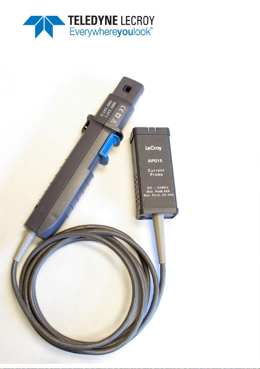
AP015
Current Probe
i
Page 2

Page 3

AP015 Current Probe
Operator’s Manual
October 2013
iii
Page 4

700 Chestnut Ridge Road
Chestnut Ridge, NY, 10977-6499
Tel: (845) 425-2000
Fax: (845) 578 5985
teledynelecroy.com
© 2013 Teledyne LeCroy, Inc. All rights reserved.
Unauthorized duplication of Teledyne LeCroy documentation materials other than for internal
sales and distribution purposes is strictly prohibited. However, clients are encouraged to distribute
and duplicate Teledyne LeCroy documentation for their own internal educational purposes.
Teledyne LeCroy is a registered trademark of Teledyne LeCroy, Inc. Windows is a registered
trademark of Microsoft Corporation. Other product or brand names are trademarks or requested
trademarks of their respective holders. Information in this publication supersedes all earlier
versions. Specifications are subject to change without notice.
Warranty
Teledyne LeCroy warrants this oscilloscope accessory for normal use and operation within
specification for a period of one year from the date of shipment. Spare parts, replacement parts
and repairs are warranted for 90 days.
In exercising its warranty, Teledyne LeCroy, at its option, will either repair or replace any assembly
returned within its warranty period to the Customer Service Department or an authorized service
center. However, this will be done only if the product is determined by Teledyne LeCroy’s
examination to be defective due to workmanship or materials, and the defect is not caused by
misuse, neglect, accident, abnormal conditions of operation, or damage resulting from attempted
repair or modifications by a non-authorized service facility.
The customer will be responsible for the transportation and insurance charges for the return of
products to the service facility. Teledyne LeCroy will return all products under warranty with
transportation charges prepaid.
This warranty replaces all other warranties, expressed or implied, including but not limited to any
implied warranty of merchantability, fitness or adequacy for any particular purposes or use.
Teledyne LeCroy shall not be liable for any special, incidental, or consequential damages, whether
in contract or otherwise.
922254-00 Rev A
October 2013
Page 5
Operator’s Manual
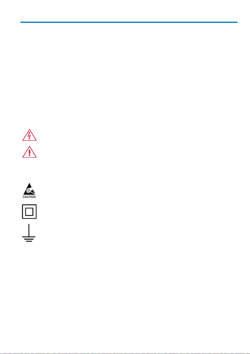
WARNING. High Voltage, risk of electric shock.
CAUTION. Potential for damage to probe or instrument it is connected
to. Attend to the accompanying information to protect against
personal injury or damage. Do not proceed until conditions are fully
understood and met.
ELECTROSTATIC DISCHARGE (ESD) HAZARD. The probe is susceptible
to damage if anti-static measures are not taken.
DOUBLE INSULATION
PROTECTIVE (EARTH) TERMINAL
Safety Instructions
This section contains instructions that must be observed to keep this
oscilloscope accessory operating in a correct and safe condition. You are
required to follow generally accepted safety procedures in addition to the
precautions specified in this section. The overall safety of any system
incorporating this accessory is the responsibility of the assembler of
the system.
Symbols
These symbols may appear on the probe body or in this manual to alert you to
important safety considerations.
Precautions
To avoid personal injury or damage to property, review and comply with the
following safety precautions.
Use product only as specified. Use of the probe is restricted to insulated
conductors or limited energy circuit conductors.
Connect and disconnect properly. Connect probe to the measurement
instrument before making any connections to a voltage/current source.
922254-00 Rev A 1
Page 6

ADP015 Current Probe
WARNING. To avoid risk of electric shock, keep your fingers behind
the finger guard when locking and unlocking the probe slider. Keep
the probe cable away from the circuits being measured. Use only the
specified accessories.
WARNING. The probe is classified as a Type D current sensor per
EN61010-032 safety standard. Use of the probe is restricted to
insulated conductors or limited energy circuit conductors. Any use of
the probe in a manner not specified by the manufacturer may impair
the probe’s safety protection.
Observe all terminal ratings. To avoid electric shock or fire, do not use the
probe above the current & voltage limits shown on the probe as well as all
accessories.
Do not remove probe casing. Removing the probe’s case or touching exposed
connections may result in electric shock.
Use indoors only.
Use only within operational environment listed. Do not use in wet or explosive
atmospheres.
Keep product surfaces clean and dry. Clean with a cloth moistened in water or
alcohol. Do not submerge instrument. Do not use harsh or abrasive cleansers.
Do not operate with suspected failures. Do not use the probe if any part is
damaged. Cease operation immediately and sequester the probe from
inadvertent use.
Operating Environment
The accessory is intended for indoor use and should be operated in a clean, dry
environment. Before using this product, ensure that its operating environment is
maintained within these parameters:
Temperature: 0 to 40 °C
Humidity: 80% maximum up to 31 °C
Altitude: 2000 m maximum
2 922254-00 Rev A
Page 7

Operator’s Manual
Specifications
The following specifications are valid for model AP015 current probes after the
probe has reached operating temperature, which is 20 minutes with power
applied in a environment with stable ambient temperature. The probe must be
operating within the environmental conditions listed in the General
Characteristics section, and has been calibrated within the past 12 months in an
ambient temperature of 23 ±5 °C.
Nominal Characteristics
Nominal characteristics describe parameters and attributes which are
guaranteed by design, but do not have associated tolerances.
Interface: ProBus
Coupling: AC, GND, DC
Maximum Current: DC ±30 A (continuous)
±50 A maximum (< 10 s)
Sensitivity: 10 mA/div to 20 A/div
Offset Range: ±100 A maximum
Maximum Conductor Size: 5 mm
Maximum Voltage 300 V CAT I
(bare conductor): 150 V CAT II
Cable Length: 2 m
Weight (probe only): 300 g (10.6 oz.)
Warranted Electrical Characteristics
Warranted characteristics describe parameters which have guaranteed
performance. Unless otherwise noted, tests are provided in the Performance
Verification Procedure for all warranted specifications.
DC Accuracy: ±1% of reading to 15 A
(at 25 °C, after degauss)
±2% of reading to 30 A
(at 25 °C, after degauss)
Bandwidth: DC to 50 MHz
922254-00 Rev A 3
Page 8

ADP015 Current Probe
Typical Electrical Characteristics
Typical characteristics describe parameters which do not have guaranteed
performance, however are representative of the average performance from a
sample of several probes. Tests for typical characteristics are not provided in the
Performance Verification Procedure.
Rise Time: < 7 ns
Slew Rate: > 1.6 A/ns (sensitivity ≥ 1 A/div)
Insertion Impedance: < 0.06 Ω at 5 MHz
Performance Verification
This procedure can be used to verify the warranted characteristics of the AP015
Current Probe.
The recommended calibration interval for the model AP015 Current Probe is one
year. The complete performance verification procedure should be performed as
the first step of annual calibration. Performance verification can be completed
without removing the instrument covers or exposing the user to hazardous
voltages. Test results can be recorded on a photocopy of the Test Record
provided at the end of this manual.
Adjustment should only be attempted if a parameter measured in the
Performance Verification Procedure is outside of the specification limits.
Adjustment should only be performed by qualified personnel.
Required Equipment
The following table lists the test equipment and accessories, or their equivalents,
that are required for performance verification of the AP015 Current Probe.
Because the input and output connector types may vary on different brands and
models of test instruments, additional adapters or cables may be required.
4 922254-00 Rev A
Page 9

Operator’s Manual
Description
Minimum Requirements
Test Equipment Examples
Wide Band oscilloscope
Minimum 200 MHz bandwidth
ProBus interface equipped
Software Version 7.6.0 or
greater
Teledyne LeCroy LT322
Teledyne LeCroy X-Stream
scope with AP-1M Hi-Z
adapter
Digital Multimeter
(2 required)
DC: 0.1% accuracy 5.5 digit
resolution with Null capability
(referenced measurements)
Agilent Technologies 34401A
Fluke 8842A-09
Keithley 2001
Leveled Sine Wave
Generator
Relative output level accurate
to ±0.3 dB into 50 Ω
1 to 100 MHz frequency
range Output adjustable to 18
dBm
Tegam SG503 with TM
series mainframe and
matching output cable.
A semiautomatic software
leveled signal source
calibrated with a power
meter may be substituted.
DC Power Supply
Output adjustable to > 6 V at
1 A
Agilent Technologies
E3610A
Calibration Fixture,
50 Turn Loop
50 Turn loop in series with 0.5
Ω ±0.2% resistor with sense
terminals
Teledyne LeCroy CP015CF02
Calibration Fixture,
High Speed Shunt
50 Ω Termination into single
turn loop.
VSWR < 1.25: 1 DC – 50
MHz
Teledyne LeCroy CP015CF01
Calibration Fixture
ProBus Extension Cable
Teledyne LeCroy PROBUSCF01
BNC Adapter, T
Male-to-Dual-Female
Pomona 3285
BNC coaxial cable
Male-Male BNC, 50 Ω, 36”
Pomona 5697-36
Banana Plug adapter
BNC Female-to-Banana Plug
Pomona 1269
Patch Cables
(4 required)
Male Banana-to-Male
Banana, 12”
Pomona B-12-0 (black)
Pomona B-12-2 (red)
Table 1. List of Required Equipment
922254-00 Rev A 5
Page 10

ADP015 Current Probe
Preliminary Procedure
1. Connect the AP015 to the channel 1 input of the oscilloscope, and
completely close the probe slider.
2. Turn the oscilloscope on and allow at least 30 minutes warm-up time for
the AP015 and test equipment before performing the Verification
Procedure.
3. Turn on the other test equipment and allow these to warm up for the
time recommended by the manufacturer.
4. While the instruments are reaching operating temperature, make a
photocopy of the Performance Verification Test Record (located at the
back of this manual) and fill in the necessary data.
Functional Check
The functional check will verify the basic operation of all probe functions. It is
recommend that the Functional Check be performed prior the Performance
Verification Procedure.
1. For LT series scopes, select Channel 1, select the Coupling menu, and
verify that Global BWL is set to OFF.
2. Verify that Probe sensed (AP015) is displayed.
3. Unlock the slider on the probe by pushing the lever towards the probe
cable. Release the lever so that the input slider remains closed, but
unlocked.
4. Verify that the message: Warning: AP015 Probe Unlocked… is displayed
at the top of the screen.
5. Lock the probe slider by pushing fully away from the probe cable.
6. Verify that the warning message disappears.
7. Degauss the probe by pressing the DEGAUSS button, (located in the
Coupling menu), twice.
8. Verify that no error message remains displayed at the top of the screen.
6 922254-00 Rev A
Page 11

Operator’s Manual
Performance Verification Procedure
The warranted characteristics of the AP015 Current Probe are valid at any
temperature within the Environmental Characteristics listed in the
Specifications. However, some of the other test equipment used to verify the
performance may have environmental limitations required to meet the accuracy
needed for the procedure. Make sure that the ambient conditions meet the
requirements of all the test instruments used in this procedure.
NOTE: The correct operation of the controls of the AP015 requires oscilloscope
software version 7.6.0 or higher for LT series scopes. The use of earlier versions
is not recommended. The software version in the LT series test oscilloscope can
be verified by pushing SHOW STATUS, then selecting the System menu option.
Contact your local Teledyne LeCroy representative if the software in your
oscilloscope requires updating.
A. Check Bandwidth
1. Set the Leveled Sine Wave Generator frequency to 50 kHz, the output
level to approximately 5 Vp-p (+18 dBm), and turn RF ON.
2. Connect the output to the BNC connection of the high-speed shunt
calibration fixture, AP015-CF02, using the matched BNC coaxial cable
specified for use with the leveled sine wave generator.
3. Open the slider and connect the AP015 to the high-speed shunt
calibration fixture. Close and lock the probe slider by pushing it fully
away from the probe cable.
4. Push the AUTO SETUP button on the oscilloscope. Press MEASURE
TOOLS, set the mode to Std Voltage, on trace 1, from 0.00 div to 10.00
div.
5. Adjust the generator level until the current is 100 mA peak-to-peak, as
measured using the peak-to-peak function on the oscilloscope.
6. Set the sine wave generator frequency to 25 MHz. Be careful not to alter
the signal amplitude.
7. Slowly increase the output frequency until the displayed amplitude of
the current sine wave decreases to 71 mA peak-to-peak (a 3 dB
reduction in amplitude).
922254-00 Rev A 7
Page 12

ADP015 Current Probe
8. Check that this frequency is greater than 50 MHz, and record the
frequency on the test record.
B. Check DC Accuracy
1. Set the DC Power Supply output voltage to approximately 0 V.
2. Remove the AP015 from the oscilloscope, and reconnect using the
ProBus extension cable. Install a BNC T connector, BNC cable, and BNC
to dual banana plug adapter as shown in the figure on the following
page. Connect the dual banana plug adapter into one of the digital
multimeters.
3. Using banana patch cords, connect the 'V Source' terminal of the 50
Turn Calibration Loop, AP015-CF01, to the positive output of the power
supply. Connect the 'V Return' terminal to the power supply negative
terminal. (Refer to Figure 1, DC Accuracy Test Set Up.)
4. Connect the Current Sense terminals of the 50 Turn Calibration Loop to
the voltage inputs of the second digital multimeter.
Figure 1, DC Accuracy Test Set Up
5. With the AP015 removed from any signal and the slider returned to the
LOCKED position, degauss the probe by pressing the DEGAUSS button
(located in the Coupling menu) twice.
8 922254-00 Rev A
Page 13

Operator’s Manual
6. Open the AP015 slider and position the probe input around the 50 Turn
loop. Close and LOCK the slider.
7. Set the oscilloscope channel vertical scale to 20 A/div.
8. With the power supply set to 0 V, press the 'Null' button of the
multimeter measuring the probe voltage to subtract the probe's offset
voltage from the measurement. (If the multimeter being used does not
have this capability, the offset value can be manually subtracted from
the probe output values recorded below.)
9. Increase the power supply voltage until the voltage measured at the
'Current Sense' terminals (DMM #2) is approximately 150 mV. (This
corresponds to 15 A at the probe head).
10. Record the exact value (a) of the current sense voltage measured with
DMM #2 on the test record line marked '15 A Current Sense,' and (b) the
probe output voltage measured with DMM #1 on the line marked '15 A
Probe Output.'
11. Multiply the value recorded for '15 A Current Sense' by 10, and record
this value on the line labeled '15 A Current'.
12. Calculate the percentage difference between the probe output voltage
and the actual current using the equation 100 * (b - c)/c. Record this
value on the line marked '15 A Accuracy.'
13. Verify that the 15 A Accuracy is < ±1%.
14. Increase the power supply voltage until the voltage measured at the
'Current Sense' terminals is approximately 300 mV. (This corresponds to
30 A at the probe head).
15. Record the exact value (d) of the current sense voltage on the test
record line marked '30 A Current Sense,' and (e) the probe output
voltage on the line marked '30 A Probe Output.'
16. Multiply the value recorded for '30 A Current Sense' by 10, and record
this value on the line labeled '30 A Current.'
17. Calculate the percentage difference between the probe output voltage
and the actual current using the equation 100 * (e - f)/f. Record this
value on the line marked '30 A Accuracy.'
922254-00 Rev A 9
Page 14

ADP015 Current Probe
CAUTION. This test increases the power dissipated inside the probe. Do
not leave the increased current turned on longer than needed to
complete the test (10 seconds.
18. Verify that the 30 A Accuracy is < ±2%.
19. Leave the connection set up for the remaining test.
C. Check Peak Current
1. Increase the power supply voltage until the voltage measured at the
'Current Sense' terminals is > 500 mV. (This corresponds to > 50 A at the
probe head.)
2. Note the probe output voltage. Verify that the voltage remains stable
without significant decrease for 10 seconds before shutting the current
off. Record the value on the line marked '50 A DC Current' on the test
record.
This completes the Performance Verification of the AP015. Complete and file the
results recorded in the AP015 Performance Verification Test Record as required
by your quality procedures. Apply a suitable calibration label to the AP015
housing as required.
Adjustment Procedure
This procedure can be used to adjust the AP015 Current Probe in order to meet
the warranted gain specification. The other parameters verified in the
Performance Verification procedure do not have adjustments associated with
them. This procedure should only be performed if the instrument fails to meet
the Performance Verification tests. If the probe cannot be adjusted to meet the
Performance Verification limits, repair may be necessary.
To ensure instrument accuracy, check the calibration of the AP015 every year.
Before calibration, thoroughly clean and inspect this unit.
Adequate guard bands were designed into this instrument to assure it will meet
or exceed published specifications over the entire operating temperature range.
To continue to meet the environmental specifications, all adjustments must be
performed in a controlled environment with an ambient temperature of
25 ±5° C. The instrument must also be at stable operating temperature before
performing adjustments.
10 922254-00 Rev A
Page 15

Operator’s Manual
CAUTION. The adjustment procedure requires removal of the
instrument covers. These covers are part of the ESD protection system
of the AP015. To protect the instrument, the entire procedure should
be performed on a static dissipating work surface only. The technician
should wear an antistatic grounding wrist strap and follow standard
static control procedures.
CAUTION. The compensation box cover serves to align the
ProBus connector pins during mating. With the cover
removed, care must be used to assure correct alignment of
the connector pins. Applying power with the pin alignment
incorrect may damage the probe.
Test Equipment Required
The adjustment procedure requires a subset of the equipment required for
Performance Verification. Refer to Table 1 located in the Performance
Verification procedure.
If alternate test equipment is substituted, control settings or calibration
equipment setups may need to be altered. Alternate models of test equipment
may have different connector styles requiring adapters not included in the
equipment list.
Preliminary Procedure
1. Remove the two screws that secure the plastic cover on the cable end of
the ProBus interface housing. Gently pull on the probe cable to slide the
circuit board assembly from the metal housing.
2. Connect the AP015 (without the compensation box cover ) to the
oscilloscope using the setup for the DC Accuracy check in the
Performance Verification Procedure. (Refer to Figure 1 in the
Performance Verification section).
3. Turn on the oscilloscope power switch to allow the probe to warm up at
least 20 minutes before proceeding with the gain adjustment.
922254-00 Rev A 11
Page 16

ADP015 Current Probe
Adjust R24, Gain
1. With the AP015 Current Probe removed from any signal and the slider
returned to the LOCKED position, degauss the probe by pressing the
DEGAUSS button (located on the coupling menu) twice.
2. Connect the AP015 to the 50 Turn loop, and set the oscilloscope vertical
scale to 20 A/div.
3. With the power supply set to 0 V, press the 'Null' button of the
multimeter measuring the probe voltage to subtract the probe's offset
voltage from the measurement. (If the multimeter being used does not
have this capability, the offset value can be manually subtracted from
the probe output values measured).
4. Increase the power supply voltage until the voltage measured at the
'Current Sense' terminals is approximately 100 mV. (This corresponds to
10 A at the probe head).
5. Carefully adjust R24 until the value measured by the multimeter
measuring the probe output is equal to 10x the value measured by the
current sense meter. (There are two adjustments on the circuit board;
R24 is the one farther from the board edge).
Figure 2, Gain Adjustment Location
6. After adjustment, calculate the accuracy (as in steps 15, 16, and 17
above) to confirm that the probe is measuring better than 1% accuracy.
7. Insert and tighten the two screws that secure the end panel to the
ProBus interface housing. Avoid over tightening the screws, as the cover
may warp.
8. Repeat the Performance Verification procedure to ensure compliance
with the warranted specifications.
12 922254-00 Rev A
Page 17

Operator’s Manual
Certifications
EMC Compliance
EC DECLARATION OF CONFORMITY - EMC
The probe meets intent of EC Directive 2004/108/EC for Electromagnetic Compatibility.
Compliance was demonstrated to the following specifications as listed in the Official
Journal of the European Communities:
EN 61326-1:2006, EN 61326-2-1:2006 EMC requirements for electrical equipment for
measurement, control, and laboratory use.
Electromagnetic Emissions:
CISPR 11:2003, Radiated and Conducted Emissions Group 1, Class A
Electromagnetic Immunity:
1 2
EN 61000-4-2:2001 Electrostatic Discharge, 4 kV contact, 8 kV air, 4 kV
vertical/horizontal coupling planes 3
EN 61000-4-3:2006 RF Radiated Electromagnetic Field, 3 V/m, 80-1000 MHz; 3 V/m,
1400 MHz - 2 GHz; 1 V/m, 2 GHz - 2.7 GHz 3
1 Emissions which exceed the levels required by this standard may occur when the probe is
connected to a test object.
2 This product is intended for use in nonresidential areas only. Use in residential areas may cause
electromagnetic interference.
3 Meets Performance Criteria “B” limits of the respective standard: during the disturbance,
product undergoes a temporary degradation or loss of function or performance which is selfrecoverable.
European Contact:
Teledyne LeCroy Europe GmbH
Waldhofer Str 104
D-69123 Heidelberg
Germany
Tel: (49) 6221 82700
AUSTRALIA & NEW ZEALAND DECLARATION OF CONFORMITY—EMC
Probe complies with the EMC provision of the Radio Communications Act per the
following standards, in accordance with requirements imposed by Australian
Communication and Media Authority (ACMA):
CISPR 11:2003 Radiated and Conducted Emissions, Group 1, Class A, in accordance with
EN61326-1:2006 and EN61326-2-1:2006.
922254-00 Rev A 13
Page 18

ADP015 Current Probe
Vicom Australia Ltd.
1064 Centre Road
Oakleigh, South Victoria 3167
Australia
Vicom New Zealand Ltd.
60 Grafton Road
Auckland
New Zealand
Australia / New Zealand Contacts:
Safety Compliance
EC DECLARATION OF CONFORMITY – LOW VOLTAGE
The probe meets intent of EC Directive 2006/95/EC for Product Safety. Compliance was
demonstrated to the following specifications as listed in the Official Journal of the
European Communities:
EN 61010-1:2010 Safety requirements for electrical equipment for measurement,
control, and laboratory use – Part 1: General requirements
EN 61010-2:032:2012 Safety requirements for electrical equipment for measurement,
control, and laboratory use – Part 032: Particular requirements for hand-held and handmanipulated current sensors for electrical test and measurement
Environmental Compliance
END-OF-LIFE HANDLING
The probe is marked with this symbol to indicate that it complies with
the applicable European Union requirements to Directives 2002/96/EC
and 2006/66/EC on Waste Electrical and Electronic Equipment (WEEE)
and Batteries.
The probe is subject to disposal and recycling regulations that vary by
country and region. Many countries prohibit the disposal of waste
electronic equipment in standard waste receptacles. For more
information about proper disposal and recycling of your Teledyne LeCroy
product, please visit teledynelecroy.com/recycle.
RESTRICTION OF HAZARDOUS SUBSTANCES (ROHS)
The probe conforms to 2011/65/EU RoHS2 Directive based on the fact that it is classified
as Industrial Monitoring and Control Instrument (per Article 3, Paragraph 24) and these
product(s) & associated accessories are exempt from RoHS compliance until 22 July 2017
(per Article 4, Paragraph 3).
14 922254-00 Rev A
Page 19

Contact Teledyne LeCroy
Teledyne LeCroy Service Centers
United States and Canada -
World Wide Corporate Office
Teledyne LeCroy Corporation
700 Chestnut Ridge Road
Chestnut Ridge, NY, 10977-6499, USA
Ph: 800-553-2769 / 845-425-2000
FAX: 845-578-5985
teledynelecroy.com
Support:
contact.corp@teledynelecroy.com
Sales:
customersupport@teledynelecroy.com
United States - Protocol Solutions Group
Teledyne LeCroy Corporation
3385 Scott Boulevard
Santa Clara, CA, 95054, USA
FAX: 408-727-0800
teledynelecroy.com
Sales and Service:
Ph: 800-909-7211 / 408-727-6600
contact.corp@teledynelecroy.com
Support:
Ph: 800-909-7112 / 408-653-1260
psgsupport@teledynelecroy.com
European Headquarters
Teledyne LeCroy SA
4, Rue Moïse Marcinhes
Case postale 341
1217 Meyrin 1
Geneva, Switzerland
Ph: + 41 22 719 2228 / 2323 /2277
FAX:+41 22 719 2233
contact.sa@teledynelecroy.com
applications.indirect@teledynelecroy.com
teledynelecroy.com/europe
Protocol Analyzers:
Ph: +44 12 765 03971
Singapore, Oscillosocpes
Teledyne LeCroy Singapore Pte Ltd.
Blk 750C Chai Chee Road #02-08
Technopark @ Chai Chee
Singapore 469003
Ph: ++ 65 64424880
FAX: ++ 65 64427811
Singapore, Protocol Analyzers
Genetron Singapore Pte Ltd.
37 Kallang Pudding Road, #08-08
Tong Lee Building Block B
Singapore 349315
Ph: ++ 65 9760-4682
China
Teledyne LeCroy Corporation Beijing
Rm. 2001 - Office; Rm. 2002 - Service Center
Unit A, Horizon Plaza
No. 6, Zhichun Road, Haidian District
Beijing 100088, China
Ph: ++86 10 8280 0318 / 0319 / 0320
FAX:++86 10 8280 0316
Service:
Rm. 2002
Ph: ++86 10 8280 0245
Korea
Teledyne LeCroy Korea
10th fl.Ildong Bldg.
968-5 Daechi-dong, Gangnam-gu
Seoul 135-280, Korea
Ph: ++ 82 2 3452 0400
FAX: ++ 82 2 3452 0490
Taiwan
LeColn Technology Co Ltd.
Far East Century Park, C3, 9F
No. 2, Chien-8th Road,
Chung-Ho Dist., New Taipei City, Taiwan
Ph: ++ 886 2 8226 1366
FAX: ++ 886 2 8226 1368
Japan
Teledyne LeCroy Japan
Hobunsya Funchu Bldg, 3F
3-11-5, Midori-cho, Fuchu-Shi
Tokyo 183-0006, Japan
Ph: ++ 81 4 2402 9400
FAX: ++ 81 4 2402 9586
teledynelecroy.com/japan
Operator’s Manual
922254-00 Rev A 15
Page 20

ADP015 Current Probe
Appendix A: Performance Verification
Test Record
Permission is granted to photocopy this form and use it to record the results of
measurements made during the performance verification of the AP015 Current
Probe. File the completed record as required by applicable internal quality
procedures.
Each section of the test record corresponds to the parameters tested in the
performance verification procedure. The numbers preceding the individual data
records correspond to the steps in the procedure that require recording of data.
Results recorded in the right-most column, labeled “Test Result” are the actual
specification limit check. The test limits are included in all of these steps. Other
measurements and the results of intermediate calculations that support the limit
check are recorded in the center column labeled “Intermediate Data.”
Permission is granted to reproduce this page for the purpose of recording test
results.
16 922254-00 Rev A
Page 21

AP015 Test Record
Serial Number:
Asset or Tracking Number:
Date:
Technician:
MODEL
SERIAL NUMBER
CALIBRATION
DUE DATE
Digital Multimeter #1
Digital Multimeter #2
High frequency Sine
Wave Generator
Power Meter (If used to
level Sine Wave
Generator)
Test Date:
S/N: ID#:
Technician:
Temp:
Humidity:
Before
Results
After Results
Equipment Used
Operator’s Manual
NOTES:
Comments:
922254-00 Rev A 17
Page 22

ADP015 Current Probe
Step
Description
Intermediate Data
Test Result
Bandwidth:
A-8
Probe Bandwidth (> 50 MHz)
___________MHz
DC Accuracy:
B-10a
15 A Current Sense (a)
___________V
B-10b
15 A Probe Output (b)
___________V
B-11
15 A Current (c)
___________A
B-12
15 A Accuracy (< ±1%)
___________%
B-15a
30 A Current Sense (d)
___________V
B-15b
30 A Probe Output (e)
___________V
B-16
30 A Current (f)
___________A
B-17
30 A Accuracy (< ±2%)
___________%
Peak Current:
C-2
50 A DC Current (> 10 s)
___________s
Results
18 922254-00 Rev A
Page 23

Page 24

 Loading...