

Teledyne ADFM Pro20, ADFM Analog Output Module, ADFM Hot Tap Technical Manual
ADFM
Acoustic Doppler Flow Meter
TECHNICAL MANUAL
This manual includes information for the following products:
ADFM Analog Output Module
Teledyne Isco P/N 69-7103-001
January 2000
ADFM Pro20
ADFM Hot Tap


ADFM Velocity Profiler
Technical Manual
January 2000
NOTE. This manual applies to ADFM firmware version 6.37 or higher. When newer firmware
versions are released, some commands may be modified or added. Read the README file on
the upgrade disk or check MGD’s web site for the latest changes.
IMPORTANT NOTICE
MGD Technologies Inc. was acquired as a subsidiary of Teledyne Isco Inc. in December, 2005 and was
merged into Teledyne Isco in May, 2006. New contact information is printed below:
Teledyne Isco Inc.
4700 Superior Street
Lincoln, Nebraska, 68504
(800) 228-4373 (402) 464-0231
FAX (402) 465-3022
E-mail (Customer Service): IscoCSR@teledyne.com
E-mail (Technical Service): IscoService@teledyne.com
Web site: www.isco.com
Copyright © 2000 by MGD Technologies Inc., Copyright © 2006 by Teledyne Isco Inc. - All rights reserved.
Teledyne Isco P/N 69-7103-001 (January 2000)

Table of Contents
LIST OF EFFECTIVE PAGES
Edition 4 – January 14, 2000 – Firmware version 6.37
New editions are complete revisions of the manual. Update packages, which are issued
between editions, contain additional and replacement pages to be merged into the manual by
the customer. The dates on the title page change only when a new and revised edition is
published.
A software and/or firmware version code may be printed before the issue data; this indicates
the revision level of the software and/or firmware of this instrument at the time of the manual
or update was issued. Many product updates and fixes do not require manual changes and,
conversely, manual corrections may be done without accompanying product changes.
Therefore, do not expect a one to one correspondence between product updates and manual
updates.
The total number of pages in this manual is 148.
Section # of Pages
Table of Contents 10
Chapter 1 6
Chapter 2 10
Chapter 3 6
Chapter 4 8
Chapter 5 10
Chapter 6 10
Appendix-A 10
Appendix-B 6
Appendix-C
Appendix-D
Appendix-E
Total page count
52
6
14
148
ii MGD Technologies Inc.

Table of Contents
RECORD OF CHANGES
Edition Effective Description
3 February 96 Firmware version 6.17 through 6.30
4 January 00 Firmware version 6.37
ADFM Technical Manual (January 2000) iii

Table of Contents
NOTES
iv MGD Technologies Inc.

Table of Contents
Table of Contents
Introduction to the ADFM Velocity Profiler™.......................................1-1
1-1 Overview ..................................................................................................................1-1
1-2 Getting Started.........................................................................................................1-1
1-3 General Operation....................................................................................................1-2
1-3.1 General Warnings and Cautions .........................................................................1-2
1-4 ADFM Components Overview..................................................................................1-3
1-4.1 What is an ADFM? ..............................................................................................1-4
1-4.2 Principles of Operation........................................................................................1-4
1-4.3 User Data Interfaces............................................................................................1-6
Equipment Setup and Installation .........................................................2-1
2-1 Introduction...............................................................................................................2-1
2-2 Initial Inspection........................................................................................................2-2
2-3 System Interconnection............................................................................................2-2
2-3.1 Connecting the Transducer Cable to the Electronics Unit...................................2-3
2-3.2 Power Supply to the ADFM .................................................................................2-3
Power Supply Options.........................................................................................2-3
Line Voltage Selection.........................................................................................2-4
Mains (AC) Power Cable.....................................................................................2-4
DC Power Supply Cable......................................................................................2-4
2-3.3 Applying Power....................................................................................................2-5
2-4 Built In Tests (BITs)..................................................................................................2-5
2-4.1 Testing Interval....................................................................................................2-5
2-4.2 Test Record.........................................................................................................2-5
2-4.3 Power-UP BIT Procedure/Sequence...................................................................2-6
2-5 Final Preparations for Use........................................................................................2-6
2-5.1 Measure Pipe or Channel Geometry...................................................................2-6
2-5.2 Prepare Installation Hardware.............................................................................2-7
2-5.3 Install Software and Configure Station File .........................................................2-8
2-5.4 Installing and Deploying the ADFM.....................................................................2-9
2-6 Packaging and Shipping the ADFM .........................................................................2-9
2-6.1 Tagging For Service............................................................................................2-9
2-6.2 Packaging............................................................................................................2-9
Software Operation.................................................................................3-1
3-1 Introduction...............................................................................................................3-1
3-2 Computer Requirements..........................................................................................3-1
3-3 WinADFM.................................................................................................................3-2
3-3.1 Related Files........................................................................................................3-2
3-4 Using BBTALK .........................................................................................................3-4
3-4.1 Running BBTALK ................................................................................................3-4
3-4.2 BBTALK Help ......................................................................................................3-4
3-4.3 Wakeup the ADFM..............................................................................................3-5
3-4.4 Communication Parameters................................................................................3-5
3-4.5 BBTALK LOG Files..............................................................................................3-6
ADFM Technical Manual (January 2000) v

Table of Contents
Maintenance ............................................................................................4-1
4-1 Introduction...............................................................................................................4-1
4-2 Desiccant..................................................................................................................4-1
4-3 Battery Replacement................................................................................................4-2
4-3.1 Replacing the Alkaline Lantern System Batteries................................................4-2
4-3.2 Replacing the Lead-Acid System Batteries .........................................................4-3
4-3.3 Recharging The Lead-Acid System Batteries......................................................4-3
4-3.4 Replacing The Real Time Clock Backup Battery.................................................4-4
4-4 Fuse Replacement...................................................................................................4-4
4-5 Changing Mains Supply Voltage ..............................................................................4-5
4-6 Replacement Parts...................................................................................................4-6
ADFM Test Procedures...........................................................................5-1
5-1 Introduction...............................................................................................................5-1
5-2 Test Setup................................................................................................................5-1
5-3 Built-In Diagnostic Tests...........................................................................................5-2
5-3.1 Automatic Built-In Test Test ................................................................................5-2
5-4 Using BBTALK to Test the ADFM ............................................................................5-3
5-4.1 Diagnostic Tests..................................................................................................5-3
5-4.2 Receive Path Test...............................................................................................5-4
5-4.3 Transmit Test.......................................................................................................5-5
5-4.4 Sensor Test.........................................................................................................5-6
5-4.5 Modem Test.........................................................................................................5-7
5-4.6 Recorder Test......................................................................................................5-7
5-5 Using WinADFM to Test the ADFM..........................................................................5-8
5-5.1 Connect...............................................................................................................5-8
5-5.2 Bench Test ..........................................................................................................5-8
5-5.3 Field Test.............................................................................................................5-9
ADFM Troubleshooting ..........................................................................6-1
6-1 Introduction...............................................................................................................6-1
6-2 Equipment Required.................................................................................................6-2
6-3 Power On Fault Isolation..........................................................................................6-3
6-4 Fault Isolation...........................................................................................................6-3
6-5 Least Replaceable Assembly Fault Isolation............................................................6-6
6-5.1 Built-in Test is Not Executing...............................................................................6-6
Communication....................................................................................................6-6
6-5.2 Power ..................................................................................................................6-7
6-5.3 BIT Determines a Problem Associated with the Transducer.............................6-10
ADFM System Overview........................................................................A-1
A-1 Introduction.............................................................................................................. A-1
A-2 Electronics Unit Circuit Description ......................................................................... A-1
A-2.1 Power Supply System......................................................................................... A-1
A-2.2 Receiver ............................................................................................................. A-2
A-2.3 Timing Generator................................................................................................ A-3
A-2.4 Central Processing Unit...................................................................................... A-3
A-2.5 User Interface..................................................................................................... A-4
A-3 Transducer Electronics Circuit Description ............................................................. A-5
A-3.1 Multiplexer.......................................................................................................... A-5
vi MGD Technologies Inc.

Table of Contents
A-3.2 Transmit Path..................................................................................................... A-5
A-3.3 Receive Path...................................................................................................... A-5
A-3.4 Temperature Interface........................................................................................ A-6
A-3.5 Transducer Power Supply.................................................................................. A-6
Specifications.........................................................................................B-1
B-1 Physical Specifications............................................................................................ B-1
B-2 Performance Specifications..................................................................................... B-3
B-2.1 Measurement Precision...................................................................................... B-3
Flow Accuracy.................................................................................................... B-3
Velocity............................................................................................................... B-3
Water Level ........................................................................................................ B-4
B-2.2 Packaging and Environmental............................................................................ B-4
Transducer ......................................................................................................... B-4
Electronics Unit................................................................................................... B-4
Transducer Signal Cable.................................................................................... B-4
Acoustic Frequency............................................................................................ B-4
B-2.3 Data Management..............................................................................................B-5
ADFM Velocity Profiler™ Data Output ................................................................ B-5
ADFM Velocity Profiler™ Software ..................................................................... B-5
Data Storage (optional) ...................................................................................... B-5
Data Interfaces................................................................................................... B-6
B-2.4 Power and Frequency ........................................................................................ B-6
Power ................................................................................................................. B-6
ADFM Commands.................................................................................. C-1
C-1 Introduction..............................................................................................................C-1
C-1.1 ADFM Data Communication and Command Format..........................................C-2
C-1.2 Command Input Processing...............................................................................C-2
C-1.3 Data Output Processing.....................................................................................C-3
C-2 Command Descriptions...........................................................................................C-6
? - Help Menus:..................................................................................................C-7
Break:.................................................................................................................C-7
C-2.1 Control System Commands................................................................................C-8
CA - Communication Timeout.............................................................................C-8
CB - Serial Port Control (Baud Rate/Parity/Stop Bits)........................................C-8
CF - Flow Control: .............................................................................................. C-9
CK - Keep Parameters .....................................................................................C-10
CL – Leapfrog...................................................................................................C-10
CN - Site Number .............................................................................................C-10
CP - Clear BIT Log ...........................................................................................C-10
CR - Retrieve Parameters ................................................................................C-10
CS - Start Pinging (Go)..................................................................................... C-11
CT – Turnkey....................................................................................................C-11
CV - Shut Off Voltage.......................................................................................C-12
CZ - Power Down ADFM..................................................................................C-12
C-2.2 Environmental Sensor Commands...................................................................C-13
EA Heading Alignment ..................................................................................... C-13
EC - Speed Of Sound.......................................................................................C-13
ED - Depth Of Transducer................................................................................C-13
ADFM Technical Manual (January 2000) vii

Table of Contents
C-2.3 Modem Commands ..........................................................................................C-18
C-2.4 Performance and Test Commands...................................................................C-22
C-2.5 Discharge Commands ......................................................................................C-33
C-2.6 Recorder Commands ....................................................................................... C-37
EE - Secondary Depth Max. Probable Error.....................................................C-14
EO - Secondary Depth Zero Offset...................................................................C-14
ER - Secondary Depth Span ............................................................................C-14
ES - Salinity...................................................................................................... C-15
ET - Temperature .............................................................................................C-15
EX - Coord Transform.......................................................................................C-15
EZ - Sensor Source:......................................................................................... C-17
MC - Modem Command ................................................................................... C-18
MH - Hangup on Ping Start .............................................................................. C-18
MI - Modem Answer Init.................................................................................... C-18
MM - Modem Monitor........................................................................................C-19
MN - Dial out Phone Number............................................................................C-20
MO - Check to see if the Modem is OK............................................................C-20
MP - Modem Power.......................................................................................... C-20
MT - Modem Terminal ......................................................................................C-21
MZ - Modem Reset...........................................................................................C-21
PA - User Interactive Tests............................................................................... C-22
PC - Diagnostic Tests.......................................................................................C-22
PD - Data Stream Select ..................................................................................C-23
PF - Display Fault Log...................................................................................... C-23
PI Run Individual Built-In Tests ........................................................................ C-24
PS - Show System Parameters........................................................................C-24
PT - Built-In Tests.............................................................................................C-25
PT0 – Help........................................................................................................ C-26
PT1 – Board Level Receive Test......................................................................C-27
PT2 - Ancillary System Data............................................................................. C-28
PT3 - Receive Path .......................................................................................... C-28
PT4 - Transmit Path ......................................................................................... C-29
PT5 - Electronics Wrap Around........................................................................ C-30
PT6 – Receive Bandwidth ................................................................................C-31
PT8 - Checksum Lookup Tables......................................................................C-32
QB - Bed Level .................................................................................................C-33
QC - Channel Type........................................................................................... C-33
QD - Algorithm Select.......................................................................................C-33
QF - Force Depth.............................................................................................. C-34
QH - Pipe Heights/Epsilons..............................................................................C-34
QO - Transducer Offset from Pipe Bottom .......................................................C-34
QP - Disc Params.............................................................................................C-35
QR - QVD Structure Only Rate.........................................................................C-35
QU - Channel Geometry Units..........................................................................C-35
QW - Pipe Widths/Radii....................................................................................C-36
QZ - Zero Discharge Accumulation ..................................................................C-36
RA - Number Of Deployments Recorded ......................................................... C-37
RB - Blank Check Megabyte # ......................................................................... C-38
RD - Current Deployment Selected..................................................................C-39
RE - Erase Recorder ........................................................................................C-39
RJ - Number Of Ensembles To Jump............................................................... C-39
viii MGD Technologies Inc.

Table of Contents
RS - Recorder Space Used/Free...................................................................... C-40
RT - Recorder Bit.............................................................................................. C-41
RY - Start YModem...........................................................................................C-42
C-2.7 Timing Commands ........................................................................................... C-43
TE - Time Per Ensemble ..................................................................................C-43
TF - Time Of First Ping.....................................................................................C-43
TP - Time per Ping ........................................................................................... C-44
TS - Set Real-Time Clock.................................................................................C-45
C-2.8 Vertical Beam Commands................................................................................ C-46
VC - Proofing of depth...................................................................................... C-46
VD - Data Out...................................................................................................C-46
VM - Surface Track Mode................................................................................. C-46
VN - Vertical Beam Number Of Depth Cells..................................................... C-47
VP - Pings per Ensemble ................................................................................. C-47
VS - Vertical Beam Depth Cell Size ................................................................. C-47
VX - Vertical Beam Transmit Length ................................................................C-47
C-2.9 Water-Profiling Commands .............................................................................. C-48
WC - Correlation Threshold..............................................................................C-48
WD - WT Data Out ........................................................................................... C-48
WE - Error Velocity Threshold..........................................................................C-48
WF - WT Blank After Transmit.......................................................................... C-49
WG - Percent Good Minimum...........................................................................C-49
WM - WT Profiling Mode .................................................................................. C-49
WN - WT Number Of Depth Cells.....................................................................C-50
WO - Single Beam Mode Select.......................................................................C-50
WP - WT Pings Per Ensemble ......................................................................... C-50
WS - WT Depth Cell Size .................................................................................C-50
WV - WT Mode 1 Ambiguity Velocity................................................................ C-51
ADFM Hot Tap Insertion........................................................................ D-1
ADFM Analog Output Module ............................................................... E-1
ADFM Technical Manual (January 2000) ix

Table of Contents
List of Figures
Figure 1-1. ADFM Components ......................................................................................................1-3
Figure 1-2. Typical ADFM installation.............................................................................................1-4
Figure 1-3. ADFM Beam Geometry................................................................................................1-5
Figure 2-1. ADFM System Interconnection ....................................................................................2-2
Figure 2-2. Pipe Geometry and Parameters...................................................................................2-7
Figure 2-3. Transducer Orientation ................................................................................................2-8
Figure 3-1. BBTALK Menu.............................................................................................................. 3-4
Figure 3-2. BBTALK Help Screen ...................................................................................................3-4
Figure 3-3. BBTALK Communication Setup Menu.......................................................................... 3-5
Figure 3-4. BBTALK Log File..........................................................................................................3-6
Figure 4-1. ADFM Electronic Housing (Exterior View) – Replaceable Parts Identification .............4-7
Figure 4-2. ADFM Electronic Housing (Interior View) – Replaceable Parts Identification...............4-8
Figure 5-1. WinADFM Operate Dialog Window..............................................................................5-8
Figure A-1. Electronics Unit Block Diagram ................................................................................... A-7
Figure A-2. Transducer Block Diagram.......................................................................................... A-9
Figure B-1. ADFM Transducer Dimensions................................................................................... B-2
Figure B-2. ADFM Field Housing Dimensions............................................................................... B-3
Figure C-1. Pipe Heights/Epsilons............................................................................................... C-34
List of Tables
Table 1-1: User Data Interface Types ...........................................................................................1-6
Table 4-1: List of ADFM Replacement Parts.................................................................................4-6
Table 6-1: List of Least Replaceable Assemblies..........................................................................6-1
Table 6-2: Required Test Equipment.............................................................................................6-2
Table 6-3: List of Test Points.........................................................................................................6-9
Table A-1: Electronics Unit Block Diagram Legend...................................................................... A-8
Table A-2: Transducer Block Diagram Legend........................................................................... A-10
Table C-1: ADFM Commands.......................................................................................................C-3
Table C-2: ADFM Command Groups............................................................................................ C-6
Table C-3: CMD Description ......................................................................................................... C-9
Table C-4: Coordinate Transformation Processing Flags...........................................................C-16
Table C-5: Sensor Source Switch Settings.................................................................................C-17
Table C-6: Data Stream Selections............................................................................................. C-23
Table C-7: Error Code Hex to Binary Conversion.......................................................................C-26
x MGD Technologies Inc.

Table of Contents
NOTES
ADFM Technical Manual (January 2000) xi

Table of Contents
xii MGD Technologies Inc.

Introduction to the ADFM Velocity Profiler™
Chapter
Introduction to the ADFM Velocity Profiler™
1-1 Overview
This technical manual is intended to be the detailed reference for the ADFM
Velocity Profiler™ (ADFM), using the firmware version listed on the title
page. This manual contains information on ADFM set up, operati on, data
retrieval, maintenance, testing, and troubleshooting.
1-2 Getting Started
Please take the time to read these instructions. We have tried to make the
ADFM and it’s manual easy to use. Before using the ADFM to collect real
data:
• Page through this manual to become familiar with its contents;
• Familiarize yourself with ADFM components by looking at dia-
grams;
• Use Chapter 2 to install, connect, test, and deploy the ADFM;
• Use Chapter 3 to issue software commands and begin collecting
data;
• Use Chapter 4 as a maintenance and troubleshooting guide;
• Use Appendices for additional reference.
ADFM Technical Manual (January 2000) page 1-1

Chapter 1
If you have questions pertaining to a specific ADFM system installed,
please have the following information on hand before contacting us:
Serial # of Electronics Unit and
Transducer:
Technical Support will need to know
the serial number to obtain the system’s configuration before they can
help you.
Contents of the WinADFM configuration file:
A detailed description of the
problem:
We need to know the setup of the
ADFM, and site details.
Try to answer what happened and
when it happened. What were the circumstances leading to the problem. Be
as detailed as possible.
1-3 General Operation
Before applying mains power, verify that the power entry module voltage
selection matches the available line voltage, the correct fuse is installed, and
safety precautions are taken.
1-3.1 General Warnings and Cautions
This section contains a list of items you should be aware of every time you
use your ADFM. Please refer to this list often.
• Before mains power is supplied to the ADFM, the protective
earth (ground) terminal of the instrument must be connected to
the protective conductor of the mains power cord. The mains
plug shall only be inserted in a socket outlet provided with a protective earth contact. The protective action must not be negated
by the use of an extension cord (power cable) without a protective conductor (grounding). Grounding one conductor of a twoconductor outlet is not sufficient protection.
• Servicing instructions are for use by service-trained personnel. To
avoid dangerous electric shock, do not perfor m any ser vice unless qualified to do so.
• If this instrument is to be supplied via an auto-transformer, make
sure the common terminal is connected to the earth terminal of
the power source.
• Any interruption of the earthing (grounding) conductor, inside or
outside the instrument, or disconnecting the pr otecti ve earth t erminal will cause a potential shock hazard that could result in
personal injury.
page 1-2 MGD Technologies, Inc.
Introduction to the ADFM Velocity Profiler™
• Only fuses with the required rated current, voltage, and specified
type should be used. Do not repa i r fuses or s hort c ircuit fuseholders. To do so could cause a shock or fire hazard.
• Do not install substitute parts or perform any unauthorized modi-
fications to the instrument.
• Certain test measurements described in the manual are performed
with power supplied to the instrument while protective covers
are removed. Energy available at many points may, if contacted,
result in personal injury.
• Any maintenance and repair of the opened instrument under volt-
age should be avoided as much as possible, and when inevitable,
should be carried out only by a skilled person who is aware of
the hazards involved.
• Capacitors inside the instrument may still be charged even if the
instrument has been disconnecte d from it s sour ce of s uppl y.
1-4 ADFM Components Overview
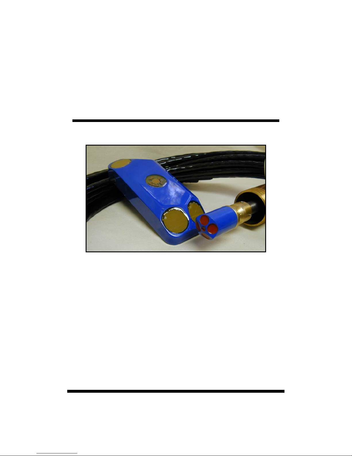
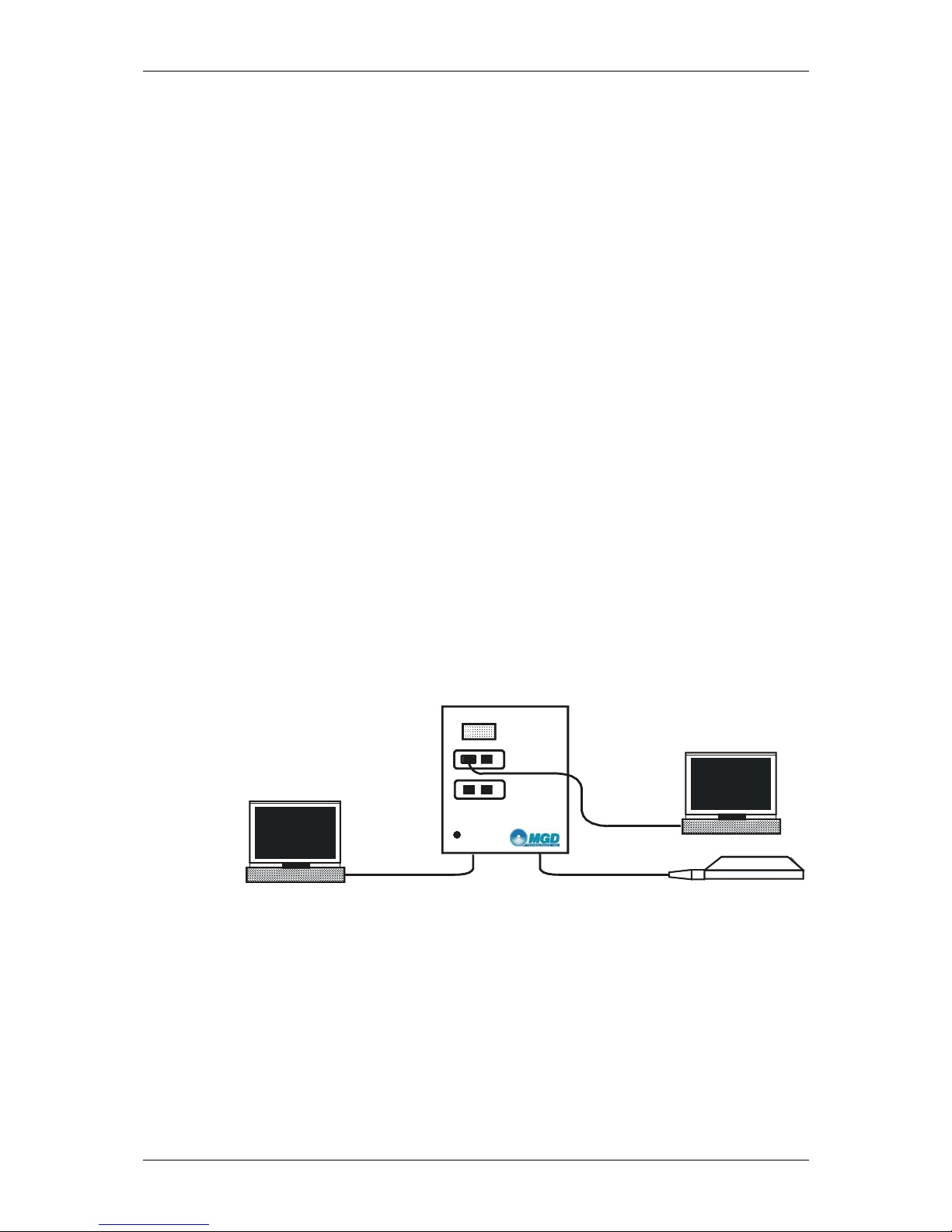
Figure 1-13 illustrates the three major components of a ADFM system. Two
components are installed at each site: a transducer, installed in the bottom
of a pipe or channel, and its Electronics Unit, installed nearby in a nonhazardous atmosphere. These two components communicate with the third
system component, a remote host IBM compatible PC computer, either via
a Modem, or a serial data interface (RS-232 or RS- 422) .
Computer with Modem
Telephone line
Figure 1-1. ADFM Components
Serial cable
Laptop computer
TransducerTransducer cable
ADFM Technical Manual (January 2000) page 1-3
Chapter 1
To allow measurements close to the bottom of the pipe or channel and to
minimize debris collection on the transducer, the ADFM transducer is designed to have a low profile. It therefor e contai ns a mini mum of re quired
electronics. The Electronics Unit and transducer contain all circuitry and
systems needed to measure directional flow, the level within the sewer pipe,
to record results, and to transfer data from and to local or remote locations.
Use of a laptop computer running Windows 95 and the WinADFM software
is recommended for initial setup of the ADFM on-site. Subsequent data
collection and re-programming may be performed locally or remotely via
modem if a telephone telemetry connection is available.
1-4.1 What is an ADFM?
The ADFM V elocity Profiler™ (ADFM) is a flow meter based on the Doppler principle. The ADFM consists of a transducer assembly mounted in the
flow, a signal processing unit and an interface cable
1-4.2 Principles of Operation
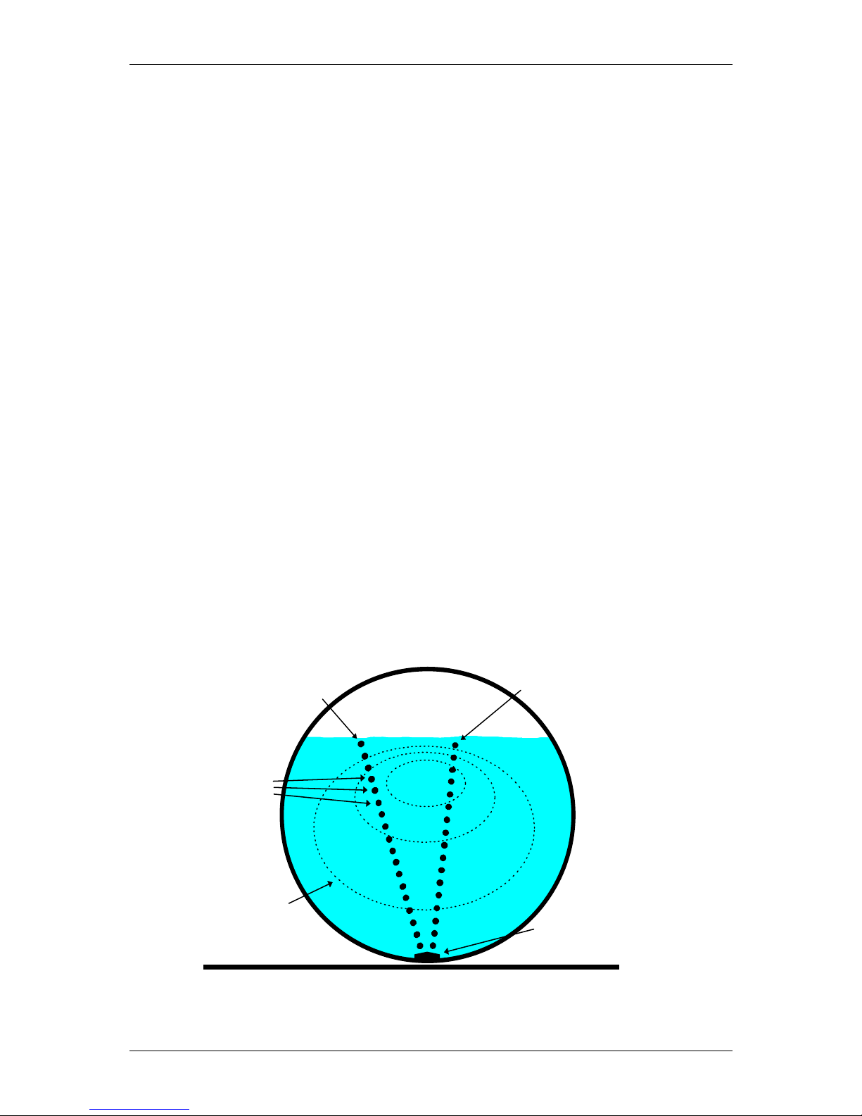
Figure 1-24 shows a typical ADFM installation for measuring open channel
flow in a pipe. A transducer assembly is mounted on the invert of a pipe or
channel. Piezoelectric ceramics emit short pulses along narrow acoustic
beams pointing in different directions. Echoes of these pulses are backscattered from material suspended in the flow. As this material has motion relative to the transducer, the echoes are Doppler shifted in frequency. Measurement of this frequency enables the calculation of the flow speed. A fifth
ceramic mounted in the center of the transducer assembly, and aimed vertically, is used to measure the depth.
Velo c ity Profile # 2
Dept h c e lls
Velo c ity P ro f ile # 1
Flow pattern
Figure 1-2. Typical ADFM installation
page 1-4 MGD Technologies, Inc.
transducer
Introduction to the ADFM Velocity Profiler™
The ADFM divides the return signal into discrete regular intervals that correspond to different depths in the flow. Velocity is calculated from the frequency shift measured in each interval. The result is a profile, or linear distribution of velocities, along the direction of the beam. Each of the small
black circles in Figure 1-24 represent an individual velocity measurement in
a small volume known as a depth cell.
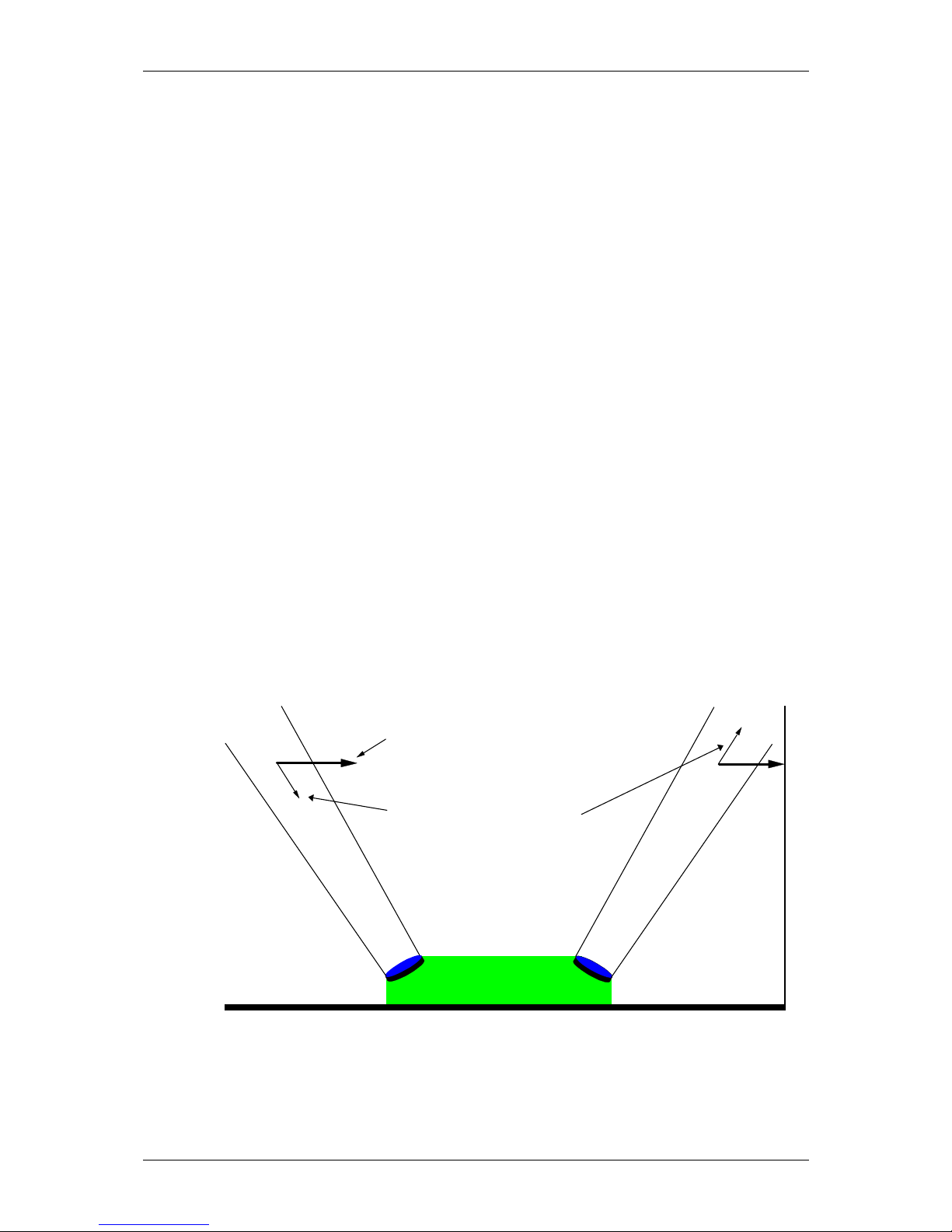
The directions of the velocity profiles in Figure 1-24 are based on the geometry of the ADFM’s transducer assembly. Figure 1-35 shows a side view
of the transducer assembly. The profiles shown in Figure 1-24 are generated from velocity data measured by an upstream and downstream beam
pair. The data from one beam pair are averaged to generate Profile #1, and
a beam pair on the opposite side of the transducer assembly generates Profile #2.
Since Doppler measurements are directional, only the component of velocity along the direction of transmit and receive is measured, as shown in
Figure 1-35. Narrow acoustic beams are required to accurately determine
the horizontal velocity from the measured component. The narrow acoustic
beams of the ADFM insure that this measurement is accurate. Also, the
range-gate times are short and the depth cells occupy a small volume - cylinders approximately 5 centimeters (2 inches) long and 5 centimeters (2
inches) in diameter. This insures that the velocity measurements are truly
representative of that portion of the flow. Potential bias in the return energy
spectrum due to range dependent variables is avoided. The result is a very
precise measurement of the vertical and transverse distribution of flow velocities.
Flow Velocity Vector
Vector Componen t
Figure 1-3. ADFM Beam Geometry
The velocity data from the two profiles are entered into an algorithm to determine a mathematical description of the flow velocities throughout the
ADFM Technical Manual (January 2000) page 1-5

Chapter 1
entire cross-section of the flow. The algorithm fits the basis functions of a
parametric model to the actual data. The result predicts flow velocities at
all points throughout the flow. These results are integrated over the crosssectional area to determine the discharge.
The key benefit to this approach is that the system will operate accurately
under different hydraulic conditions. As hydraulic conditions change, the
change will manifest itself in the distribution of velocity throughout the
depth of flow. As the ADFM is meas ur ing the velocit y di stri buti on dir ectl y,
it will adapt to the changes in hydraulics, and generate a flow pattern that is
representative of the new hydraulic conditions, insuring an accurate estimate of flow rate.
1-4.3 User Data Interfaces
The ADFM has three user data interfaces, which are listed in Ta ble 1- 16 below.
Table 1-1: User Data Interface Types
Type: Description:
RS-232 Serial Data Interface, EIA standard RS-232C, used for local data
communication with the ADFM. Not to be used over distances more
than 15 meters. Maximum baud rate is 57600 Baud.
RS-422 Serial Data Interface, EIA standard RS-422, used for local or remote
data communication over distances up to 1.2 km. Maximum Baud rate
is 115 kBaud.
Modem 28800 bps Modem with data compression and error correction
capabilities, used for remote data communication with the ADFM.
For a complete set of specifications for the serial data interfaces please refer
to the EIA specifications. For more information on available modems,
please contact MGD Te chnologies Inc.
page 1-6 MGD Technologies, Inc.

Equipment Setup and Installation
Chapter
Equipment Setup and Inst allation
2-1 Introduction
This section of the manual contains information and instructions for inspection, configuration, testing, installation, and deployment of the ADFM Velocity Profiler™. Included in this section are:
• Initial inspection procedures
• Connecting the ADFM components
• Power supply options
• Built-in tests (BITs)
• Final preparations for use
• Installing and deployment
• Packing and shipping information
The general sequence of events in installing and deployment of an ADFM
are:
• Prepare portable computer to be taken to installation site.
• Perform pre-installation equipment and operational checks.
• Connect the ADFM Transducer and Electronics Unit via the
Transducer Cable.
• Measure channel dimensions and determine geometry.
• Setup ADFM configuration file for each installation site.
• Install the ADFM transducer and electronics unit, conduct final
testing.
• Program desired data logging parameters into the ADFM.
• Connect phone line to ADFM Modem port, if required.
ADFM Technical Manual (January 2000) page 2-1
Chapter 2
s
2-2 Initial Inspection
On receipt, inspect the shipping contai ner for damage. If shipping container
or cushioning material is damaged, it should be kept until the contents of
the shipment have been c h ecke d for c ompleteness and the system has been
checked both mechanically and electrically. If the contents are incomplete,
if there is evidence of mechanical damage or defects, or if the syste m indicates a failure in some component during the initial testing procedure,
please notify MGD Technologies Inc. as soon as possible. If the shipping
container is damaged, or the cushioning material shows signs of stress, notify the carrier as well as MGD Technologies Inc. Keep the shipping materials for the carrier’s inspection.
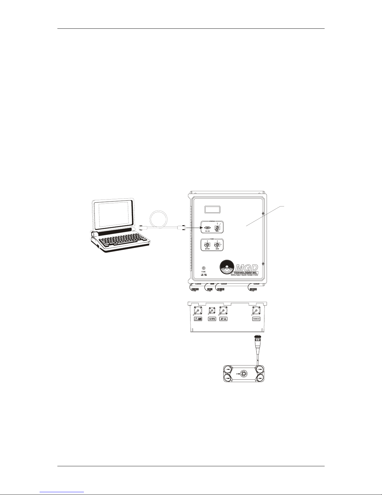
2-3 System Interconnection
Use Figure 2-12 to connect the ADFM cables and the computer.
Internal Batterie
Serial Cable
(Optional - for
Testing Only)
Laptop Computer
(Optional - for Testing Only)
115 to 230 VAC 50 - 60 Hz
(Optional)
Figure 2-1. ADFM System Interconnection
Modem Port (Optional)
24 to 36 VDC (Optional)
Transducer
Cable
page 2-2 MGD Technologies, Inc.
Equipment Setup and Installation
2-3.1 Connecting the Transducer Cable to the Electronics Unit
The transducer cable is a multi-pair, multi-shielded cable designed specifically for use with the ADFM. The standard cable length is 15 meters (49
feet), but other cable lengths are available. Contact MGD Technologies Inc.
for details. Extension cables are not recommended due to EMI/RFI constraints.
CAUTION. Use caution when mating or unmating the transducer cable to
the transducer assembly and Electronics Unit to avoid damage to the
connector hardware. UNDER ALL CIRCUMSTANCES, THE INTRUSION
OF WATER OR ANY OTHER FOREIGN MATTER INTO THE
CONNECTOR CONTACT AREA MUST BE AVOIDED, SINCE THIS MAY
RESULT IN PERMANENT DAMAGE TO THE CONNECTOR AND MAY
RENDER THE ADFM INOPERABLE.
The transducer cable connects to the electronics unit using a 14-position
keyed connector. The receptacle on the electronics unit is located on the
bottom right side of the unit.
To make the connection, remove the blank cap from the receptacle on the
electronics unit. Insert the cable connector into the receptacle, rotating it
until the keyed portions are properly aligned. Thread the coupling ring onto
the receptacle to complete the connection. Reverse this procedure when
disconnecting the cable from the electronics unit.
2-3.2 Power Supply to the ADFM
CAUTION. BEFORE connecting mains (AC) power to this instrument, be
sure the line voltage selector jumpers inside the Electronics Unit is set
properly and the correct fuse is installed.
Power Supply Options
The ADFM is designed to operate from one of three independent power
sources: internal batteries, external DC power supply, or external AC power
supply. All sources may be used concurrently; the source that supplies the
highest voltage will automatically supply power to the system. Mains (AC)
power is converted to a DC supply of approximately 28-30 VDC after rectification and filtering inside the ADFM. By combining external mains
power with internal batteries, one can obtain uninterrupted operation of the
ADFM during brief power outages. Both front panel power switches must
be in the “On” position for this to occur.
Two internal battery options are available for the ADFM. The standard configuration consists of four 6-volt alkaline lantern batteries wit h spri ng t erminals. Recommended alkaline batteries are the Eveready Energizer, Model
EN529. These alkaline batteries have approximately 2.5 times the
ADFM Technical Manual (January 2000) page 2-3
Chapter 2
power/life of the lead-acid type. An optional conversion kit for using two
(2) 12-volt, 7-amp hour sealed lead-acid gel cell batteries is also available.
The ADFM will operate from an external DC power supply of 12 to 35
volts, with a power consumption of 3 watts maximum. A supply voltage of
24 to 35 VDC is recommended to allow operation from the internal batteries when the external power supply is interrupted. Operation from external
mains (AC) power requires a power s o urce of 115 or 230 VAC, ±10%; 50 to
60 Hz, with a power consumption of 5 VA maximum.
Line Voltage Selection
The ADFM should be delivered pre-configured for the proper voltage. The
current configuration will be indicated by a sticker on the exterior of the
Electronics Unit adjacent to the AC input connector. Before applying mains
power, verify that the ADFM is configured for the correct line voltage. If
the ADFM is configured for the wrong voltage, please contact MGD Technologies Inc. for instructions.
Mains (AC) Power Cable
CAUTION. BEFORE CONNECTING THIS INSTRUMENT TO MAINS, the
protective earth (ground) terminal of the instrument must be connected to
the protective conductor of the mains power cord. The mains power cable
must be connected to a protective earth contact. The protective action
must not be negated by use of an extension cord (power cable) without a
protective conductor (grounding). Grounding a two-conductor outlet does
not provide an instrument ground.
This instrument is provided with a three-conductor power cable for mains
supply. When connected to an appropriate power outlet, this cabl e grounds
the instrument unit. The mains power supply cable normally ships as a pigtail assembly for field wiring to the mains power supply. The connector on
the cable mates with the left-most receptacle on the ADFM, and that is the
only receptacle it will mate with. Wiring assignments for the mains powe r
cable are as follows:
Pin Color Function
(L) 1 Brown Line
(N) 2 Blue Neutral
(PE) 3 Green Protective Earth
DC Power Supply Cable
This instrument is provided with a two-conductor cable for DC power supply. This cable provides no grounding. The DC power supply cable normally ships as a pigtail assembly for field wiring to the DC power supply.
page 2-4 MGD Technologies, Inc.

Equipment Setup and Installation
The power supply cable mates with the smallest connector on the ADFM.
Wiring assignments for the power cable are as follows:
Pin Color Function
(+) 1 Red + DC
(-) 4 Black - DC
2-3.3 Applying Power
Two key switches on the inner front panel control power to the ADFM. A
third momentary key switch provides a reset function. Ensure that both
power switches are in the “off” position, and the reset switch is not held in
the “reset” position. Connect the appropriate power supply cables to the
ADFM and the power source, if required. Ensure that the batteries are securely mounted in the ADFM and that the battery supply wiring harness is
attached. Use the supplied switch-key to switch the appropriate power
source switch(es) to the On-position, indi cated by “1”; this will power-up
the ADFM. If you intend to use both mains and battery power, ensure that
both switches are on.
2-4 Built In Tests (BITs)
When power is first applied to the ADFM, an internal self-test will automatically be performed. Result messages will scroll on the LCD display,
culminating in a display showing the ADFM firmware version number on
the first line and a hexadecimal-coded error map on the second line. The
software used to operate the ADFM will periodically report and reset the
error code map, and to re-run selected tests. By interpretation and further
fault isolation, it is possible to isolate a hardware problem to a least replaceable assembly (LRA) level. For a list of LRAs refer to Chapter 4-
Table 4-1, page 4-6: List of Least Re plac eable Assemblies
2-4.1 Testing Interval
Routine execution of the built-in tests is not required during normal system
operation. Execution of selected built-in tests from software is recommended quarterly or at each battery change, whichever is more frequent.
The built-in tests should also be performed whenever a hardware problem
with the ADFM is suspected. See
further details.
2-4.2 Test Record
The WinADFM software by default will create a log containing details of
all ADFM operations, including the status of the error code map and the results of all built-in tests. No further test record is required unless specifically requested by Technical Support Personnel.
.
Chapter 3 and the software manual for
ADFM Technical Manual (January 2000) page 2-5

Chapter 2
2-4.3 Power-UP BIT Procedure/Sequence
a. Switch power to the ADFM off.
b. Switch power on again; however, make sure at least ten minutes
have passed since all power was switched off. The ADFM’s LCD
display should show firmware version and error code map followed
by the “wake up message”:
RD Instruments:
------------------Acoustic Doppler
Flow Meter
c. The ADFM’s LCD display should begin displaying the results of the
power-up BIT, as these tests are executed. The power-up BIT tests
will take approximately one or t wo mi nutes t o per for m af ter which
the LCD display will show the firmware version and BIT error code
map (see Chapter 5 for details):
ADFM Ver. V6.xx
09000080
d. To repeat the power-up BIT tests you may turn and release the Reset
key switch, located on the front panel of the Electronics Unit.
2-5 Final Preparations for Use
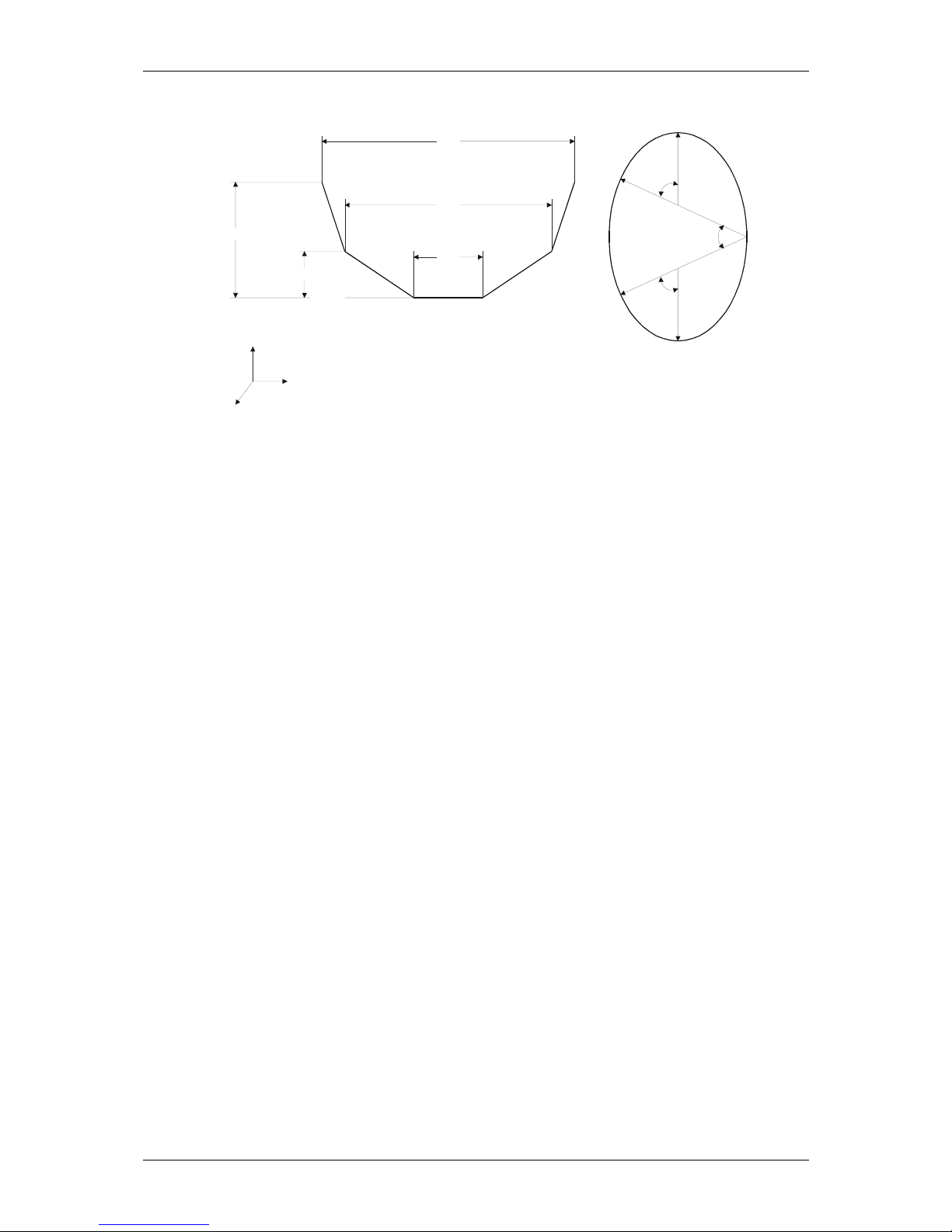
2-5.1 Measure Pipe or Channel Geometry
In order for the ADFM to measure flow accurately, it must have information
about the pipe or channel in which it is installed. Refer to Figure 2-27 for a
diagram of the channel geometries directly supported by the ADFM. The
pipe/channel shape must be symmetrical about the vertical cente rli ne. Application of the ADFM in pipes or channels of other geometries may be
possible. Please contact MGD Technologies Inc. with specific detai ls of
your application for further information.
page 2-6 MGD Technologies, Inc.
Equipment Setup and Installation
:
W3
W2
H3
W1
H2
H1
z
Rectangular and Trapezoidal shaped:
y
x
H = Heights in meters
W = Widths in meters
R2
R2
Circular or Egged-shaped
a = Angles in degrees
R3
a3
a2
a1
R1
R = Radii in meters
Figure 2-2. Pipe Geometry and Parameters
During installation, the following parameters need to be recorded, as they
are needed by the software to estimate discharge:
• Cross-sectional geometry: For rectangular channels, the width
(W) and the height (H) need to be recorded. For circular
pipes/channels the, radii (R) and angles (a) nee d to be recorde d.
These parameters will be entered into software and used to estimate discharge. Note that for a circular channel only the Diameter (D) needs to be recorded.
• Normal distance from the surface of the transducer fifth beam t o
the invert of the pipe: Enter these dimensions into the “Zero Offset” box in the WinADFM setup screen.
• Level of silt in the pipe or channel should be entered into the
“Bed Level” box in the WinADFM setup screen.
2-5.2 Prepare Installation Hardware
Installation hardware is available from MGD Technologies Inc. for a variety
of channel shapes and sizes. Please contact MGD Technologies Inc. for further information, or if you desire assistance in applying the ADFM to your
specific situation.
The ADFM transducer assembly includes three drilled and tapped mounting
holes. To avoid damage to the transducer assembly and ceramics, these
holes are the only locations that should be used to mount the transducer assembly to the installation hardware. These mounting holes are drilled and
tapped for a metric size machine screw, size M6-1.0. Inserts are available
to convert the existing holes from metric M6 to metric M3 and US standard
#6-32 size threads.
ADFM Technical Manual (January 2000) page 2-7
Chapter 2
Installation of the ADFM transducer assembly must also comply with the
following parameters to maintain the accuracy of the final installation:
• Transducer must be installed in such a way that the vertical beam
(beam 5) is oriented normal with respect to the pipe’s or channel’s invert. Note that the vertical beam is normal to the transducer’s top surface.
• Transducer must not be rotated about the vertical Z-axis. A sight-
ing device or similar s h oul d be used t o mi ni mi ze r otat iona l mi s alignment.
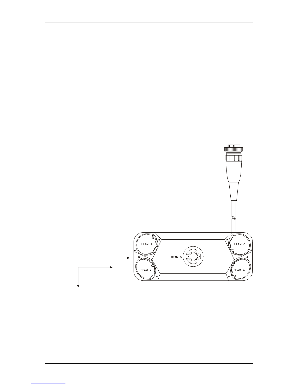
• Transducer must be installed such that positive longitudinal flow
direction is from the “non-cable” side of the transducer to the
“cable” side. See Figure 2-38 below for further explanation of
the flow direction.
TOP
Positive
(Downstream)
direction of flow
+v
+z out of page
+x
Figure 2-3. Transducer Orientation
2-5.3 Install Software and Configure Station File
Before the ADFM can be used in a specific application, it must be
programmed for that application. This is most easily done using the
WinADFM software. See Chapter 3 and the Software Manual for further
details.
page 2-8 MGD Technologies, Inc.

Equipment Setup and Installation
2-5.4 Installing and Deploying the ADFM
Detailed procedures for installing the ADFM in a specific application cannot be provided without detailed knowledge of the application. Please contact MGD Technologies Inc. if you desire information or assistance in your
application. “Deployment” refers to the programming of an ADFM with
the site, channel, profiling, and data logging characteristics desired at the
site. Deployment is discussed in more detail in Chapter 3 and the software
manual.
2-6 Packaging and Shipping the ADFM
Clean the Electronics Unit and transducer assembly with mild soap and water prior to packaging and shipment.
vents as they will damage these surfaces. MILD chlorine bleach solutions
may be used if odors persist or if disinfection of the unit is desired. Use
caution to prevent water from entering the Electronics Unit housing while
cleaning. Ensure that the unit is completely dry prior to packaging and
shipment to avoid corrosion or other damage during shipment. The ADFM
may be shipped with batteries installed, however, all key switches should be
in the “off” position for shipment. Removal of batteries from the unit may
be desirable to reduce the shipping we ight.
DO NOT use abrasive agents or sol-
2-6.1 Tagging For Service
If the instrument is to be shipped to MGD Technologies Inc. for service or
repair, attach a tag to the instrument identifying the owner, address of
owner, complete instrument model and serial number, and a description of
the service required. Mark the container FRAGILE to ensure careful handling. In any correspondence, refer to the system by model and full serial
number.
2-6.2 Packaging
The original factory packaging material should be stored for reuse in the
event it becomes necessary to transport the ADFM. If the original packaging material is unavailable or unserviceable, mater ials identi ca l or eq uivalent to those used in factory packaging are available through MGD Technologies Inc.
For repackaging with commercially available materials follow these instructions:
• Wrap Electronics Unit and transducer assembly separately in
bubble wrap or other cushioning material.
• Use strong shipping container suitable for the weight of the
ADFM. Shipping containers made of wood or plastic are prefer-
ADFM Technical Manual (January 2000) page 2-9

Chapter 2
able, but corrugated shipping boxes of at least 200-lb. test may
be used.
• Use a layer of shock-absorbing materiel, at least 25 mm (1 in)
thick around all sides of the Electronics Unit and transducer assembly to firmly cushion and prevent movement inside the container. Special care must be taken to protect the transducer ceramics on the upper face of the transducer assembly from damage.
• Seal shipping container securely.
• Mark shipping container FRAGILE to ensure careful handling.
• In any correspondence, refer to system by model number and se-
rial number.
page 2-10 MGD Technologies, Inc.
 Loading...