

Teledyne ACCQPrep HP125 Installation And Operation Manual
CCQPrep HP125
60-5233-812
Copyright © 2017 Teledyne Technologies Incorporated. All rights reserved.
Rev. C, January 2019
A
Installation and Operation Guide

ACCQPrep HP125 Installation and Operation Guide
WARNINGWARNING
WARNINGWARNING
WARNINGWARNING
CAUTION
WARNINGWARNING
Safety Warnings
ACCQPrep HP125 Installation and Operation Guide
Safety Warnings
Safety Before installing, operating, or maintaining this equipment, it is
imperative that all hazards and preventive measures are fully
understood. While specific hazards may vary according to
location and application, take heed in the following general
warnings:
Liquids associated with this instrument may be classified
as carcinogenic, biohazard, flammable, or radioactive.
Should these liquids be used, it is highly recommended that
this application be accomplished in an isolated
environment designed for these types of materials in
accordance with federal, state, and local regulatory laws,
and in compliance with your company’s chemical/hygiene
plan in the event of a spill.
Avoid hazardous practices! If you use this instrument in
any way not specified in this manual, the protection
provided by the instrument may be impaired.
If you are using flammable solvents or chemicals with this
system, vapor concentration levels may exceed the
maximum exposure levels as recommended by OSHA
Guide 1910.1000. To reduce those levels to a safe exposure,
Teledyne Isco recommends that you place the system in a
laboratory hood designed for the purpose of ventilation.
This hood should be constructed and operated in
accordance with federal state and local regulations. In the
event of a solvent or chemical spill, your organization
should have a plan to deal with these mishaps. In all cases,
use good laboratory practices and standard safety
procedures.
Hazard Severity Levels This manual applies Hazard Severity Levels to the safety alerts.
These three levels are described in the sample alerts below.
Cautions identify a potential hazard, which if not avoided, may
result in minor or moderate injury. This category can also warn
you of unsafe practices, or conditions that may cause property
damage.
Warnings identify a potentially hazardous condition, which
if not avoided, could result in death or serious injury.
3
ACCQPrep HP125 Installation and Operation Guide
DANGER
Safety Warnings
DANGER – limited to the most extreme situations
to identify an imminent hazard, which if not
avoided, will result in death or serious injury.
Hazard Symbols The equipment and this manual use symbols used to warn of
hazards. The symbols are explained in the table below.
The exclamation point within the triangle is a
warning sign alerting you of important instructions
in the instrument’s technical reference manual.
The lightning flash and arrowhead within the triangle is a warning sign alerting you of “dangerous
voltage” inside the product.
Hazard Symbols
Warnings and Cautions
Symboles de sécurité
Ce symbole signale l’existence d’instructions
importantes relatives au produit dans ce manuel.
Ce symbole signale la présence d’un danger
d’électocution.
Warnungen und Vorsichtshinweise
Das Ausrufezeichen in Dreieck ist ein Warnzeichen, das Sie darauf aufmerksam macht, daß
wichtige Anleitungen zu diesem Handbuch
gehören.
Der gepfeilte Blitz im Dreieck ist ein Warnzeichen,
das Sei vor “gefährlichen Spannungen” im
Inneren des Produkts warnt.
Advertencias y Precauciones
Esta señal le advierte sobre la importancia de las
instrucciones del manual que acompañan a este
producto.
Esta señal alerta sobre la presencia de alto
voltaje en el interior del producto.
4

ACCQPrep HP125 Installation and Operation Guide
Safety Warnings
For Additional
Information
Technical assistance for the Teledyne Isco ACCQPrep HP125 can
be obtained from:
Teledyne Isco
4700 Superior St.
Lincoln NE 68504
Phone: (800) 775-2965 or (402) 464-0231
Fax: (402) 465-3001
E-mail: IscoService@teledyne.com
5

ACCQPrep HP125 Installation and Operation Guide
Safety Warnings
6

ACCQPrep HP125
Table of Contents
Section 1 Introduction
1.1 Overview . . . . . . . . . . . . . . . . . . . . . . . . . . . . . . . . . . . . . . . . . . . . . . . . . . . . . . . . . . 1-1
1.2 Product Overview . . . . . . . . . . . . . . . . . . . . . . . . . . . . . . . . . . . . . . . . . . . . . . . . . . . 1-1
1.3 Operating Overview . . . . . . . . . . . . . . . . . . . . . . . . . . . . . . . . . . . . . . . . . . . . . . . . . 1-3
1.3.1 Multiple Control Possibilities . . . . . . . . . . . . . . . . . . . . . . . . . . . . . . . . . . . . 1-3
1.3.2 File Storage . . . . . . . . . . . . . . . . . . . . . . . . . . . . . . . . . . . . . . . . . . . . . . . . . . 1-3
1.4 Safety Components . . . . . . . . . . . . . . . . . . . . . . . . . . . . . . . . . . . . . . . . . . . . . . . . . . 1-3
1.5 Specification . . . . . . . . . . . . . . . . . . . . . . . . . . . . . . . . . . . . . . . . . . . . . . . . . . . . . . . 1-4
Section 2 Installation
2.1 ACCQPrep Installation. . . . . . . . . . . . . . . . . . . . . . . . . . . . . . . . . . . . . . . . . . . . . . . 2-1
2.2 Setting Up the System . . . . . . . . . . . . . . . . . . . . . . . . . . . . . . . . . . . . . . . . . . . . . . . 2-1
2.2.1 Pump Installation . . . . . . . . . . . . . . . . . . . . . . . . . . . . . . . . . . . . . . . . . . . . . 2-2
2.2.2 Solvent Line Installation . . . . . . . . . . . . . . . . . . . . . . . . . . . . . . . . . . . . . . . . 2-4
2.2.3 Fluid Line Installation . . . . . . . . . . . . . . . . . . . . . . . . . . . . . . . . . . . . . . . . . 2-5
2.2.4 ACCQPrep Equipped with Optional ELSD . . . . . . . . . . . . . . . . . . . . . . . . . 2-6
2.2.5 Priming Steps . . . . . . . . . . . . . . . . . . . . . . . . . . . . . . . . . . . . . . . . . . . . . . . . . 2-8
2.3 Installing the Manual Injection Port . . . . . . . . . . . . . . . . . . . . . . . . . . . . . . . . . . . . 2-9
2.4 Installing the AutoSampler . . . . . . . . . . . . . . . . . . . . . . . . . . . . . . . . . . . . . . . . . . 2-10
2.4.1 Establishing the Fluid Connections . . . . . . . . . . . . . . . . . . . . . . . . . . . . . . 2-16
2.5 Column Installation . . . . . . . . . . . . . . . . . . . . . . . . . . . . . . . . . . . . . . . . . . . . . . . . 2-19
2.5.1 Column mounting . . . . . . . . . . . . . . . . . . . . . . . . . . . . . . . . . . . . . . . . . . . . 2-19
2.5.2 Column Configuration . . . . . . . . . . . . . . . . . . . . . . . . . . . . . . . . . . . . . . . . . 2-21
2.5.3 Column Select Valve
(Optional) . . . . . . . . . . . . . . . . . . . . . . . . . . . . . . . . . . . . . . . . . . . . . . . . . . . 2-21
2.6 Installation Troubleshooting . . . . . . . . . . . . . . . . . . . . . . . . . . . . . . . . . . . . . . . . . 2-22
Section 3 Configuration
3.1 Configuration of the ACCQPrep. . . . . . . . . . . . . . . . . . . . . . . . . . . . . . . . . . . . . . . . 3-1
3.2 Network Configuration . . . . . . . . . . . . . . . . . . . . . . . . . . . . . . . . . . . . . . . . . . . . . . . 3-2
3.3 User Preferences . . . . . . . . . . . . . . . . . . . . . . . . . . . . . . . . . . . . . . . . . . . . . . . . . . . . 3-2
3.4 Prep HPLC. . . . . . . . . . . . . . . . . . . . . . . . . . . . . . . . . . . . . . . . . . . . . . . . . . . . . . . . . 3-3
3.4.1 Define a Column . . . . . . . . . . . . . . . . . . . . . . . . . . . . . . . . . . . . . . . . . . . . . . 3-4
3.4.2 Delete a Column . . . . . . . . . . . . . . . . . . . . . . . . . . . . . . . . . . . . . . . . . . . . . . 3-4
3.4.3 Creating Other Methods . . . . . . . . . . . . . . . . . . . . . . . . . . . . . . . . . . . . . . . . 3-5
3.4.4 Creating Focused Gradients . . . . . . . . . . . . . . . . . . . . . . . . . . . . . . . . . . . . . 3-6
Section 4 Operation
4.1 Introduction. . . . . . . . . . . . . . . . . . . . . . . . . . . . . . . . . . . . . . . . . . . . . . . . . . . . . . . . 4-1
4.2 Method Selection. . . . . . . . . . . . . . . . . . . . . . . . . . . . . . . . . . . . . . . . . . . . . . . . . . . . 4-1
4.3 Starting a Separation . . . . . . . . . . . . . . . . . . . . . . . . . . . . . . . . . . . . . . . . . . . . . . . . 4-2
4.3.1 Separation with an AutoInjector . . . . . . . . . . . . . . . . . . . . . . . . . . . . . . . . . 4-2
4.3.2 AutoInjection Operating Steps . . . . . . . . . . . . . . . . . . . . . . . . . . . . . . . . . . . 4-5
4.3.3 Separation using an AutoSampler Module . . . . . . . . . . . . . . . . . . . . . . . . . 4-7
4.3.4 Using the Queue Tab . . . . . . . . . . . . . . . . . . . . . . . . . . . . . . . . . . . . . . . . . . . 4-7
1

ACCQPrep HP125
Table of Contents
4.3.5 AutoSampler Injection Techniques . . . . . . . . . . . . . . . . . . . . . . . . . . . . . . . . 4-9
4.3.6 Fraction Collection with the AutoSampler . . . . . . . . . . . . . . . . . . . . . . . . . 4-12
4.4 Operation Troubleshooting. . . . . . . . . . . . . . . . . . . . . . . . . . . . . . . . . . . . . . . . . . . 4-13
Section 5 PeakTrak
5.1 Overview . . . . . . . . . . . . . . . . . . . . . . . . . . . . . . . . . . . . . . . . . . . . . . . . . . . . . . . . . . 5-1
5.1.1 PeakTrak Window Elements . . . . . . . . . . . . . . . . . . . . . . . . . . . . . . . . . . . . . 5-1
5.1.2 Method File . . . . . . . . . . . . . . . . . . . . . . . . . . . . . . . . . . . . . . . . . . . . . . . . . . 5-1
5.1.3 Run File . . . . . . . . . . . . . . . . . . . . . . . . . . . . . . . . . . . . . . . . . . . . . . . . . . . . . 5-2
5.2 PeakTrak Menu Options. . . . . . . . . . . . . . . . . . . . . . . . . . . . . . . . . . . . . . . . . . . . . . 5-2
5.2.1 File . . . . . . . . . . . . . . . . . . . . . . . . . . . . . . . . . . . . . . . . . . . . . . . . . . . . . . . . . 5-3
5.2.2 Method Editor . . . . . . . . . . . . . . . . . . . . . . . . . . . . . . . . . . . . . . . . . . . . . . . . 5-4
5.2.3 MS . . . . . . . . . . . . . . . . . . . . . . . . . . . . . . . . . . . . . . . . . . . . . . . . . . . . . . . . . . 5-5
5.2.4 Tools . . . . . . . . . . . . . . . . . . . . . . . . . . . . . . . . . . . . . . . . . . . . . . . . . . . . . . . . 5-6
5.2.5 Help . . . . . . . . . . . . . . . . . . . . . . . . . . . . . . . . . . . . . . . . . . . . . . . . . . . . . . . . 5-7
5.2.6 PeakTrak Windows . . . . . . . . . . . . . . . . . . . . . . . . . . . . . . . . . . . . . . . . . . . . 5-8
5.2.7 Method Editor . . . . . . . . . . . . . . . . . . . . . . . . . . . . . . . . . . . . . . . . . . . . . . . 5-12
5.2.8 Column Data . . . . . . . . . . . . . . . . . . . . . . . . . . . . . . . . . . . . . . . . . . . . . . . . 5-18
5.2.9 Files . . . . . . . . . . . . . . . . . . . . . . . . . . . . . . . . . . . . . . . . . . . . . . . . . . . . . . . 5-18
5.2.10 Set Data Path . . . . . . . . . . . . . . . . . . . . . . . . . . . . . . . . . . . . . . . . . . . . . . . 5-19
5.2.11 MS Method Development . . . . . . . . . . . . . . . . . . . . . . . . . . . . . . . . . . . . . 5-20
5.2.12 MS Manual Control . . . . . . . . . . . . . . . . . . . . . . . . . . . . . . . . . . . . . . . . . . 5-21
5.2.13 Ionization Settings . . . . . . . . . . . . . . . . . . . . . . . . . . . . . . . . . . . . . . . . . . . 5-22
5.2.14 Manual Control . . . . . . . . . . . . . . . . . . . . . . . . . . . . . . . . . . . . . . . . . . . . . 5-24
5.2.15 Configuration . . . . . . . . . . . . . . . . . . . . . . . . . . . . . . . . . . . . . . . . . . . . . . 5-24
5.2.16 Set Administrator Password . . . . . . . . . . . . . . . . . . . . . . . . . . . . . . . . . . . 5-25
5.3 Examples of PeakTrak actions . . . . . . . . . . . . . . . . . . . . . . . . . . . . . . . . . . . . . . . . 5-26
5.3.1 Editing a method . . . . . . . . . . . . . . . . . . . . . . . . . . . . . . . . . . . . . . . . . . . . . 5-26
5.3.2 Alternative Ways to Create Method Files . . . . . . . . . . . . . . . . . . . . . . . . . 5-30
5.3.3 Defining a Gradient . . . . . . . . . . . . . . . . . . . . . . . . . . . . . . . . . . . . . . . . . . . 5-30
5.3.4 Real-time Gradient Editing . . . . . . . . . . . . . . . . . . . . . . . . . . . . . . . . . . . . . 5-31
5.3.5 Bypassing the Injection Loop . . . . . . . . . . . . . . . . . . . . . . . . . . . . . . . . . . . 5-31
5.3.6 Monitoring the Purity Measure . . . . . . . . . . . . . . . . . . . . . . . . . . . . . . . . . 5-32
5.3.7 Viewing runs . . . . . . . . . . . . . . . . . . . . . . . . . . . . . . . . . . . . . . . . . . . . . . . . 5-32
5.3.8 Manual Control of the ACCQPrep . . . . . . . . . . . . . . . . . . . . . . . . . . . . . . . 5-35
Section 6 Maintenance
6.1 Introduction. . . . . . . . . . . . . . . . . . . . . . . . . . . . . . . . . . . . . . . . . . . . . . . . . . . . . . . . 6-1
6.1.1 Cleaning . . . . . . . . . . . . . . . . . . . . . . . . . . . . . . . . . . . . . . . . . . . . . . . . . . . . . 6-1
6.1.2 Collection Rack and Tray Cleaning . . . . . . . . . . . . . . . . . . . . . . . . . . . . . . . 6-1
6.2 System Standby and Shut Down . . . . . . . . . . . . . . . . . . . . . . . . . . . . . . . . . . . . . . . 6-1
6.2.1 Tubing Inspection . . . . . . . . . . . . . . . . . . . . . . . . . . . . . . . . . . . . . . . . . . . . . 6-2
6.3 Preventive Maintenance. . . . . . . . . . . . . . . . . . . . . . . . . . . . . . . . . . . . . . . . . . . . . . 6-3
6.4 Flow Cell Cleaning . . . . . . . . . . . . . . . . . . . . . . . . . . . . . . . . . . . . . . . . . . . . . . . . . . 6-4
6.4.1 Post Separation . . . . . . . . . . . . . . . . . . . . . . . . . . . . . . . . . . . . . . . . . . . . . . . 6-4
6.4.2 Quick Cleaning when Recommended . . . . . . . . . . . . . . . . . . . . . . . . . . . . . . 6-5
6.4.3 Monthly Flow Cell Cleaning . . . . . . . . . . . . . . . . . . . . . . . . . . . . . . . . . . . . . 6-6
6.5 ACCQPrep HP125 Maintenance . . . . . . . . . . . . . . . . . . . . . . . . . . . . . . . . . . . . . . . 6-7
6.5.1 Injection Valve Rotor Replacement . . . . . . . . . . . . . . . . . . . . . . . . . . . . . . . 6-7
6.5.2 Pump Seal Replacement . . . . . . . . . . . . . . . . . . . . . . . . . . . . . . . . . . . . . . . . 6-9
6.5.3 Seal Conditioning . . . . . . . . . . . . . . . . . . . . . . . . . . . . . . . . . . . . . . . . . . . . . 6-14
6.5.4 Check Valve Replacement . . . . . . . . . . . . . . . . . . . . . . . . . . . . . . . . . . . . . . 6-14
6.6 AutoSampler Maintenance. . . . . . . . . . . . . . . . . . . . . . . . . . . . . . . . . . . . . . . . . . . 6-18
6.7 ELSD Maintenance. . . . . . . . . . . . . . . . . . . . . . . . . . . . . . . . . . . . . . . . . . . . . . . . . 6-19
6.7.1 Cleaning the ELSD Detector . . . . . . . . . . . . . . . . . . . . . . . . . . . . . . . . . . . . 6-19
6.8 PurIon Maintenance . . . . . . . . . . . . . . . . . . . . . . . . . . . . . . . . . . . . . . . . . . . . . . . . 6-22
2

ACCQPrep HP125
Table of Contents
6.8.1 ESI and APCI Removal from PurIon S and PurIon L . . . . . . . . . . . . . . . . 6-22
6.8.2 ESI and APCI Replacement PurIon S and PurIon L . . . . . . . . . . . . . . . . . 6-22
6.8.3 Cleaning the Ionization Source Capillary . . . . . . . . . . . . . . . . . . . . . . . . . 6-22
6.8.4 Replacement of Ion Source Housing . . . . . . . . . . . . . . . . . . . . . . . . . . . . . . 6-23
6.8.5 Overpressure Error . . . . . . . . . . . . . . . . . . . . . . . . . . . . . . . . . . . . . . . . . . . 6-23
6.8.6 Check Valve Cleaning . . . . . . . . . . . . . . . . . . . . . . . . . . . . . . . . . . . . . . . . . 6-23
6.8.7 Replacing Check Valves . . . . . . . . . . . . . . . . . . . . . . . . . . . . . . . . . . . . . . . 6-24
6.8.8 PurIon Cone Cleaning . . . . . . . . . . . . . . . . . . . . . . . . . . . . . . . . . . . . . . . . . 6-24
6.8.9 Capillary Inlet Cone Removal . . . . . . . . . . . . . . . . . . . . . . . . . . . . . . . . . . . 6-25
6.8.10 Capillary Inlet Cone Cleaning . . . . . . . . . . . . . . . . . . . . . . . . . . . . . . . . . 6-25
6.8.11 Capillary Inlet Cone Installation . . . . . . . . . . . . . . . . . . . . . . . . . . . . . . . 6-26
6.8.12 PurIon Troubleshooting . . . . . . . . . . . . . . . . . . . . . . . . . . . . . . . . . . . . . . . 6-26
Appendix A
A.1 Diagrams for the AutoSampler and ACCQPrep . . . . . . . . . . . . . . . . . . . . . . . . . . . A-1
3

ACCQPrep HP125
Table of Contents
4

ACCQPrep HP125
WARNING
Section 1 Introduction
1.1 Overview This Installation Guide provides:
• Safety information
• Unpacking instructions
• Installation instructions, including connections with
Windows and iOS operating systems
• Certification and warranty information
The Operating section will guide you on basic system operation.
1.2 Product Overview The Teledyne Isco ACCQPrep HP125 chromatography system
combines high resolution and productivity in a small footprint. It
features easy to use software, programmable gradients, UV
detection and peak collection, and automatic detection of collection tube racks. Its small size makes it a great personal
system and well-suited for operation within chemical hoods and
other limited indoor spaces. The extended pressure capability
supports operation of columns at high flow rates for maximum
throughput or added tolerance for high back pressures as
columns age.
Avoid hazardous practices! If you use this instrument in
any way not specified in this manual, the protection
provided by the instrument may be impaired; this may
increase your risk of injury.
The ACCQPrep HP125 is available in different configurations to
meet your needs. An optional Solvent Selector Valve Module supports up to three choices for solvent A and three different choices
for solvent B. Detection options include UV, UV/Vis, ELSD and a
mass spectrometer capable of detecting your compounds with up
to four individual mass signals including a range of masses.
Automation options include the AutoInjector for repeated injections of the same sample, an AutoSampler for single or repeated
injections of multiple samples, or a column select module supporting up to 4 Prep HPLC columns ranging from 4.6 mm up to
50 mm inner diameter (Larger columns may be used at less than
optimum flow rates).
1-1
ACCQPrep HP125
Section 1 Introduction
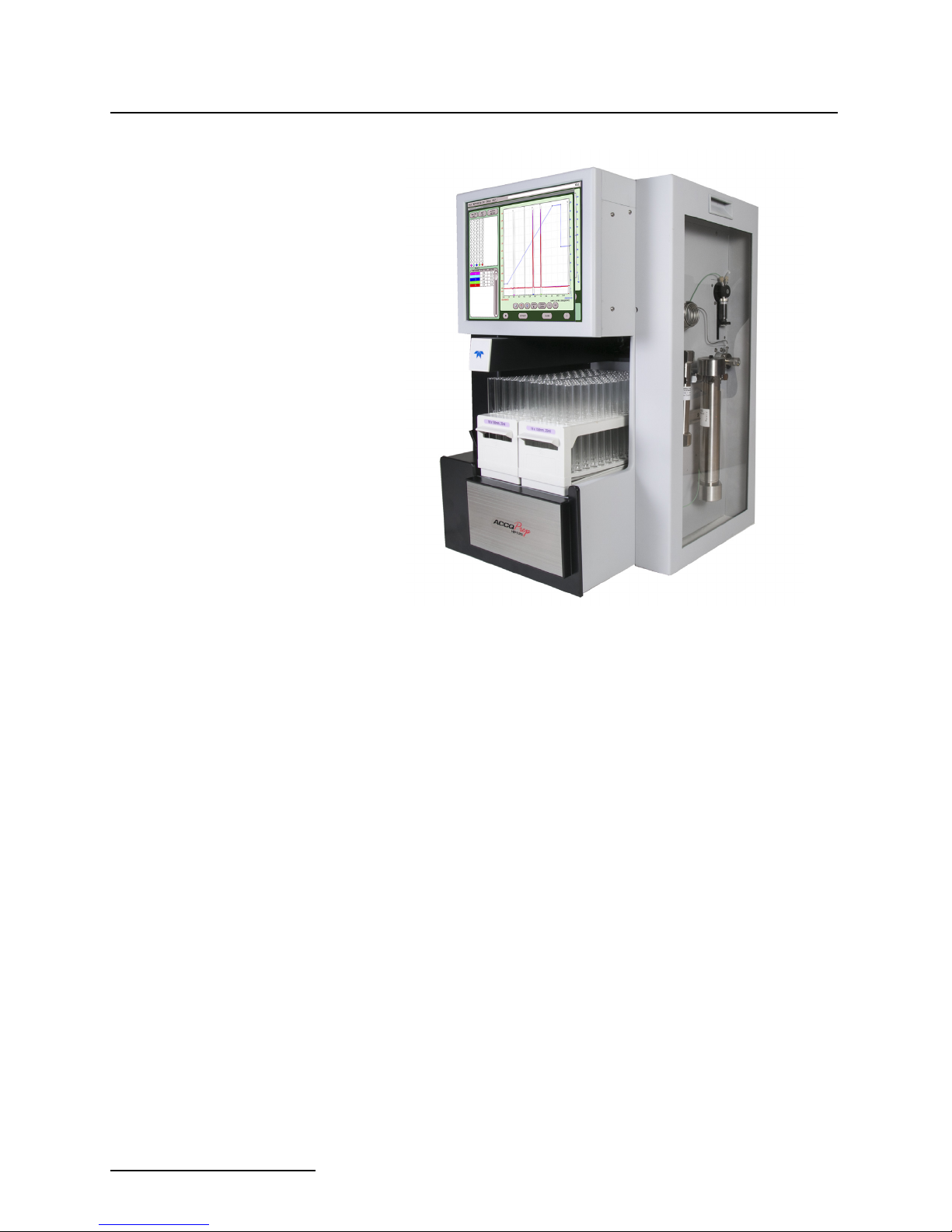
Figure 1-1 ACCQPrep HP125
ACCQPrep HP125 – This Prep HPLC system has flow rates
from 1-125 mL/min, with up to 6000 psi capability. A two component gradient can be formed from up to six solvents. The
system includes active solvent level sensing and detection of a
full waste container. The base system includes two fraction collection racks. With the optional AutoSampler up to four collection racks can be used. The RFID tagged racks can be replaced
while in operation with new racks for practically limitless
fraction collection.
ACCQPrep HP125 with optional ELSD – This system has
the same high performance features as the ACCQPrep HP125
system, but includes an internal evaporative light scattering
detector (ELSD). During operation, this detector can be combined with the UV (200–400 nm) or UV-vis (200–800 nm)
detection to isolate visible and UV absorbing compounds, as well
as compounds with little or no chromophores.
ACCQPrep HP125 with optional PurIon Mass
Spectrometer – This system has the same features as the
ACCQPrep HP125, but includes a mass spectrometer with a
detection range of 10 to 1200 Daltons (Da) (PurIon S) or 10-2000
Da (PurIon L systems). During purification, this system can be
combined with the UV (200 - 400 nm) or UV-V (200 - 800 nm)
detector to isolate visible and UV absorbing compounds, as well
as compounds with specific molecular weights or mass ranges.
1-2
ACCQPrep HP125
Note
Section 1 Introduction
1.3 Operating Overview The ACCQPrep HP125 system is equipped with a capacitive
touch screen display for local control.
The system also supports TCP/IP communication. This allows
direct control of the system by an external computer between
Ethernet ports of the ACCQPrep HP125 system and the computer.
TCP/IP communication also allows remote control of the system
via an established network. Remote controlling devices on the
network can be a Windows or Apple PC or Laptop, or an Apple
iSO mobile device (iPod Touch, iPhone, and iPad).
Teledyne Isco recommends that you obtain assistance from
your Information Technology department before attempting
direct or network connections. See Technical Note 28 Network-
ing Guidelines on the Isco website for more information.
1.3.1 Multiple Control
Possibilities
1.3.2 File Storage To support operation from a variety of direct and network con-
The system can be accessed from the built-in touch panel and up
to ten network devices. The touch panel shares control with all
connected devices. The system performs the most recent
command from any control input.
nections, the software and all files are stored in the ACCQPrep
HP125. This ensures that your compound purification methods
and run history files can be viewed from any connection.
Optionally, run files may be saved to a USB flash drive, a networked controlling computer, or a network drive.
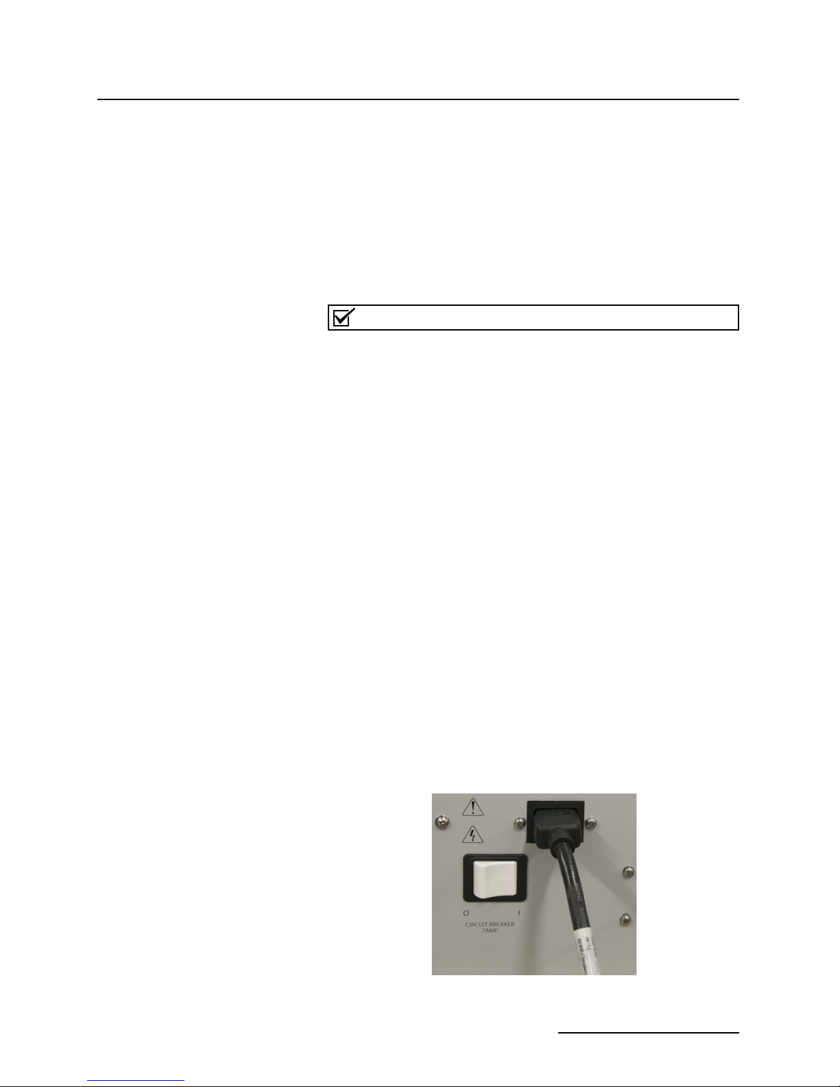
1.4 Safety Components The power cord is a safety disconnect for the ACCQPrep (Figure
1-2).
To remove power from the ACCQPrep remove the power cord by
pulling it straight out from the power inlet connector. The circuit
breaker is located adjacent to the power inlet connector. If an
internal circuit fault occurs, this breaker will trip. It can be reset
by pressing the end of the rocker labeled “1”. In addition,
switching the breaker manually to the “0” position will remove
power from the internal operating components.
Figure 1-2 Location of power cord for the ACCQPrep
1-3

ACCQPrep HP125
Section 1 Introduction
1.5 Specification
Table 1-1 ACCQPrep HP125
Dimensions of ACCQPrep
(Footprint without column or column cover
installed)
Dimensions of ACCQPrep AS 2x1 18.9 x 14.0 x 19.3 in (48.0 x 35.6 x 49.0 cm)
Weight
(Including AutoInjector, Column Selector
Valve Module, Solvent Selector Valve Module, and column cover)
Weight of ACCQPrep AS 2x1 27.3 lbs (12.4 kg)
User Interface 15" touchscreen
Power Input voltage range from 100 to 240 VAC,
Line Frequency 50/60 Hz
Ambient Temperature 20 to 40 °C (maximum temperature must be at least 15 °C below the
Humidity (when connected to power) 90% relative humidity maximum at 20 to 40 °C (non-condensing)
Flow Rate Range 1-125 mL/min, ELSD peak collection limited to 4-125 mL/min
Flow Rate Accuracy (tested with water at 6.9
bar or 100 psi)
Pressure Limit 414 bar (6000 psi) derated linearly from 6000 psi at 75 mL/min to
Pressure Accuracy 5% of full scale
27.5 x 14.0 x 20.0 in (69.9 x 35.6 x 50.8 cm)
93.2 lbs (42.3 kg)
106 lbs (48 kg) with optional Evaporative Light Scattering Detector
(ELSD)
300 VA maximum.
Line cord is the disconnect device. Power connection is via IEC
60320 C14 power inlet.
boiling point of the solvent)
± 2%
4000 psi at 125 mL/min
Gradient Formation Binary gradient 2 solvent inlets. Optional Solvent Selector Valve Mod-
Gradient Accuracy: ±1% of full scale
Peak Detection Modes Slope or threshold
Flow Cell Pathlength 0.3 mm, ±25% (Standard, other pathlengths available)
UV Detection Wavelength 200 to 400 nm, optional 200 to 800 nm UV-Vis
Wavelength Accuracy ±5 nm
Fraction Accuracy ±[2mL + (flow rate ÷ 60)]
ule expands to 3 solvents each for A & B
Optional ELSD
Gas Inlet Pressure 60 to 70 psig
Gas Consumption <2.5 SLPM
Spray Chamber Temperature Setting range: 10 to 60 °C
limited to minimum of 5 °C below ambient
Drift Tube Temperature Setting range: 30 to 90 °C
Must be 5 °C above spray chamber temperature Minimum temperature is 5 °C above ambient Maximum temperature is 60 °C above
ambient
1-4

ACCQPrep HP125
Section 1 Introduction
Table 1-1 ACCQPrep HP125
Electrical Safety per EN 61010-1
Pollution Degree 2
Installation Category II
Maximum Altitude 2000 meters
Note 1. All specifications are subject to change.
Table 1-2 ACCQPrep HP125 with PurIon System
Dimensions (H x W x D) ACCQPrep: 27.5 x 14.0 x 20.0 in (69.9 x 35.6 x 50.8 cm)
Mass Spectrometer 26 x 11 x 22 in (66 x 28 x 56 cm)
Roughing Pump 10 x 9 x 18 in (26 x 23 x 46 cm)
ELSD Detection Option that can be combined with either UV or UV-Vis
10 – 1200 Dalton for S model, 10-2000 for L model,
Mass Spectrometry Detection
1 Dalton Resolution
Electrospray Ionization (ESI) or optional Atmospheric Pressure
Chemical Ionization (APCI)
Simultaneous positive and negative ionization for both S and L
models.
Note 1. All specifications are subject to change.
Table 1-3 Component Materials List
Chromatographic Tubing 316 stainless steel tubing, PEEK, and
Fluoropolymer
Drain Tubing Vinyl with FEP liner
Chromatographic Valves PEEK, PPS, perfluorelastomer (FFKM)
Flowcell 303 SST, Type ES Quartz, SIMRIZ® SZ485
Chromatography Pump 316 Stainless Steel, UHMWPE, ETFE, ruby, sapphire, and zirconia
Pressure Transducer 316 and 17-4 PH stainless steels and perfluorelastomer (FFKM)
AutoSampler Wash Pharm-A-Line, polypropylene
®
1-5

ACCQPrep HP125
Section 1 Introduction
1-6
ACCQPrep HP125
Note
CAUTION
Spacer
Thumbscrew
Thumbscrew
Section 2 Installation
2.1 ACCQPrep Installation The following section will cover the installation, connection of the
pump, and a review of the priming steps.
When the system ships, it will ship in two boxes to minimize the weight. One box will contain the unit and the
other box will have the pump and assorted accessories.
Tools Required • Hex wrench (included with the pump module)
1
•
/4” open end wrench
• Fitting wrench (allows more secure connection of ‘finger
tighten’ fittings) (Wrench is included in the ACCQPrep
accessory kit)
2.2 Setting Up the System The ACCQPrep chassis including AutoInjector, Solvent Selector
Valve Module, and Column Selector Valve Module, but without
the pump assembly, weighs up to approximately 64 pounds (29
kg). Handles are provided on each side of the instrument to facilitate lifting.
A two person lift is recommended to prevent injury.
The pump assembly weighs 25 pounds (11.5 kg) resulting in a
final weight of 93 pounds (42.3 kg) with the column cover
installed, but not including an optional AutoSampler.
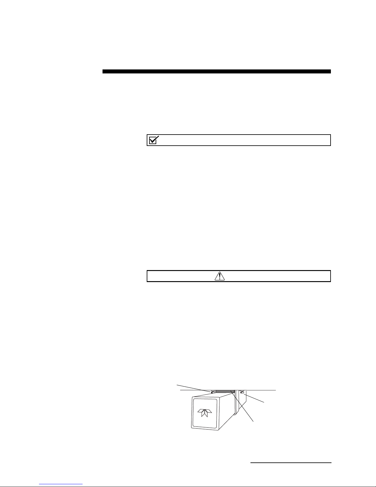
The fraction collector arm is secured to prevent damage during
shipping. The arm securing bracket should be removed at this
time.
1. Loosen the bracket’s two thumbscrews along the sides of
the arm (Figure 2-1).
Figure 2-1 Remove arm stowing bracket and spacer
2-1
ACCQPrep HP125
Note
Note
Section 2 Installation
2.2.1
Pump Installation
2. Push the arm to the left or right to remove the spacer.
3. Store the bracket and spacer. These parts should be reinstalled if the system must be shipped again.
When you are ready to place the system, be sure it is situated in
such a way that the power cord is accessible to disconnect in case
of malfunction.
Be sure to move the two electrical connections and solvent
tubing out of the way before sliding the pump assembly
into the pump compartment.
To install the pump:
1. Remove the two pump retaining screws in the pump compartment.
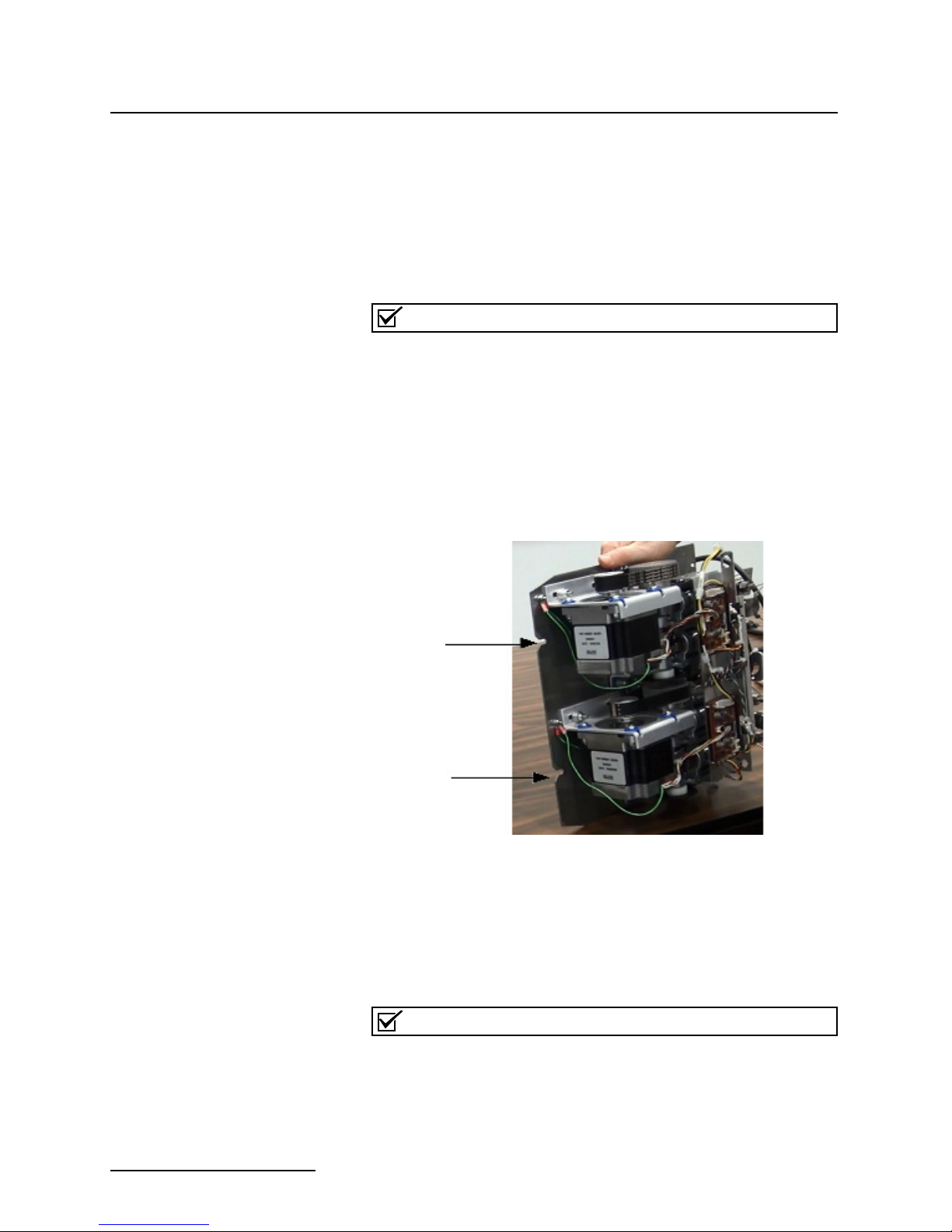
2. Align the pump assembly horizontally with the two notches
facing the opening of the pump compartment (Figure 2-2).
Figure 2-2 Location of notches on the pump sled
2-2
3. Slide the pump assembly into the pump compartment. It
may require a little force since it is metal on metal sliding
together. If the force seems excessive, ensure there is nothing obstructing the pump assembly. Be sure to keep the
electrical connections and tubing out of the way so they do
not get pushed inside of the compartment (Figure 2-3).
Be sure to observe the top of the pump assembly as it is being
inserted into the system. Make sure no wires from the case or
pump assembly are being snagging.
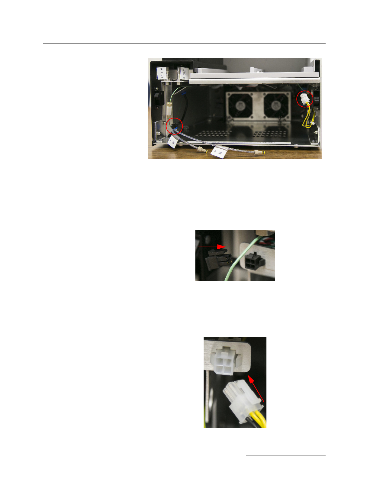
Figure 2-3 Pump compartment with electrical connection
shown
4. When the pump assembly is most of the way in the pump
compartment, connect the electrical connections on each
side of the pump. First, connect the black connection on the
left side. Ensure the tab on top of the connector is facing up
before pushing it into the mating connector (Figure 2-4).
ACCQPrep HP125
Section 2 Installation
Figure 2-4 Black connection with tab facing up
Then, connect the white connection on the right side. Ensure the
tab on top of the connector is facing up before pushing it into the
mating connector (Figure 2-5).
Figure 2-5 White connection with tab facing up
2-3
ACCQPrep HP125
Note
Bulk head unions
Te e Tee
Section 2 Installation
5. Once the electrical connections are complete, push the
pump assembly the rest of the way into the pump compartment until the holes in the front of the pump assembly are
aligned with the corresponding holes in the case bottom.
Hold downs at the back of the pump may cause extra
resistance for the last
6. To hold the pump in place, use the two hex screws,
removed previously, and the hex wrench to secure the
pump assembly (Figure 2-6).
Figure 2-6 Location of threaded holes, in the base of the
unit, and the hex wrench
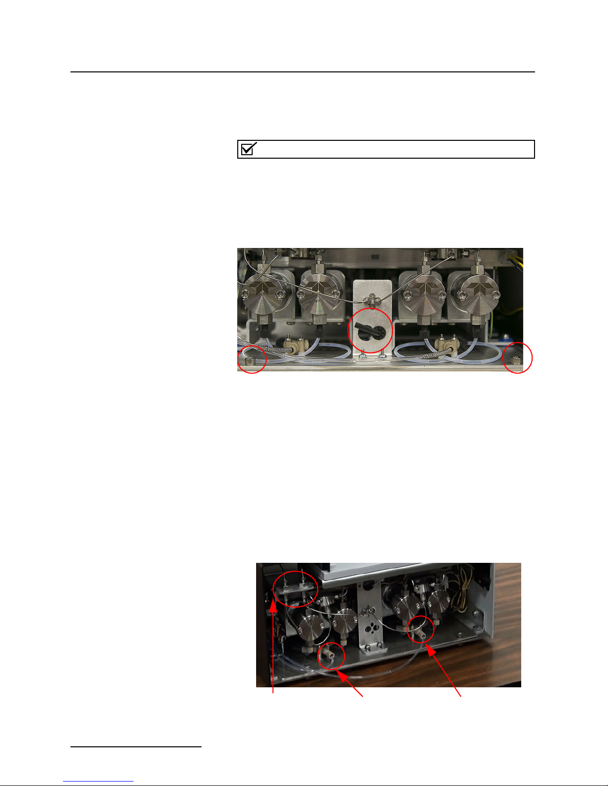
2.2.2 Solvent Line
Installation
1. The left two pump heads form the A solvent pump and the
outlets are connected to a tee. The outlet of this tee connects to the left bulkhead union. Tighten with the
end wrench.
2. The right two pump heads form the B solvent pump and
the outlets are connected to a tee. The outlet tee on this
side is connected to the pressure transducer in the middle
of the assembly. The remaining connector on the pressure
transducer must be connected to the right bulkhead union.
Tighten this fitting with the
2-7).
1
/2” of travel.
1
/4” open
1
/4” open end wrench (Figure
Figure 2-7 Line connections on the pumps
2-4
ACCQPrep HP125
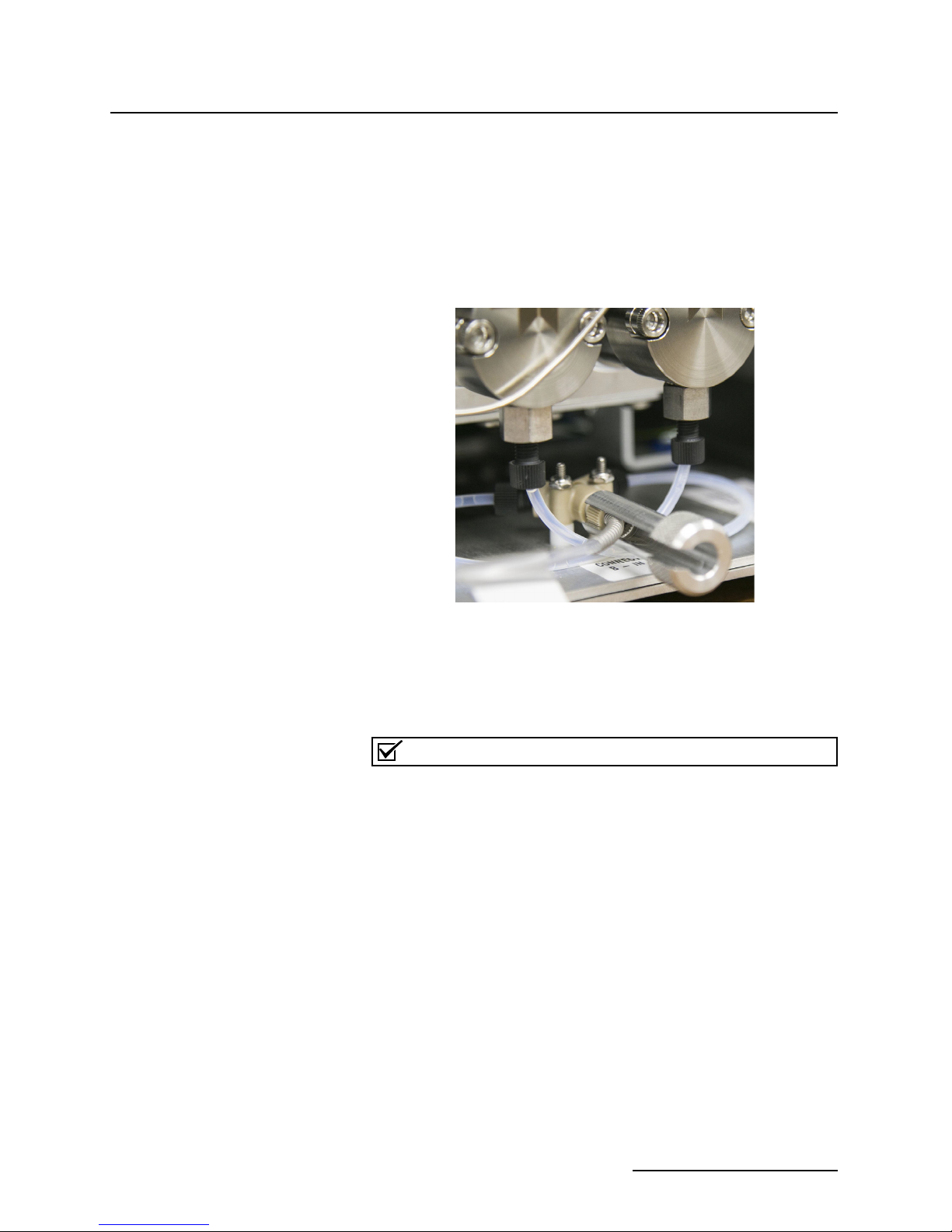
Note
Section 2 Installation
3. Connect the shorter FEP inlet solvent line to the left side
pump’s PEEK tee. Slide the open side of the wrench
(included) over the tubing and FEP fitting and make small
turns as to not bend the tubing (Figure 2-8).
4. Connect the longer FEP inlet solvent line to the right side
pump’s PEEK tee. Slide the open side of the wrench
(included) over the tubing and FEP fitting and make small
turns as to not bend the tubing (Figure 2-8).
Figure 2-8 Wrench used to tighten the FEP inlet line
5. Once complete, install the faceplate onto the unit by snapping the side mounted connectors into place.
2.2.3 Fluid Line Installation
The solvent lines are installed at the factory and include labels
identifying the lines A1, A2, and A3 for the A solvents and line
B1, B2, and B3 for the B solvents when using the Solvent
Selector Valve Module.
1. Remove the two screws that secure the solvent lines for
shipment.
2. Place the solvent lines in the desired containers.
2-5
ACCQPrep HP125
Note
Section 2 Installation
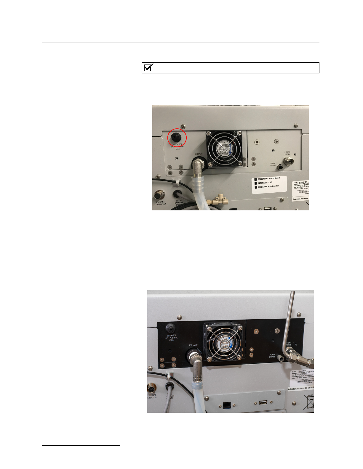
2.2.4 ACCQPrep Equipped
with Optional ELSD
Teledyne ISCO recommends >99% pure nitrogen from a
source that can deliver 2.5 SLPM at 60 to 70 psi.
Figure 2-9 Location of ELSD gas port (Nitrogen input line
circled)
The ACCQPrep ELSD system has several additional connections.
1. Install the ELSD P-trap vent assembly found in the accessory package (PN 3-250004) by placing the short tube into
the port on the rear panel, orienting the vent as shown and
tightening the fitting nut finger tight plus a small amount
more with a wrench (Figure 2-10).
Figure 2-10 Back of ACCQprep with optional ELSD
2-6
ACCQPrep HP125
P-Trap drain vent
assembly drain line
Section 2 Installation
2. ELSD operation requires a carrier gas. To connect the carrier gas to the ACCQPrep:
• Locate the
1
/8 inch O.D. FEP tubing (PN:023-0503-02)
from the accessory package.
• Push one end of the tubing into the NITROGEN INLET
(Figure 2-9) port on the back of the system. The tubing
should be fully seated in the port.
• Cut the tubing to length and connect the other end to
the user-supplied carrier gas. An assortment of
1
/8 inch
adapters are supplied in the accessory kit to complete
the connection to your gas source.
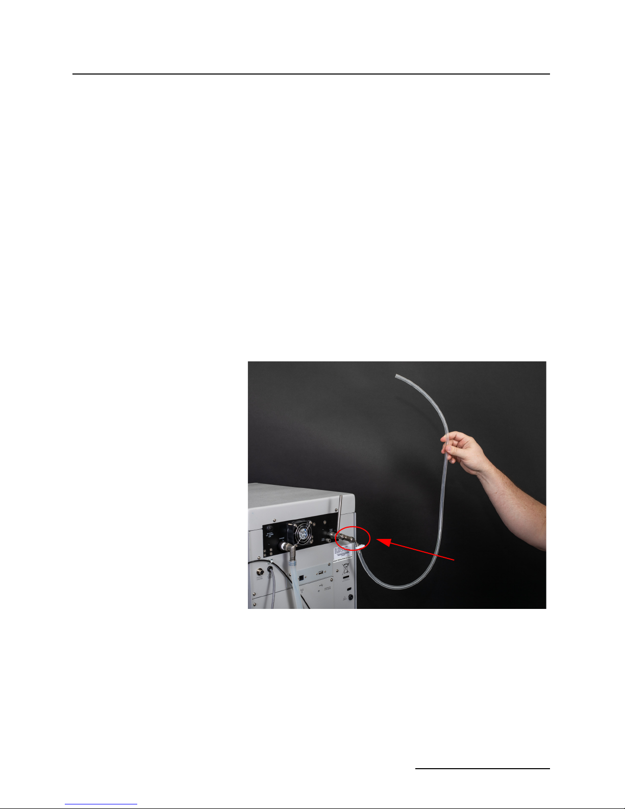
3. The P-trap must be filled with fluid to prevent sample loss.
To accomplish this, raise the drain tubing attached to the
P-trap drain vent assembly above the instrument and
place 10 mL of liquid, such as isopropyl alcohol, into the
tube. Make sure the fluid level in the tubing doesn’t exceed
the level of the instrument case top. If the tubing is raised
too fast, fluid may flow out the top of the vent tube causing
a spill. Lift it high enough so the fluid enters the P-trap
drain (Figure 2-11).
Figure 2-11 Keep liquid level lower than the top of the
system
4. Route the end of the P-trap drain tube to a suitable waste
fluid collection container. Please be aware that as the tubing is lowered, several mL of isopropyl alcohol will run out
of the tubing. This is normal and means that the P-trap is
properly filled. Depending on your application, the P-trap
fluid may need periodic replenishment to ensure maximum
signal strength of the ELSD.
2-7
ACCQPrep HP125
Note
Note
CAUTION
Section 2 Installation
If accessible, the outlet end of the P-trap drain tube may be
used to refill the P-trap.
5. Route the attached tubing from the ELSD exhaust port
away from the system. This will prevent unnecessary solvent vapor alarms.
The ELSD exhaust will contain fine particles of compound. If
using outside of the hood, ensure that the exhaust port tubing
is routed to an exhaust handling system that meets your safety
and environmental requirements. Do not use tubing smaller
than the exhaust tube. If the exhaust is restricted, some of the
gas flow could be diverted out the P trap drain resulting in
reduced sensitivity and the need to route the P trap drain to an
exhaust. In normal operation, the exhaust gas is dry and does
not require a waste collection container.
Discontinue use of the ACCQPrep if liquid is present at the
Pump Drain. Contact Teledyne ISCO technical service for
assistance with correcting the leak.
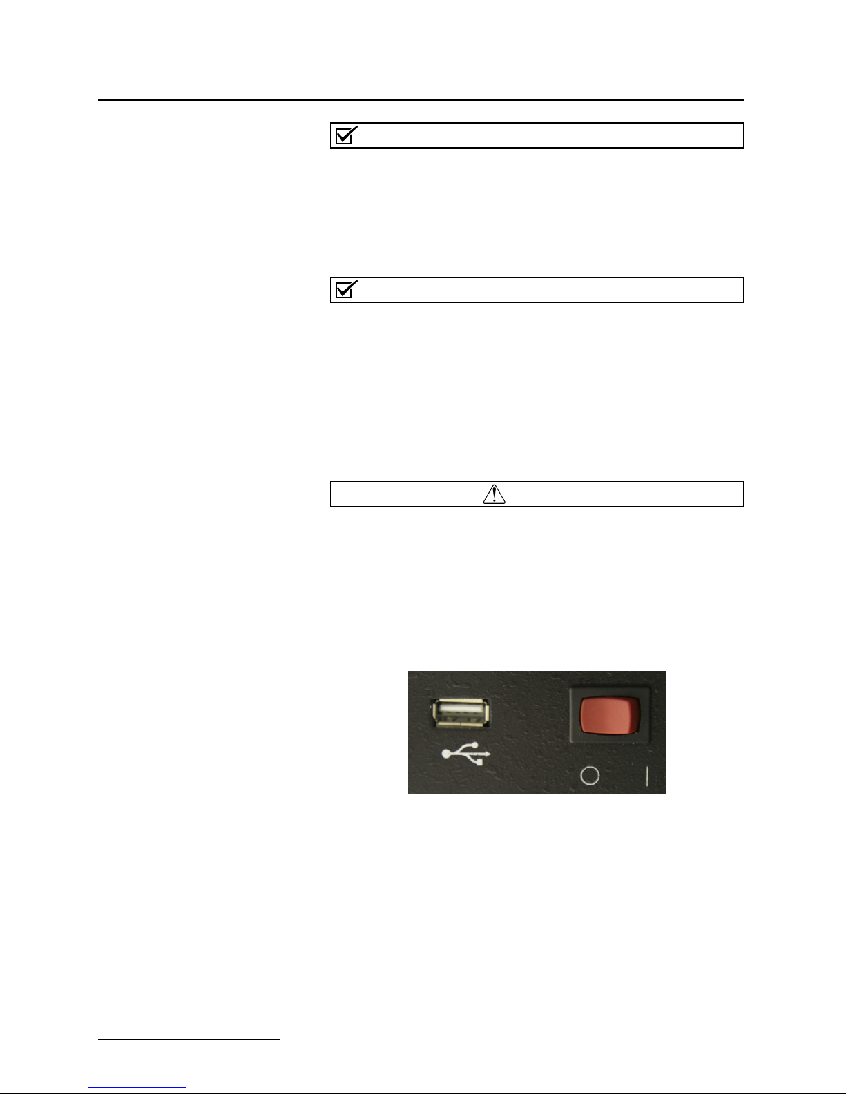
2.2.5 Priming Steps The system will require priming with the desired solvents. To
prime the system:
1. Press the red switch, next to the front USB port, to the O
position to boot up the system (Figure 2-12).
Figure 2-12 Front USB and On switch
2. Turn the prime valve to the P
RIME position (Figure 2-13).
N
2-8
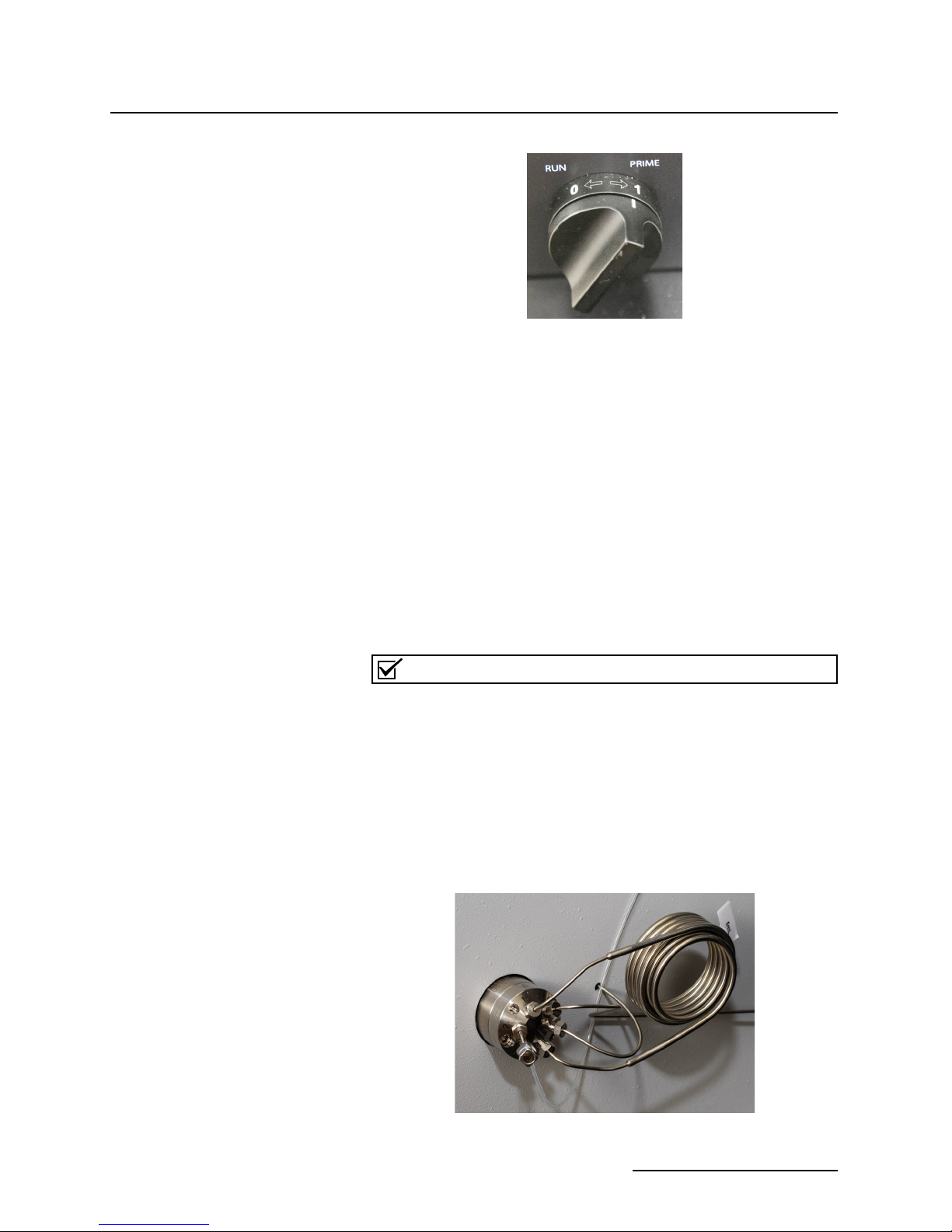
Figure 2-13 Turn the valve to the Prime position
Note
• If the solvent select option is not installed, the system
will immediately prime both solvent lines.
• If the solvent select option is installed, a dialog box
opens when the valve is switched to the P
The dialog box allows you to select which of the A
solvents and B solvents will be primed.
• If you have not already assigned names to the A and B
solvents, they can be named at this time using the drop
downs. If the name you want isn’t listed, it can be added
in the C
completed at a later time.
3. Once priming is complete, a new screen will appear directing you to turn the valve from the P
R
UN position.
ACCQPrep HP125
Section 2 Installation
RIME position.
ONFIGURATION screen. This action can be
RIME position to the
The system will prime both pumps simultaneously. There
is no method to prime A and B individually.
2.3 Installing the Manual
Injection Port
Manual sample injection can be performed with the system even
when equipped with an AutoInjector or AutoSampler.
If no AutoInjector or AutoSampler is installed, a luer injection
port (209900002) is included in the accessory package. To install,
place the fitting into the injection valve and tighten the nut
snugly (Figure 2-14).
Figure 2-14 ACCQPrep with Manual Injection Luer Port installed
2-9
ACCQPrep HP125
Section 2 Installation
Connect the included check valve(209016629) to the inject valve
waste line. Ensure that the arrow on the check valve points
toward the waste container. This check valve ensures sample
doesn’t run from the port when the injection syringe is removed.
If an AutoInjector or AutoSampler is installed and manual
injection is also desired, install the included check valve
(209016629) in the waste line from either the inject valve (if no
AutoInjector or AutoSampler is installed) or the waste line from
the sample load pump. Ensure that the arrow on the check valve
points toward the waste container. This check valve ensures
sample doesn’t run from the port when the injection syringe is
removed.
2.4 Installing the
AutoSampler
These instructions assume that the AutoSampler was purchased
with a new ACCQPrep. In that case, the AutoInjector portion of
the AutoSampler is already installed in the ACCQPrep. If not,
please refer to installation instructions included with the AutoInjector.
To install the AutoSampler:
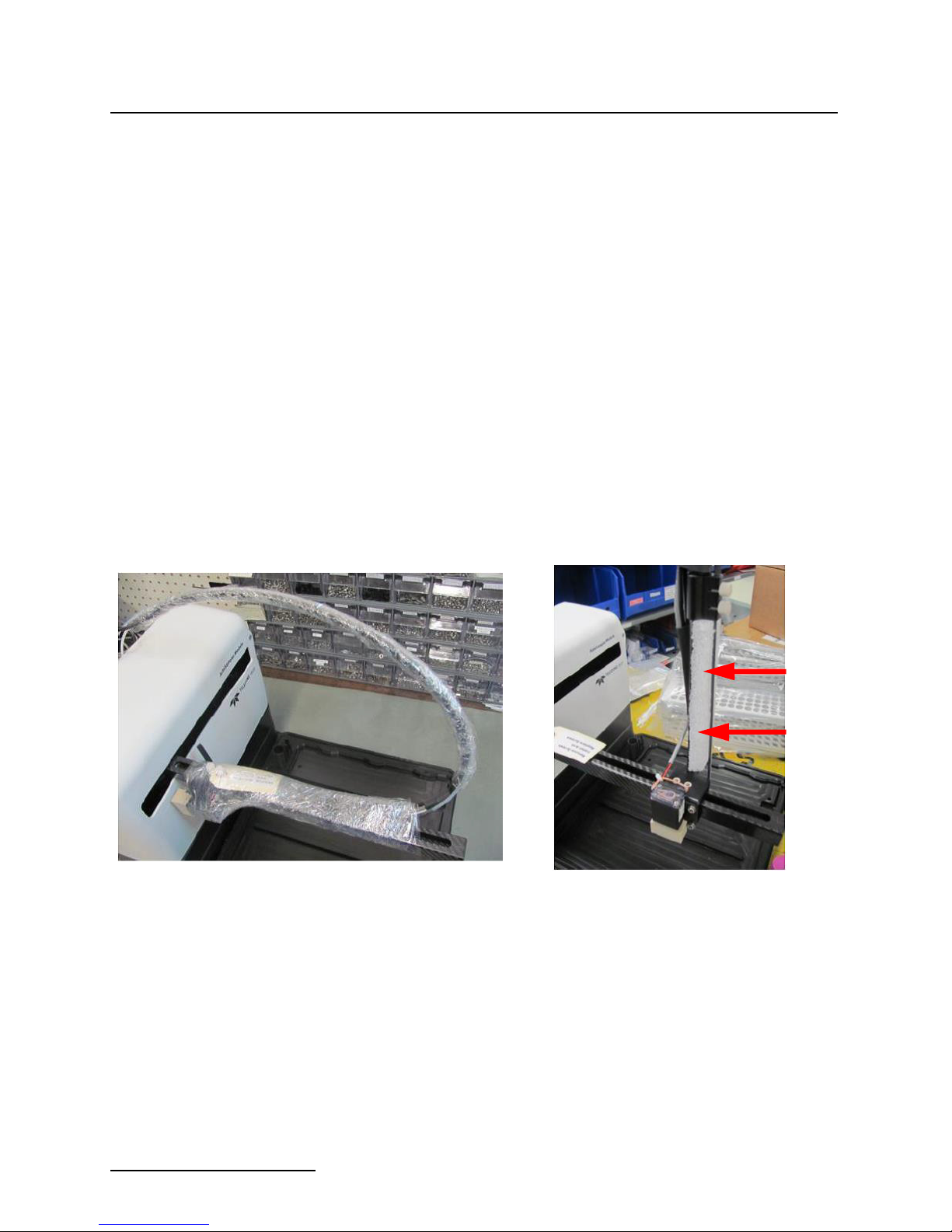
1. Carefully unpack the Z-Drive and remove the packing
materials from the Y-axis arm (Figure 2-15).
Figure 2-15AutoSampler Module and Z-Drive
2-10
2. Find the Y-axis carriage on the arm of the AutoSampler
Module. The Z-Drive will be attached to this carriage (Figure 2-16).
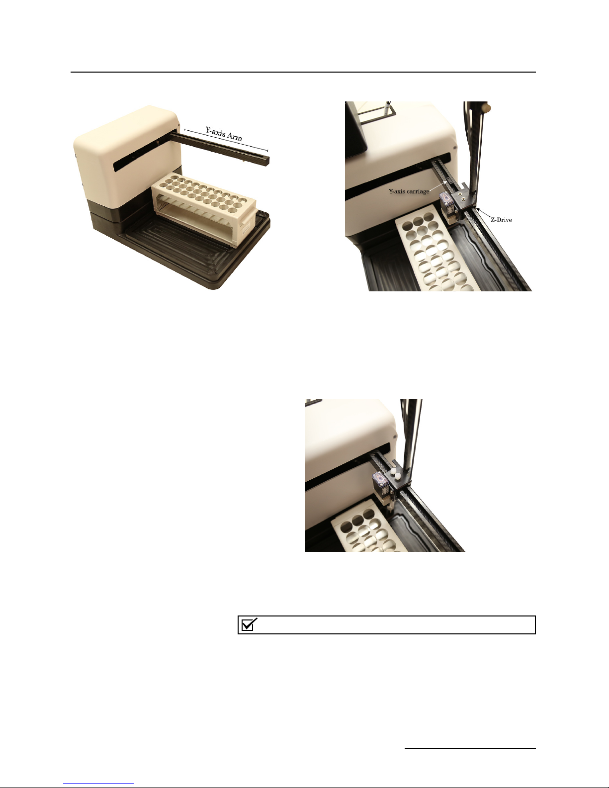
Figure 2-16 Z-Drive mounted on the Y-axis carriage
Note
3. Remove the two screws from the Y axis carriage. Slide the
Z-Drive onto the arm until the two holes align with the
matching holes in the Y-axis carriage.
4. Using the two plastic thumbscrews, secure the Z-Drive to
the carriage and finger tighten (Figure 2-17).
ACCQPrep HP125
Section 2 Installation
Figure 2-17 Z-Drive secured to the Y-axis carriage
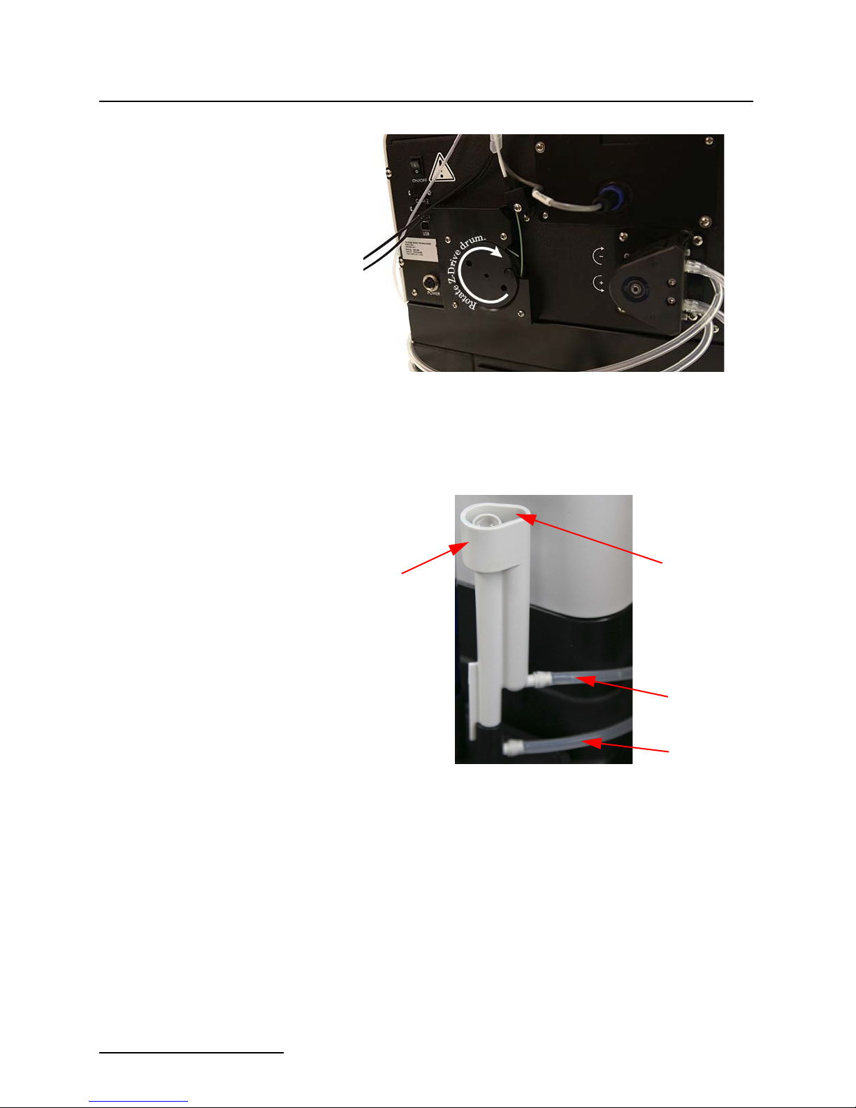
5. Rotate the Z-Drive rotor back and forth to ensure that the
Z-Drive moved up and down freely (Figure 2-18).
If the rotor does not move freely, check that the other cables
are not interfering with the movement of the green probe cable.
2-11
ACCQPrep HP125
Wash station
Overflow drain
Waste line
Wash station
supply line
Section 2 Installation
Figure 2-18 Z-Drive rotation
6. Mount the wash well by placing it into the receptacle
located on the right-rear portion of the AutoSampler Module bed (Figure 2-19).
Figure 2-19 AutoSampler Module wash well with tubing attached (top tube is waste to port #2 while
the bottom tube is supply port #3)
2-12
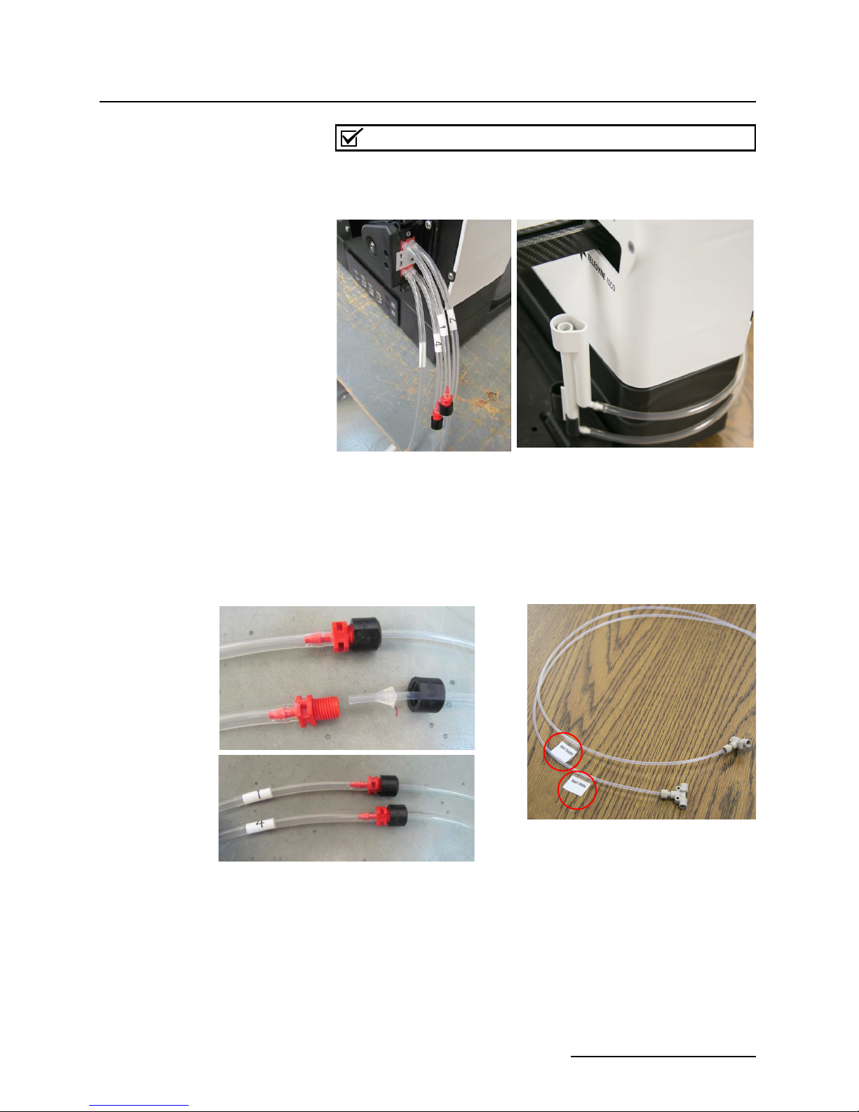
7. The wash well comes pre-plumbed to the peristaltic pump
ports. If disconnected in the future, it is important to connect the wash well waste tube (upper tube on wash well
labeled 2) to port “2” of the peristaltic pump and connect
the wash well supply tube (lower tube on wash well labeled
3) to port 3 of the peristaltic pump.
8. Connect the tube labeled “Wash Supply” to the tube
labeled “1” connected to port “1” of the peristaltic pump on
the back of the Autosampler Module. The free end of the
tubing can be placed in the wash solution container or tee’d
into a solvent supply line (Figure 2-20).
Note
The wash fluid peristaltic pump uses Pharm-A-Line tubing.
Please ensure the wash fluid is compatible with this tubing,
such as methanol.
Figure 2-20 AutoSampler Module peristaltic pump with tubing correctly attached
ACCQPrep HP125
Section 2 Installation
9. Connect the tube labeled “Wash Waste” to the tube labeled
“4” connected to port “4” of the peristaltic pump on the
back of the Autosampler Module. The free end of the tubing can be placed in the waste container or tee’d into an
existing waste line (Figure 2-21).
Figure 2-21 Wash and waste tubing connections and labels
2-13
ACCQPrep HP125
Do not
extend length.
See Step 11
for details.
Section 2 Installation
Auto Sampler Probe
Wash Pump
1 – Wash Inlet
2 – From Wash Station
3 – To Wash Station
4 – Waste
Column Valve
Optional
To Injection
Valve
Auto Injector
Optional
To bottom
column port
External
Detector
Sampler
Sampler
Power
Power
Auto
Auto
USBEthernet
USB
Check Valve
Sampler
Sampler
To
To
Auto
Auto
Waste
Wash Station
Fraction Collection
Solvent Level
Sensing
Solvent Lines
Sample
Not Used
Waste line
Wash station
supply
Needle Wash
Not Normally Used
Needle Wash
Inlet Line
Main
Main
Power
Power
Circuit Breaker
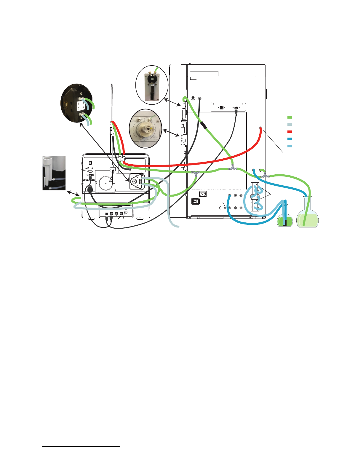
Figure 2-22 Tubing diagram of the AutoSampler connected
to the ACCQPrep (See Appendix A, Figure A-1
for a larger diagram)
10. Place the AutoSampler Module on the right side of the
ACCQPrep.
11. Connect the AutoSampler tubing labeled “To ACCQPrep”
to the connection on the ACCQPrep’s rear panel labeled “To
AutoSampler”. The length of this tubing is critical to control the delay volume for fraction collection on the AutoSampler. The overall length of the tubing to the diverter
valve should be 67” (170 cm).
12. Route the “To Waste” tubing to a suitable waste container
or tee to either the Wash Waste Line from the AutoSampler Module (from step 8 above or seen in Figure 2-22)
and/or the ACCQPrep waste line and injection valve waste
line with the supplied tee(s).
Optional
External Gas
Not Normally Used
Drain
Drain
A1 A2 A3
A1 A2 A3
Solvent Level Sensing
Solvent Level Sensing
B1 B2 B3
B1 B2 B3
Waste
Waste
Level
Level
Waste
Waste
Sense
Sense
Solvent Inlet
Solvent Inlet
J
A1
A1
A2
A2
A3
B
A
B
A
IN
IN
IN
IN
B3
B3
B1
B1
B2
B2
B4
B4
Repeat tubing for A1 Solvent as needed
Solvent inlet
valves
optional
If not used,
connect directly
to A and B
A1 Solvent
WASTE
2-14
 Loading...