

Page 1
Getting Started
Manual
LabMaster 9 Zi-A
Oscilloscopes
Page 2

Page 3

LabMaster 9 Zi-A Oscilloscopes
Getting Started Manual
May, 2013
Page 4

© 2013 Teledyne LeCroy, Inc. All rights reserved.
Unauthorized duplication of Teledyne LeCroy documentation materials other than for
internal sales and distribution purposes is strictly prohibited. However, clients are
encouraged to distribute and duplicate Teledyne LeCroy documentation for their own
internal educational purposes.
LabMaster and Teledyne LeCroy are registered trademarks of Teledyne LeCroy, Inc.
Windows is a registered trademark of Microsoft Corporation. Other product or brand names
are trademarks or requested trademarks of their respective holders. Information in this
publication supersedes all earlier versions. Specifications are subject to change without
notice.
Warranty
NOTE: THE WARRANTY BELOW REPLACES ALL OTHER WARRANTIES, EXPRESSED OR IMPLIED,
INCLUDING BUT NOT LIMITED TO ANY IMPLIED WARRANTY OF MERCHANTABILITY, FITNESS,
OR ADEQUACY FOR ANY PARTICULAR PURPOSE OR USE. TELEDYNE LECROY SHALL NOT BE
LIABLE FOR ANY SPECIAL, INCIDENTAL, OR CONSEQUENTIAL DAMAGES, WHETHER IN
CONTRACT OR OTHERWISE. THE CUSTOMER IS RESPONSIBLE FOR THE TRANSPORTATION
AND INSURANCE CHARGES FOR THE RETURN OF PRODUCTS TO THE SERVICE FACILITY.
TELEDYNE LECROY WILL RETURN ALL PRODUCTS UNDER WARRANTY WITH TRANSPORT
PREPAID.
The oscilloscope is warranted for normal use and operation, within specifications, for a
period of three years from shipment. Teledyne LeCroy will either repair or, at our option,
replace any product returned to one of our authorized service centers within this period.
However, in order to do this we must first examine the product and find that it is defective
due to workmanship or materials and not due to misuse, neglect, accident, or abnormal
conditions or operation.
Teledyne LeCroy shall not be responsible for any defect, damage, or failure caused by any of
the following: a) attempted repairs or installations by personnel other than Teledyne LeCroy
representatives or b) improper connection to incompatible equipment, or c) for any damage
or malfunction caused by the use of non-Teledyne LeCroy supplies. Furthermore, Teledyne
LeCroy shall not be obligated to service a product that has been modified or integrated
where the modification or integration increases the task duration or difficulty of servicing
the oscilloscope. Spare and replacement parts, and repairs, all have a 90-day warranty.
The oscilloscope's firmware has been thoroughly tested and is presumed to be functional.
Nevertheless, it is supplied without warranty of any kind covering detailed performance.
Products not made by Teledyne LeCroy are covered solely by the warranty of the original
equipment manufacturer.
922157-00 Rev A
May 2013
Page 5

Getting Started Manual
922157-00 Rev A
i
TABLE OF CONTENTS
Welcome .............................................................................................................. 1
Safety Instructions................................................................................................ 2
LabMaster Overview ............................................................................................ 8
Master Control Module Configuration .............................................................. 9
Master Acquisition Module Configuration ...................................................... 10
Front of MCM-Zi Master Control Module ........................................................ 11
Back of MCM-Zi Master Control Module ......................................................... 12
Front of 9CZi-A Master Control Module .......................................................... 13
Back of 9CZi-A Master Control Module ........................................................... 14
Front of 9xxMZi-A Master Acquisition Module ................................................ 16
Back of 9xxMZi-A Master Acquisition Module ................................................. 17
Front of CPU Module ....................................................................................... 18
Back of CPU Module ........................................................................................ 19
Input/Output Panel .......................................................................................... 20
Front of 9xxSZi-A Slave Acquisition Module .................................................... 22
Back of 9xxSZi-A Slave Acquisition Module ..................................................... 23
ChannelSync Mainframe Hub .......................................................................... 24
LabMaster Hardware Set Up .............................................................................. 25
Overview .......................................................................................................... 25
LabMaster Setup Styles .................................................................................... 25
9CZi-A Master Control Module Configuration ................................................. 27
MCM-Zi Master Control Module Configuration ............................................... 38
9xxMZi-A Master Acquisition Module Configuration ...................................... 46
Removing and Attaching the Front Panel Control ........................................... 59
Touch Screen and External Displays ................................................................ 61
Signal Inputs ....................................................................................................... 64
Interfaces ......................................................................................................... 64
ProLink Interface Adapters .............................................................................. 67
ProLink Probe Adapters ................................................................................... 68
Probe Dialog ..................................................................................................... 69
Passive Probe Compensation ........................................................................... 71
Front Panel ......................................................................................................... 72
Miscellaneous Controls and WaveStream Indicator ........................................ 73
Trigger Controls ............................................................................................... 74
Horizontal Controls .......................................................................................... 75
Page 6

LabMaster 9 Zi-A
ii
922157-00 Rev A
Vertical Controls .............................................................................................. 76
Zoom and Math Controls ................................................................................. 77
Display Dashboard .............................................................................................. 78
Screen Layout, Groupings, and Controls ......................................................... 78
Menu Bar ......................................................................................................... 79
Quick Access Toolbar ....................................................................................... 79
Signal Display Grid ........................................................................................... 81
Trace Descriptor Labels ................................................................................... 83
Shortcut Buttons .............................................................................................. 85
Annotating Traces ............................................................................................ 85
Dialog Area ...................................................................................................... 87
Shortcut Buttons .............................................................................................. 92
Message Bar .................................................................................................... 93
Turning on Channels and Traces ......................................................................... 94
Timebase ............................................................................................................ 95
Timebase Overview ......................................................................................... 95
Combining Channels ........................................................................................ 95
Timebase Setup and Control ........................................................................... 99
Sampling Modes ............................................................................................... 100
Sampling Modes Overview ............................................................................ 100
Selecting a Sampling Mode............................................................................ 100
Single-shot Sampling Mode ........................................................................... 100
Sequence Sampling Mode – Working with Segments ................................... 101
RIS Sampling Mode - For Higher Sampling Rates........................................... 108
Roll Mode ...................................................................................................... 110
Vertical ............................................................................................................. 111
Channel Controls ........................................................................................... 111
Shortcut Buttons ............................................................................................ 114
Pre-Processing Controls ................................................................................. 115
LabMaster 9 Zi-A Channel Setup ................................................................... 119
LabMaster De-Skew Calibration .................................................................... 120
Trigger .............................................................................................................. 127
Trigger Types ................................................................................................. 128
Trigger Settings .............................................................................................. 133
Trigger Setup ................................................................................................. 134
TriggerScan .................................................................................................... 141
Page 7

Getting Started Manual
922157-00 Rev A
iii
Viewing Waveforms ......................................................................................... 145
Display ............................................................................................................ 145
Persistence ..................................................................................................... 148
WaveStream Display Mode............................................................................ 150
Adjusting Trace Intensity ............................................................................... 151
Zooming Waveforms ........................................................................................ 153
Zooming Waveforms Overview ..................................................................... 153
Zooming a Single Channel .............................................................................. 154
Touch-and-Drag Zooming .............................................................................. 156
Quickly Zooming Waveforms ......................................................................... 156
Turning Off Zoom ........................................................................................... 156
Measuring with Cursors .................................................................................... 157
Quickly Displaying Cursors ............................................................................. 157
Cursor Setup .................................................................................................. 158
Cursors on Math Functions ............................................................................ 159
Measurement Parameters ................................................................................ 160
Turning On Parameters .................................................................................. 160
Quick Access to Parameter Setup Dialogs ..................................................... 160
Parameter Setup ............................................................................................ 161
Measure Modes ............................................................................................. 162
Help Markers.................................................................................................. 163
Analysis ............................................................................................................ 166
Histogram ....................................................................................................... 168
Creating and Viewing a Trend ........................................................................ 174
Creating a Track View .................................................................................... 175
Pass-Fail Parameter Testing ........................................................................... 176
Math ................................................................................................................ 185
Math Traces and Functions Overview............................................................ 185
Math Setup .................................................................................................... 186
Mask Testing .................................................................................................... 188
Creating a Mask ............................................................................................. 188
Quick Access to Pass/Fail Setup Dialogs ........................................................ 189
Removing a Mask from the Display ............................................................... 190
Right-Hand Dialogs ......................................................................................... 191
WaveScan Overview ......................................................................................... 192
Signal Views ................................................................................................... 193
Search Modes ................................................................................................ 193
Page 8

LabMaster 9 Zi-A
iv
922157-00 Rev A
Parameter Measurements ............................................................................. 194
Sampling Mode .............................................................................................. 194
Customization Overview ................................................................................... 195
Documenting Your Work Using LabNotebook ................................................... 196
LabNotebook ................................................................................................. 197
Save/Recall ....................................................................................................... 201
Saving and Recalling Setups ........................................................................... 202
Saving and Recalling Waveforms ................................................................... 203
Utilities ............................................................................................................. 207
Utilities ........................................................................................................... 207
Status ............................................................................................................. 209
Remote Communication ................................................................................ 209
Printing and Hardcopy Functions .................................................................. 211
Aux Output .................................................................................................... 217
Date/Time ...................................................................................................... 219
Options .......................................................................................................... 220
Disk Utilities ................................................................................................... 220
Preferences .................................................................................................... 222
Acquisition ..................................................................................................... 223
Acquisition Status .......................................................................................... 224
E-Mail ............................................................................................................. 225
Color .............................................................................................................. 226
Miscellaneous ................................................................................................ 227
System Recovery Tool ....................................................................................... 228
Running the Acronis True Image Echo Workstation Recovery Application ... 229
Restarting the Application ............................................................................. 232
Restarting the Operating System ................................................................... 232
Reference ......................................................................................................... 233
Specifications ................................................................................................. 233
Certifications .................................................................................................. 233
Contact Teledyne LeCroy ............................................................................... 237
X-Stream® Software End-User License Agreement ........................................ 238
Windows® License Agreement ....................................................................... 248
Index ................................................................................................................. 249
Page 9

Getting Started Manual
922157-00 Rev A
1
Welcome
Thank you for purchasing a Teledyne LeCroy product. We're certain you'll
be pleased with the detailed features so unique to our instruments.
This LabMaster 9 Zi-A Getting Started Manual is designed to cover
important safety and installation information for your oscilloscope, along
with standard procedures so you're quickly working on waveforms. The
Teledyne LeCroy website at teledynelecroy.com maintains the most current
specification information and the online help file on your instrument may
be accessed for more comprehensive documentation. Sections of the
online help residing on your oscilloscope may be printed and transferring
the help file itself to a USB memory device is a fairly common procedure.
Details on how to access your online help file can be found in a .pdf file on
the desktop of your oscilloscope.
This manual is arranged in the following manner:
Physical features such as hardware, basic controls, display
Core oscilloscope functions such as timebase and vertical setup
Special features such as customization, LabNotebook, Save/Recall
(File) functions, and Utilities
Reference, including certifications and contact information
When your product is delivered, verify that you’ve received all items on the
packing list or invoice copy. Contact your nearest Teledyne LeCroy
customer service center or national distributor if anything is missing or
damaged. We can only be responsible for replacement if you contact us
immediately.
We truly hope you enjoy using Teledyne LeCroy's fine products.
Sincerely,
David C. Graef
Teledyne LeCroy Corporation
Vice President and Chief Technology Officer
Page 10
LabMaster 9 Zi-A
2
922157-00 Rev A
CAUTION of damage to instrument, or WARNING of hazard to
health. Attend to the accompanying information to protect
against personal injury or damage. Do not proceed until
conditions are fully understood and met.
WARNING. High Voltage. Risk of electric shock.
Measurement ground connection.
Safety (protective) ground connection.
Alternating Current.
Standby Power (front of 9CZi-A, MCM-Zi, and 9xxMZi-A).
Power On (back of 9xxMZi-A); connected to AC mains.
Power Off (back of 9xxMZi-A); disconnected from AC mains.
Safety Instructions
This section contains instructions that must be observed to keep the
instrument operating in a correct and safe condition. You are required to
follow generally accepted safety procedures in addition to the precautions
specified in this section. The overall safety of any system incorporating
this instrument is the responsibility of the assembler of the system.
Symbols
These symbols appear on the instrument's front or rear panels and in
documentation to alert you to important safety considerations.
Page 11

Getting Started Manual
922157-00 Rev A
3
Precautions
Use proper power cord. Use only the power cord shipped with this
instrument and certified for the country of use.
Maintain ground. This product is grounded through the power cord
grounding conductor. To avoid electric shock, connect only to a grounded
mating outlet.
Connect and disconnect properly. Do not connect/disconnect probes or
test leads while they are connected to a voltage source.
Observe all terminal ratings. Do not apply a voltage to any input (C1, C2,
C3, C4 or EXT) that exceeds the maximum rating of that input. Refer to the
front of the oscilloscope for maximum input ratings.
Use only within operational environment listed. Do not use in wet or
explosive atmospheres.
Use indoors only.
Keep product surfaces clean and dry.
Do not block the cooling vents. Leave a minimum six-inch (15 cm) gap
between the instrument and the nearest object. Keep the underside clear
of papers and other objects.
Do not remove the covers or inside parts. Refer all maintenance to
qualified service personnel.
Do not operate with suspected failures. Do not use the product if any part
is damaged. Obviously incorrect measurement behaviors (such as failure to
calibrate) might indicate impairment due to hazardous live electrical
quantities. Cease operation immediately and sequester the instrument
from inadvertent use.
Operating Environment
Temperature: 5 to 40 °C.
Humidity: Maximum relative humidity 80 % for temperatures up to 31 °C
decreasing linearly to 50 % relative humidity at 40 °C (or at the upper
operational temperature limit).
Altitude: Up to 10,000 ft (3,048 m) at or below 25 °C.
Page 12

LabMaster 9 Zi-A
4
922157-00 Rev A
Cooling
The instrument relies on forced air cooling with internal fans and vents.
Take care to avoid restricting the airflow to any part of the oscilloscope.
Around the sides and rear, leave a minimum of 15 cm (6 inches) between
the instrument and the nearest object. At the bottom, the oscilloscope feet
(up or down) provide adequate clearance.
CAUTION. Do not block oscilloscope vents. Always keep the area beneath
the oscilloscope clear of paper and other items.
The instrument also has internal fan control circuitry that regulates the fan
speed based on the ambient temperature. This is performed automatically
after start-up.
Cleaning
Clean only the exterior of the oscilloscope using a damp, soft cloth. Do not
use harsh chemicals or abrasive elements. Under no circumstances
submerge the instrument or allow moisture to penetrate it. Avoid electric
shock by unplugging the power cord from the AC outlet before cleaning.
CAUTION. Do not attempt to clean internal parts. Refer to qualified service
personnel.
Calibration
The oscilloscope is calibrated at the factory prior to being shipped. The
recommended calibration interval is one year. Calibration should be
performed by qualified personnel only.
The oscilloscope software includes automatic and user-initiated deskew
calibration functions.
Schedule an annual factory calibration as part of your regular maintenance.
Extended warranty, calibration, and upgrade plans are available for
purchase. Contact your Teledyne LeCroy sales representative or
customersupport@teledynelecroy.com to purchase a service plan.
Page 13

Getting Started Manual
922157-00 Rev A
5
Power
AC Power Source
100 to 240 VAC (+/-10%) at 50/60 Hz (+/-10%)
Manual voltage selection is not required because the instrument
automatically adapts to line voltage.
Power Consumption
9XXMZI-A MASTER ACQUISITION MODULE
13-20 GHz Models
Max Power Consumption (all accessories installed): ≤ 850 watts (850 VA)
Power consumption in Standby Mode: 10 Watts.
30-45 GHz DBI Models
Max Power Consumption (all accessories installed): ≤ 900 watts (900 VA)
Power consumption in Standby Mode: 10 Watts.
CPU MODULE - INCLUDED WITH LABMASTER 9XXMZI-A
Max Power Consumption (all accessories installed): ≤ 400 watts (400 VA)
Power consumption in Standby Mode: 5 Watts.
9CZI-A MASTER CONTROL MODULE
Max Power Consumption (all accessories installed): ≤ 450 watts (450 VA)
Power consumption in Standby Mode: 5 Watts.
MCM-ZI MASTER CONTROL MODULE
Max Power Consumption (all accessories installed): ≤ 450 watts (450 VA)
Power consumption in Standby Mode: 5 Watts.
9XXSZI-A SLAVE ACQUISITION MODULE
13-20 GHz Models
Max Power Consumption (all accessories installed): ≤ 700 watts (700 VA)
Power consumption in Standby Mode: 12 Watts.
30-45 GHz Models
Max Power Consumption (all accessories installed): ≤ 750 watts (750 VA)
Power consumption in Standby Mode: 12 Watts.
Page 14

LabMaster 9 Zi-A
6
922157-00 Rev A
Power and Ground Connections
The 9xxMZi-A Master Acquisition Module is provided with a 15A/250V
14AWG rated grounded cord set containing a molded three-terminal
polarized plug and a specific IEC-60320 (Type C15) connector for making
line voltage and safety ground connections.
The 9CZi-A and MCM-Zi Master Control Modules , 9xxSZi-A Acquisition
Module, and the CPU Module are provided with standard 10A/250V
18AWG rated grounded cord sets with IEC320 right-angle Type C13
connectors.
The AC inlet ground is connected directly to the frame of the instrument.
For adequate protection again electric shock, connect to a mating outlet
with a safety ground contact.
WARNING. Interrupting the protective conductor inside or outside the
oscilloscope, or disconnecting the safety ground terminal, creates a
hazardous situation. Intentional interruption is prohibited.
Standby Power
The Standby (Power) button controls the operational state of the Master
Control Module (LabMaster 9CZi-A or MCM-Zi), the Master Acquisition
Module (LabMaster 9xx-MZi-A), and the CPU Module.
Press the button to switch the instrument into Standby mode
(reduced power); press it again to return to full operation.
Press and hold the button for 5 seconds to power off the
instrument.
On the 9CZi-A Master Control Module, the color of the LED below the
Standby button indicates the operational state of the oscilloscope:
Steady green – fully powered and operational
Blinking green – computer subsystems on Standby (reduced
power); all other subsystems fully powered.
Off – powered off except for some housekeeping circuits.
On the MCM-Zi Master Control Module, LED indicator will be either:
Blue– fully powered and operational.
Off– powered off except for some housekeeping circuits.
Page 15

Getting Started Manual
922157-00 Rev A
7
Always use the Standby button or the File > Shutdown menu option to
execute a proper shut down process and preserve settings before powering
down. Do not shut down by pulling the power cord from the socket or
shutting off a connected power strip.
The Standby button does not disconnect the oscilloscope from the AC
power supply. The only way to fully power down the instrument is to use
the rear Power switch (if available), or unplug the AC power cord from the
outlet.
We recommend unplugging the instrument if it will be unused for a long
period of time.
CAUTION. Do not change the instrument’s Windows Power Options setting
from the default Never to System Standby or System Hibernate. Doing so
can cause the system to fail.
Page 16

LabMaster 9 Zi-A
8
922157-00 Rev A
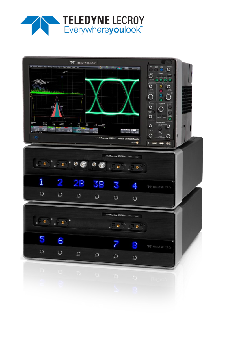
LabMaster Overview
LabMaster is a unique modular oscilloscope solution that allows a
configuration of more channels at higher bandwidths than traditional four
channel oscilloscopes. It is ideally suited for test situations where there are
many lanes of serial data to be captured and analyzed simultaneously,
where crosstalk analysis is performed, or for capturing four channels at the
highest-possible bandwidths for optical coherent modulation applications.
Each LabMaster consists of a single Master Acquisition Module or Master
Control Module, and optional additional Slave Acquisition Modules. Slaves
can be added at any time for easy channel upgrades. Bandwidth upgrades
are available for both Master Acquisition Modules and Slave Acquisition
Modules for future scalability.
Unique ChannelSync™ architecture ensures precise synchronization
between all oscilloscope channels located in different acquisition modules.
A single 10 GHz distributed clock signal is generated in the Master
Acquisition Module or Master Control Module, and then used in or
distributed to as many as five Master Acquisition Modules or Slave
Acquisition Modules. The 10 GHz clock frequency - 1000 times faster than
the 10 MHz reference clocks commonly used to synchronize lab equipment
- ensures precise synchronization and high-timebase accuracy between all
acquisition modules. Additionally, a single trigger signal is used for all
acquisition modules to completely eliminate trigger jitter between
modules, such as would be found when two conventional oscilloscopes are
synchronized with 10 MHz clocks and a common trigger signal. The system
also ensures Acquisition Modules are automatically identified to the
Master, and software de-skew calibration routines allow for fast calibration
and correction for any static acquisition skew between all acquisition
modules.
NOTE: Detailed steps explaining how to set up either configuration are covered in
Configuration Setups Overview (on page 25).
Page 17
Getting Started Manual
922157-00 Rev A
9
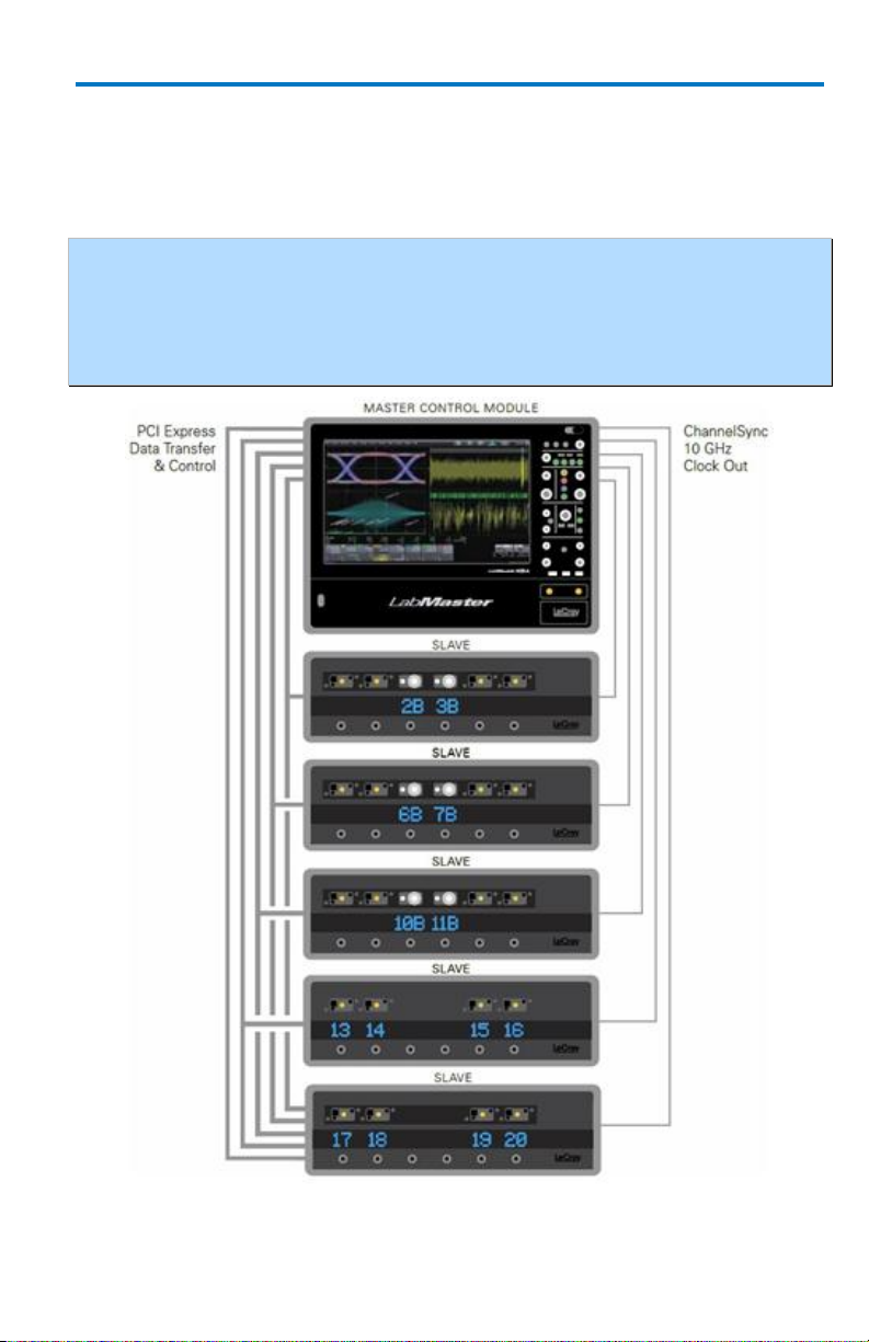
Master Control Module Configuration
This configuration includes either a 9CZi-A Master Control Module or
MCM-Zi Master Control Module with up to five Slave Acquisition
Modules.
NOTE: If your LabMaster system runs multiple Slave Acquisition Modules, for
optimal channel access and convenience, we recommend stacking the modules on
top of each other on your bench, inside Teledyne LeCroy's OC910 Oscilloscope
Cart, or inside of your own rack (modules must be specifically ordered for rack
mounting from the Teledyne LeCroy factory).
9CZi-A Master Control Module with up to five 9xxSZi-A Slave Acquisition Modules
Page 18
LabMaster 9 Zi-A
10
922157-00 Rev A
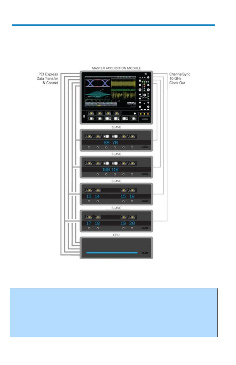
Master Acquisition Module Configuration
This configuration includes a 9xxMZi-A Master Acquisition Module with
corresponding CPU Module, and up-to-four 9xxSZi-A Slave Acquisition
Modules.
9xxMZi-A Master Acquisition Module with CPU Module and
four 9xxSZi-A Slave Acquisition Modules
NOTE: The 9xxSZi-A Slave Acquisition Modules are available in a variety of
bandwidths and channel density configurations. Each example shown previously
contains a mix of 20 GHz and >20 GHz Slave Acquisition Modules. Each Slave
Acquisition Module is compatible with either Master Module (Control or
Acquisition). Refer to specifications on the datasheet maintained at
teledynelecroy.com, or contact your Teledyne LeCroy representative for details.
Page 19
Getting Started Manual
922157-00 Rev A
11
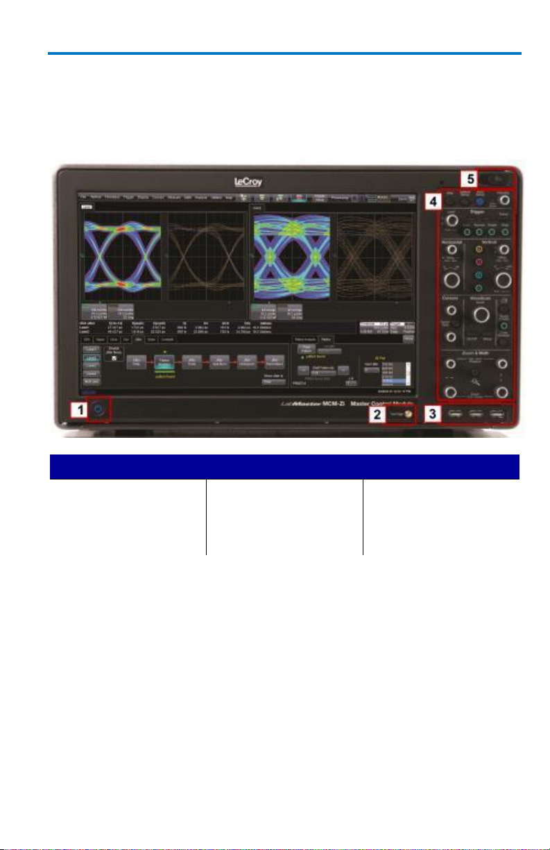
Number and Description
1. Power Button
2. Fast Edge Output
3. Host USB Ports
4. Detachable Front
Panel Control
5. Front Panel Control
Release Switch
Front of MCM-Zi Master Control Module
The MCM-Zi Master Control Module includes Controls, Display, CPU, and
ChannelSync Clock Architecture. All acquisition capability is contained in
separate Acquisition Modules.
Page 20
LabMaster 9 Zi-A
12
922157-00 Rev A
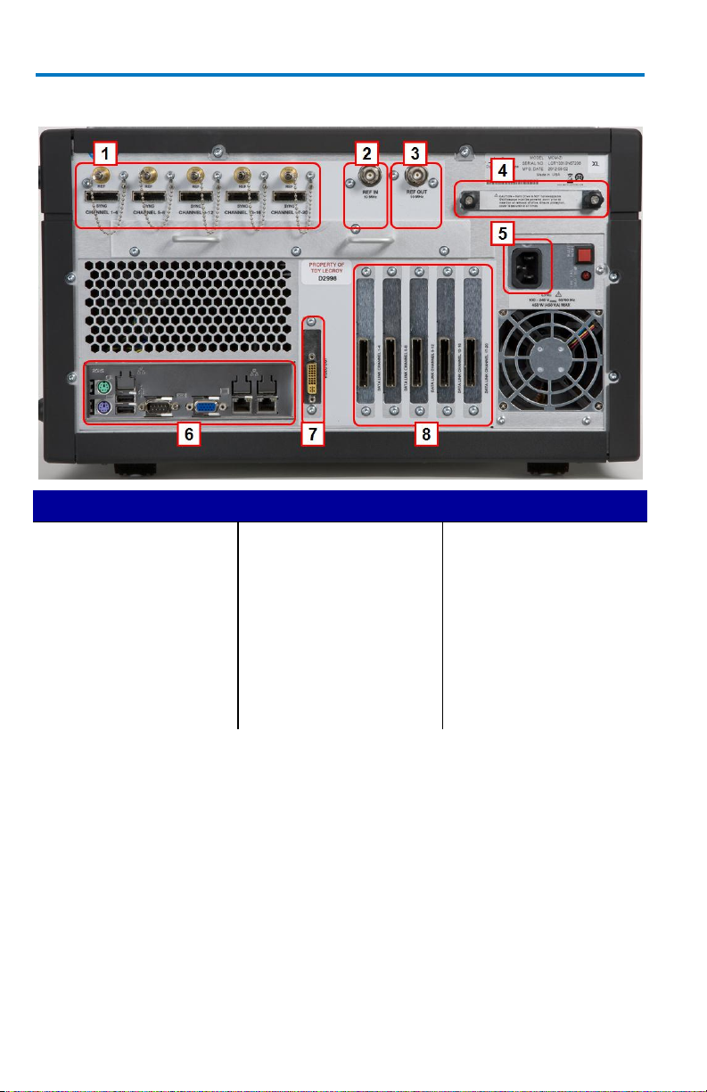
Number and Description
1. ChannelSync Outputs
- SMA 10 GHz Clock
and PCIe 1 Lane
Control Connections
(for corresponding
Acquisition Modules)
2. 10 MHz Reference
Clock Output
3. 10 MHz Reference
Clock Input
(Grounded EMI Shield
required when port is
not in use)
4. Removable Storage
Drive
5. AC Power Inlet
6. Input/Output Panel
7. DVI-D Video Output
8. PCIe 4 Lane Data
Inputs (from
corresponding
Acquisition Modules)
Back of MCM-Zi Master Control Module
PLEASE NOTE THE FOLLOWING:
Cap-off unused ChannelSync SMA sockets (item 1) using the provided
chain-linked 50 Ω terminations (not shown).
10 MHz Reference Clock Inputs are specifically intended for
synchronization with other instruments; not between Master Control
Module and Acquisition Modules.
DVI-D Video Output is for use with an additional external monitor for
Extended Desktop mode.
The AUX IN connection is for 50 Ω input only.
Page 21
Getting Started Manual
922157-00 Rev A
13
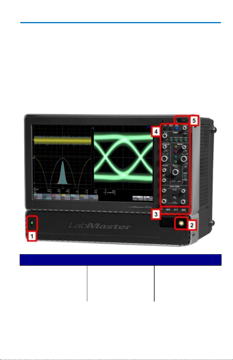
Number and Description
1. Power Button
2. Fast Edge Output
3. USB Ports
4. Detachable Front
Panel Control
5. Front Panel Control
Release Switch
The PCIe 4 Lane Data Inputs (item 8) also accommodate PCIe Expansion
Slot options for GPIB and LSIB. Option cards must be specified when
ordering and installed at the Teledyne LeCroy factory into any number of
the same five slots used for the Acquisition Modules. The slot between
the DVI-D Video Output connector and the PCIe 4 Lane Data Connection
for Channels 1-4 is unavailable.
Front of 9CZi-A Master Control Module
The 9CZi-A Master Control Module includes Controls, Display, CPU, and
ChannelSync Clock Architecture. All acquisition capability is contained in
separate Slave Acquisition Modules.
Page 22
LabMaster 9 Zi-A
14
922157-00 Rev A
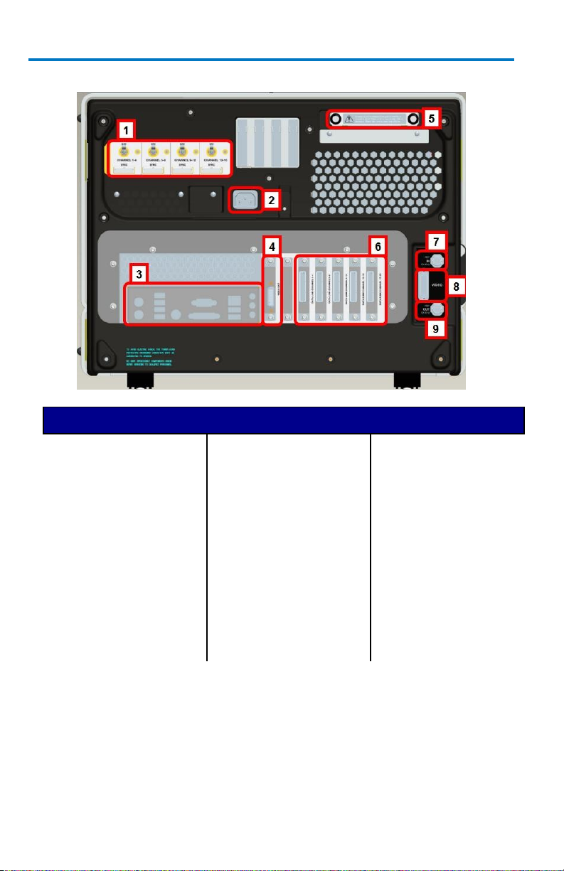
Number and Description
1. Channel Sync Outputs
- SMA 10 GHz Clock
and PCIe 1 Lane
Control Connections
(for corresponding
Slave Acquisition
Modules)
2. AC Power Plug
3. Input/Output Panel
(on page 20)
4. DVI-D Video Output
5. Removable Hard
Drive
6. PCIe 4 Lane Data
Inputs (from
corresponding Slave
Acquisition
Modules).
7. 10 MHz Reference
Clock Input
(Grounded EMI
Shield required
when port is not in
use)
8. DVI-D Video Input
(from DVI-D Video
Output on CPU)
9. 10 MHz Reference
Clock Output
Back of 9CZi-A Master Control Module
Page 23

Getting Started Manual
922157-00 Rev A
15
PLEASE NOTE THE FOLLOWING:
Cap-off unused ChannelSync SMA sockets (item 1) using the provided
chain-linked 50 Ω terminations (not shown).
DVI-D Video Output and Input connectors (items 5 and 6) must be
connected with the supplied 1 foot cable for your touch-screen display to
function.
The PCIe 4 Lane Data Inputs (item 6) also accommodate PCIe Expansion
Slot options for GPIB and LSIB. Option cards must be specified when
ordering and installed at the Teledyne LeCroy factory into any number of
the same five slots used for the Acquisition Modules. The slot between
the DVI-D Video Output connector and the PCIe 4 Lane Data Connection
for Channels 1-4 is unavailable.
The AUX IN connection for 50 Ω input only is provided on the back of the
9CZi-A Master Control Module.
10 MHz Reference Clock Inputs are specifically intended for
synchronization with other instruments; not between Master and Slave
modules.
Page 24
LabMaster 9 Zi-A
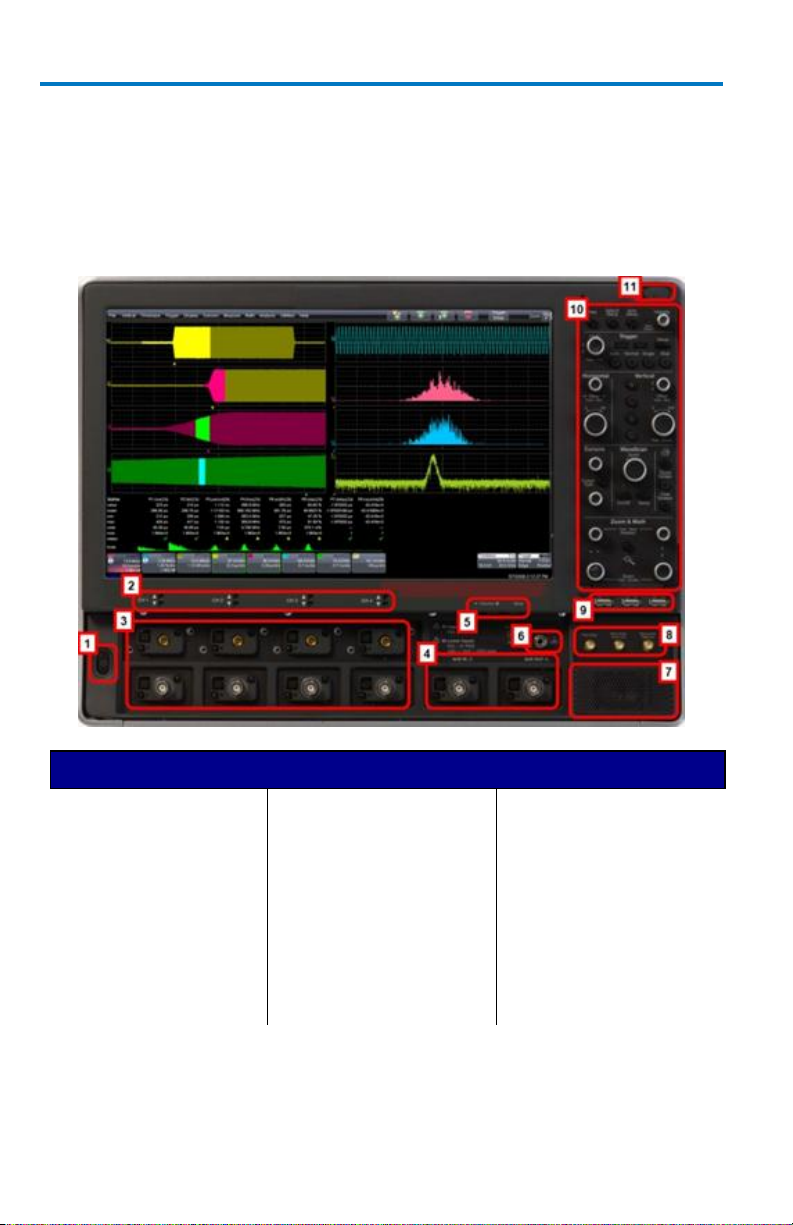
16
922157-00 Rev A
Number and Description
1. Power Button
2. Channel Row LED
Indicator
3. Channel Inputs
4. Auxiliary Input and
Output
5. Volume Control and
Mute Button
6. Ground Connector
7. Speaker
8. Fast Edge, Recovered
Clock, and Data
Outputs
9. USB Ports
10. Detachable Front
Panel Control
11. Front Panel Control
Release Switch
Front of 9xxMZi-A Master Acquisition Module
The 9xxMZi-A Master Acquisition Module includes Controls, Display,
ChannelSync Clock Architecture, and a single, internal acquisition system.
The CPU is contained in the separate, physical CPU Module, but is included
with the LabMaster 9xxMZi-A. Additional acquisition capability is
contained in separate Slave Acquisition Modules.
Page 25
Getting Started Manual
922157-00 Rev A
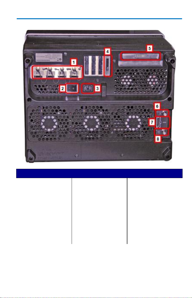
17
Number and Description
1. Channel Sync Outputs
- SMA 10 GHz Clock
and PCIe 1 Lane
Control Connections
(for corresponding
Slave Acquisition
Modules)
2. Power Switch
3. AC Power Plug
4. PCIe 1 Lane DATA
Output (to CPU
Module)
5. DVI-D Video Input (for
DVI-D Output Signal
from CPU)
6. 10 MHz Reference
Clock Input
(Grounded EMI Shield
required when port is
not in use)
7. LBUS Output
8. 10 MHz Reference
Clock Output
Back of 9xxMZi-A Master Acquisition Module
Page 26
LabMaster 9 Zi-A
18
922157-00 Rev A
PLEASE NOTE THE FOLLOWING:
Cap off unused ChannelSync SMA sockets (item 1) using the provided
chain-linked 50 Ω terminations.
VGA/WXGA Video Input connectors (item 5) must be connected with
the supplied 1 meter cable to the VGA/WXGA Video Output on the
CPU Module for your touch-screen display to function.
10 MHz Reference Clock Inputs are specifically intended for
synchronization with other instruments; not between Master and Slave
modules.
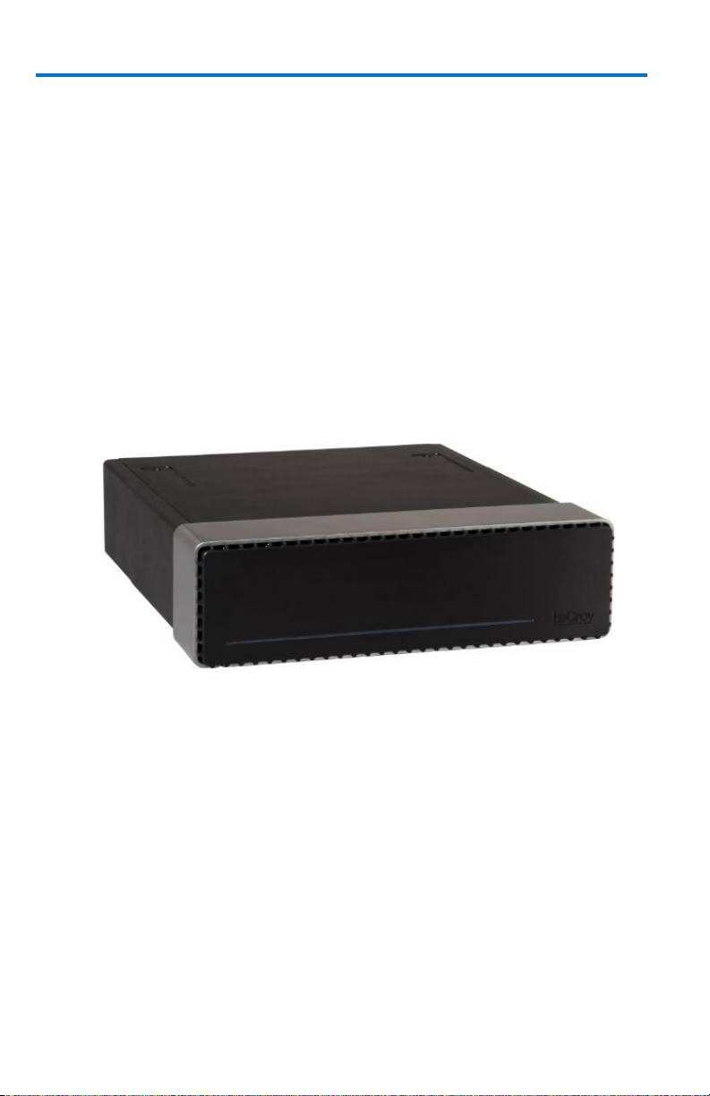
Front of CPU Module
In the Master Acquisition Module configuration, the 9xxMZi-A Master
Acquisition Module connects to a separate CPU Module, shown below.
Page 27
Getting Started Manual
922157-00 Rev A
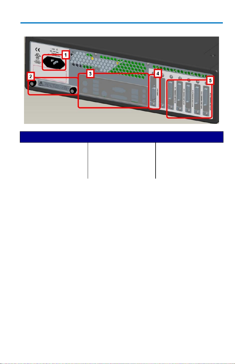
19
Number and Description
1. AC Power Plug
2. Removable Hard Drive
3. The I/O Panel
4. DVI-D Video Output
5. PCIe 4 Lane Data
Inputs (from
corresponding Slave
Acquisition Modules).
Back of CPU Module
PLEASE NOTE THE FOLLOWING:
The PCIe 4 Lane Data Inputs (item 5) also accommodate PCIe Expansion
Slot options for GPIB and LSIB. Option cards must be specified when
ordering and installed at the Teledyne LeCroy factory into any number of
the same five slots used for the Acquisition Modules. The slot between
the DVI-D Video Output connector and the PCIe 4 Lane Data Connection
for Channels 1-4 is unavailable.
The DVI-D Video Output connector (item 4) must be connected to the
DVI-D Video Input on the back of the 9xxMZi-A Master Acquisition Module
with the supplied 1 meter cable for your touch-screen display to function.
Page 28
LabMaster 9 Zi-A
20
922157-00 Rev A
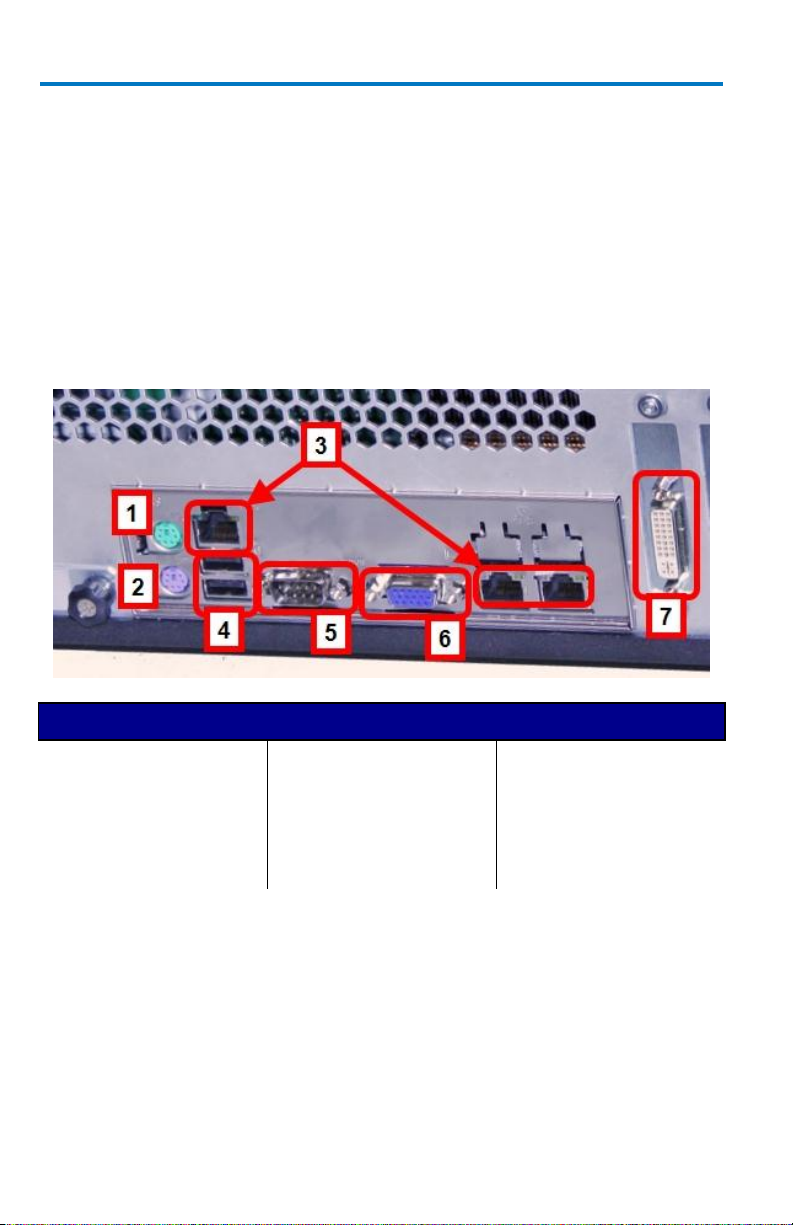
Number and Description
1. Mouse
2. Keyboard
3. Ethernet Ports
4. USB Ports
5. 15-pin VGA/WXGA
Video Input
6. 15-pin VGA/WXGA
Video Output
7. DVI-D Video Output
Input/Output Panel
9CZi-A Master Control Module and
9xxMZi-AMaster Acquisition Module
The available connections are the same, only the location differs:
I/O panel is on the back of the 9CZi-A Master Control Module unit
(on page 14).
I/O panel is on the back of the CPU Module (on page 17)
corresponding to 9xxMZi-A Master Acquisition Module.
Page 29
Getting Started Manual
922157-00 Rev A
21
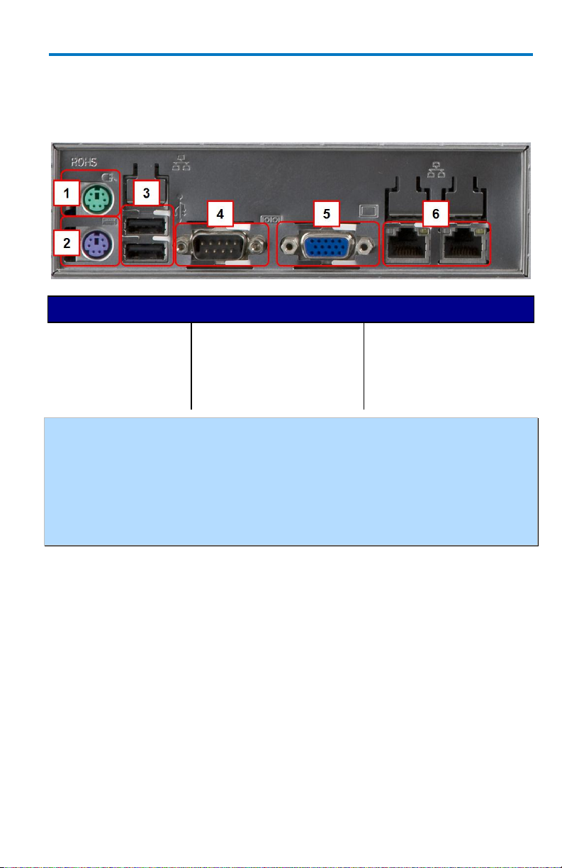
Number and Description
1. Mouse
2. Keyboard
3. Host USB Ports
4. 9-pin Serial Port
(disabled)
5. 15-pin Video Output
(disabled)
6. Ethernet ports (LAN)
MCM-Zi Master Control Module
The I/O panel is located on the back of the MCM-Zi Master Control Module
(page 12).
NOTE: The MCM-Zi motherboard is a server-class motherboard with certain I/O
capabilities (serial port, VGA/WXGA video output) that are not utilized by the
MCM-Zi, even though the physical connectors remain on the I/O panel. The 9-pin
serial port is used for communication to the server motherboard, and the 15-pin
video connector only outputs text debug messages from the motherboard. Since
these capabilities are not useful for the MCM-Zi, they are disabled in the BIOS and
will not provide any I/O should you connect to them.
Page 30
LabMaster 9 Zi-A
22
922157-00 Rev A
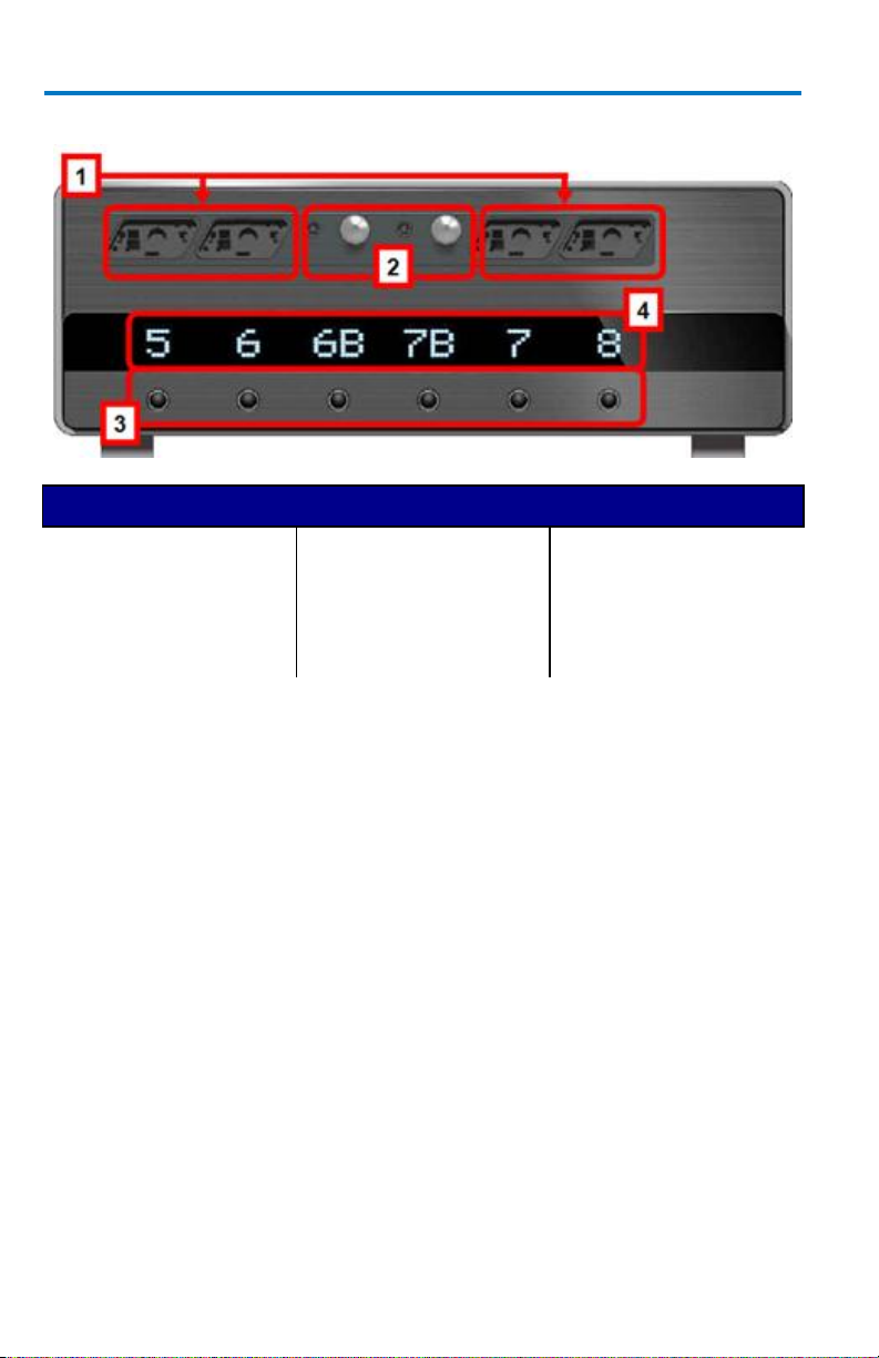
Number and Description
1. ProLink Compatible
Inputs
2. 2.4/2.92 mm
Compatible Inputs (on
>20 GHz Model Slave
Acquisition Modules
Only)
3. Channel ON/OFF
Buttons
4. Corresponding
Channel Number
Indicators
Front of 9xxSZi-A Slave Acquisition Module
PLEASE NOTE THE FOLLOWING:
If your LabMaster system runs multiple Slave Acquisition Modules, for
optimal channel access and convenience, we recommend stacking the
modules on top of each other on your bench, inside Teledyne LeCroy's
available cart, or inside of your own rack (modules must be specifically
ordered for rack mounting from the Teledyne LeCroy factory).
The 9xxSZi-A Slave Acquisition Modules are available in a variety of
bandwidths and channel density configurations. Each example shown
previously contains a mix of 20 GHz and >20 GHz Slave Acquisition
Modules. Each Slave Acquisition Module is compatible with either Master
Module (Control or Acquisition). Refer to specifications on the datasheet
maintained at teledynelecroy.com.
Page 31

Getting Started Manual
922157-00 Rev A
23
Number and Description
1. ChannelSync PCIe 1
Lane Control Input
2. PCIe 4 Lane Data
Output
3. ChannelSync SMA 10
GHz Clock Input
4. AUX IN rated for 50 Ω
input
5. AC Power Plug
Back of 9xxSZi-A Slave Acquisition Module
PLEASE NOTE THE FOLLOWING:
Only the back of the 9CZi-A Master Control Module or the back of the
9xxMZi-A Master Acquisition Module has 10 MHz Reference Clock
Input/Output connections.
10 MHz Reference Clock Inputs are specifically intended for
synchronization with other instruments; not between Master and Slave
modules.
Page 32

LabMaster 9 Zi-A
24
922157-00 Rev A
ChannelSync Mainframe Hub
The CMH-20 ChannelSync Mainframe Hub provides a simple and effective
means to expand a LabMaster system beyond 20 channels (5 Acquisition
Modules). This is accomplished without any degradation of the timing
accuracy specifications. The Mainframe Hub is populated with cards for
each acquisition module (the back panel of the CMH-20 shown below is
populated with 20 cards for use with 20 Acquisition Modules, or 80 total
channels).
Connect a PCIe 1 Lane cable from the MCM-Zi Channel 1-4 output to the
single PCIe 1 Lane input at the lower right of the CMH-20 back panel.
Connect four PCl4 4 Lane cables from the MCM-Zi data outputs for
channels 1-4, 5-8, 9-12, and 13-16 to the four PCIe 4 Lane data inputs along
the bottom of the CMH-20 back panel (to the left of the PCLe 1 input).
Connect from the PCIe 1 Lane Control, PCIe 4 Lane Data, and 10 GHz
ChannelSync Clock outputs to the corresponding inputs on the Acquisition
Modules.
Page 33

Getting Started Manual
922157-00 Rev A
25
LabMaster Hardware Set Up
Overview
These instructions explain the setup of your LabMaster modules for both
Master Control Module or Master Acquisition Module configurations. As
mentioned previously in LabMaster Hardware Overview (on page 2),
LabMaster modules are designed to work with one another for a variety of
extensible configurations and customized solution possibilities; however,
they are purchased as either Master Control Module or Master Acquisition
Module configurations.
LabMaster Setup Styles
As mentioned previously, LabMaster modules are designed to work with
one another for a variety of extensible configurations and customized
solution possibilities. They are purchased as Master Control Module or
Master Acquisition Module configurations. You can choose your own
LabMaster Setup Style - meaning, you can decide to Stack your LabMaster
modules or Rack them inside an available Cart complete with lockable front
wheels.
NOTE: If your LabMaster system runs multiple Slave Acquisition Modules, for
optimal channel access and convenience, Teledyne LeCroy recommends stacking
the modules on top of each other on your bench, inside Teledyne LeCroy's
available Cart or inside of your own rack (modules must be specifically ordered for
rack mounting from the Teledyne LeCroy factory).
Page 34

LabMaster 9 Zi-A
26
922157-00 Rev A
LabMaster Master Control Module and Master Acquisition Module stack setups
LabMaster set up inside the available cart
Page 35

Getting Started Manual
922157-00 Rev A
27
9CZi-A Master Control Module Configuration
This LabMaster configuration involves making PCIe 1 and 4 Lane, DVI-D,
SMA 72", and Power Cable connections. Follow these steps to properly
connect all parts of your LabMaster setup.
PCIe 1 Lane Cable - Master Control Module to Slave
Acquisition Module SYNC Connection(s)
Connect each PCIe 1 Lane Control Output on the back of your 9CZi-A
Master Control Module to the PCIe 1 Lane Input on each 9xxSZi-A Slave
Acquisition Module used in your system using the PCIe 1 Lane cable(s)
provided.
On the back of the Master Control Module, plug one end of the PCIe 1
Lane cable into the PCIe 1 Lane Channel Sync Output (labeled SYNC).
Page 36

LabMaster 9 Zi-A
28
922157-00 Rev A
Now, on the back of the Slave Acquisition Module, connect the other end
of the same PCIe 1 Lane cable into the corresponding PCIe 1 Lane Channel
Sync Input (labeled SYNC).
Gently pull the green tab on the cable plug to remove it.
Repeat the previous steps for every additional Slave Acquisition Module in
your system.
Page 37

Getting Started Manual
922157-00 Rev A
29
PLEASE NOTE THE FOLLOWING:
PCIe 1 Lane Cable plugs are keyed with a single groove along one wide
side of the plug. The plug must be inserted into the socket with the
groove aligned properly.
Connect into your Slave Acquisition Modules from the correct channel
groupings on the 9CZi-A Master Control Module; meaning, your first Slave
Acquisition Module is connected from the CHANNEL 1-4 output, second
from the CHANNEL 5-9 output, third from the CHANNEL 9-12 output,
fourth from the CHANNEL 13-16 output, and last from the CHANNEL 1720 output.
If you are connecting less than 5 of the Slave Acquisition Modules, the
PCIe 1 Lane Channel Sync Outputs on the back of the Master Control
Module may not be skipped and must be connected in consecutive order
into the PCIe 1 Lane Channel Sync Inputs on the back of the corresponding
slaves.
PCIe 4 Lane Cable - Slave Acquisition Module to Master
Control Module SYNC Connection(s)
Now, let's continue making the PCI Express connections by cabling the PCIe
4 Lane Data Output on the back of each 9xxSZi-ASlave Acquisition Module
to the PCIe 4 Lane Data Inputs on the back of your 9CZi-AMaster Control
Module using PCIe 4 Lane cable(s) provided.
Page 38

LabMaster 9 Zi-A
30
922157-00 Rev A
On the back of a Slave Acquisition Module, connect one end of a PCIe 4
Lane cable from the PCIe 4 Lane Data Output (labeled DATALINK).
Now, on the back of the Master Control Module, connect the other end of
the same PCIe 4 Lane cable into the corresponding PCIe 4 Lane Data Input
(labeled DATALINK CHANNEL).
Page 39

Getting Started Manual
922157-00 Rev A
31
Gently pull the green tab on the cable plug to remove it.
Repeat the previous steps for every additional Slave Acquisition Module in
your system.
PLEASE NOTE THE FOLLOWING:
PCIe 4 Lane Cable plugs are keyed with a single groove along one wide
side of the plug. The plug must be inserted into the socket with the
groove aligned properly.
Be sure to connect from your Slave Acquisition Modules into the correct
channel groupings on the 9CZi-A Master Control Module; meaning, your
first Slave Acquisition Module is connected into DATALINK CHANNEL 1-4
input on the Master Control Module, second into the DATALINK CHANNEL
5-9 input, third into the DATALINK CHANNEL 9-12 input, fourth into the
DATALINK CHANNEL 13-16 input, and last into the DATALINK CHANNEL
17-20 input.
If you are connecting less than 5 of the Slave Acquisition Modules, the
PCIe 4 Lane Data Inputs on the back of the Master Control Modulemay
not be skipped and must be connected in consecutive order from the PCIe
4 Lane Data Outputs on the back of the corresponding slaves.
Page 40

LabMaster 9 Zi-A
32
922157-00 Rev A
DVI-D Connection - Video Card to Touch-Screen Display on
the Master Control Module
The DVI-D Video Output must be connected to the DVI-D Video Input
(both on the back of the Master Control Module) using the provided DVI-D
cable for the touch-screen display to function.
Connect one end of the provided DVI-D cable into the DVI-D Video Output
on the back of the Master Control Module.
Now, connect the other end of the same DVI-D cable into the DVI-D Video
Input, also on the back of the Master Control Module.
Page 41

Getting Started Manual
922157-00 Rev A
33
NOTE: The connections are specifically DVI-D.
SMA 72" Cables - Master Control Module to Slave
Acquisition Module Connection(s) for Reference Clock
Connect each SMA 10 GHz Clock Output on the back of your 9CZi-A Master
Control Module to the SMA 10 GHz Clock Input on each 9xxSZi-A Slave
Acquisition Module used in your system using the SMA 72" cable(s)
provided.
NOTE: Use an SMA torque wrench and ensure connections are properly tightened.
Page 42

LabMaster 9 Zi-A
34
922157-00 Rev A
On the back of the Master Control Module, connect one end of an
SMA 72" cable from a SMA 10 GHz Clock Output (labeled REF, unscrew the
chain-linked 50 Ω termination, if necessary).
Now, on the back of the Slave Acquisition Module, connect the other end
of the same SMA 72" cable into the corresponding SMA 10 GHz Clock Input
(labeled REF).
Repeat the previous steps for every additional Slave Acquisition Module
in your system.
Page 43

Getting Started Manual
922157-00 Rev A
35
Cap off any unused SMA 10 GHz Clock Outputs on the back of your 9CZi-A
Master Control Module using the chain-linked 50 Ω terminations provided.
Power Cable Connections and Main Power Switch
The combined draw from your 9CZi-A Master Control Module and 9xxSZi-A
Slave Acquisition Modules (max of 5) approximately totals 5 kW, Teledyne
LeCroy advises that your power connections be generally divided as
follows:
The Master Control Module requires less power and may be
combined with a Slave Acquisition Module to a different circuit
rated to handle a combined 2050 Watts.
Connect any additional pairs of Slave Acquisition Modules to a
different circuit rated to handle a combined 2050 Watts.
A 15A/250V 14AWG rated grounded cord set with a IEC320 right-angle
Type C15 connector with a slotted groove is provided specifically for the
Master Control Module. Components other than the Master Control
Module are each provided with a standard 10A/250V 18AWG rated
grounded cord set with an IEC320 right-angle Type C13 connector. Ω
NOTE: Always refer to the product datasheet specifications at teledynelecroy.com
for the most current and detailed power ratings.
Page 44

LabMaster 9 Zi-A
36
922157-00 Rev A
When all connections are made, the main switch on the front of the Master
Control Module powers all connected items - Master and Slave Acquisition
Module(s) - as a single LabMaster unit.
NOTE: If any connections are incorrect, the main power switch does not power on
your system.
Page 45

Getting Started Manual
922157-00 Rev A
37
Page 46

LabMaster 9 Zi-A
38
922157-00 Rev A
MCM-Zi Master Control Module Configuration
This LabMaster configuration involves making PCIe 1 and 4 Lane, SMA 72",
and Power Cables. Follow these steps to properly connect all parts of your
LabMaster.
PCIe 1 Lane Cable SYNC Connection(s)
Connect each PCIe 1 Lane Control Input on the back of your 10-xxZi
Acquisition Modules to a PCIe 1 Lane Output on the MCM-Zi Master
Control Module using the PCIe 1 Lane cable(s) provided.
On the back of the Master Control Module, plug one end of the PCIe 1 Lane
cable into the PCIe 1 Lane Channel Sync Output (labeled SYNC).
Page 47

Getting Started Manual
922157-00 Rev A
39
Now, connect the other end of the 1 Lane cable into the SYNC socket on
the back of the Acquisition Module.
Gently pull the green tab on the cable plug to remove it.
Repeat these steps for every additional Acquisition Module in your system.
Page 48

LabMaster 9 Zi-A
40
922157-00 Rev A
PLEASE NOTE THE FOLLOWING:
PCIe 1 Lane Cable plugs are keyed with a single groove along one wide
side of the plug. The plug must be inserted into the socket with the
groove aligned properly.
Connect into your Acquisition Modules from the correct channel
groupings on the Master Control Module; meaning, your first Acquisition
Module is connected from the CHANNEL 1-4 output, second from the
CHANNEL 5-8 output, third from the CHANNEL 9-12 output, etc.
If you are connecting less than 5 of the Acquisition Modules, the PCIe 1
Lane Channel Sync Outputs on the back of the Master Control Module
may not be skipped and must be connected in consecutive order into the
PCIe 1 Lane Channel Sync Inputs on the back of the corresponding
acquisition modules.
PCIe 4 Lane DATALINK Connection(s)
Continue making the PCI Express connections by cabling the PCIe 4 Lane
Data Output on the back of each 10-xxZi Acquisition Module to the PCIe 4
Lane Data Inputs on the back of your MCM-Zi Master Control Module using
PCIe 4 Lane cable(s) provided.
Page 49

Getting Started Manual
922157-00 Rev A
41
On the back of the Acquisition Module, connect one end of a PCIe 4 lane
cable from the PCIe 4 Lane Data Output (labeled DATALINK).
Now, on the back of the Master Control Module, connect the other end of
the same PCIe 4 Lane cable into the corresponding PCIe 4 Lane Data Input
(labeled DATALINK CHANNEL).
Page 50

LabMaster 9 Zi-A
42
922157-00 Rev A
Gently pull the green tab on the cable plug to remove it.
Repeat the previous steps for every additional Acquisition Module in your
system.
PLEASE NOTE THE FOLLOWING:
PCIe 4 Lane Cable plugs are keyed with a single groove along one wide
side of the plug. The plug must be inserted into the socket with the
groove aligned properly.
Be sure to connect your Acquisition Modules to the correct channel
groupings on the Master Control Module; First Acquisition Module is
connected into DATALINK CHANNEL 1-4, second into the DATALINK
CHANNEL 5-9 input, third into the DATALINK CHANNEL 9-12 input,
fourth into the DATALINK CHANNEL 13-16 input, and last into the
DATALINK CHANNEL 17-20 input.
If you are connecting less than 5 of the Slave Acquisition Modules, the
PCIe 4 Lane Data Inputs on the back of the Master Control Module may
not be skipped and must be connected in consecutive order from the PCIe
4 Lane Data Outputs on the back of the corresponding slaves.
Page 51

Getting Started Manual
922157-00 Rev A
43
SMA 72" Cables - ChannelSync Clock Connections
Connect each SMA 10 GHz Clock Output on the back of your MCM-Zi
Master Control Module to the SMA 10 GHz Clock Input on each 10-xxZi
Acquisition Module used in your system using the SMA 72" Male to Male
cable(s) provided.
NOTE: Use an SMA torque wrench and ensure connections are properly tightened.
On the back of the Master Control Module, connect one end of an SMA 72"
cable from a SMA 10 GHz Clock Output (labeled REF, unscrew the chain-
linked 50 Ω termination, if necessary).
Page 52

LabMaster 9 Zi-A
44
922157-00 Rev A
Now, on the back of the Acquisition Module, connect the other end of the
same SMA 72" cable into the corresponding SMA 10 GHz Clock Input
(labeled REF).
Repeat the previous steps for every additional Acquisition Module in your
system.
Cap off unused SMA 10 GHz Clock Outputs on the back of your Master
Control Module using the chain-linked 50 Ω terminations provided.
Page 53

Getting Started Manual
922157-00 Rev A
45
Power Cable Connections and Main Power Switch
Teledyne LeCroy advises that you note the power ratings of the individual
modules and connect them to suitably rated circuits.
MCM-Zi Control Module comes with an IEC60320 Type C13 power
inlet connector.
9xxSZi-A Acquisition Module comes with an IEC60320 Type C20
power inlet connector.
Always refer to the product datasheet at www.teledynelecroy.com for the
most current and detailed specifications regarding power ratings.
CAUTION: The combined draw from your Master Control Module and
Acquisition Modules (max of 20) can be many kilowatts. Two acquisition
modules connected to a single circuit may cause an overcurrent condition for that
circuit.
When all connections are made, the main power switch on the front of the
Master Control Module powers on all components as a single unit.
NOTE: If any connections are incorrect, the main power switch will not power on
the system.
Page 54

LabMaster 9 Zi-A
46
922157-00 Rev A
9xxMZi-A Master Acquisition Module Configuration
PCIe 1 Lane Cable - Master Acquisition Module to Slave
Acquisition Module
Connect each PCIe 1 Lane Control Output on the back of your 9xxMZi-A
Master Acquisition Module to the PCIe 1 Lane Input on each 9xxSZi-A
Slave Acquisition Module used in your system using the PCIe 1 Lane
cable(s) provided.
On the back of the Master Acquisition Module, plug one end of the PCIe 1
Lane cable into the PCIe 1 Lane Channel Sync Output (labeled SYNC).
Now, connect the other end of the 1 Lane cable into the SYNC socket on
the back of the 9 SZi-A (Slave).
Page 55

Getting Started Manual
922157-00 Rev A
47
Gently pull the green tab on the cable plug to remove it.
Repeat the previous steps for every additional Slave Acquisition Module in
your system.
PLEASE NOTE THE FOLLOWING:
PCIe 1 Lane Cable plugs are keyed with a single groove along one wide
Connect into your Slave Acquisition Modules from the correct channel
If you are connecting less than 4 of the Slave Acquisition Modules, the
side of the plug. The plug must be inserted into the socket with the
groove aligned properly.
groupings on the 9xxMZi-A Master Acquisition Module; meaning, your
first Slave Acquisition Module is connected from the CHANNEL 5-9 output,
second from the CHANNEL 9-12 output, third from the CHANNEL 13-16
output, and last from the CHANNEL 17-20 output.
PCIe 1 Lane Channel Sync Outputs on the back of the Master Acquisition
Module may not be skipped and must be connected in consecutive order
into the PCIe 1 Lane Channel Sync Inputs on the back of the corresponding
slaves.
Page 56

LabMaster 9 Zi-A
48
922157-00 Rev A
PCIe 4 Lane Cable - CPU Module to Master Acquisition
Module
Make a connection for Channels 1-4 from the back of the Master
Acquisition Module into the PCIe 4 Lane Data Input (labeled
DATALINK CHANNEL 1-4) on the back of the CPU Module.
Connect one end of a PCIe 4 Lane cable to the PCIe 4 Lane Data Output
(labeled DATALINK CHANNEL 1-4) on the back of the Master Acquisition
Module.
Page 57

Getting Started Manual
922157-00 Rev A
49
Now, on the back of the CPU Module, connect the other end of the same
PCIe 4 Lane cable specifically into the PCIe 4 Lane Data Input (labeled
DATALINK CHANNEL 1-4).
9xxSZi-ASlave Acquisition Modules connections for channels above 1-4,
connections are made from the PCIe 4 Lane Data Output (labeled
DATALINK CHANNEL) on the back of each Slave Acquisition Module into
the corresponding PCIe 4 Lane Data Input (labeled DATALINK CHANNEL)
on the back of the CPU Module.
Gently pull the green tab on the cable plug to remove it.
Page 58

LabMaster 9 Zi-A
50
922157-00 Rev A
PLEASE NOTE THE FOLLOWING:
PCIe 4 Lane Cable plugs are keyed with a single groove along one wide
side of the plug. The plug must be inserted into the socket with the
groove aligned properly.
If you are connecting less than 4 of the Slave Acquisition Modules, the
PCIe 4 Lane Data Inputs on the back of the CPU Modulemay not be
skipped and must be connected in consecutive order from the PCIe 4 Lane
Data Outputs on the back of the corresponding slaves.
PCIe 4 Lane Cable - Slave Acquisition Module to CPU
Module
Continue making the PCI Express connections for channels above 1-4, by
cabling the PCIe 4 Lane Data Output on the back of each 9xxSZi-ASlave
Acquisition Module to the PCIe 4 Lane Data Inputs on the back of your
CPU Module using PCIe 4 Lane cable(s) provided.
Page 59

Getting Started Manual
922157-00 Rev A
51
Plug one end of a PCIe 4 Lane cable into the PCIe 4 Lane Data Output
(labeled DATALINK) on the back of each Slave Acquisition Module.
Now, on the back of the CPU Module, connect the other end of the same
PCIe 4 Lane cable into the corresponding PCIe 4 Lane Data Input (labeled
DATALINK CHANNEL).
Page 60

LabMaster 9 Zi-A
52
922157-00 Rev A
Gently pull the green tab on the cable plug to remove it.
PLEASE NOTE THE FOLLOWING:
PCIe 4 Lane Cable plugs are keyed with a single groove along one wide
side of the plug. The plug must be inserted into the socket with the
groove aligned properly.
If you are connecting less than four of the Slave Acquisition Modules, the
PCIe 4 Lane Data Inputs on the back of the CPU Modulemay not be
skipped and must be connected in consecutive order from the PCIe 4 Lane
Data Outputs on the back of the corresponding slaves.
Page 61

Getting Started Manual
922157-00 Rev A
53
DVI-D Connection - CPU Module's Video Card Output to the
Master Acquisition Module's Touch-Screen Display Video
Input
Connect the CPU Module's Video Card DVI-D Output into the Master
Acquisition Module's Touch-Screen Display DVI-D Input using the DVI-D
cable provided.
Connect one end of the provided DVI-D cable into the DVI-D Video Output
on the back of the CPU Module.
Page 62

LabMaster 9 Zi-A
54
922157-00 Rev A
Now, connect the other end of the same DVI-D cable into the DVI-D Video
Input on the back of the Master Acquisition Module.
NOTE: The connections are specifically DVI-D.
Page 63

Getting Started Manual
922157-00 Rev A
55
SMA 72" Cables - Master Acquisition Module to Slave
Acquisition Module Reference Clock Connection
Connect each SMA 10 GHz Clock Output on the back of your 9xxMZi-A
Master Acquisition Module to the SMA 10 GHz Clock Input on each
9xxSZi-A Slave Acquisition Module used in your system using the SMA 72"
cable(s) provided.
NOTE: Use an SMA torque wrench and ensure connections are properly tightened.
On the back of the Master Acquisition Module, connect one end of an
SMA 72" cable from a SMA 10 GHz Clock Output (labeled REF, unscrew the
chain-linked 50 Ω termination, if necessary).
SMA 72" M to M Cable
Page 64

LabMaster 9 Zi-A
56
922157-00 Rev A
Now, on the back of the Slave Acquisition Module, connect the other end
of the same SMA 72" cable into the corresponding SMA 10 GHz Clock Input
(labeled REF).
Repeat the previous steps for every additional Slave Acquisition Module in
your system.
Cap off any unused SMA 10 GHz Clock Outputs on the back of your 9xxMZiA Master Acquisition Module using the chain-linked 50 Ω terminations
provided.
Page 65

Getting Started Manual
922157-00 Rev A
57
Power Cable Connection and Main Power Switch
The combined draw from your 9xxMZi-AMaster Acquisition Module,
9xxSZi-ASlave Acquisition Modules (max of 4), and CPU Module
approximately totals 5 kW, Teledyne LeCroy advises that your power
connections be generally divided as follows:
Connect the Master Acquisition Module and its CPU Module to a
single circuit rated to handle a combined 1250 Watts.
Connect any additional pairs of Slave Acquisition Modules to a
different circuit rated to handle a combined 2050 Watts.
NOTE: Always refer to the product datasheet specifications at teledynelecroy.com
for the most current and detailed power ratings.
15A/250V 14AWG rated grounded cord set with a IEC320 right-angle Type
C15 connector with a slotted groove is provided specifically for the Master
Acquisition Module. Components other than the Master Acquisition
Module are each provided with a standard 10A/250V 18AWG rated
grounded cord set with an IEC320 right-angle Type C13 connector.
Page 66

LabMaster 9 Zi-A
58
922157-00 Rev A
When all connections are made, the Standby Power switch on the front of
the Master Acquisition Module powers all connected items (Master
Acquisition, Slave Acquisition, and CPU Module) as a single LabMaster unit.
NOTE: If any connections are incorrect, the main power switch does not power on
your system.
Page 67

Getting Started Manual
922157-00 Rev A
59
Removing and Attaching the Front Panel Control
Detach the Front Panel Control from the oscilloscope by sliding the
detachment lever to the left and pulling at the right.
Attach the front panel by inserting the lower part first, sliding the
detachment lever to the left, and then pushing the top in place.
Page 68

LabMaster 9 Zi-A
60
922157-00 Rev A
FRONT PANEL AS A REMOTE CONTROL
While detached, your front panel (standard or 4 channel version) can be
used as a remote control. Just plug-and-play connect to the oscilloscope
using the USB - A to USB - Mini B cable provided.
NOTE: While a standard front panel comes with your Zi oscilloscope, Teledyne
LeCroy offers additional standard front panels or a 4 channel version (as follows) to
better suit the way you work.
Page 69

Getting Started Manual
922157-00 Rev A
61
Touch Screen and External Displays
Set Up Internal Display
Connect the DVI-D Video Output on the CPU to the DVI-D Video Input on
the 9xxMZi-A Master Acquisition Module to enable the internal, built-in
touch-screen display. The 9CZi-A Master Control Module has the same
display capabilities as the 9xxMZi-A Master Acquisition Module, except
there is no separate CPU module. Instead, a short "jumper" cable connects
video output to input. The MCM-Zi Master Control Module does not
require any internal display set up.
Set Up External Display
You may operate the instrument using the built-in touch-screen or attach
an external monitor for extended display. A properly configured external
display will take on all the touch-screen capabilities of the internal display.
NOTE: LabMaster 9xxMZi-A and 9CZi-A do not support extended desktop mode
when connected to an external monitor. LabMaster MCM-Zi does support
extended desktop mode. If the external monitor uses a Fujitsu touch screen driver,
it will not work as a touch screen but will support extended display.
To connect to an external monitor:
1. Choose File > Exit to close the oscilloscope application so that the
2. Connect the oscilloscope to the external monitor from the DVI-D
3. Right-click on the desktop to display the settings menu, then
4. On the Windows display dialog:
Windows desktop is visible (you do not need to shut down
completely).
video output connector.
choose Screen Resolution.
Select display number 2 (the external monitor) and choose
Multiple displays: Extend this display.
Drag the display number 2 icon to its location in your setup
(above or below the oscilloscope display).
Make any other desired display selections, then touch
Apply and OK.
Page 70

LabMaster 9 Zi-A
62
922157-00 Rev A
5. Use the Start DSO desktop icon to restart the oscilloscope
application.
6. Choose Display > Display Setup.
7. On the Display setup dialog, check Extend Grids on 2
The total number of grids is now distributed over both displays.
nd
Monitor.
Both displays before Dual Display Mode selection. In this example, the top monitor
is the external display.
Page 71

Getting Started Manual
922157-00 Rev A
63
Grids distributed after Dual Display Mode selection. Trace descriptor boxes move
with the trace (note the movement of C1-C4). Other controls remain on the primary
display (Display 1, which in this example is the bottom, internal display).
Page 72

LabMaster 9 Zi-A
64
922157-00 Rev A
Signal Inputs
Interfaces
LabMaster 9 Zi systems are equipped with a variety of interfaces to allow
you to connect cables directly to the oscilloscope channels, reducing the
need to use costly adapters that may be easily lost or misplaced.
The interfaces power the probe and completely integrate the probe with
the oscilloscope channel in a number of ways:
Upon connection, the probe is recognized and some setup
information, such as input coupling and attenuation, is performed
automatically.
System (probe plus oscilloscope) gain settings are automatically
calculated and displayed based on the probe attenuation.
Most active probes match probe to oscilloscope response
automatically using probe response data stored in an on-board
EEPROM. This ensures the best possible combined probe plus
oscilloscope channel frequency response without the need to
perform any de-embedding procedure.
Interfaces differ in bandwidth capabilities, so the interfaces contained on
your oscilloscope—and their exact location—depend on the bandwidth
rating of the oscilloscope model you purchased.
High-bandwidth interfaces (45 GHz and up) must be enabled by selecting
the appropriate Dual Bandwidth Interleave setting on the Timebase dialog
and the Input B setting on the Channel dialog.
NOTE: AUX INPUT and AUX OUTPUT connections are typically located on the Front
of the oscilloscope near the other interfaces.
ProLink Interface
All LabMaster 9xxMZi-A Master Acquisition Modules and 9xxSZi-A Slave
Acquisition Modules use the ProLink interface for inputs up to 20 GHz on
channels 1-4.
The ProLink interface contains a 6-pin power and communication
connection and a Blind Mate Adapter (BMA) signal connection to the
probe. It offers 50 Ω input impedance and provides probe power and
Page 73

Getting Started Manual
922157-00 Rev A
65
control for a wide range of probes with bandwidth ratings from 3 GHz to 20
GHz. The nature of the ProLink interface with its recessed BMA connector
means that an adapter must be connected to the ProLink interface to allow
SMA or 2.92/K connector terminated cables to be attached to the
oscilloscope channel. These adapters are normally provided with your
oscilloscope, and are described in ProLink Interface Adapters (on page 67).
ProBus Interface
LabMaster 9xxMZi-A Master Acquisition Modules rated to 20 GHz use the
ProBus interface for inputs up to 25 GHz on channels 1-4.
LabMaster 945MZi-A Master Acquisition Modules use the ProBus interface
for inputs up to 25 GHz on channels 1 and 4, input B.
The ProBus interface contains a 6-pin power and communication
connection and a BNC signal connection to the probe. It offers both 50 Ω/1
MΩ input impedance and provides probe power and control for a wide
range of probes such as high impedance passive probes, high impedance
active probes, current probes, high voltage probes, and differential probes.
ProBus also includes sense rings for detecting passive probes. The ProBus
interface may also have a BNC-terminated cable connected directly to it.
ProBus is based on a BNC connector and, depending on the exact BNC
connector used and the oscilloscope design, is rated for up to 4 GHz with
50 Ω coupling or up to 1 GHz for 1 MΩ coupling (depending on the exact
model purchase).
2.92 mm Interface
LabMaster 930SZi-A Slave Acquisition Modules use the 2.92 mm interface
for inputs up to 36 GHz on channels 2 and 3, input B.
LabMaster 945MZi-A Master Acquisition Modules and 945SZi-A Slave
Acquisition Modules use the 2.92 mm interface for inputs up to 36 GHz on
channel 2, input B.
This interface consists of a precision connector and a LEMO power and
communication connector. It offers 50 Ω input impedance only.
The 2.92 mm high-bandwidth electrical paths are comprised of two
connector halves/subassemblies which have a common mating interface:
The first connector half is mounted onto the oscilloscope
connector panel. The outer end of this connector has a
Page 74

LabMaster 9 Zi-A
66
922157-00 Rev A
combination of grooves, external threads and a coaxial interface
with a 2.92 mm airline geometry.
The second connector half is the connector saver. It has a similar
interface on one end, with spring-biased inner and outer contacts.
The connector saver has projections which interlock with slots on the
mounted connector and a coupling nut which secures the two halves;
resulting in a non-rotational, torque independent electrical connection. The
spring-biased inner and outer contacts eliminate the need for specifying
proof torque and no tools are required to mate or un-mate the connection.
The connector saver is easily field replaceable, should damage occur,
making it a more field reliable system. The 2.92 mm connector savers
operate mode free well beyond 36 GHz.
2.4 mm Interface
LabMaster 945MZi-A Master Acquisition Modules and 945SZi-A Slave
Acquisition Modules use the 2.4 mm interface 25 - 45 GHz inputs on
channel 3, input B. This interface consists of a precision connector and a
LEMO power and communication connector. It offers 50 Ω input
impedance only.
The 2.4 mm high-bandwidth electrical paths are comprised of two
connector halves/subassemblies which have a common mating interface:
The first connector half is mounted onto the oscilloscope
connector panel. The outer end of this connector has a
combination of grooves, external threads and a coaxial interface
with a 2.4 mm airline geometry.
The second connector half is the connector saver. It has a similar
interface on one end, with spring-biased inner and outer contacts.
The connector saver has projections which interlock with slots on the
mounted connector and a coupling nut which secures the two halves;
resulting in a non-rotational, torque independent electrical connection. The
spring-biased inner and outer contacts eliminate the need for specifying
proof torque and no tools are required to mate or un-mate the connection.
The connector saver is easily field replaceable, should damage occur,
making it a more field reliable system. The 2.4 mm connector saver
operates mode free well beyond 45 GHz.
Page 75

Getting Started Manual
922157-00 Rev A
67
NOTE: The mounted connectors for the 2.92 mm and 2.4 mm interfaces look
identical, and the connector savers look very similar, so be sure to attach the
correct connector saver to achieve the desired bandwidth. The 2.92 mm connector
saver will fit over the 2.4 mm mounted connector (and vice versa) but will not yield
the full 45 GHz bandwidth.
ProLink Interface Adapters
Teledyne LeCroy's ProLink Adapters (LPA) provides the ability to connect a
cable to your oscilloscope that is either BNC, SMA, or K (2.92 mm)
terminated. These adapters are only for cable connection since they do not
provide the power and communication interfaces required for probe usage.
In fact, the absence of these connections on the adapters means that a
probe cannot be connected to the oscilloscope when one of these adapters
is connected.
The following cable connections are supported:
BNC, using the LPA-BNC Blind Mate Adapter (BMA) to BNC interface
adapter. This is not normally provide with your oscilloscope, but may
be ordered as an accessory.
SMA , using the LPA-SMA BMA-to-SMA adapter
K-Type (2.92 mm), using the LPA-K BMA-to-2.92 mm adapter (4 are
sent standard in 13 - 45 GHz units).
BMA-to-SMA, BMA-to-BNC, BMA-to-2.92 mm ProLink Adapters.
Page 76

LabMaster 9 Zi-A
68
922157-00 Rev A
First, the BMA Female Connector (1). Then, shown installed are the ProLink
LPA-SMA, LPA-BNC, and LPA-K Adapters (2, 3, and 4).
NOTE: When connecting an active probe to the instrument, an adapter is not
required unless you wish to connect a ProBus compatible probe to a ProLink input.
Connecting the Adapters
The mating end of the ProLink adapter has
four fastening clips (shown right).
When installing an adapter on the
instrument's connector panel, align the
male 6-pin connector with the female
connector and push the adapter straight
forward. You are likely to notice some resistance and hear clicks as the four
clips snap into place. Now, tighten the captive screws.
When removing an adapter, loosen the two captive screws. Push down on
the adapter to unseat the clips. This requires some force and is initially
noisy; however, no damage results to the connector, the floating female
BMA connector, or the pins, as they can accommodate 15 degrees off axis
while mated or unmated.
ProLink Probe Adapters
ProLink Probe Adapters differ from ProLink Interface Adapters in that they
contain a probe power and communication pass-through that the interface
adapters do not have.
Currently, only one probe adapter is available, the LPA-2.92 mm. This
device is used to allow attachment of a probe platform/cable assembly
Page 77

Getting Started Manual
922157-00 Rev A
69
designed for connection to a 2.92 mm Probe Connection Interface to be
connected to a ProLink input connection. For instance, this could be used
to connect a 25 GHz probing system using 2.92 mm and LEMO connections
for connection to a ProLink input.
Connecting the ProLink Probe Adapter is done in a similar way as
connecting a ProLink Interface Adapter.
Probe Dialog
Teledyne LeCroy proprietary probe interfaces provide a complete
measurement solution from probe tip to oscilloscope display. The Probe
Dialog displays probe attenuation and other information, and allows you to
make tip select and other probe settings from the oscilloscope
touchscreen.
The following figure shows a typical channel dialog on a Teledyne LeCroy
oscilloscope containing both ProLink (Input A, Upper) and ProBus (Input B,
Lower) interfaces. The input selection is on the left-hand side of the dialog
box.
When the probe is not connected, there is only a C1 tab selection for
vertical channel setup and the user has the ability to select input coupling
and probe attenuation.
Channel dialog showing Input A's interface controls setup before connection.
Page 78

LabMaster 9 Zi-A
70
922157-00 Rev A
After a probe is connected, it is recognized and an additional tab with the
probe model name is displayed to the right of the C1 tab. Click on the tab
or the probe field to display the probe dialog.
Channel dialog showing Input A's interface controls setup after connection.
This additional tab contains specific information on the connected probe.
Default values for the probes coupling and attenuation are automatically
downloaded from the probe, and these settings along with other attributes
are shown on the dialog.
The probe dialog showing the connected probe's control attributes.
Page 79

Getting Started Manual
922157-00 Rev A
71
Passive Probe Compensation
Passive probes must be compensated to flatten overshoot. This is
accomplished by means of a trimmer at the connector end of the probe.
1. Attach the connector end of your passive probe to any channel.
2. Connect the probe end to the CAL output connector at the front of
the oscilloscope. Ground the probe.
3. Adjust the trim pot at the connector end of the probe until the
square wave is as flat as possible.
Page 80

LabMaster 9 Zi-A
72
922157-00 Rev A
Front Panel
The following Basic Control topics cover the general usage of the hardware
buttons located on the oscilloscope's front panel and the screen control
interface elements of the software.
NOTE: Many specific Front Panel Controls directly correspond with Screen Layout
Controls. For example, the Print front panel button corresponds with the Hardcopy
function at Utilities → Utilities Setup → Hardcopy.
The front panel is divided into sections based on various functions. The
following topics explain these sections in more detail.
Page 81

Getting Started Manual
922157-00 Rev A
73
Miscellaneous Controls and WaveStream Indicator
Help - Press to open the Teledyne LeCroy Online Assistant where
you can click to open the oscilloscope online help table of contents,
index, or search for a topic using a keyword. If the second monitor is
installed, the online help opens on the second monitor.
Default Setup - Press to reset the oscilloscope's settings to the
default configuration. Corresponds with screen menu selection: File
→ Recall Setup → Recall Default Setup.... For a list of default
settings, see Save/Recall → Saving and Recalling Setups (on page
202).
Auto Setup - Press once and the Auto Setup... flyout menu opens.
OR
From the menu bar, touch the Auto Setup... selection from the
Vertical, Timebase, or Trigger menus.
Press the Auto Setup... button on the flyout menu to perform a full
auto setup. Press a Channel Find Scale button on the flyout menu to
perform a quick auto setup for that channel only.
Page 82

LabMaster 9 Zi-A
74
922157-00 Rev A
Press the AUTO SETUP... front panel button twice to perform the last
selection from the Auto Setup... flyout menu (the default is to
perform a full auto setup).
If Auto Setup is run when no channels are turned on, all channels are
affected. When more than one channel is turned on, the first
channel with a signal applied to it is automatically set up for edge
triggering.
Perform an autosetup of all these functions together by pressing the
Auto Setup... front panel button.
WaveStream - Indicates when WaveStream mode is ON.
Intensity - Press to toggle between WaveStream OFF and ON for
Analog Persistence and WaveStream ON for Color Persistence. When
you turn the knob, if WaveStream is ON, the WaveStream display
intensity changes. When you turn the knob, if WaveStream is OFF,
changes the Intensity setting. Corresponds with the screen menu
selection: Display → Display Setup (on page 146).
Trigger Controls
Level - Pressing this button sets the trigger level to 50%. Turn the
knob to change the trigger threshold level. The threshold level is
indicated on the Trigger label.
READY and TRIG'D Indicators - The READY indicator is lit when the
trigger is armed. TRIG'D is lit momentarily when a trigger occurs. A
fast trigger rate causes the light to stay lit continuously.
Setup - Press once to open the Trigger Setup... dialog. Corresponds
with screen menu selection: Trigger → Trigger Setup.... Press the
Trigger SETUP front panel button again to close the Trigger Setup...
dialog.
Page 83

Getting Started Manual
922157-00 Rev A
75
Auto - Press to turn on Auto Trigger mode, which triggers the
oscilloscope after a time-out, even if the trigger conditions are not
met.
Normal - Press to turn on Normal Trigger mode, which triggers the
oscilloscope each time a signal is present that meets the conditions
set for the type of trigger selected.
Single - Press to turn on Single Trigger mode, which arms the
oscilloscope to trigger once (single-shot acquisition) when the input
signal meets the trigger conditions set for the type of trigger
selected. If the scope is already armed, it will force a trigger.
Stop - Press to prevent the scope from triggering on a signal. If you
boot up the instrument with the trigger in Stop mode, a no trace
available message is shown. Press the Trigger AUTO front panel
button to display your trace.
Horizontal Controls
NOTE: Horizontal front panel controls correspond with screen menu selection:
Timebase → Horizontal Setup....
Delay - Press to toggle between a zero horizontal delay value and
Time/Div - Turn to set the time/division of the oscilloscope timebase
the previous horizontal delay value. Turn to change the horizontal
delay value.
(acquisition system).
Page 84

LabMaster 9 Zi-A
76
922157-00 Rev A
Vertical Controls
NOTE: You can turn channels on and off using the software as explained in Vertical
Overview (on page 111), from The Front of Your 9xxSZi-A Slave Acquisition Module
(on page 22) or from the The Front of Your 9xxMZi-A Master Acquisition Module
(on page 16), where applicable.
Channels - The channel buttons control both channel ON/OFF and
which channel is active for the Vertical Offset and Volts/Div knobs
controls. If a channel is OFF, pressing that channel button turns it on
and makes it active. If a channel button is ON, pressing that channel
button makes it active, and then pressing it a second time turns it
OFF.
Offset - Press to toggle between a zero vertical offset value and the
previous vertical offset value for the selected channel. Turn to
change the vertical offset value for the selected channel.
Gain - Press to toggle between fixed and variable gain adjustment.
Turn to change the gain value.
Page 85

Getting Started Manual
922157-00 Rev A
77
Zoom and Math Controls
NOTE: Zoom and Math front panel controls correspond with screen menu
selection: Math → Zoom Setup....
Horizontal Position - Press to reset the horizontal zoom position to
zero. Turn to change the horizontal position of the selected math or
zoom trace.
Horizontal Ratio - Press to toggle between fixed and variable
horizontal zoom ratio adjustment. Turn to change the horizontal
zoom ratio of the selected math trace.
Quick Zoom - Press to automatically display magnified views of up to
Vertical Position - Press to reset the vertical zoom position to zero.
Vertical Ratio - Press to toggle between fixed and variable vertical
four signal inputs on multiple grids. With four input signals, the
signals are displayed along with four zoom traces, each on its own
grid. Pressing this button also turns off all other traces.
Turn to change the vertical position of the selected math or zoom
trace.
zoom ratio adjustment. Turn to change the vertical zoom ratio of the
selected math trace.
Page 86

LabMaster 9 Zi-A
78
922157-00 Rev A
Display Dashboard
This section covers the various aspects of the user interface shown in the
display of your instrument.
Screen Layout, Groupings, and Controls
The instrument's screen is divided into the following main sections:
Menu Bar
Signal Display Grid
Descriptor Labels
Dialog(s)
The Message Bar
NOTE: Many front panel controls directly correspond with screen layout controls.
For example, the Print front panel general control button corresponds with the
Hardcopy function set from Utilities → Utilities Setup → Hardcopy.
Page 87

Getting Started Manual
922157-00 Rev A
79
Menu Bar
The top of the screen contains a menu bar of commonly used functions.
Whenever you touch one of these buttons and make a selection from its
drop-down menu, the dialog area at the bottom of the screen displays the
corresponding dialog.
Specific Menu Bar functions are referenced using arrow-separated path
descriptions. For example, the Save Setup function is referenced as File →
Save Setup....
NOTE: For common oscilloscope operations, you don't need to use the top menu
bar (since you can access most dialogs from the Front Panel or from the Descriptor
Labels). However, it is the only way to access setup or other dialogs for Display
Setup, Save or Recall Waveform, Save or Recall Setups, Print Setup, Vertical
(Channel), Horizontal, or Trigger Status, Memory (Reference Waveform) Setup,
Pass/Fail Setup, or Utilities and Preferences Setup....
Quick Access Toolbar
The Quick Access toolbar is located on the right side of the menu bar. You
can use these toolbar buttons to quickly access Trigger, Processing and
Undo functionality.
Quick Access Trigger Functions
Auto - Press to turn on Auto Trigger mode, which triggers the
Normal - Press to turn on Normal Trigger mode, which triggers the
Single - Press to turn on Single Trigger mode for the selected
oscilloscope after a time-out, even if the trigger conditions are not
met.
oscilloscope each time a signal is present that meets the conditions
set for the type of trigger selected.
channel, which arms the oscilloscope to trigger once (single-shot
acquisition) when the input signal meets the trigger conditions set
for the type of trigger selected. If the oscilloscope is already armed,
it forces a trigger.
Page 88

LabMaster 9 Zi-A
80
922157-00 Rev A
Stop - Press to prevent the oscilloscope from triggering on a signal. If
you boot up the instrument with the trigger in Stop mode, the
message "no trace available" is shown.
Trigger Setup - Press to open the Trigger Setup... dialog.
Corresponds with screen menu selection: Trigger → Trigger Setup....
Quick Access Processing Functions
The Processing section allows you to suspend your system from processing
data. You can stop data processing, make adjustments, and then resume
data processing with the touch of two on-screen buttons.
Touching the Stop button shows the Processing Paused... pop-up.
Touch the Resume button to continue processing data.
At times, an Undo button is made available to the right of the Quick Access
Toolbar on the Menu Bar.
Quick Access Undo Function
The Undo button is labeled with the most recent action (Autoset being the
most recent action in the screen-shot of the Quick Access Toolbar at the
beginning of this topic). This helps make you aware of the specific function
prior to reversal.
Page 89

Getting Started Manual
922157-00 Rev A
81
Signal Display Grid
The grid area is divided into 8 vertical divisions and 10 horizontal divisions
just like any other oscilloscope. Set up the signal display area by touching
Display → Display Setup... from the menu bar. The Display dialog offers a
choice of grid combinations and can also set the grid intensity.
There are several indicators on the grid to help you understand the
following:
Trigger Delay - This indicator is located along the bottom edge of the
grid. Trigger delay allows you to see the signal prior to the trigger
time.
All trigger delay values (including post-trigger delay, shown here) are
displayed in the Timebase Descriptor Label. Zero delay is the
horizontal center of the oscilloscope display.
Page 90

LabMaster 9 Zi-A
82
922157-00 Rev A
The default setting (Time) is for delay readout (in seconds) and to
move proportionately when the timebase knob is turned. If you
want to set delay (Div) to a fixed position on the grid, and then have
it stay fixed as the timebase changes, go to Utilities → Preference
Setup... and select the Acquisition dialog to make the setting.
Post-trigger Delay - This is indicated by a left-pointing arrow to the
lower-left of the grid. Pre-trigger delay is indicated by a rightpointing arrow to the lower-right of the grid.
Trigger Level - This indicator is located at the right edge of the grid.
It tracks the trigger level as you reposition the trace up or down, or
change scale. When triggering is stopped, a hollow arrow indicates
where the new level ends up when triggering resumes.
Push the LEVEL knob to reset the level to 50%.
Zero Volts Level - This indicator is located at the left edge of the
grid. Change the zero volts level by turning the vertical OFFSET knob.
Push the knob to reset the indicator to the middle of the grid.
Page 91

Getting Started Manual
922157-00 Rev A
83
Signal Display Grid Pop-Up Menu
On the Signal Display Grid, the Pop-up menu provides assistance while
using the oscilloscope.
Clicking on a waveform opens a pop-up menu. From this pop-up menu, you
can perform the following functions:
Open the Setup dialog for the trace
Turn the trace descriptor label off
Open the Math dialog for the trace
Open the Measure dialog for the trace
Annotate the selected trace
Trace Descriptor Labels
Shown just beneath the grid display, these boxes provide a summary of
your channel, timebase, and trigger settings.
When a trace is selected its corresponding descriptor label is shown
highlighted.
Make vertical or horizontal channel adjustments by touching the respective
label. The setup dialog for the function is shown beneath.
Channel trace labels show the vertical settings for the trace and cursor
information (if cursors are in use). The title bar of the label includes
indicators for (SinX)/X interpolation, waveform inversion (INV), deskew
(DSQ), coupling (DC/GND), bandwidth limiting (BWL), and averaging (AVG).
These indicators have a long and short form, respectively.
The C1 Trace Descriptor Label is selected; C2 is not.
Page 92

LabMaster 9 Zi-A
84
922157-00 Rev A
The long and short forms of trace descriptor indicators.
Besides channel traces, math and parameter measurement labels are also
displayed. Labels are displayed only for traces that are turned on.
Vertical and horizontal trace descriptor (labels) are displayed below the
grid. They provide a summary of your channel, timebase, and trigger
settings. Make vertical or horizontal channel adjustments by touching the
respective label. The setup dialog for the function is shown beneath.
TimeBase trace descriptor labels show the trigger delay setting, time per
division, and sampling information.
Trigger trace descriptor labels show the trigger mode (Auto, Normal, or
Stopped). It also shows the coupling (DC), trigger type (Edge), source (C1),
level (0 mV), and slope (Positive).
Setup information for horizontal cursors, including the time between
cursors and the frequency, is shown beneath the TimeBase and Trigger
trace descriptor labels.
Page 93

Getting Started Manual
922157-00 Rev A
85
Shortcut Buttons
You can access the same functions as the ones produced when using the
Signal Display Grid Pop-Up menu just by clicking a trace-descriptor label,
which shows its corresponding dialog. From there, use the shortcut
buttons at the bottom of the dialog to:
Open the Setup dialog for the trace.
Open the Math dialog for the trace.
Open the Measure dialog for the trace.
Annotate the selected trace.
For more information, see the Shortcut Buttons section of Dialog Area (on
page 87).
Annotating Traces
The instrument gives you the ability to add an identifying label, bearing
your own text, to a waveform display:
For each waveform, you can create multiple labels and turn them all on or
all off. Also, you can position them on the waveform by dragging or by
specifying an exact horizontal position.
Touch the waveform you want to annotate right on the display grid, and
then touch Set label... on the pop-up menu.
Page 94

LabMaster 9 Zi-A
86
922157-00 Rev A
A dialog box opens in which to create the label. The first time creating a
waveform label, Label1 is provided as default text when the Add label
button is touched.
From this pop-up you can edit existing annotations, change the label
placement on the waveform, add labels, remove labels, and toggle the
visibility. The following bullets show you how.
If you are modifying an existing label, under Labels touch the label
you want to change.
NOTE: If the dialog for the trace you want to annotate is currently
displayed, you can touch the label button at the bottom to display the
Trace Annotation setup dialog.
You may place a label anywhere you want on the waveform. Labels are
numbered sequentially according to the order in which they are added,
and not according to their placement on the waveform.
If you want to change the label's text, touch inside the Label Text
field. A pop-up keyboard appears for you to enter your text. Touch
Page 95

Getting Started Manual
922157-00 Rev A
87
O.K. on the keyboard when you are done. The edited text
automatically appears in the label on the waveform.
Precisely place the label by touching inside the Horizontal Pos. field
and provide a horizontal value, using the pop-up numeric keypad.
Add another label by touching the Add label button. Delete a label
by selecting the label from the list, and then touching the Remove
label button.
Make labels visible by touching the View labels checkbox.
Dialog Area
The lower portion of your oscilloscope screen is where information is
shown, selections are made, and data is input. These screens are organized
into tabular displays, subtabs, or pop-up dialogs. The dialog area is
controlled by Touch Screen Controls and Front Panel Controls.
Touch Screen Controls
Various touch screen user interface controls are provided for easily
entering data. Their functionality is described in this topic and you'll see
them referenced throughout the documentation.
POP-UP SELECTOR CONTROLS
When Pop-Up selector controls are touched, sometimes a very small box is
shown right inside the control - as in the following control for Coupling on
the C1 dialog.
Pop-Up Selector Control for smaller values.
Page 96

LabMaster 9 Zi-A
88
922157-00 Rev A
Other times, a larger box is shown after touching a control. This larger PopUp has categorical buttons along the left column along with labels (and
sometimes descriptions) for the selectable entry values.
Pop-Up Selector Control for values with varied types.
TEXT ENTRY CONTROLS
Most controls can be touched once and you can then provide a value using
an attached (or double-touch/click to use the Virtual, on-screen) keyboard.
Text entry field for LabNotebook using the Virtual Keyboard.
Page 97

Getting Started Manual
922157-00 Rev A
89
FOLDER/FILE BROWSING CONTROLS
These controls allow for navigation to or from folders (on the hard drive or
memory device) for retrieving or storing items such as waveforms,
LabNotebook entries, to name a few.
NOTE: The instrument's hard disk is partitioned into drive C and drive D. Drive C
contains the Windows operating system and the instrument application software.
Drive D is intended for data files.
Folder/File Browsing recall waveform controls.
Page 98

LabMaster 9 Zi-A
90
922157-00 Rev A
FLYOUT MENU CONTROLS
Flyout Menus provides a variety of solutions for a particular main area of
functionality. It does this by providing a set of buttons subdividing the
control into more specific functions on the right-side of the display.
An example of Flyout Menu Controls is seen in the Setup front panel
button.
Setup Flyout Menu control.
PRECISION DATA ENTRY CONTROLS
Certain fields requiring precise value entry assist you by having precision
entry means. When these controls are selected, you can provide values as
follows:
Keyboard
Touch inside a text entry control and you can manually type the value in
using an attached (or double-touch/click to use the Virtual, on-screen)
keyboard.
Page 99

Getting Started Manual
922157-00 Rev A
91
Text entry field for LabNotebook using the Virtual Keyboard.
Slider Bar
Some models provide what is known as a Slider Bar along the bottom of
the screen when a keyboard is attached to the instrument. The Slider Bar
allows you to select your entered value by moving a horizontal slider (left
to right provides low to high amounts).
Pop-Up Keypad
Some models provide a pop-up Keypad when you touch twice in the same
control. A keypad button is also provided on the slider bar (on models that
have the slider bar) which shows the pop-up keypad when touched.
For many controls, once the Pop-Up Keypad is shown the Front Panel
Controls can be used to adjust the value in the pop-up. The Pop-Up
contains Up and Down arrow buttons, Set to Max, Default, and Min
buttons, and the Keypad itself for providing your value.
The slider bar also has a handy default value button for quickly entering the
default for the control. This button only appears if a keyboard is attached.
Page 100

LabMaster 9 Zi-A
92
922157-00 Rev A
Shortcut Buttons
Several dialogs contain common functions accessible from a row of buttons
that can save you a step or two when using a particular function (instead of
accessing the respective location from the menu bar or the Signal Display
Grid Pop-Up Menu).
For example, at the bottom of the Channel Setup dialog, these buttons
perform the following functions:
Measure - Opens the Measure menu. You can then select a
parameter from this menu without leaving the Channel Setup dialog.
The parameter automatically appears below the grid.
Zoom - Creates a zoom trace of the channel trace whose dialog is
currently displayed.
Math - Opens the Math menu. You can then select a math function
from this menu without leaving the Channel Setup dialog. A math
trace of the channel whose dialog is currently open is automatically
displayed.
Decode - Opens the main Serial Decode dialog where protocol
option measurements can be applied to signals.
Store - Loads the channel trace into the next available memory
location (M1 to M4).
Find Scale - Automatically performs a vertical scaling that fits the
waveform into the grid.
Next Grid - Automatically moves the channel trace whose dialog is
currently open onto the next grid. If you have only one grid
displayed, a new grid will be created automatically, and the trace
moved.
NOTE: This button is not available on all oscilloscope models.
 Loading...